EP2039876A2 - Mit einer verbesserten Schneidelementanordnung ausgestattetes Bohrwerkzeug zur Reduktion von Schneidelementschäden durch Formationsänderungen, Verfahren zu dessen Entwurf und Bohrvorgang - Google Patents
Mit einer verbesserten Schneidelementanordnung ausgestattetes Bohrwerkzeug zur Reduktion von Schneidelementschäden durch Formationsänderungen, Verfahren zu dessen Entwurf und Bohrvorgang Download PDFInfo
- Publication number
- EP2039876A2 EP2039876A2 EP08022550A EP08022550A EP2039876A2 EP 2039876 A2 EP2039876 A2 EP 2039876A2 EP 08022550 A EP08022550 A EP 08022550A EP 08022550 A EP08022550 A EP 08022550A EP 2039876 A2 EP2039876 A2 EP 2039876A2
- Authority
- EP
- European Patent Office
- Prior art keywords
- cutting elements
- drilling
- drill bit
- redundant
- rotary drill
- Prior art date
- Legal status (The legal status is an assumption and is not a legal conclusion. Google has not performed a legal analysis and makes no representation as to the accuracy of the status listed.)
- Withdrawn
Links
- 238000005553 drilling Methods 0.000 title claims abstract description 188
- 230000015572 biosynthetic process Effects 0.000 title claims abstract description 131
- 238000000034 method Methods 0.000 title abstract description 15
- 238000013461 design Methods 0.000 title description 10
- 229910003460 diamond Inorganic materials 0.000 claims description 3
- 239000010432 diamond Substances 0.000 claims description 3
- 230000003466 anti-cipated effect Effects 0.000 abstract description 19
- 230000008859 change Effects 0.000 abstract description 16
- 230000000670 limiting effect Effects 0.000 abstract description 3
- 238000005755 formation reaction Methods 0.000 description 124
- 230000036961 partial effect Effects 0.000 description 28
- 239000000463 material Substances 0.000 description 22
- 239000004568 cement Substances 0.000 description 19
- 238000013459 approach Methods 0.000 description 12
- 230000007704 transition Effects 0.000 description 10
- 230000009286 beneficial effect Effects 0.000 description 5
- 230000008901 benefit Effects 0.000 description 4
- 239000000758 substrate Substances 0.000 description 4
- 238000005259 measurement Methods 0.000 description 3
- 230000002411 adverse Effects 0.000 description 2
- 230000000712 assembly Effects 0.000 description 2
- 238000000429 assembly Methods 0.000 description 2
- 239000000470 constituent Substances 0.000 description 2
- 238000012938 design process Methods 0.000 description 2
- 230000000694 effects Effects 0.000 description 2
- 239000012530 fluid Substances 0.000 description 2
- 238000004519 manufacturing process Methods 0.000 description 2
- 238000012986 modification Methods 0.000 description 2
- 230000004048 modification Effects 0.000 description 2
- 230000002829 reductive effect Effects 0.000 description 2
- 230000004044 response Effects 0.000 description 2
- 238000012876 topography Methods 0.000 description 2
- 238000005299 abrasion Methods 0.000 description 1
- 229910045601 alloy Inorganic materials 0.000 description 1
- 239000000956 alloy Substances 0.000 description 1
- 229910052782 aluminium Inorganic materials 0.000 description 1
- XAGFODPZIPBFFR-UHFFFAOYSA-N aluminium Chemical compound [Al] XAGFODPZIPBFFR-UHFFFAOYSA-N 0.000 description 1
- 230000001747 exhibiting effect Effects 0.000 description 1
- 239000011521 glass Substances 0.000 description 1
- 230000002401 inhibitory effect Effects 0.000 description 1
- 229910052751 metal Inorganic materials 0.000 description 1
- 239000002184 metal Substances 0.000 description 1
- 239000002245 particle Substances 0.000 description 1
- 238000012552 review Methods 0.000 description 1
- 239000011435 rock Substances 0.000 description 1
- 239000004576 sand Substances 0.000 description 1
- 238000010008 shearing Methods 0.000 description 1
- 238000004088 simulation Methods 0.000 description 1
- 230000000087 stabilizing effect Effects 0.000 description 1
- 239000000126 substance Substances 0.000 description 1
- 238000013519 translation Methods 0.000 description 1
- UONOETXJSWQNOL-UHFFFAOYSA-N tungsten carbide Chemical compound [W+]#[C-] UONOETXJSWQNOL-UHFFFAOYSA-N 0.000 description 1
Images










Classifications
-
- E—FIXED CONSTRUCTIONS
- E21—EARTH OR ROCK DRILLING; MINING
- E21B—EARTH OR ROCK DRILLING; OBTAINING OIL, GAS, WATER, SOLUBLE OR MELTABLE MATERIALS OR A SLURRY OF MINERALS FROM WELLS
- E21B10/00—Drill bits
- E21B10/42—Rotary drag type drill bits with teeth, blades or like cutting elements, e.g. fork-type bits, fish tail bits
- E21B10/43—Rotary drag type drill bits with teeth, blades or like cutting elements, e.g. fork-type bits, fish tail bits characterised by the arrangement of teeth or other cutting elements
-
- E—FIXED CONSTRUCTIONS
- E21—EARTH OR ROCK DRILLING; MINING
- E21B—EARTH OR ROCK DRILLING; OBTAINING OIL, GAS, WATER, SOLUBLE OR MELTABLE MATERIALS OR A SLURRY OF MINERALS FROM WELLS
- E21B10/00—Drill bits
- E21B10/46—Drill bits characterised by wear resisting parts, e.g. diamond inserts
- E21B10/54—Drill bits characterised by wear resisting parts, e.g. diamond inserts the bit being of the rotary drag type, e.g. fork-type bits
- E21B10/55—Drill bits characterised by wear resisting parts, e.g. diamond inserts the bit being of the rotary drag type, e.g. fork-type bits with preformed cutting elements
-
- E—FIXED CONSTRUCTIONS
- E21—EARTH OR ROCK DRILLING; MINING
- E21B—EARTH OR ROCK DRILLING; OBTAINING OIL, GAS, WATER, SOLUBLE OR MELTABLE MATERIALS OR A SLURRY OF MINERALS FROM WELLS
- E21B10/00—Drill bits
- E21B10/26—Drill bits with leading portion, i.e. drill bits with a pilot cutter; Drill bits for enlarging the borehole, e.g. reamers
- E21B10/265—Bi-center drill bits, i.e. an integral bit and eccentric reamer used to simultaneously drill and underream the hole
Definitions
- This invention relates generally to placement of cutting elements on a rotary drilling tool for use in drilling subterranean formations or other hard materials disposed within a subterranean formation, such as drill strings, casing components, and the like. More particularly, the invention pertains to placement of two or more redundant cutting elements upon a drilling tool so as to contact a change in formation characteristics between different subterranean regions between a formation and another structure disposed therein, or between two structures disposed in a borehole prior to contact by other cutting elements disposed thereon.
- U.S. Patent No. 5,549,171 to Mensa-Wilmot et al discloses a rotary drill bit, including sets of cutting elements mounted thereon, wherein each set of cutting elements includes at least two cutting elements mounted on different blades at generally the same radial position but having differing degrees of back rake and exposure.
- U.S. Patent No. 4,429,755 to Williamson discloses a rotary drill bit including successive sets of cutting elements, the cutting elements of each set being disposed at equal radius from and displaced about the axis of rotation of the rotary drill bit through equal arcs, so that each cutting element of a set thereof is intended to trace a path which overlaps with the paths of adjacent cutting elements of other set or sets of cutting elements.
- U.S. Patent Application 2002/0157869 Al to Glass et al discloses a fixed-cutter drill bit, which is purportedly optimized so that cutter torques are evenly distributed during drilling of homogeneous rock and also in transitional formations. Methods utilizing predictive mathematical drilling force models are also disclosed.
- Rotary drill bits and more specifically fixed cutter or “drag” bits, have also been conventionally designed as so-called “anti-whirl” bits.
- Such bits use an intentionally unbalanced and oriented lateral or radial force vector, usually generated by the bit's cutters, to cause one side of the bit configured as an enlarged, cutter-devoid bearing area comprising one or more gage pads to ride continuously against the side wall of the well bore to prevent the inception of bit "whirl,” a well-recognized phenomenon wherein the bit precesses around the well bore and against the side wall in a direction counter to the direction in which the bit is being rotated.
- Whirl may result in a borehole of enlarged (over gauge) dimension and out-of-round shape and in damage to the cutters and bit itself.
- U.S. Patent Nos. 5,010,789 and 5,042,596 to Brett et al . disclose anti-whirl drill bits. Further, U.S. Patent No. 5,873,422 to Hansen et al ., assigned to the assignee of the present invention, discloses support structures in a normally cutter devoid zone to stabilize the drill bit.
- selective placement of cutting elements upon a rotary drill bit may create stabilizing grooves, kerfs, or ridges. Such configurations are intended to mechanically inhibit lateral vibration, assuming sufficient vertical or weight-on-bit force is applied to the rotary drill bit.
- U.S. Patent No. 4,932,484 to Warren et al discloses forming a groove by placing a cutting element offset from the other cutting elements positioned along a cutting element profile.
- U.S. Patent No. 5,607,024 to Keith et al discloses cutting elements having differing regions of abrasion resistance. Such a configuration is purported to laterally stabilize the rotary drill bit within the borehole because as the cutting elements wear away, radially alternating grooves and ridges may be formed.
- the present invention provides a drilling tool, such as a rotary drill bit, including at least two substantially redundant cutting elements that are positioned thereon to encounter a change in at least one physical characteristic of adjacent materials being drilled through. More specifically, examples of adjacent materials being drilled through may include a casing component, hardened cement, and a subterranean formation, two adjacent subterranean formations, or two regions of a subterranean formation having at least one differing characteristic.
- the at least two redundant cutting elements may be sized, positioned, and configured upon a drilling tool so as to contact or encounter a change in at least one material characteristic prior to other cutting elements encountering same.
- the at least two redundant cutting elements may be positioned at an anticipated location of first contact of the drilling tool with a predicted boundary surface. Such a configuration may inhibit damage that may occur if a single cutting element were to encounter the change in the material being drilled.
- the term "redundant" means that the at least two cutting elements traverse substantially the same helical drilling path.
- the present invention also comprises method of designing a drilling tool, such as a rotary drill bit.
- a drilling tool such as a rotary drill bit.
- a cutting element profile, a subterranean formation to be drilled, and an anticipated path for drilling through the subterranean formation may be selected.
- at least one boundary surface between two regions of the structure to be drilled may be predicted.
- a plurality of cutting elements may be placed upon the profile including placing at least two redundant cutting elements of the plurality of cutting elements that are placed upon the cutting element profile at an anticipated location of first contact of the drilling tool with the predicted boundary surface.
- the present invention further encompasses a method of operating a drilling tool, such as a rotary drill bit.
- a drilling tool including a plurality of cutting elements may be provided, wherein at least two of the cutting elements are redundant.
- a boundary surface may be predicted, wherein the boundary surface is defined between two abutting regions of a subterranean formation, the two abutting regions having at least one different drilling characteristic.
- a drilling path may be determined, wherein the drilling path is oriented for positioning the redundant cutting elements at an anticipated location of first contact of the drilling tool with a predicted boundary surface upon drilling generally therealong. Also, drilling may occur into the predicted boundary surface generally along the orientation of the anticipated drilling path.
- the present invention contemplates that the magnitude of net lateral force or net torque of redundant cutting elements may be reduced or minimized during drilling between regions of the material being drilled having differing characteristics.
- the redundant cutting elements may be sized and configured to generate individual lateral forces that substantially cancel in combination with one another.
- redundant cutting elements may be sized and configured to generate individual lateral forces that have relatively small magnitude in relation to the magnitude of net lateral force produced by the other cutting elements disposed upon a drilling tool.
- a net direction of the imbalance force of the plurality of cutting elements in the region may be within ⁇ 70° of a net imbalance direction of the drill bit (i.e., all the cutting elements) when drilling a homogeneous formation.
- the present invention provides a drilling tool, such as a rotary drill bit, including a profile having a plurality of cutting elements disposed thereon, wherein at least a portion of the profile is structured for causing initial contact between the plurality of cutting elements positioned thereon and a predicted boundary surface of a subterranean formation.
- a method of designing a drilling tool encompassed by the present invention includes selecting a cutting element profile and selecting a subterranean formation to be drilled. Additionally, an anticipated drilling path for drilling through the subterranean formation may be selected and a boundary surface between two regions of the subterranean formation may be predicted, wherein the two regions exhibit at least one different drilling characteristic. A plurality of cutting elements may be placed within the region of the profile and the plurality of cutting elements within the region may be positioned at an anticipated location of first contact of the drilling tool with the predicted boundary surface.
- a method of operating a drilling tool is disclosed.
- a drilling tool including a plurality of cutting elements within a region of a profile of the drilling tool may be provided.
- a boundary surface defined between two abutting regions of a subterranean formation may be predicted, the two abutting regions having at least one different drilling characteristic.
- a drilling path may be determined, the drilling path oriented for positioning the redundant cutting elements at an anticipated location of first contact of the drilling tool with a predicted boundary surface upon drilling generally therealong.
- a plurality of cutting elements may be positioned within the region of the profile at an anticipated location of first contact of the drilling tool with the predicted boundary surface. Drilling into the predicted boundary surface generally along the orientation of the anticipated drilling path may be performed.
- the present invention contemplates that the magnitude of net lateral force of the plurality of cutting elements within the region may be reduced or minimized during drilling between regions of the material being drilled having differing characteristics.
- the plurality of cutting elements within the region may be sized and configured to generate individual lateral forces that substantially cancel in combination with one another.
- the plurality of cutting elements within the region may be sized and configured to generate individual lateral forces that have relatively small magnitude in relation to the magnitude of net lateral force produced by the other cutting elements disposed upon a drilling tool.
- a net direction of the imbalance force of the plurality of cutting elements (in the region) upon engagement with a boundary surface may be within ⁇ 70° of a net imbalance direction of the drill bit (i.e., all the cutting elements) when drilling a homogeneous formation.
- Drilling tools such as rotary drill bits, casing bits, reamers, bi-center rotary drill bits, reamer wings, bi-center drill bits, or other drilling tools as known in the art utilizing cutting elements may benefit from the present invention and, as used herein, the term "rotary drill bit” encompasses any and all such apparatuses.
- the present invention relates to providing redundant cutting elements which are positioned upon a drilling tool to encounter, prior to the other cutting elements disposed upon the rotary drill bit, changes in structure that is desired to be drilled into or through, regions or different materials thereof. Such a configuration may reduce loading and damage that may occur when a single cutting element contacts a material or region of a structure prior to the other cutting elements contacting same.
- FIG. 1A shows a side perspective view of an exemplary rotary drill bit 10 of the present invention.
- Rotary drill bit 10 includes generally cylindrical cutting elements 12 affixed to radially and longitudinally extending blades 14, nozzle cavities 16 for communicating drilling fluid from the interior of the rotary drill bit 10 to the cutting elements 12, face 18, and threaded pin connection 20 for connecting the rotary drill bit 10 to a drilling string, as known in the art.
- Cutting elements 12 may comprise polycrystalline diamond compact (PDC) cutters, as known in the art.
- cutting elements 12 may comprise tungsten carbide cutting elements, which may be useful in drilling through casing equipment or other structures.
- Cutting elements 12 may exhibit a substantially planar cutting surface 24, as shown in FIG. 1A .
- blades 14 may define fluid courses 25 between circumferentially adjacent blades 14, extending to junk slots 22, formed between circumferentially adjacent gage pads 26.
- FIG. 1 B shows a schematic partial side cross-sectional view of rotary drill bit 10, as if each of cutting elements 12 disposed-thereon were rotated onto a single blade 14 protruding from bit body 13.
- Such a view is commonly termed a "cutter layout” drawing or “cutting element layout” drawing and may be used to design rotary drill bits, as known in the art.
- each of cutting elements 12 are shown in relation to longitudinal axis 11, the distance from which corresponds to their radial position on the rotary drill bit 10.
- Cutting elements 12 may be positioned along a selected profile 30, as known in the art.
- radially adjacent cutting elements 12 may overlap with one another.
- two or more cutting elements 12 of rotary drill bit 10 may be positioned at substantially the same radial and longitudinal position.
- FIG. 1C shows a top schematic view depicting a cutter layout view 40, as if viewing a rotary drill bit 10 from the bottom of a borehole (not shown) into which rotary drill bit 10 was drilling, of cutting elements 12 and redundant cutting elements 12B. of rotary drill bit 10, which are disposed about reference circles 15A, 15B, and 15C, respectively.
- Each of cutting elements 12 and each of redundant cutting elements 12B may comprise a superabrasive table 29 affixed to a substrate 27.
- each of cutting elements 12 and each of redundant cutting elements 12B may comprise PDC cutters, as known in the art.
- reference circles 15A, 15B, and 15C increase in diameter, with respect to longitudinal axis 11, with the radial position of cutting elements 12 and redundant cutting elements 12B disposed thereon, respectively, increasing accordingly.
- cutting elements 12 and redundant cutting elements 12B may move, translate, of traverse along reference circles 15A, 15B; and 15C, respectively.
- the three (3) redundant cutting elements 12B are positioned at substantially the same radial and longitudinal position with respect to longitudinal axis 11. However, redundant cutting elements 12B are separated circumferentially and, therefore, may be disposed on different blades 14 of rotary drill bit 10. Redundant cutting elements 12B may be spaced circumferentially symmetrically about longitudinal axis 11, or, alternatively, circumferentially asymmetrically, as may be desired. Also, cutting elements 12 as well as redundant cutting elements 12B may exhibit side rake and back rake orientations, as known in the art.
- Redundant cutting elements 12B may traverse substantially the same drilling path.
- the path which cutting elements 12 and redundant cutting elements 12B traverse is helical in nature, as described in more detail in U.S. Patent No. 5,314,033 to Tibbitts , assigned to the assignee of the present invention. More particularly, since a rotary drill bit 10, during drilling, is simultaneously rotating and moving downward into a formation as the borehole is cut, the cutting path followed by an individual cutter disposed thereon may follow a generally helical path, as conceptually shown with respect to FIG. 1D .
- the helical cutting path traveled by the redundant cutting elements 12B is illustrated by solid line 15B, which is also the reference circle 15B as shown in FIG.
- redundant cutting elements 12B follows a downward helical path generally indicated by line 15B (the path, as explained above, being unscrolled on the page), but, of course, redundant cutting elements 12B may penetrate into the formation 60, the cutting faces 24 thereof shearing or cutting thereinto.
- each redundant cutting element 12B may be redundant in relation to each of the other redundant cutting elements 12B.
- FIG. 1E shows schematic side view of rotary drill bit 10 having cutting elements 12 disposed thereon during drilling of formation 100.
- Formation 100 includes region 102 and region 104, which are adjacent to one another along boundary 115.
- Region 102 and region 104 may exhibit one or more different properties with respect to drilling thereof.
- region 102 and region 104 of subterranean formation 100 may comprise different subterranean constituents.
- region 102 may comprise shale
- region 104 may comprise sandstone or visa-versa.
- the properties or drilling characteristics of region 102 and region 104 may exhibit differences in response to drilling thereof.
- One particular situation that may cause damage to one or more cutting elements of a rotary drill bit may occur in drilling from a relatively soft formation region into a relatively hard formation region.
- Soft and “hard” may correlate generally to a lower and higher compressive strength, respectively, of a material, but may also relate, from lower to higher, respectively to the elasticity, abrasivity, or actual hardness of the material being drilled.
- Conventional rotary drill bits containing one cutting element that first encounters or contacts the harder region may be damaged by such contact.
- the conventional rotary drill bit may progress through the relatively soft formation rather rapidly, and relatively rapid isolated engagement of a cutting element with the relatively hard region may generate excessive forces thereon, which may damage the cutting element.
- the present invention contemplates that at least two redundant cutting elements 12B may be positioned on a rotary drill bit 10 within a region of anticipated initial engagement with respect to an expected, measured, or predicted change between two regions of a formation so as to mitigate or distribute the forces that are encountered by drilling therebetween.
- the position of redundant cutting elements 12B i.e., the position of reference circle 15B
- the position of redundant cutting elements 12B may be adjusted to substantially correspond with an expected position of initial engagement with a region 104 of a subterranean formation 100 in relation to a transition between differing regions 102 and 104 thereof.
- two or more redundant cutting elements 12B may be adjusted to substantially correspond with an expected position of initial engagement with a region 104 of a subterranean formation 100 in relation to a transition between differing regions 102 and 104 thereof.
- the rotary drill bit 10 may be positioned to initially engage a formation change, prior to the other cutting elements 12 disposed upon the rotary drill bit 10 engaging same, depending on the orientation of the drilling path with respect to the topography of the boundary surface 115 shape between the regions 102 and 104 of the formation.
- redundant cutting elements may be employed to initially contact a change in a material being drilled.
- redundant cutting elements may be disposed upon a rotary drill bit in any position that corresponds to an expected initial contact point with a change in a drilling condition of a structure being drilled.
- Such a configuration may reduce damage to one or more cutting elements disposed on the rotary drill bit as compared to the damage that may be incurred by a single cutting element by distributing forces, by distributing damage, or both, between redundant cutting elements.
- positions of cutting elements for initial engagement with a formation may vary due to manufacturing limitations or for other reasons. Accordingly, the actual position of redundant cutting elements may be within about ⁇ 0.051 centimeter of a desired placement thereof. Thus, redundant cutting element may be placed at substantially a desired position of initial engagement with a formation according to the present invention.
- redundant cutting elements 212B may be positioned in accord with the longitudinally lowermost cutting element position or cutting element corresponding to the nadir of the cutting element layout or profile.
- FIG. 2A shows a side cross-sectional view of rotary drill bit 210 as if each of cutting elements 212 were rotated into a single blade 214 extending from bit body 213, in relation to longitudinal axis 211 and along profile 230.
- FIG. 2A also shows formation 260 having upper surface 261, which is substantially perpendicular to longitudinal axis 211.
- Redundant cutting elements 212B may be positioned at the longitudinally lowermost cutting element position of any of cutting elements 212, the radial position of which, in relation to longitudinal axis 211, is labeled "R.” Therefore, as may be appreciated, redundant cutting elements 212B may engage formation 260 having upper surface 261 that is substantially perpendicular to longitudinal axis 211 substantially concurrently and prior to any other cutting elements 212 engaging same.
- Initial engagement between distinct regions of a structure while drilling may occur with redundant cutting elements substantially concurrently in relation to one another if the rotary drill bit on which the redundant cutting elements are placed drills into a boundary surface that is substantially symmetric about the drilling axis (i.e., the longitudinal axis).
- the drilling surface (not shown) of rotary drill bit 210 will be shaped in the form of profile 230, rotated about the longitudinal axis 211.
- a boundary surface i.e., upper surface 261 of formation 260
- engagement of a boundary surface i.e., upper surface 261 of formation 260
- the boundary surface i.e., upper surface 261 of formation 260
- initial engagement with a boundary surface may be engaged sequentially by redundant cutting elements 212B, which may beneficially reduce or distribute damage thereamong.
- rotary drill bit 210 may include two or more redundant cutting elements 212B.
- FIG. 2B which shows a partial schematic top elevation cutter layout view of the rotary drill bit shown in FIGS. 2A
- three redundant cutting elements 212B may be positioned to rotate, during drilling, about longitudinal axis 211, along reference circle 215, which has a radius substantially equal to R.
- two redundant cutting elements 212B2 may be positioned to rotate, during drilling, about longitudinal axis 211 along reference circle 215.
- more than three redundant cutting elements may be configured to rotate, during drilling, about longitudinal axis 211 along reference circle 215, without limitation.
- a drilling tool, such as rotary drill bit 210, of the present invention may include at least two redundant cutting elements disposed thereon.
- Such redundancy in redundant cutting elements 212B may provide beneficial transition into a change in formation that is initially engaged by same.
- more than one cutting element substantially radially and longitudinally identically positioned to initially engage a change in formation may beneficially distribute forces associated with drilling into such a change in formation by inhibiting damage to the cutting elements so positioned.
- a rotary drill bit of the present invention may be beneficially configured and used to drill through downhole casing assemblies or portions thereof, such as casing, casing shoes, and cement disposed thereabout.
- FIG. 3A shows, in a side schematic partial cross-sectional view, casing section 404, affixed to casing shoe 406 may be disposed within borehole 402, which is typically formed by operation of a rotary drill bit (not shown) to drill into formation 440.
- Casing section 404 and casing shoe 406 may be cemented within borehole 402 to stabilize the formation thereabout and for additional reasons, as known in the art.
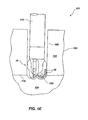
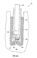
- rotary drill bit 410 of the present invention may be disposed within casing section 404 for drilling through the casing shoe 406, cement 420 therebelow, and into the formation 440.
- rotary drill bit 410 As may be recognized, rotary drill bit 410, as shown in FIG. 3A , must drill through transitions or boundary surfaces between the casing shoe 406, cement 420, and formation 440 prior to drilling a full size borehole within formation 440.
- rotary drill bit 410 disposed at the end of drill string 408 encounters and drills the inner profile 409 of casing shoe 406, which may typically comprise aluminum or other relatively malleable metal or alloy.
- rotary drill bit 410 encounters the upper boundary surface of cement 420, which may substantially conform to the outer profile 407 of casing shoe 406.
- Cement 420 may comprise a hardened material, for instance concrete, including a binding substance such as cement and an aggregate, such as sand or gravel, as known in the art.
- rotary drill bit 410 may engage formation 440 along boundary surface 403, the topography of which may be determined by the drilling tool (not shown) which was used to form borehole 402. It may also be apparent that the geometry of the above-described transitions or boundary surfaces may be known or to some extent, predictable, by selection of the drilling tool (not shown) employed to form borehole 402, the casing shoe 406, or both. Further, casing shoe 406, cement 420, and formation 440 may be characterized as different regions that exhibit one or more distinct drilling characteristics. Since the constituents and mechanical properties of each of casing shoe 406, cement 420, and formation 440 may be different or distinct, drilling within each may exhibit unique forces or behavior.
- rotary drill bit 410 may include redundant cutting elements 412B.
- FIG. 3B shows a partial schematic side cross-sectional view of rotary drill bit 410 as if each of cutting elements 412 were rotated into a single blade 414 extending from bit body 413, in relation to longitudinal axis 411 and along profile 430. Redundant cutting elements 412B may be positioned at the longitudinally lowermost cutting element position of any of cutting elements 412, as shown in FIG. 3B . Accordingly, redundant cutting elements 412B may engage the inner profile 409 of casing shoe 406, the upper surface of cement 420 defined by the outer profile 407 of casing shoe 406, and the boundary surface 403 of formation 440, all as shown in FIG. 3A , prior to any other cutting elements 412 engaging same Such a configuration may inhibit damage that may occur if only one cutting element 412 were positioned at the longitudinally lowermost cutting element position upon rotary drill bit 410.
- the cutting element position of initial engagement of the rotary drill bit 410 in relation to each of the transitions between casing shoe 406, cement 420, and formation 440 may be positioned differently. Put another way, different cutting element positions may initially contact the transitions between casing shoe 406 and cement 420, and between the cement 420 and the formation 440, depending on the shape thereof, respectively in relation to the profile 430 shape. Therefore, the present invention contemplates that rotary drill bit 410 may include more than one group or set of redundant cutting elements at different radial positions thereon.
- FIG. 3C shows a partial schematic side cross-sectional view of rotary drill bit 410 as if each of cutting elements 412 were rotated into a single blade 414 along profile 430.
- FIG. 3C also shows casing shoe 406 having inner profile 409 in relation to longitudinal axis 411.
- the redundant cutting elements 412B1 may be beneficial with respect to drilling into the inner profile 409 of casing shoe 406, since the cutting element position of redundant cutting elements 412B1 may initially contact, prior to other cutting elements 412, the inner profile 409 of casing shoe 406 upon drilling thereinto.
- outer profile 407 of casing shoe 406 may be shaped substantially congruently with respect to inner profile 409, which may cause the upper surface of cement 420 to be initially contacted by redundant cutting elements 412B 1.
- outer profile 407 may be shaped differently than inner profile 409. In such a configuration, additional redundant cutting elements (not shown) may be provided upon rotary drill bit 410 to initially contact the boundary surface between outer profile 409 and cement 420.
- FIG. 3D shows a partial schematic side cross-sectional view of rotary drill bit 410 as if each of cutting elements 412 were rotated into a single blade 414 along profile 430, in relation to longitudinal axis 411.
- FIG. 3D further shows boundary surface 403 of formation 440 in relation two longitudinal axis 411.
- redundant cutting elements 412B1 may not initially contact boundary surface 403 of formation 440, it may be appreciated that the redundant cutting elements 412B2 may be beneficial with respect to drilling into the boundary surface 403 of formation 440, since the cutting element position of redundant cutting elements 412B2 may initially contact, prior to other cutting elements 412 or 412B1, the boundary surface 403 of formation 440 upon drilling thereinto.
- rotary drill bit 410 may include both redundant cutting elements 412B 1 and 412B2 to avoid damage during drilling of casing shoe 406, cement 420, and formation 403.
- FIG. 3E shows a partial schematic side cross-sectional view of rotary drill bit 410 as if each of cutting elements 412 were rotated into a single blade 414 along profile 430 in relation to longitudinal axis 411, including both redundant cutting elements 412B1 and 412B2.
- Such a cutting element configuration upon rotary drill bit 410 may be advantageous in sequentially drilling into the casing shoe 406 and formation 440 as respectively shown in FIGS. 3C and 3D .
- a continuous region of profile 430 may include two or more radially adjacent redundant cutting elements.
- FIG. 3F which shows a partial schematic side cross-sectional view of the rotary drill bit of the present invention
- redundant cutting elements 412B1, 412B2, 412B3, 412B4, and 412B5 may be placed radially adjacent one another, respectively, upon profile 430.
- Such a configuration may effectively protect region R1 from damage when drilling between regions of a material having differing properties.
- Such a configuration may be desirable for protecting against excessive damage in response to a variety of boundary surface orientations or locations which may be encountered between differing regions of a material being drilled.
- a rotary drill bit of the present invention may include one or more regions, each of which includes two or more redundant cutting elements, without limitation.
- any of the redundant cutting elements disposed on a rotary drill bit contemplated by the present invention may be configured to exhibit enhanced durability in relation to other cutting elements disposed thereon.
- redundant cutting elements may be disposed at relatively higher backrake angles than other cutting elements disposed on a rotary drill bit.
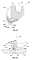
- FIG. 3G depicts a schematic side cross-sectional view of a redundant cutting element 412B ( FIG. 3B ) disposed within rotary drill bit 410 during drilling of a subterranean formation 440.
- the cutting element 412B may include a superabrasive table 442 sintered onto a substrate 444.
- the superabrasive table 442 may include a chamfer or rake land 446, as described in more detail hereinbelow.
- the cutting element 412B may include a cutting face 460, which cuts the formation 440, contacting it along cutting face 460, rake land 446, and at lower cutting edge 452.
- cutting element 412B cuts into subterranean formation 440, generating particles or at least partially continuous chips 454 sliding across the cutting face 460.
- cutting element 412B is disposed at a backrake angle ⁇ , in relation to vertical reference line 461.
- Such a configuration is termed "negative backrake,” as known in the art.
- the magnitude of negative backrake angle ⁇ of redundant cutting elements 412B may be greater than the magnitude of negative backrake angle of other cutting elements 412 of rotary drill bit 410.
- Such a configuration may provide greater durability to redundant cutting elements 412B in relation to cutting elements 412 of rotary drill bit 410.
- redundant cutting elements may be different from other cutting elements disposed on the rotary drill bit.
- redundant cutting elements may be configured with chamfers, rake lands, or both that improve the durability thereof.
- One particular configuration for redundant cutting elements may be as disclosed in U.S. Patent No. 5,881,830 to Cooley , assigned to the assignee of the present invention.
- Another particular, embodiment that redundant cutting element 412B may comprise is disclosed in U.S. Patent No. 5,706,906 to Jurewicz et. al., assigned to the assignee of the present invention.
- a redundant cutting element 412B may include a superabrasive table 442 of about 0.178 to 0.3 81 centimeter in thickness, measured along the longitudinal axis of the cutting element 412B between a leading portion of the cutting face 460 and the superabrasive table 442/substrate 444 interface.
- the periphery of the superabrasive table 442 may include a rake land 446 disposed at a rake land angle ⁇ for engaging and drilling a subterranean formation.
- the rake land angle may be in the range of 30° to 60° and the length of the rake land may be at least about 0.127 centimeter, measured from the inner radial extent of the rake land 446 (or the center of the cutting face 460, if the rake land 446 extends thereto) to the side surface 466 of the cutting element 412B along or parallel to (e.g., at the same angle) to the actual surface of the rake land 446.
- the initial engagement between a cutting element of a rotary drill bit and a change in subterranean formation or other material properties may be positioned depending on the orientation and shape of the boundary surface between regions of the subterranean formation, different subterranean formations, or other materials in the path of the rotary drill bit and the orientation of the rotary drill bit as it engages or encounters the boundary.
- FIG. 4A-1 shows a partial schematic side cross-sectional view of rotary drill bit 310 as if each of cutting elements 3-12 were rotated into a single blade 314 extending from bit body 313 along profile 330 in relation to longitudinal axis 311.
- Formation region 360 is also shown as having a boundary surface 361 that is substantially planar, and is oriented at an angle with respect to longitudinal axis 311.
- redundant cutting elements 312 may beneficially contact formation region 360, since the cutting element position of redundant cutting elements 312B1 initially contact, prior to other cutting elements 312 of rotary drill bit 310, the boundary surface 361 thereof, upon drilling thereinto.
- redundant cutting elements that sequentially contact a boundary surface between regions having different properties may reduce the total damage that may occur to a single cutting element at a given cutting element position, because such amount of damage may be distributed among more than one cutting element.
- more than one contact between redundant cutting elements and a formation region which is harder than the region thereabove may tend to slow progress thereinto, which may reduce the magnitude of the depth of cut that accumulates between periods of non-contact with the harder formation and correspondingly reduce or distribute damage to the redundant cutting elements.
- the circumferential position of the cutting elements may be considered, and other cutting element positions may be made redundant so as to prevent overloading to any one cutting element (redundant or non-redundant) of the rotary drill bit 310.
- a rotary drill bit may include redundant cutting elements in more than one position, in relation to expected positions of initial engagement of formation changes, wherein at least one expected position of initial contact with formation changes may occur substantially concurrently, while at least another expected position of initial contact may occur substantially sequentially.
- a rotary drill bit may be structured for encountering a formation change.
- a profile region may be structured so that cutting elements positioned thereon substantially concurrently contact a boundary surface between adjacent subterranean formations.
- at least a portion of a profile of rotary drill bit may be structured for causing initial contact between a plurality of cutting elements positioned thereon and an anticipated boundary surface of a subterranean formation.
- at least a portion of a profile of rotary drill bit may be structured for causing substantially concurrent contact between the plurality of cutting elements positioned thereon and an anticipated boundary surface of a subterranean formation
- FIG. 4A-2 shows a rotary drill bit 310B having a profile 330B including a region 331B thereof structured for contacting boundary surface 361 of formation region 360.
- rotary drill bit 310B may drill into subterranean formation such that region 331B, including a plurality of cutting elements 312, initially contacts boundary surface 361.
- the plurality of cutting elements 312 within region 331B may, substantially concurrently contact boundary surface 361.
- Such a configuration may distribute the forces associated with initial contact of boundary surface 361 between the plurality of cutting element 312 within region 331B.
- at least some of the plurality of cutting element 312 within region 331B may be positioned upon different blades of rotary drill bit 310.
- some of the plurality of cutting elements 312 within region 331B may be positioned upon one blade of rotary drill bit 310. Further, some of the plurality of cutting elements 312 within region 331B may be redundant; or, alternatively, none of the plurality of cutting elements within region 331 B may be redundant.
- FIG. 4A-3 shows a rotary drill bit 310C having a profile 330C including a region 331C thereof structured for contacting boundary surface 361 of formation region 360.
- rotary drill bit 310C may drill into subterranean formation such the plurality of cutting elements 312 within region 331C initially contact boundary surface 361.
- the plurality of cutting elements within region 331C may be structured and positioned in relation to boundary surface 361 of subterranean formation 360 in a manner as discussed above with respect to FIG. 4A-2 .
- the plurality of cutting, elements 312 within region 331C may, substantially concurrently contact boundary surface 361.
- Such a configuration may distribute the forces associated with initial contact of boundary surface 361 between the plurality of cutting element 312 within region 331C. It may be appreciated that although both regions 331B and 331C ( FIGS. 4A-2 and 4A-3 ) are depicted as corresponding to a substantially planar-shaped (in cross-section) boundary surface 361 of a portion of subterranean formation 360, the present invention is not so limited.
- a region of a rotary drill bit may be structured for carrying a plurality of cutting elements for substantially concurrently contacting an arcuately shaped (in cross-section) (e.g., circular, oval, ellipsoid, hemispherical, rounded, etc.) boundary surface 361 of a portion of a subterranean formation.
- an arcuately shaped (in cross-section) e.g., circular, oval, ellipsoid, hemispherical, rounded, etc.
- positions of cutting elements 312 for initial engagement with a boundary surface may vary due to manufacturing limitations or for other reasons.
- the actual position of cutting elements 312 e.g., within region 331B and 331C
- cutting elements 312 may be placed substantially at a position for initial engagement with a formation according to the present invention.
- FIG. 4B shows a schematic side view of rotary drill bit 310 drilling borehole 370 within formation 372.
- Formation 372 comprises region 374, region 360, and region 376, wherein region 374 and region 360 are adjacent to one another along boundary surface 361, while region 360 and region 376 are adjacent one another along boundary surface 375.
- Rotary drill bit 310 may be configured to engage each of boundary surfaces 361 and 375 with differently radially positioned redundant cutting elements. To this end, FIG.
- FIG. 4C shows a partial schematic side cross-sectional view of rotary drill bit 310 as if each of cutting elements 312 were rotated into a single blade 314 along profile 330 in relation to longitudinal axis 311.
- Redundant cutting elements 312B1 may be beneficial with respect to drilling into the boundary surface 361 between region 374 and region 360
- redundant cutting elements 312B2 may be beneficial with respect to drilling into the boundary surface 375 between region 360 and region 376.
- at least a portion of the profile (not shown) of rotary drill bit 310 may be configured as discussed above (e.g., in relation to FIGS. 4A-2 and 4A-3 ), wherein a profile thereof includes a region having a plurality of cutting elements structured for contacting boundary surface 361 of formation region 360 substantially concurrently.
- boundary surface 361 may not be symmetric about longitudinal axis 311, so initial contact therewith by redundant cutting elements 312B1 (or a region having a plurality of cutting elements as discussed in relation to FIGS. 4A-2 and 4A-3 ) may be substantially sequential, while initial contact with boundary surface 375, which may be substantially symmetric about longitudinal axis 311, by redundant cutting elements 312B2 may be substantially concurrent.
- redundant cutting elements 312B2 may be substantially concurrent.
- many alternatives are possible, limited only by a drilling profile geometry of a rotary drill bit and a direction of drilling therewith, in relation to a boundary surface geometry intersecting therewith.
- rotary drill bit 310 may be designed specifically to include redundant cutting elements 312B1 and 312B2 at the positions of initial engagement therewith, depending on the orientation thereof as well as the anticipated direction of drilling thereinto.
- rotary drill bit may be designed specifically to include cutting elements 312 within a selected profile region (As shown in FIGS. 4A-2 and 4A-3 ) at a position of initial engagement with a boundary surface, depending on the orientation thereof as well as the anticipated direction of drilling thereinto.
- boundary surfaces 361 and 375 between different regions 374, 360, and 376 of formation 372 may be determined, as by logging, seismic measurements, or as otherwise known in the art. Also, an anticipated drilling path (not shown) may be selected for drilling into and through boundary surfaces 361 and 375 between different regions 374, 360, and 376 of formation 372.
- Analyzing the anticipated drilling path (not shown) with respect to boundary surfaces 361 and 375 between different regions 374, 360, and 376 of formation 372 and further in relation to a selected cutting element profile 330, may indicate at least one cutting element position that contacts at least one of the boundary surfaces 361 and 373 prior to other cutting elements 312. Accordingly, redundant cutting elements 312B 1 or 312B2, or other redundant cutting elements, may be placed, by design, at the indicated cutting element positions according to predicted or assumed boundary surfaces in a selected structure to be drilled. Alternatively, a plurality of cutting elements positioned upon at least a portion of the profile (not shown) of rotary drill bit 310 may be configured as discussed above (e.g., in relation to FIGS.
- cutting element profiles and individual cutting element positions may be modified during the design process, as desired.
- An analogous design process may also apply to design of a rotary drill bit for drilling through a casing shoe, associated cement, and into a subterranean formation, as described above, without limitation.
- a rotary drill bit of the present invention may be directionally drilled into a formation with different regions which are oriented differently so as to contact the formation changes or boundary surfaces with redundant cutting elements. It may be desirable to minimize or at least limit the redundant cutting elements included by a rotary drill bit.
- One reason for limiting redundancy of cutting elements upon a rotary drill bit may be simply a consideration of space in relation to the number of blades, spacing thereof, and the size of the rotary drill bit. Additional reasons for limiting redundant cutting elements may be that redundant cutting elements may decrease drilling efficiency or decrease drilling aggressiveness.
- the present invention contemplates a method of drilling a subterranean formation that includes modifying a drilling direction to engage a boundary between regions of the formation so as to initially engage or contact a boundary with redundant cutting elements. Such a method of drilling may reduce the redundant cutting elements that are needed to effectively drill into a formation with different regions.
- FIGS. 5A-5C show a rotary drill bit 510 of the present invention drilling into formation 500 and forming borehole 512 therein as it progresses through regions 502, 504, and 506. Regions 502 and 504 are adjacent one another along boundary surface 503, while regions 504 and 506 are adjacent one another along boundary surface 505.
- Rotary drill bit 510 may include cutting elements 212 and redundant cutting elements 212B positioned and configured as described in relation to rotary drill bit 210 as shown in FIGS. 2B and 2C , so that redundant cutting elements 212B may initially engage boundary surfaces 503 and 505 if the longitudinal axis 511 (drilling axis) of rotary drill bit 510 is oriented substantially perpendicular thereto as it contacts therewith.
- a plurality of cutting elements 212 positioned upon at least a portion of the profile (not shown) of rotary drill bit 510 may be configured as discussed above (e.g., in relation to FIGS. 4A-2 and 4A-3 ) for contacting boundary surface 361 of formation region 360 substantially concurrently.
- the orientation of longitudinal axis 511 of rotary drill bit 510 may be altered or changed during drilling of borehole 512 so that redundant cutting elements 212B disposed thereon initially engage boundary surface 503.
- the orientation of the drilling direction or longitudinal axis 511 of rotary drill bit 510 may be altered or changed during drilling of borehole 512 so that redundant cutting elements 212B disposed thereon initially engage boundary surface 505.
- Changing the orientation or drilling direction of rotary drill bit 510 may be accomplished by directional drilling methods and apparatus as known in the art. Such a method of drilling may advantageously protect the cutting elements 212 disposed on the rotary drill bit 510 during drilling through boundary surfaces between regions 502, 504, and 506 of formation 500 while also facilitating enhanced drilling performance within regions 502, 504, and 506 of formation 500.
- boundary surfaces 503 and 505 in order to selectively orient the direction of drilling, the orientation, position, or both of the boundary surfaces 503 and 505 must be at least partially determined. There may be several ways to at least partially determine the orientation, position, or both of boundary surfaces 503 and 505. For instance, boundary surfaces 503 and 505 may be at least partially determined by logging another hole that is drilled though the formation regions, by seismic measurements, by measurement while drilling systems, as known in the art, or by a combination of the foregoing techniques. The determinations of such systems may be considered during the operation of drilling with drill bit 510 and the direction of drilling (orientation of longitudinal axis 511) may be modified accordingly.
- redundant cutting elements according to the present invention may be configured so as to maintain or preserve a stability characteristic of the rotary drill bit during the initial drilling engagement of a region.
- the first two stability approaches involve configuring the rotary drill bit with a selected lateral imbalance force configuration.
- a so-called anti-whirl design or high-imbalance concept typically endeavors to generate a directed net lateral force (i.e., the net lateral force being the summation of each of the lateral drilling forces generated by each of the cutting elements disposed on a rotary drill bit) toward a gage pad or bearing pad that slidingly engages the wall of the borehole.
- a directed net lateral force i.e., the net lateral force being the summation of each of the lateral drilling forces generated by each of the cutting elements disposed on a rotary drill bit
- Such a configuration may tend to stabilize a rotary drill bit as it progresses through a subterranean formation.
- a so-called low-imbalance design concept endeavors to significantly reduce, if not eliminate, the net lateral force generated by the cutting elements so that the lateral forces generated by each of the cutting elements substantially cancel one another.
- grooves may be formed into the formation, by selective, radially spaced placement of cutting elements upon the rotary drill bit. Accordingly, the grooves or kerfs may tend to mechanically inhibit the rotary drill bit from vibrating or oscillating during drilling. Of course, grooves or kerfs may not effectively stabilize the rotary drill bit if the magnitude of the net lateral force becomes large enough, or if torque fluctuations become large enough. It should also be noted that the aforementioned stability approaches are typically developed and analyzed in reference to drilling of a homogeneous material or homogeneous subterranean formation.
- the present invention that transition into a region of different drilling characteristics may adversely affect the stability approach so employed. More specifically, as the redundant cutting elements or cutting elements within a selected region of a rotary drill bit of the present invention initially engage a region with different drilling characteristics than the rest of the cutting elements thereon, the net lateral force as well as the torque may be altered, which may deleteriously influence the stability characteristics of the rotary drill bit, which may be typically designed according to the assumption of homogeneity of the material to be drilled.
- the present invention contemplates that the net lateral force of a group of redundant cutting elements may be minimized or oriented within a given range of directions.
- the redundant cutting elements or cutting elements within a selected region of a profile may be sized and configured to generate individual lateral forces that at least partially cancel with one another.
- the vector addition of each lateral force of the at least two redundant cutting elements or cutting elements within a selected region of a profile may be smaller than the arithmetic summation of the magnitude of each of the lateral forces.
- redundant cutting elements or cutting elements within a selected region of a profile may be sized and configured to generate individual lateral forces that are relatively small in relation to the net lateral force produced by the other cutting elements disposed upon a rotary drill bit.
- redundant cutting elements or cutting elements within a region of a profile may be positioned and configured so as to generate a net lateral imbalance force in a given direction or within a selected range of directions.
- the geometry, back rake angle, side rake angle, exposure, size, and position of a cutting element disposed on a rotary drill bit may influence the forces and torques that are generated by drilling therewith.
- predictive models and simulations may be employed to estimate or predict such forces and torque values or magnitudes in relation to a selected rotary drill bit design and material to be drilled.
- redundant cutting elements 522, 524, and 526 may be sized, positioned, and configured to minimize or reduce the net lateral force, the net torque, or combinations thereof that may be produced by drilling therewith. Particularly, by initial engagement with a region of a drilling structure, such as different regions of a subterranean formation or different regions of casing assemblies.
- the forces that are produced by associated redundant cutting elements 522, 524, and 526 are labeled as lateral (or radial) forces 522L, 524L, and 526L, respectively, while tangential forces are labeled 522T, 524T, and 526T, respectively.
- lateral forces or radial forces
- tangential forces are labeled 522T, 524T, and 526T, respectively.
- both the tangential and radial forces influence an overall lateral imbalance force, as is known in the art.
- redundant cutting elements 522, 524, and 526 may be sized and configured so that lateral forces 522L, 524L, 526 L, 522T, 524T, and 526T substantially cancel (via vector addition) in combination with one another.
- the net lateral force, by vector addition of forces of each of redundant cutting elements 522, 524, and 526 may have a relatively small magnitude or may have substantially no magnitude.
- redundant cutting elements 522, 524, and 526 may be sized and configured to generate individual forces that at least partially cancel with one another or have a magnitude that is relatively small in relation to the magnitude of net lateral force produced by the other cutting elements disposed upon a rotary drill bit.
- the magnitude of the overall lateral imbalance of the rotary drill bit (when drilling a homogeneous formation region) may be changed by less than about 20% during initial engagement by redundant cutting elements 522, 524, and 526 of a different region of a structure in relation to the magnitude of lateral imbalance exhibited when drilling a homogeneous region.
- the magnitude of the imbalance force of the redundant cutting elements 522, 524, and 524 may not be limited. However, as discussed hereinbelow, if the net imbalance force of redundant cutting elements 522, 524, and 526 is oriented in a desired direction, it may be preferable to maintain a selected imbalance force direction exhibited by the drill bit for maintaining stability thereof.
- the overall direction of the imbalance force of redundant cutting elements 522, 524, and 526 may be within ⁇ 70° with respect to a net imbalance direction exhibited by the bit when drilling a homogeneous region.
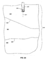
- Such a configuration may be advantageous for maintaining a desired direction of an imbalance force exhibited by a drill bit during drilling into a subterranean formation having differing regions. For example, as shown in FIG. 6A , a net lateral imbalance force L1 may be generated when the drill bit drills a homogeneous formation.
- a net imbalance force L2 (of redundant cutting elements 522, 524, and 526) may be generated when redundant cutting elements 522, 524, and 526 engage a boundary surface between two different regions of a subterranean formation, and L2 may have a direction within ⁇ 70° of the direction of L1, as illustrated by reference lines 601 and 603.
- cutting elements 522, 524, and 526 may not be redundant and may be positioned upon at least a portion of the profile (not shown) of rotary drill bit 510 configured as discussed above (e.g., in relation to FIG. 4A-2 and 4A-3 ).
- cutting elements 522, 524, and 526 may be positioned at different radial positions R, R1, R2 as shown in FIG. 6B .
- cutting elements 522, 524, and 526 may be sized and configured so that lateral forces 522L, 524L, 526L, 522T, 524T, and 526T substantially cancel (via vector addition) in combination with one another.
- the net lateral force, by vector addition of lateral forces 522L, 524L, 526L, 522T, 524T, and 526T may have a relatively small magnitude or may have substantially no magnitude.
- cutting elements 522, 524, and 526 may be sized and configured to generate individual lateral forces that at least partially cancel with one another or have a magnitude that is relatively small in relation to the magnitude of net lateral force produced by the other cutting elements disposed upon a rotary drill bit.
- the magnitude of the overall lateral imbalance of the rotary drill bit may be changed by less than about 20% during initial engagement by cutting elements 522, 524, and 526 of a different region of a structure in relation to the magnitude of lateral imbalance exhibited when drilling a homogeneous region.
- the net imbalance force of redundant cutting elements 522, 524, and 526 is oriented in a desired direction, it may be preferable to maintain a selected imbalance of the drill bit for maintaining stability thereof.
- the overall direction of the imbalance force of cutting elements 522, 524, and 526 may be within ⁇ 70° with respect to a net imbalance direction exhibited by the bit when drilling a homogeneous region.
- Such a configuration may be advantageous for maintaining a desired direction of imbalance of a drill bit during drilling into different subterranean formations.
- a net lateral imbalance force L1 may be generated when the drill bit drills into a homogeneous formation.
- a net imbalance force L2 (of cutting elements 522, 524, and 526) may be generated when cutting elements 522, 524, and 526 engage a boundary surface between two different regions of a subterranean formation, and L2 may have a direction within ⁇ 70° of the direction of L1, as illustrated by reference lines 601 and 603.
Landscapes
- Engineering & Computer Science (AREA)
- Life Sciences & Earth Sciences (AREA)
- Geology (AREA)
- Mining & Mineral Resources (AREA)
- Mechanical Engineering (AREA)
- Physics & Mathematics (AREA)
- Environmental & Geological Engineering (AREA)
- Fluid Mechanics (AREA)
- General Life Sciences & Earth Sciences (AREA)
- Geochemistry & Mineralogy (AREA)
- Earth Drilling (AREA)
Applications Claiming Priority (2)
| Application Number | Priority Date | Filing Date | Title |
|---|---|---|---|
| US11/064,108 US7455125B2 (en) | 2005-02-22 | 2005-02-22 | Drilling tool equipped with improved cutting element layout to reduce cutter damage through formation changes, methods of design and operation thereof |
| EP06735743A EP1851410A1 (de) | 2005-02-22 | 2006-02-22 | Mit einer verbesserten schneideelementanordnung ausgestattetes bohrwerkzeug zur reduktion von schneideschäden durch formationsänderungen, verfahren zu dessen entwurf und bohrvorgang damit |
Related Parent Applications (2)
| Application Number | Title | Priority Date | Filing Date |
|---|---|---|---|
| EP06735743A Division EP1851410A1 (de) | 2005-02-22 | 2006-02-22 | Mit einer verbesserten schneideelementanordnung ausgestattetes bohrwerkzeug zur reduktion von schneideschäden durch formationsänderungen, verfahren zu dessen entwurf und bohrvorgang damit |
| EP06735743.4 Division | 2006-02-22 |
Publications (2)
| Publication Number | Publication Date |
|---|---|
| EP2039876A2 true EP2039876A2 (de) | 2009-03-25 |
| EP2039876A3 EP2039876A3 (de) | 2010-06-02 |
Family
ID=36384487
Family Applications (2)
| Application Number | Title | Priority Date | Filing Date |
|---|---|---|---|
| EP06735743A Withdrawn EP1851410A1 (de) | 2005-02-22 | 2006-02-22 | Mit einer verbesserten schneideelementanordnung ausgestattetes bohrwerkzeug zur reduktion von schneideschäden durch formationsänderungen, verfahren zu dessen entwurf und bohrvorgang damit |
| EP08022550A Withdrawn EP2039876A3 (de) | 2005-02-22 | 2006-02-22 | Mit einer verbesserten Schneidelementanordnung ausgestattetes Bohrwerkzeug zur Reduktion von Schneidelementschäden durch Formationsänderungen, Verfahren zu dessen Entwurf und Bohrvorgang |
Family Applications Before (1)
| Application Number | Title | Priority Date | Filing Date |
|---|---|---|---|
| EP06735743A Withdrawn EP1851410A1 (de) | 2005-02-22 | 2006-02-22 | Mit einer verbesserten schneideelementanordnung ausgestattetes bohrwerkzeug zur reduktion von schneideschäden durch formationsänderungen, verfahren zu dessen entwurf und bohrvorgang damit |
Country Status (7)
| Country | Link |
|---|---|
| US (2) | US7455125B2 (de) |
| EP (2) | EP1851410A1 (de) |
| CN (1) | CN101160445A (de) |
| CA (1) | CA2598428C (de) |
| MX (1) | MX2007010187A (de) |
| RU (1) | RU2007134971A (de) |
| WO (1) | WO2006091641A1 (de) |
Cited By (1)
| Publication number | Priority date | Publication date | Assignee | Title |
|---|---|---|---|---|
| US8127869B2 (en) | 2009-09-28 | 2012-03-06 | Baker Hughes Incorporated | Earth-boring tools, methods of making earth-boring tools and methods of drilling with earth-boring tools |
Families Citing this family (30)
| Publication number | Priority date | Publication date | Assignee | Title |
|---|---|---|---|---|
| US7860693B2 (en) * | 2005-08-08 | 2010-12-28 | Halliburton Energy Services, Inc. | Methods and systems for designing and/or selecting drilling equipment using predictions of rotary drill bit walk |
| CA2625012C (en) | 2005-08-08 | 2016-05-03 | Halliburton Energy Services, Inc. | Methods and systems for design and/or selection of drilling equipment based on wellbore drilling simulations |
| RU2008122703A (ru) * | 2005-11-08 | 2009-12-20 | Бейкер Хьюз Инкорпорейтед (Us) | Долото лопастного типа для роторного бурения и способы оптимизации их эффективности и износостойкости |
| US20080053251A1 (en) * | 2006-08-31 | 2008-03-06 | Wingerter Eugene J | Solid Waste Screening System |
| US7621348B2 (en) | 2006-10-02 | 2009-11-24 | Smith International, Inc. | Drag bits with dropping tendencies and methods for making the same |
| RU2009133697A (ru) * | 2007-02-12 | 2011-03-20 | Бейкер Хьюз Инкорпорейтед (Us) | Лопастное долото для вращательного бурения |
| US7703557B2 (en) * | 2007-06-11 | 2010-04-27 | Smith International, Inc. | Fixed cutter bit with backup cutter elements on primary blades |
| CN101868293B (zh) * | 2007-10-03 | 2013-07-03 | Emd密理博公司 | 堆叠板式过滤盒体 |
| US9016407B2 (en) | 2007-12-07 | 2015-04-28 | Smith International, Inc. | Drill bit cutting structure and methods to maximize depth-of-cut for weight on bit applied |
| US8127863B2 (en) | 2007-12-10 | 2012-03-06 | Smith International, Inc. | Drill bit having enhanced stabilization features and method of use thereof |
| EP2240881A4 (de) | 2007-12-14 | 2015-09-30 | Halliburton Energy Services Inc | Verfahren und systeme zur vorhersage eines drehbohrgangs sowie zum entwurf von drehbohrern und anderen bohrwerkzeugen |
| US8100202B2 (en) | 2008-04-01 | 2012-01-24 | Smith International, Inc. | Fixed cutter bit with backup cutter elements on secondary blades |
| GB2498133B (en) | 2008-12-11 | 2013-11-13 | Halliburton Energy Serv Inc | Multilevel force balanced downhole drilling tools and methods |
| CN102414393B (zh) * | 2009-06-05 | 2014-09-10 | 维拉国际工业有限公司 | 套管钻头和套管铰孔器设计 |
| US8887839B2 (en) * | 2009-06-25 | 2014-11-18 | Baker Hughes Incorporated | Drill bit for use in drilling subterranean formations |
| US8720611B2 (en) | 2010-12-15 | 2014-05-13 | Halliburton Energy Services, Inc. | PDC bits with cutters laid out in both spiral directions of bit rotation |
| US9115552B2 (en) | 2010-12-15 | 2015-08-25 | Halliburton Energy Services, Inc. | PDC bits with mixed cutter blades |
| US10030452B2 (en) | 2013-03-14 | 2018-07-24 | Smith International, Inc. | Cutting structures for fixed cutter drill bit and other downhole cutting tools |
| US10309156B2 (en) | 2013-03-14 | 2019-06-04 | Smith International, Inc. | Cutting structures for fixed cutter drill bit and other downhole cutting tools |
| DE112014004312T5 (de) | 2013-09-20 | 2016-06-23 | Halliburton Energy Services, Inc. | Zusammensetzungen aus Elastomer und thermisch leitfähigen Kohlefasern für Dichtungen von Rollenbohrmeißeln |
| WO2015099717A1 (en) | 2013-12-26 | 2015-07-02 | Halliburton Energy Services, Inc. | Multilevel force balanced downhole drilling tools including cutting elements in a track-set configuration |
| GB2537260B (en) | 2013-12-26 | 2018-04-04 | Halliburton Energy Services Inc | Multilevel force balanced downhole drilling tools including cutting elements in a step profile configuration |
| US10287825B2 (en) | 2014-03-11 | 2019-05-14 | Smith International, Inc. | Cutting elements having non-planar surfaces and downhole cutting tools using such cutting elements |
| US10246945B2 (en) | 2014-07-30 | 2019-04-02 | Baker Hughes Incorporated, A GE Company, LLC | Earth-boring tools, methods of forming earth-boring tools, and methods of forming a borehole in a subterranean formation |
| US10107040B2 (en) | 2015-09-23 | 2018-10-23 | Baker Hughes, A Ge Company, Llc | Earth-boring tool having back up cutting elements with flat surfaces formed therein and related methods |
| CN106761424B (zh) * | 2017-01-21 | 2019-04-12 | 四川川石·克锐达金刚石钻头有限公司 | 一种切削元件成对设置的pdc钻头 |
| CN111604720B (zh) * | 2020-06-03 | 2021-07-06 | 哈尔滨工业大学 | 一种金刚石微径铣刀不平衡量修正方法 |
| CN112127799A (zh) * | 2020-10-14 | 2020-12-25 | 深圳市海明润超硬材料股份有限公司 | 一种金刚石复合片钻头 |
| CN114592796B (zh) * | 2022-05-10 | 2022-07-12 | 胜利油田万和石油工程技术有限责任公司 | 一种适用于致密泥岩地层的pdc钻头 |
| US12595704B2 (en) | 2023-05-26 | 2026-04-07 | Baker Hughes Oilfield Operations Llc | Casing drill bit facilitating drill-out thereof, and related methods of manufacture and use |
Citations (13)
| Publication number | Priority date | Publication date | Assignee | Title |
|---|---|---|---|---|
| US4429755A (en) | 1981-02-25 | 1984-02-07 | Williamson Kirk E | Drill with polycrystalline diamond drill blanks for soft, medium-hard and hard formations |
| US4932484A (en) | 1989-04-10 | 1990-06-12 | Amoco Corporation | Whirl resistant bit |
| US5010789A (en) | 1989-02-21 | 1991-04-30 | Amoco Corporation | Method of making imbalanced compensated drill bit |
| US5042596A (en) | 1989-02-21 | 1991-08-27 | Amoco Corporation | Imbalance compensated drill bit |
| US5314033A (en) | 1992-02-18 | 1994-05-24 | Baker Hughes Incorporated | Drill bit having combined positive and negative or neutral rake cutters |
| US5549171A (en) | 1994-08-10 | 1996-08-27 | Smith International, Inc. | Drill bit with performance-improving cutting structure |
| US5605198A (en) | 1993-12-09 | 1997-02-25 | Baker Hughes Incorporated | Stress related placement of engineered superabrasive cutting elements on rotary drag bits |
| US5607024A (en) | 1995-03-07 | 1997-03-04 | Smith International, Inc. | Stability enhanced drill bit and cutting structure having zones of varying wear resistance |
| US5706906A (en) | 1996-02-15 | 1998-01-13 | Baker Hughes Incorporated | Superabrasive cutting element with enhanced durability and increased wear life, and apparatus so equipped |
| US5873422A (en) | 1992-05-15 | 1999-02-23 | Baker Hughes Incorporated | Anti-whirl drill bit |
| US5881830A (en) | 1997-02-14 | 1999-03-16 | Baker Hughes Incorporated | Superabrasive drill bit cutting element with buttress-supported planar chamfer |
| US6164394A (en) | 1996-09-25 | 2000-12-26 | Smith International, Inc. | Drill bit with rows of cutters mounted to present a serrated cutting edge |
| US20020157869A1 (en) | 2001-03-26 | 2002-10-31 | Halliburton Energy Services, Inc. | Rock drill bits, methods, and systems with transition-optimized torque distribution |
Family Cites Families (33)
| Publication number | Priority date | Publication date | Assignee | Title |
|---|---|---|---|---|
| US4106578A (en) * | 1976-05-04 | 1978-08-15 | Leaman Rex Beyer | Percussion drill bit |
| US4266621A (en) * | 1977-06-22 | 1981-05-12 | Christensen, Inc. | Well casing window mill |
| US4323130A (en) * | 1980-06-11 | 1982-04-06 | Strata Bit Corporation | Drill bit |
| USRE32036E (en) * | 1980-06-11 | 1985-11-26 | Strata Bit Corporation | Drill bit |
| US4872520A (en) * | 1987-01-16 | 1989-10-10 | Triton Engineering Services Company | Flat bottom drilling bit with polycrystalline cutters |
| US4848489A (en) * | 1987-03-26 | 1989-07-18 | Reed Tool Company | Drag drill bit having improved arrangement of cutting elements |
| US4815342A (en) * | 1987-12-15 | 1989-03-28 | Amoco Corporation | Method for modeling and building drill bits |
| CA1333282C (en) * | 1989-02-21 | 1994-11-29 | J. Ford Brett | Imbalance compensated drill bit |
| WO1990012191A1 (en) | 1989-04-06 | 1990-10-18 | Walton Paul G | Triangular oil well drill bit |
| US5111892A (en) * | 1990-10-03 | 1992-05-12 | Sinor L Allen | Imbalance compensated drill bit with hydrostatic bearing |
| US5178222A (en) * | 1991-07-11 | 1993-01-12 | Baker Hughes Incorporated | Drill bit having enhanced stability |
| US5402856A (en) * | 1993-12-21 | 1995-04-04 | Amoco Corporation | Anti-whirl underreamer |
| GB2317195B (en) * | 1994-08-10 | 1998-07-15 | Smith International | Cutting structure of a drill bit and a fixed cutter drill bit |
| US5551522A (en) * | 1994-10-12 | 1996-09-03 | Smith International, Inc. | Drill bit having stability enhancing cutting structure |
| GB2298665B (en) * | 1995-03-08 | 1998-11-04 | Camco Drilling Group Ltd | Improvements in or relating to cutter assemblies for rotary drill bits |
| US5607025A (en) * | 1995-06-05 | 1997-03-04 | Smith International, Inc. | Drill bit and cutting structure having enhanced placement and sizing of cutters for improved bit stabilization |
| US6021858A (en) * | 1996-06-05 | 2000-02-08 | Smith International, Inc. | Drill bit having trapezium-shaped blades |
| US5979571A (en) * | 1996-09-27 | 1999-11-09 | Baker Hughes Incorporated | Combination milling tool and drill bit |
| US5957223A (en) * | 1997-03-05 | 1999-09-28 | Baker Hughes Incorporated | Bi-center drill bit with enhanced stabilizing features |
| GB9708428D0 (en) * | 1997-04-26 | 1997-06-18 | Camco Int Uk Ltd | Improvements in or relating to rotary drill bits |
| US5957225A (en) * | 1997-07-31 | 1999-09-28 | Bp Amoco Corporation | Drilling assembly and method of drilling for unstable and depleted formations |
| US7000715B2 (en) * | 1997-09-08 | 2006-02-21 | Baker Hughes Incorporated | Rotary drill bits exhibiting cutting element placement for optimizing bit torque and cutter life |
| US6230828B1 (en) * | 1997-09-08 | 2001-05-15 | Baker Hughes Incorporated | Rotary drilling bits for directional drilling exhibiting variable weight-on-bit dependent cutting characteristics |
| US6460631B2 (en) * | 1999-08-26 | 2002-10-08 | Baker Hughes Incorporated | Drill bits with reduced exposure of cutters |
| US6298930B1 (en) * | 1999-08-26 | 2001-10-09 | Baker Hughes Incorporated | Drill bits with controlled cutter loading and depth of cut |
| US6397958B1 (en) * | 1999-09-09 | 2002-06-04 | Baker Hughes Incorporated | Reaming apparatus and method with ability to drill out cement and float equipment in casing |
| US6302223B1 (en) * | 1999-10-06 | 2001-10-16 | Baker Hughes Incorporated | Rotary drag bit with enhanced hydraulic and stabilization characteristics |
| US6308790B1 (en) * | 1999-12-22 | 2001-10-30 | Smith International, Inc. | Drag bits with predictable inclination tendencies and behavior |
| US6688410B1 (en) * | 2000-06-07 | 2004-02-10 | Smith International, Inc. | Hydro-lifter rock bit with PDC inserts |
| US6615934B2 (en) * | 2001-08-15 | 2003-09-09 | Smith International, Inc. | PDC drill bit having cutting structure adapted to improve high speed drilling performance |
| US7178609B2 (en) * | 2003-08-19 | 2007-02-20 | Baker Hughes Incorporated | Window mill and drill bit |
| US7395882B2 (en) * | 2004-02-19 | 2008-07-08 | Baker Hughes Incorporated | Casing and liner drilling bits |
| GB0521693D0 (en) * | 2005-10-25 | 2005-11-30 | Reedhycalog Uk Ltd | Representation of whirl in fixed cutter drill bits |
-
2005
- 2005-02-22 US US11/064,108 patent/US7455125B2/en not_active Expired - Lifetime
-
2006
- 2006-02-22 EP EP06735743A patent/EP1851410A1/de not_active Withdrawn
- 2006-02-22 CA CA2598428A patent/CA2598428C/en not_active Expired - Fee Related
- 2006-02-22 EP EP08022550A patent/EP2039876A3/de not_active Withdrawn
- 2006-02-22 CN CNA200680012478XA patent/CN101160445A/zh active Pending
- 2006-02-22 RU RU2007134971/03A patent/RU2007134971A/ru not_active Application Discontinuation
- 2006-02-22 WO PCT/US2006/006209 patent/WO2006091641A1/en not_active Ceased
- 2006-02-22 MX MX2007010187A patent/MX2007010187A/es active IP Right Grant
-
2008
- 2008-08-22 US US12/196,928 patent/US7703558B2/en not_active Expired - Lifetime
Patent Citations (17)
| Publication number | Priority date | Publication date | Assignee | Title |
|---|---|---|---|---|
| US4429755A (en) | 1981-02-25 | 1984-02-07 | Williamson Kirk E | Drill with polycrystalline diamond drill blanks for soft, medium-hard and hard formations |
| US5010789A (en) | 1989-02-21 | 1991-04-30 | Amoco Corporation | Method of making imbalanced compensated drill bit |
| US5042596A (en) | 1989-02-21 | 1991-08-27 | Amoco Corporation | Imbalance compensated drill bit |
| US4932484A (en) | 1989-04-10 | 1990-06-12 | Amoco Corporation | Whirl resistant bit |
| US5314033A (en) | 1992-02-18 | 1994-05-24 | Baker Hughes Incorporated | Drill bit having combined positive and negative or neutral rake cutters |
| US5873422A (en) | 1992-05-15 | 1999-02-23 | Baker Hughes Incorporated | Anti-whirl drill bit |
| US5950747A (en) | 1993-12-09 | 1999-09-14 | Baker Hughes Incorporated | Stress related placement on engineered superabrasive cutting elements on rotary drag bits |
| US5787022A (en) | 1993-12-09 | 1998-07-28 | Baker Hughes Incorporated | Stress related placement of engineered superabrasive cutting elements on rotary drag bits |
| US5605198A (en) | 1993-12-09 | 1997-02-25 | Baker Hughes Incorporated | Stress related placement of engineered superabrasive cutting elements on rotary drag bits |
| US6021859A (en) | 1993-12-09 | 2000-02-08 | Baker Hughes Incorporated | Stress related placement of engineered superabrasive cutting elements on rotary drag bits |
| US5549171A (en) | 1994-08-10 | 1996-08-27 | Smith International, Inc. | Drill bit with performance-improving cutting structure |
| US5607024A (en) | 1995-03-07 | 1997-03-04 | Smith International, Inc. | Stability enhanced drill bit and cutting structure having zones of varying wear resistance |
| US5706906A (en) | 1996-02-15 | 1998-01-13 | Baker Hughes Incorporated | Superabrasive cutting element with enhanced durability and increased wear life, and apparatus so equipped |
| US6164394A (en) | 1996-09-25 | 2000-12-26 | Smith International, Inc. | Drill bit with rows of cutters mounted to present a serrated cutting edge |
| US6564886B1 (en) | 1996-09-25 | 2003-05-20 | Smith International, Inc. | Drill bit with rows of cutters mounted to present a serrated cutting edge |
| US5881830A (en) | 1997-02-14 | 1999-03-16 | Baker Hughes Incorporated | Superabrasive drill bit cutting element with buttress-supported planar chamfer |
| US20020157869A1 (en) | 2001-03-26 | 2002-10-31 | Halliburton Energy Services, Inc. | Rock drill bits, methods, and systems with transition-optimized torque distribution |
Cited By (1)
| Publication number | Priority date | Publication date | Assignee | Title |
|---|---|---|---|---|
| US8127869B2 (en) | 2009-09-28 | 2012-03-06 | Baker Hughes Incorporated | Earth-boring tools, methods of making earth-boring tools and methods of drilling with earth-boring tools |
Also Published As
| Publication number | Publication date |
|---|---|
| US7455125B2 (en) | 2008-11-25 |
| US20060185901A1 (en) | 2006-08-24 |
| CA2598428C (en) | 2010-10-26 |
| CA2598428A1 (en) | 2006-08-31 |
| CN101160445A (zh) | 2008-04-09 |
| US20080302573A1 (en) | 2008-12-11 |
| EP1851410A1 (de) | 2007-11-07 |
| WO2006091641A1 (en) | 2006-08-31 |
| US7703558B2 (en) | 2010-04-27 |
| MX2007010187A (es) | 2007-11-06 |
| EP2039876A3 (de) | 2010-06-02 |
| RU2007134971A (ru) | 2009-03-27 |
Similar Documents
| Publication | Publication Date | Title |
|---|---|---|
| US7703558B2 (en) | Drilling tool for reducing cutter damage when drilling through formation changes, and methods of design and operation thereof | |
| CA2590439C (en) | Drill bit with asymmetric gage pad configuration | |
| CA2605196C (en) | Drag bits with dropping tendencies and methods for making the same | |
| US6729420B2 (en) | Multi profile performance enhancing centric bit and method of bit design | |
| US6308790B1 (en) | Drag bits with predictable inclination tendencies and behavior | |
| US8418785B2 (en) | Fixed cutter bit for directional drilling applications | |
| US8356679B2 (en) | Rotary drill bit with gage pads having improved steerability and reduced wear | |
| US20170154149A1 (en) | Multilevel Force Balanced Downhole Drilling Tools and Methods | |
| US6659207B2 (en) | Bi-centered drill bit having enhanced casing drill-out capability and improved directional stability | |
| GB2323868A (en) | Drill bit with predictable walk tendency | |
| US9441422B2 (en) | Cutting insert for a rock drill bit | |
| US10214966B2 (en) | Rotary drill bits with back-up cutting elements to optimize bit life | |
| CA2588504A1 (en) | Drill bit with plural set and single set blade configuration | |
| US8448725B2 (en) | Impact resistant PDC drill bit | |
| US8905163B2 (en) | Rotary drill bit with improved steerability and reduced wear | |
| US12607072B2 (en) | Multi-layer drill bit apparatus and systems | |
| GB2434391A (en) | Drill bit with secondary cutters for hard formations | |
| GB2438717A (en) | Drill Bit |
Legal Events
| Date | Code | Title | Description |
|---|---|---|---|
| PUAI | Public reference made under article 153(3) epc to a published international application that has entered the european phase |
Free format text: ORIGINAL CODE: 0009012 |
|
| AC | Divisional application: reference to earlier application |
Ref document number: 1851410 Country of ref document: EP Kind code of ref document: P |
|
| AK | Designated contracting states |
Kind code of ref document: A2 Designated state(s): BE GB IE IT NL SE |
|
| AX | Request for extension of the european patent |
Extension state: AL BA HR MK YU |
|
| PUAL | Search report despatched |
Free format text: ORIGINAL CODE: 0009013 |
|
| AK | Designated contracting states |
Kind code of ref document: A3 Designated state(s): BE GB IE IT NL SE |
|
| AX | Request for extension of the european patent |
Extension state: AL BA HR MK YU |
|
| RIC1 | Information provided on ipc code assigned before grant |
Ipc: E21B 10/55 20060101ALI20090216BHEP Ipc: E21B 10/26 20060101ALI20090216BHEP Ipc: E21B 10/42 20060101AFI20100429BHEP |
|
| AKY | No designation fees paid | ||
| STAA | Information on the status of an ep patent application or granted ep patent |
Free format text: STATUS: THE APPLICATION IS DEEMED TO BE WITHDRAWN |
|
| 18D | Application deemed to be withdrawn |
Effective date: 20101203 |