EP2039334B1 - Constant center of gravity tilt seat of a wheelchair - Google Patents
Constant center of gravity tilt seat of a wheelchair Download PDFInfo
- Publication number
- EP2039334B1 EP2039334B1 EP09150240A EP09150240A EP2039334B1 EP 2039334 B1 EP2039334 B1 EP 2039334B1 EP 09150240 A EP09150240 A EP 09150240A EP 09150240 A EP09150240 A EP 09150240A EP 2039334 B1 EP2039334 B1 EP 2039334B1
- Authority
- EP
- European Patent Office
- Prior art keywords
- seat
- wheelchair
- bracket
- frame
- gear rack
- Prior art date
- Legal status (The legal status is an assumption and is not a legal conclusion. Google has not performed a legal analysis and makes no representation as to the accuracy of the status listed.)
- Expired - Lifetime
Links
- 230000005484 gravity Effects 0.000 title claims description 17
- 239000002131 composite material Substances 0.000 description 5
- 238000005530 etching Methods 0.000 description 2
- 239000002184 metal Substances 0.000 description 2
- 238000003825 pressing Methods 0.000 description 2
- 239000012530 fluid Substances 0.000 description 1
- 238000004519 manufacturing process Methods 0.000 description 1
- 230000029058 respiratory gaseous exchange Effects 0.000 description 1
- 210000001364 upper extremity Anatomy 0.000 description 1
Images


Classifications
-
- A—HUMAN NECESSITIES
- A61—MEDICAL OR VETERINARY SCIENCE; HYGIENE
- A61G—TRANSPORT, PERSONAL CONVEYANCES, OR ACCOMMODATION SPECIALLY ADAPTED FOR PATIENTS OR DISABLED PERSONS; OPERATING TABLES OR CHAIRS; CHAIRS FOR DENTISTRY; FUNERAL DEVICES
- A61G5/00—Chairs or personal conveyances specially adapted for patients or disabled persons, e.g. wheelchairs
- A61G5/10—Parts, details or accessories
- A61G5/1056—Arrangements for adjusting the seat
- A61G5/1075—Arrangements for adjusting the seat tilting the whole seat backwards
-
- A—HUMAN NECESSITIES
- A61—MEDICAL OR VETERINARY SCIENCE; HYGIENE
- A61G—TRANSPORT, PERSONAL CONVEYANCES, OR ACCOMMODATION SPECIALLY ADAPTED FOR PATIENTS OR DISABLED PERSONS; OPERATING TABLES OR CHAIRS; CHAIRS FOR DENTISTRY; FUNERAL DEVICES
- A61G5/00—Chairs or personal conveyances specially adapted for patients or disabled persons, e.g. wheelchairs
- A61G5/10—Parts, details or accessories
- A61G5/1081—Parts, details or accessories with shock absorbers or other suspension arrangements between frame and seat
-
- A—HUMAN NECESSITIES
- A61—MEDICAL OR VETERINARY SCIENCE; HYGIENE
- A61G—TRANSPORT, PERSONAL CONVEYANCES, OR ACCOMMODATION SPECIALLY ADAPTED FOR PATIENTS OR DISABLED PERSONS; OPERATING TABLES OR CHAIRS; CHAIRS FOR DENTISTRY; FUNERAL DEVICES
- A61G5/00—Chairs or personal conveyances specially adapted for patients or disabled persons, e.g. wheelchairs
- A61G5/10—Parts, details or accessories
- A61G5/12—Rests specially adapted therefor, e.g. for the head or the feet
-
- A—HUMAN NECESSITIES
- A61—MEDICAL OR VETERINARY SCIENCE; HYGIENE
- A61G—TRANSPORT, PERSONAL CONVEYANCES, OR ACCOMMODATION SPECIALLY ADAPTED FOR PATIENTS OR DISABLED PERSONS; OPERATING TABLES OR CHAIRS; CHAIRS FOR DENTISTRY; FUNERAL DEVICES
- A61G5/00—Chairs or personal conveyances specially adapted for patients or disabled persons, e.g. wheelchairs
- A61G5/04—Chairs or personal conveyances specially adapted for patients or disabled persons, e.g. wheelchairs motor-driven
- A61G5/041—Chairs or personal conveyances specially adapted for patients or disabled persons, e.g. wheelchairs motor-driven having a specific drive-type
- A61G5/045—Rear wheel drive
Definitions
- the present invention relates to a wheelchair having a tiltable seat containing a reclinable back member and a bottom member which seat is tilted as an integral unit while maintaining the center of gravity of a person seated therein.
- the wheelchair also has marking elements, which show the tilt angle of the seat.
- wheelchairs have existed wherein the chair or seat portion thereof was rockable about a common axis, or tilted about the rear apex of the seat, or which was pivotally connected to side members of a chair at a plurality of points to allow tilting thereof.
- U. S. Patent No. 4,893,827 relates to a chair for use by an incapacitated person having a wheeled frame which carries a body support assembly composed of a seat, a back, and a foot rest.
- the back is angularly adjustable relative to the seat and the footrest is angularly adjustable relative to the seat.
- the body support assembly is rockable as a unit relative to the frame to enable the entire assembly to occupy any one of a number of tilted positions.
- the body support assembly may be removed as a unit from the frame for use as a car seat or the like.
- U. S. Patent No. 5,785,384 relates to a device for an adjustable chair where the back of the chair at a first mounting site on each side thereof is pivotally connected to respective side members of the chair and at a second mounting site forms a hinged connection with a rear part of the chair set frame, where the chair seat frame at a front mounting site on each side thereof is slidably connected to a respective side member along a front guide which forms a part of the side member.
- the first mounting site on the chair back is designed to slide along a rear, forward and downward inclining guide in the side member and the seat frame has on each side a rear mounting site between said front mounting site and said second mounting site for the chair back, said rear mounting site forming a slidable connection with a guide in each respective side member, which is located between the front and rear guides when seen in the longitudinal direction of the side member which is either horizontal or inclines slightly forward and upward.
- U. S. Patent 5,044,647 relates to a kit or assembly which can be used in the manufacture of a new wheelchair or to retrofit an existing wheelchair.
- the basic wheelchair structure includes a base portion having a pair of cross members mounted in the rear half of the upper portion of the wheelchair base structure.
- a pair of parallel guide rails are mounted between the cross members with a seat support bar attached to a pair of pillow blocks mounted on the guide rails.
- a linear actuator is centrally positioned within the wheelchair base structure to longitudinally move the seat support bar forwardly or rearwardly within the wheelbase of the wheelchair.
- a rear edge of a wheelchair seat unit is pivotally attached to the upper surface of the seat support bar.
- Cam plates each having a curved cam slot, are provided on each side of the seat unit with the cam slots engaging cam followers mounted on a pair of stanchions provided on each side of the rear portion of the base structure.
- a control switch causes the linear actuator to move the seat support bar in a forward or rearward direction which causes the seat unit to move causing the cam follower pins positioned within the cam slots to tilt or angularly move the seat unit to a maximum reclined position of 60 degrees.
- the entire seat unit is moved forward a predetermined distance to obtain the desired degree of tilt and to maintain the center of gravity substantially centered within the base structure to maintain the balance and stability of the wheelchair and the safety of the patient.
- the European patent application EP 0 405 542 A2 discloses a wheelchair comprising a frame and tiltable seat operatively connected to the frame.
- the seat has a backrest or back member and a bottom member.
- the seat is connected to a curvilinear support member which is operatively and moveably engaging in the frame.
- a tiltable seat of a wheelchair according to claim 1 has a back member and a bottom member with the bottom member being supported by an curvilinear support member which slides or rolls over a support arm which is connected to the frame of the wheelchair.
- the seat generally at the junction of the back member and the bottom member, is also slidably attached through a link and a bracket, having a pivot pin, to a gear rack which in turn is connected to the frame.
- the radius of curvature of the curvilinear support member is desirably such that the end point of the radius generally coincides with the center of gravity of a hypothetical or composite person seated within the chair, and the angle of the gear rack is generally such that it approximates the arc of the bracket pivot pin about the center of gravity location if the seat were not connected to the gear rack.
- the seat can be inclined to any desired tilt position and maintained there until the hand grip is subsequently released and the seat moved to another position.
- the wheelchair can also have marking elements which show the tilt angle of the seat, and also a reclinable back seat member.
- a tiltable seat according to the present invention can be utilized on any conventional or typical wheelchair such as a powered wheelchair but desirably is utilized in association with a manual wheelchair.
- Wheelchair 10 contains mainframe 12 which has a front portion 14 and a rear portion 16 upwardly inclined at a predetermined angle with respect to the horizontal.
- the front end of frame front portion 14 contains a pivotal caster assembly 32 so that wheelchair 10 can be readily pivoted and turned in any desirable direction.
- Rear frame portion 16 contains a front leg 18A and a rear leg 18B depending therefrom which each containing a plurality of apertures 22 so that wheel 30 can be attached thereto at any desirable height through the utilization of a suitable or conventional wheel attachment structure.
- Such structure which can be a bracket, can contain a plurality of slots or recesses so that the wheel axle can be located at any horizontal position.
- support arm or clevis 24 Connected to front frame portion 14 is support arm or clevis 24, which at the upper end thereof can have any convenient element such as roller 26 to allow a seat support member to slide or travel there over while being supported.
- Gear rack 40 is connected to rear portion 16 of the frame through any suitable fastener 42 such as a cap screw.
- the gear rack can generally be of any shape or configuration such as a rectangle, a flange, a channel, or an annular tube 44 having along one side thereof recesses 46 with teeth 48 located there between.
- the recesses and teeth as shown in Fig. 6 generally extend along the entire length of the gear rack.
- Slidably engaging gear rack 40 is bracket 50 which generally can be of any size or shape and has an aperture 52 for receiving bracket pin 54 which pivotally receives a seat extension link discussed herein below in greater detail.
- Slidable bracket 50 can be operated manually as shown or by power (not shown).
- gear rack bracket 50 When operated manually, gear rack bracket 50 also receives pull cable 60 which is connected at the other end to a handgrip.
- the pull cable is received by spring loaded housing 56 of the gear rack bracket so that a projection, not shown, is always pressed or forced into a recess 46 of the gear rack thereby maintaining bracket 50 in a set or fixed position.
- Back member 72 can be a metal tube or any other suitable article containing a handle 73 for gripping by an individual as well as pull cable release grip 74.
- Application of an upward pressure to the release grip or a squeezing pressure thereto by an individual causes pull cable 60 to be pulled upwardly along the back member and at its other end pulls the projection out of gear rack recess 46 so that the gear rack bracket can then be manually slid upwardly or downwardly and repositioned in another recess upon release of grip 74.
- bracket 50 When operated by power, not shown, bracket 50 can be moved in a number of different ways such as by a hydraulic piston connected to the frame, or by gear rack 40 being a worm gear meshing with teeth within the bracket.
- the back member also contains a transverse tilt bar 76, which in addition to handle 72, can be grasped by an individual to either push a manual wheelchair or to cause the seat to be manually tilted backward or forward.
- the height of the tilt bar can be adjusted by positioning the same in any of a plurality of apertures 77 which extend along the length of the back member.
- seat back pin 78 Located at a lower portion of back member 72 is seat back pin 78 which in part connects seat back 72 to connection plate 90.
- hinge pin 79 pivotally connects the seat back member to connection plate 90.
- Rear portion 16 of frame 12 optionally can contain marking elements 17, which correspond to the degree that seat 70 is tiltable, as in a forward or backward direction.
- the seat may be tilted in a range generally of from about 10 degrees forward to about 45 degrees rearward.
- Markings 17 can be in the form of a decal, etching, scoring, or any suitable graduation marks or such.
- the markings 17 are capable of being lined up with a suitable marking point 19 located on gear rack bracket 50. Marking point 19 can also be a decal, etching, scoring, or other suitable locating element.
- Marking point 19 in association with markings 17 readily allow the seat to be set at a desirable degree of tilt such as that recommended by physical therapist or other medical person. This ability imparts several advantages to a patient, such as ease of breathing, relief of pressure, improved ability to swallow, and improved posture.
- Seat bottom member 82 can be a metal tubular seat frame member generally located on the lateral sides of the seat and contain various fittings and the like upon which a seat, a seat cushion, and the like can be placed.
- At the back end of bottom members 82 are generally located two bolts, i. e., front bolt 84 and rear bolt 86, which through corresponding apertures of the bottom member secure connection plate 90 to the bottom member.
- Connection plate 90 serves to fixedly secure seat back member 72 to seat bottom member 82 as an integral unit such as at an angle of 90 degrees with respect to each other. Moreover, connection plate 90 permits back member 72 to be fixedly secured to the bottom member at a number of recline positions other than 90 degrees, for example, up to a reclining angle of about 30 degrees at generally 10 degree increments. This is accomplished through the utilization of apertures 98A, 98B, and 98C. Thus, in lieu of utilizing seat bottom bolt 86 in the position indicated in Fig. 2 , the bolt can be inserted in aperture 98C to recline the back an additional 10 degrees, i. e., a 100 degree angle with respect to seat bottom member 82. Similarly, angles of an additional 20 degrees or 30 degrees can be obtained by utilizing aperture 98B or 98A, respectively, to achieve an overall angle of 110 and 110 degrees respectively with regard to the seat bottom member.
- spring loaded latch 92 permits seat back member 72 to be quickly disengaged from an integral connection with bottom member 82 and lowered to essentially a horizontal position when not in use.
- Spring latch 92 is pivotally attached to connection plate 90 through latch pivot pin 94.
- latch 92 can be pressed downwardly thereby freeing seat back pin 78 from mechanical engagement with a recess in latch 92 whereby the seat back can be lowered to reside over the seat bottom.
- the seat back is in use, it is utilized in an upward position as shown in Fig. 2 .
- the lower portion of seat back member 72 which hinges about hinge pin 79 is prevented from moving backward by the engagement thereof with a stop block, not shown, which is secured to connection plate 90 through the utilization of stop block bolts 96A and 96B.
- Curvilinear support member 110 is generally in the form of an arc of a circle.
- the radius of the arc terminates in an end point or center point which is generally located within the vicinity of the center of gravity of a hypothetical or composite person.
- Such a person is defined as being representative of an average of a variety of different sized and shaped people.
- the location of the center of gravity of the hypothetical person is about 19,05 cm (7.5 inches) forward of back members 72 and 16,51 cm (6.5 inches) above bottom members 82.
- a different center of gravity location will exist if curvilinear support member 110 is tailor made for a specific person or a class of persons (e.
- the radius end point of support member 110 is generally located within 10,16 or 7,62 cm (4 or 3 inches), desirably within 5,08 cm (2 inches), and preferably within 2,54 cm (1 inch) of the center of gravity of the hypothetical or composite person or other person.
- the radius end point or center point of support member 110 will generally reside within a circle and more preferably along a horizontal line having, respectively, a diameter or length of less than about 10,16; 7,62 or 5,08 cm (4, 3, or 2 inches), or preferably less than about 2.54 cm (one inch) from the center of gravity location.
- Curvilinear support member 110 is connected to generally horizontal foot member 112 which in turn is connected to leg member 114 attached to the underside of bottom seat member 82.
- each left and right side member is connected to each other through front cross member 116 and rear cross member 118 as shown in Fig. 4 .
- lateral stability of the main frame is accomplished by connecting left and right sides of main frame 12 to each other through frame front cross member 28 and frame rear cross member 29A and 29B.
- Recessed seat bottom member 71 is located on foot members 112 and/or front and rear cross members 116 and 118 respectively as shown at least in Figs. 1 , 2 and 3 .
- the recessed seat is generally located from about 3,81 cm (1-1/2 inches) to about 7,62 cm (3 inches), and preferably from about 5,08 cm (2 inches) to about 6,35 cm (2-1/2 inches) below bottom member 82. If the seat were located higher or lower, the center of gravity of an individual in the seat would often change.
- the recessed seat offers better stability to the user and allows one to be more comfortable and closer to frame member 14.
- the recessed seat also compensates for cushions, thick or thin, that can be utilized with wheelchair 10.
- the curvilinear member has a shape such that when seat 70 is rotated on said member over support arm 24, the center of gravity of the hypothetical or composite person, etc., seated in the wheelchair is a point, located a specific distance forward of the back member and a specific distance above the bottom member, which point is generally maintained in a fixed position or relatively small locus as the seat is tilted backward or forward. Such locus is generally an area as noted above.
- gear rack 40 Extending generally from the vicinity of the junction of the back member and the bottom member such as from the rear of bottom seat member 82 is rigid link 120 which is pivotally attached to gear rack bracket 50.
- Gear rack 40 has an inclination which generally coincides with a straight line through or approximates an arc created by bracket pin 54 as the seat is moved from an upright position as shown in Fig. 2 to a rearward position as shown in Fig. 3 .
- the angle of gear rack will vary depending upon the length of link 120 with the angle being more vertical for longer links (not preferred) and more longitudinal with regard to shorter link (preferred) lengths.
- seat 70 can be tilted as a unit rearwardly either through the use of handle 73 or transverse tilt bar 76.
- the seat can be tilted up to about 50 or 60 degrees. Rearward tilting of the seat causes bracket 50 to slide downwardly along gear rack 44 and at the same time cause seat bottom member 82 to move forwardly with curvilinear support member 110 moving forward along roller 26.
- the combination of the inclination of rack 40 and the radius of curvature of curvilinear support member 110 riding upon support arm 24 thus causes the center of gravity of a hypothetical or composite person, etc., seated within seat 70 to be substantially maintained as the seat bottom is moved forwardly and the back tilted rearwardly.
- the angle of inclination of the gear rack is such that the gear rack is parallel to the line that coincides with bracket pin 54 at both the maximum and minimum tilt of the seat when the seat is rotated about the center of gravity of a person independent of the frame 12.
- connection plate 90 is replace with recliner bracket plate 130 as can be generally seen in at least Figs 9 , 10 and 11.
- Seat back member 72 is hingedly or rotatably attached to recliner bracket plate 130 making seat back member reclinable.
- a recliner cylinder 140 at one end is operatively and fixedly attached to a rear portion of recliner bracket plate 130 and at the opposite end to seat back cylinder mounting bracket 144 through cylinder release bracket 142.
- Seat back cylinder mounting bracket 144 is mounted on seat back member 72.
- Back member 72 can have a handle 73 as seen in Fig. 1 , or a stroller handle 150 such as those seen in Figs.
- pull cable release grip 74 and recliner release handle 146 are fixedly attached thereto or to seat back member 72.
- recliner release handle 146 is mounted under stroller handle 150 so that applying pressure on the recliner release handle lever causes recliner cable 148 to allow recliner cylinder 140 to be released thereby allowing the seat back member to be reclined from a range of about 90 degrees to about 180 degrees in relation to seat bottom member 82.
- Pull cable release grip 74 is preferably mounted on the inside of stroller handle 150 so that upon applying pressure thereto the wheelchair can be tilted as described herein above.
- recliner cable 148 can run from recliner release handle 146 to cylinder release bracket 142 on the same side of the wheelchair, it is preferred that recliner cable 148 is attached to a recliner release handle and cylinder release bracket on opposite side of the wheelchair to prevent kinking or binding of recliner cable 148.
- recliner cylinders 140 are utilized, but any number will suffice.
- the cylinders are preferably gas-locking cylinders, but oil or other fluid type cylinders can also be used.
- the gas pressure counteracts the weight of the person in the chair and thus aids an attendant raising the seat back member.
- the wheelchair seat embodiments of Figs. 8 , 9 and 10 of the present invention are both tiltable and reclinable.
- the constant center of gravity tilt seat of the present invention has been described in association with a preferred embodiment having a manual tilt, as well as with a manual tilt and manual recline seat back, it can use a power tilt and also a power recline seat back.
- the tilt seat, as well as the tilt and recline seatback seat can also be utilized with any wheelchair base including power wheelchairs, i. e., powered by one or more batteries, as well as with different types of wheel drives, for example, a front-wheel drive, a mid-wheel drive, or a rear-wheel drive. All that is required is seat 70 and related structural components such as curvilinear support member 110 and gear rack 40 be attached to the frame work of such vehicles in a manner as shown and described herein.
- different wheel sizes and locations can be utilized such as where the front wheels have a large diameter and the rear wheels have a smaller diameter.
Abstract
Description
- The present invention relates to a wheelchair having a tiltable seat containing a reclinable back member and a bottom member which seat is tilted as an integral unit while maintaining the center of gravity of a person seated therein. The wheelchair also has marking elements, which show the tilt angle of the seat.
- Heretofore, wheelchairs have existed wherein the chair or seat portion thereof was rockable about a common axis, or tilted about the rear apex of the seat, or which was pivotally connected to side members of a chair at a plurality of points to allow tilting thereof.
- For example,
U. S. Patent No. 4,893,827 relates to a chair for use by an incapacitated person having a wheeled frame which carries a body support assembly composed of a seat, a back, and a foot rest. - The back is angularly adjustable relative to the seat and the footrest is angularly adjustable relative to the seat. The body support assembly is rockable as a unit relative to the frame to enable the entire assembly to occupy any one of a number of tilted positions. The body support assembly may be removed as a unit from the frame for use as a car seat or the like.
-
U. S. Patent No. 5,785,384 relates to a device for an adjustable chair where the back of the chair at a first mounting site on each side thereof is pivotally connected to respective side members of the chair and at a second mounting site forms a hinged connection with a rear part of the chair set frame, where the chair seat frame at a front mounting site on each side thereof is slidably connected to a respective side member along a front guide which forms a part of the side member. The first mounting site on the chair back is designed to slide along a rear, forward and downward inclining guide in the side member and the seat frame has on each side a rear mounting site between said front mounting site and said second mounting site for the chair back, said rear mounting site forming a slidable connection with a guide in each respective side member, which is located between the front and rear guides when seen in the longitudinal direction of the side member which is either horizontal or inclines slightly forward and upward. -
U. S. Patent 5,044,647 relates to a kit or assembly which can be used in the manufacture of a new wheelchair or to retrofit an existing wheelchair. The basic wheelchair structure includes a base portion having a pair of cross members mounted in the rear half of the upper portion of the wheelchair base structure. A pair of parallel guide rails are mounted between the cross members with a seat support bar attached to a pair of pillow blocks mounted on the guide rails. A linear actuator is centrally positioned within the wheelchair base structure to longitudinally move the seat support bar forwardly or rearwardly within the wheelbase of the wheelchair. A rear edge of a wheelchair seat unit is pivotally attached to the upper surface of the seat support bar. Cam plates, each having a curved cam slot, are provided on each side of the seat unit with the cam slots engaging cam followers mounted on a pair of stanchions provided on each side of the rear portion of the base structure. A control switch causes the linear actuator to move the seat support bar in a forward or rearward direction which causes the seat unit to move causing the cam follower pins positioned within the cam slots to tilt or angularly move the seat unit to a maximum reclined position of 60 degrees. The entire seat unit is moved forward a predetermined distance to obtain the desired degree of tilt and to maintain the center of gravity substantially centered within the base structure to maintain the balance and stability of the wheelchair and the safety of the patient. - The European
patent application EP 0 405 542 A2 discloses a wheelchair comprising a frame and tiltable seat operatively connected to the frame. The seat has a backrest or back member and a bottom member. The seat is connected to a curvilinear support member which is operatively and moveably engaging in the frame. - A tiltable seat of a wheelchair according to claim 1 has a back member and a bottom member with the bottom member being supported by an curvilinear support member which slides or rolls over a support arm which is connected to the frame of the wheelchair. The seat, generally at the junction of the back member and the bottom member, is also slidably attached through a link and a bracket, having a pivot pin, to a gear rack which in turn is connected to the frame. The radius of curvature of the curvilinear support member is desirably such that the end point of the radius generally coincides with the center of gravity of a hypothetical or composite person seated within the chair, and the angle of the gear rack is generally such that it approximates the arc of the bracket pivot pin about the center of gravity location if the seat were not connected to the gear rack. Through the use of a spring loaded hand grip and pull cable, the seat can be inclined to any desired tilt position and maintained there until the hand grip is subsequently released and the seat moved to another position. The wheelchair can also have marking elements which show the tilt angle of the seat, and also a reclinable back seat member.
-
- Fig. 1
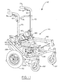
- is a perspective view of a wheelchair containing a tiltable seat according to the present invention.
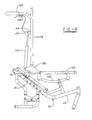
- Fig. 2
- is a side elevational view showing the seat in an upright position.
- Fig. 3
- is a side elevational view showing the seat in a tilted position.
- Fig. 4
- is a top plan view taken in line 4-4 of
Fig. 2 showing the wheelchair frame assembly, the curvilinear support member, cross frame members, and the like. - Fig. 5
- is a perspective view showing the curvilinear support member connected to a seat bottom member, and
Fig. 6 is a perspective view of the gear rack. - Fig. 7
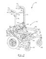
- is a perspective view of a wheelchair containing a tiltable seat according to the present invention, a recessed seat, and marking elements which show the tilt angle of the seat.
- Fig. 8
- is a side elevational view of a wheelchair having a reclinable back member as well as a tiltable seat. The seat is shown at 0 degrees tilt and 90 degrees recline.
- Fig. 9
- is a side elevational view showing the seat tilted 0 degrees and 180 degrees recline.
- Figure 10
- is a perspective view of the tiltable and reclinable wheelchair showing a recliner bracket plate, recliner cylinders, recliner release handles, and a pull cable release grip.
- A tiltable seat according to the present invention can be utilized on any conventional or typical wheelchair such as a powered wheelchair but desirably is utilized in association with a manual wheelchair. Wheelchair 10 contains
mainframe 12 which has afront portion 14 and arear portion 16 upwardly inclined at a predetermined angle with respect to the horizontal. The front end offrame front portion 14 contains apivotal caster assembly 32 so thatwheelchair 10 can be readily pivoted and turned in any desirable direction.Rear frame portion 16 contains afront leg 18A and arear leg 18B depending therefrom which each containing a plurality of apertures 22 so thatwheel 30 can be attached thereto at any desirable height through the utilization of a suitable or conventional wheel attachment structure. Such structure, which can be a bracket, can contain a plurality of slots or recesses so that the wheel axle can be located at any horizontal position. Connected tofront frame portion 14 is support arm orclevis 24, which at the upper end thereof can have any convenient element such asroller 26 to allow a seat support member to slide or travel there over while being supported. - While various components will be shown by the drawings as being located on the right-hand side or left-hand side of the wheelchair, it is to be understood that such components exist on both sides of the chair and are very similar, and usually identical.
-
Gear rack 40 is connected torear portion 16 of the frame through anysuitable fastener 42 such as a cap screw. The gear rack can generally be of any shape or configuration such as a rectangle, a flange, a channel, or an annular tube 44 having along one side thereofrecesses 46 withteeth 48 located there between. The recesses and teeth as shown inFig. 6 , generally extend along the entire length of the gear rack. Slidablyengaging gear rack 40 isbracket 50 which generally can be of any size or shape and has anaperture 52 for receivingbracket pin 54 which pivotally receives a seat extension link discussed herein below in greater detail.Slidable bracket 50 can be operated manually as shown or by power (not shown). When operated manually,gear rack bracket 50 also receivespull cable 60 which is connected at the other end to a handgrip. The pull cable is received by spring loadedhousing 56 of the gear rack bracket so that a projection, not shown, is always pressed or forced into arecess 46 of the gear rack thereby maintainingbracket 50 in a set or fixed position. -
Seat 70 of the wheelchair containsback member 72 andbottom member 82 which constitutes a frame for the seat and exist on each lateral side of the seat as shown inFig. 1 .Back member 72 can be a metal tube or any other suitable article containing ahandle 73 for gripping by an individual as well as pullcable release grip 74. Application of an upward pressure to the release grip or a squeezing pressure thereto by an individual causes pullcable 60 to be pulled upwardly along the back member and at its other end pulls the projection out ofgear rack recess 46 so that the gear rack bracket can then be manually slid upwardly or downwardly and repositioned in another recess upon release ofgrip 74. When operated by power, not shown,bracket 50 can be moved in a number of different ways such as by a hydraulic piston connected to the frame, or bygear rack 40 being a worm gear meshing with teeth within the bracket. The back member also contains atransverse tilt bar 76, which in addition to handle 72, can be grasped by an individual to either push a manual wheelchair or to cause the seat to be manually tilted backward or forward. The height of the tilt bar can be adjusted by positioning the same in any of a plurality ofapertures 77 which extend along the length of the back member. Located at a lower portion ofback member 72 is seat backpin 78 which in part connects seat back 72 toconnection plate 90. Typically, at the bottom end of the seat back,hinge pin 79 pivotally connects the seat back member toconnection plate 90. -
Rear portion 16 offrame 12 optionally can contain markingelements 17, which correspond to the degree thatseat 70 is tiltable, as in a forward or backward direction. The seat may be tilted in a range generally of from about 10 degrees forward to about 45 degrees rearward.Markings 17 can be in the form of a decal, etching, scoring, or any suitable graduation marks or such. Themarkings 17 are capable of being lined up with asuitable marking point 19 located ongear rack bracket 50. Markingpoint 19 can also be a decal, etching, scoring, or other suitable locating element. - Marking
point 19 in association withmarkings 17 readily allow the seat to be set at a desirable degree of tilt such as that recommended by physical therapist or other medical person. This ability imparts several advantages to a patient, such as ease of breathing, relief of pressure, improved ability to swallow, and improved posture. -
Seat bottom member 82 can be a metal tubular seat frame member generally located on the lateral sides of the seat and contain various fittings and the like upon which a seat, a seat cushion, and the like can be placed. At the back end ofbottom members 82 are generally located two bolts, i. e.,front bolt 84 andrear bolt 86, which through corresponding apertures of the bottom membersecure connection plate 90 to the bottom member. -
Connection plate 90 serves to fixedly secure seat backmember 72 to seatbottom member 82 as an integral unit such as at an angle of 90 degrees with respect to each other. Moreover,connection plate 90 permits backmember 72 to be fixedly secured to the bottom member at a number of recline positions other than 90 degrees, for example, up to a reclining angle of about 30 degrees at generally 10 degree increments. This is accomplished through the utilization ofapertures 98A, 98B, and 98C. Thus, in lieu of utilizingseat bottom bolt 86 in the position indicated inFig. 2 , the bolt can be inserted in aperture 98C to recline the back an additional 10 degrees, i. e., a 100 degree angle with respect toseat bottom member 82. Similarly, angles of an additional 20 degrees or 30 degrees can be obtained by utilizingaperture 98B or 98A, respectively, to achieve an overall angle of 110 and 110 degrees respectively with regard to the seat bottom member. - The utilization of spring loaded
latch 92 permits seat backmember 72 to be quickly disengaged from an integral connection withbottom member 82 and lowered to essentially a horizontal position when not in use.Spring latch 92 is pivotally attached toconnection plate 90 throughlatch pivot pin 94. Whenwheelchair 10 is not in use, latch 92 can be pressed downwardly thereby freeing seat backpin 78 from mechanical engagement with a recess inlatch 92 whereby the seat back can be lowered to reside over the seat bottom. Obviously, when the seat back is in use, it is utilized in an upward position as shown inFig. 2 . The lower portion of seat backmember 72 which hinges abouthinge pin 79 is prevented from moving backward by the engagement thereof with a stop block, not shown, which is secured toconnection plate 90 through the utilization ofstop block bolts - An important aspect of the present invention is the utilization of
curvilinear member 110 in conjunction with frame support or clevisarm 24.Curvilinear support member 110, of course, is generally in the form of an arc of a circle. The radius of the arc, as noted above, terminates in an end point or center point which is generally located within the vicinity of the center of gravity of a hypothetical or composite person. Such a person is defined as being representative of an average of a variety of different sized and shaped people. The location of the center of gravity of the hypothetical person is about 19,05 cm (7.5 inches) forward ofback members bottom members 82. A different center of gravity location will exist ifcurvilinear support member 110 is tailor made for a specific person or a class of persons (e. g., small or large) since the radius of the support member will be different. The radius end point ofsupport member 110 is generally located within 10,16 or 7,62 cm (4 or 3 inches), desirably within 5,08 cm (2 inches), and preferably within 2,54 cm (1 inch) of the center of gravity of the hypothetical or composite person or other person. During tilting ofseat 70, the radius end point or center point ofsupport member 110 will generally reside within a circle and more preferably along a horizontal line having, respectively, a diameter or length of less than about 10,16; 7,62 or 5,08 cm (4, 3, or 2 inches), or preferably less than about 2.54 cm (one inch) from the center of gravity location. -
Curvilinear support member 110 is connected to generallyhorizontal foot member 112 which in turn is connected toleg member 114 attached to the underside ofbottom seat member 82. In order to assure lateral rigidity of the curvilinear support members, each left and right side member is connected to each other throughfront cross member 116 andrear cross member 118 as shown inFig. 4 . Similarly, lateral stability of the main frame is accomplished by connecting left and right sides ofmain frame 12 to each other through framefront cross member 28 and framerear cross member - Recessed seat bottom member 71 is located on
foot members 112 and/or front andrear cross members Figs. 1 ,2 and3 . The recessed seat is generally located from about 3,81 cm (1-1/2 inches) to about 7,62 cm (3 inches), and preferably from about 5,08 cm (2 inches) to about 6,35 cm (2-1/2 inches) belowbottom member 82. If the seat were located higher or lower, the center of gravity of an individual in the seat would often change. The recessed seat offers better stability to the user and allows one to be more comfortable and closer to framemember 14. The recessed seat also compensates for cushions, thick or thin, that can be utilized withwheelchair 10. - A key aspect of the present invention is that the curvilinear member has a shape such that when
seat 70 is rotated on said member oversupport arm 24, the center of gravity of the hypothetical or composite person, etc., seated in the wheelchair is a point, located a specific distance forward of the back member and a specific distance above the bottom member, which point is generally maintained in a fixed position or relatively small locus as the seat is tilted backward or forward. Such locus is generally an area as noted above. - Extending generally from the vicinity of the junction of the back member and the bottom member such as from the rear of
bottom seat member 82 isrigid link 120 which is pivotally attached to gearrack bracket 50.Gear rack 40 has an inclination which generally coincides with a straight line through or approximates an arc created bybracket pin 54 as the seat is moved from an upright position as shown inFig. 2 to a rearward position as shown inFig. 3 . Thus, the angle of gear rack will vary depending upon the length oflink 120 with the angle being more vertical for longer links (not preferred) and more longitudinal with regard to shorter link (preferred) lengths. Upon gripping pullcable release grip 74,seat 70 can be tilted as a unit rearwardly either through the use ofhandle 73 ortransverse tilt bar 76. Generally, the seat can be tilted up to about 50 or 60 degrees. Rearward tilting of the seat causesbracket 50 to slide downwardly along gear rack 44 and at the same time causeseat bottom member 82 to move forwardly withcurvilinear support member 110 moving forward alongroller 26. The combination of the inclination ofrack 40 and the radius of curvature ofcurvilinear support member 110 riding uponsupport arm 24 thus causes the center of gravity of a hypothetical or composite person, etc., seated withinseat 70 to be substantially maintained as the seat bottom is moved forwardly and the back tilted rearwardly. In other words, the angle of inclination of the gear rack is such that the gear rack is parallel to the line that coincides withbracket pin 54 at both the maximum and minimum tilt of the seat when the seat is rotated about the center of gravity of a person independent of theframe 12. - Another preferred embodiment relates to a tilt and recline seat in which seat back
member 72 is reclinable. In this embodiment,connection plate 90 is replace withrecliner bracket plate 130 as can be generally seen in at leastFigs 9 ,10 and 11. Seat backmember 72 is hingedly or rotatably attached torecliner bracket plate 130 making seat back member reclinable. Arecliner cylinder 140 at one end is operatively and fixedly attached to a rear portion ofrecliner bracket plate 130 and at the opposite end to seat backcylinder mounting bracket 144 throughcylinder release bracket 142. Seat backcylinder mounting bracket 144 is mounted on seat backmember 72.Back member 72 can have ahandle 73 as seen inFig. 1 , or astroller handle 150 such as those seen inFigs. 8 ,9 and10 . No matter what type of handle is used, pullcable release grip 74 and recliner release handle 146 are fixedly attached thereto or to seat backmember 72. Preferably recliner release handle 146 is mounted under stroller handle 150 so that applying pressure on the recliner release handle lever causesrecliner cable 148 to allowrecliner cylinder 140 to be released thereby allowing the seat back member to be reclined from a range of about 90 degrees to about 180 degrees in relation toseat bottom member 82. Pullcable release grip 74 is preferably mounted on the inside of stroller handle 150 so that upon applying pressure thereto the wheelchair can be tilted as described herein above. - Although
recliner cable 148 can run from recliner release handle 146 tocylinder release bracket 142 on the same side of the wheelchair, it is preferred thatrecliner cable 148 is attached to a recliner release handle and cylinder release bracket on opposite side of the wheelchair to prevent kinking or binding ofrecliner cable 148. - Generally two
recliner cylinders 140 are utilized, but any number will suffice. The cylinders are preferably gas-locking cylinders, but oil or other fluid type cylinders can also be used. The gas pressure counteracts the weight of the person in the chair and thus aids an attendant raising the seat back member. - The following table is only an example of the possible recline angle ranges at various degrees of tilt for a specific wheelchair geometry as shown in
Figs. 8 ,9 , and10 . It is foreseeable that wheelchairs with other dimensions could be made to tilt and recline at other angles and ranges.TILT ANGLE (relative to the floor) MINIMUM RECLINE ANGLE (relative to the seat) MAXIMUM RECLINE ANGLE (relative to the seat) -10 deg (forward) 90 deg 180 deg -5 deg (forward) 90 deg 180 deg 0 deg 90 deg 180 deg 5 deg 90 deg 168 deg 10 deg 90 deg 158 deg 15 deg 90 deg 149 deg 20 deg 90 deg 141 deg 25 deg 90 deg 134 deg 30 deg 90 deg 126 deg 35 deg 90 deg 119 deg 40 deg 90 deg 112 deg 45 deg 90 deg 106 deg - It is noted that as the tilt angle increases, the maximum possible recline angle is reduced due to chair geometry.
- From the above description, it should be understood that the wheelchair seat embodiments of
Figs. 8 ,9 and10 of the present invention are both tiltable and reclinable. - Although the constant center of gravity tilt seat of the present invention has been described in association with a preferred embodiment having a manual tilt, as well as with a manual tilt and manual recline seat back, it can use a power tilt and also a power recline seat back. The tilt seat, as well as the tilt and recline seatback seat, can also be utilized with any wheelchair base including power wheelchairs, i. e., powered by one or more batteries, as well as with different types of wheel drives, for example, a front-wheel drive, a mid-wheel drive, or a rear-wheel drive. All that is required is
seat 70 and related structural components such ascurvilinear support member 110 andgear rack 40 be attached to the frame work of such vehicles in a manner as shown and described herein. Moreover, with regard to manual wheelchairs such as that shown in the drawings, different wheel sizes and locations can be utilized such as where the front wheels have a large diameter and the rear wheels have a smaller diameter. - While in accordance with the patent statutes the best mode and preferred embodiment have been set forth, the scope of the invention is not limited thereto, but rather by the scope of the attached claims.
Claims (14)
- A wheelchair (10), comprising;
a frame (12);
a tiltable seat (70) operatively connected to said frame (12), said seat (70) having a back member (72) connected to a bottom member (82);
and a curvilinear support member (110) connected to said seat bottom member (82) and operatively and movably engaging said frame (12); characterized by
a gear rack (40) fixedly connected to said frame (12), said gear rack (40) operatively connected to said seat (70) for controlling the tilting of said seat (70);
whereby said curvilinear support member (110) has a center region spaced apart from and located above said frame (12) about which said seat (70) tilts. - A wheelchair (10) according to Claim 1, comprising a bracket (50) slidable on said gear rack (40), said bracket (50) causing said seat (70) to tilt rearward or forward as said bracket (50) is moved respectively in a first direction or in a second direction along said gear rack (40) so that said seat (70) substantially tilts about said center region.
- A wheelchair (10) according to Claim 1 or 2, characterized in that said frame (12) has a support arm (24), and said curvilinear support member (110) movably engages said support arm (24).
- A wheelchair (10) according to Claim 3, characterized in that said seat (70) is manually tiltable, wherein said slidable bracket (50) has a cable (60) connected thereto, and wherein said cable (60) is capable of causing said slidable bracket (50) to engage or disengage said gear rack (40) at different angles of tilt.
- A wheelchair (10) according to anyone of Claims 1 to 4, characterized in that said seat (70) is tiltable by power.
- A wheelchair (10) according to Claim 1, wherein said wheelchair is a manual wheelchair.
- A wheelchair (10) according to Claim 1, wherein said wheelchair is a power wheelchair.
- A wheelchair (10) according to anyone of claims 2 to 7, characterized in that said gear rack is inclined and said bracket (50) is operatively connected to the rear portion (16) of said seat, said bracket (50) causing seat (70) to tilt backward or forward as said bracket (50) is respectively slid downward or upward along said gear rack (40) so that said center of gravity is substantially maintained.
- A wheelchair (10) according to Claim 8, wherein said gear rack (40) contains a plurality of releasable engagement positions engagable by said slidable bracket (50) to maintain said seat (70) in a desired tilt position.
- A wheelchair (10) according to anyone of Claims 1 to 9, characterized in that said curvilinear support member (110) has a radius, the center point of which is within 10,16 cm (4 inches) of the center of gravity of a person when seated in said seat (70);
and marking elements (17) on said frame (12) which correspond to the degree of tilt of said seat bottom (82). - A wheelchair (10) according to Claim 10, characterized in that said gear rack bracket (50) has a marking point (19) thereon to indicate the degree of tilt of said seat bottom (82).
- A wheelchair (10) according to Claim 11, characterized in that said seat back member (72) is reclinable.
- A wheelchair (10) according to Claim 12, including a recliner bracket plate (130), said recliner bracket plate (130) being hingedly attached to said seat back member (72) and fixedly attached to said seat bottom member (82) so that said seat back member (72) can be reclined from a range of about 90 degrees to about 180 degrees in relation to said seat bottom member (82).
- A wheelchair (10) according to Claim 13, wherein said seat back member (72) is reclinable by power.
Applications Claiming Priority (3)
| Application Number | Priority Date | Filing Date | Title |
|---|---|---|---|
| US09/188,851 US6126186A (en) | 1998-11-09 | 1998-11-09 | Constant center of gravity tilt seat of a wheelchair |
| US09/408,906 US6206393B1 (en) | 1998-11-09 | 1999-09-29 | Constant center of gravity tilt seat of a wheelchair |
| EP99971694A EP1128793B9 (en) | 1998-11-09 | 1999-11-03 | Constant center of gravity tilt seat of a wheelchair |
Related Parent Applications (2)
| Application Number | Title | Priority Date | Filing Date |
|---|---|---|---|
| EP99971694.7 Division | 1999-11-03 | ||
| EP99971694A Division EP1128793B9 (en) | 1998-11-09 | 1999-11-03 | Constant center of gravity tilt seat of a wheelchair |
Publications (3)
| Publication Number | Publication Date |
|---|---|
| EP2039334A2 EP2039334A2 (en) | 2009-03-25 |
| EP2039334A3 EP2039334A3 (en) | 2009-09-30 |
| EP2039334B1 true EP2039334B1 (en) | 2013-01-02 |
Family
ID=22694806
Family Applications (1)
| Application Number | Title | Priority Date | Filing Date |
|---|---|---|---|
| EP09150240A Expired - Lifetime EP2039334B1 (en) | 1998-11-09 | 1999-11-03 | Constant center of gravity tilt seat of a wheelchair |
Country Status (5)
| Country | Link |
|---|---|
| US (2) | US6126186A (en) |
| EP (1) | EP2039334B1 (en) |
| AT (1) | ATE427091T1 (en) |
| DE (1) | DE69940675D1 (en) |
| HK (1) | HK1128612A1 (en) |
Families Citing this family (68)
| Publication number | Priority date | Publication date | Assignee | Title |
|---|---|---|---|---|
| NL1012548C2 (en) * | 1999-07-09 | 2001-01-10 | Mediquip Holland B V | Wheelchair. |
| AU1491001A (en) * | 1999-11-15 | 2001-05-30 | Freedom Designs Incorporated | Improved wheelchair with tilting seat |
| US6588792B1 (en) * | 2000-05-31 | 2003-07-08 | Sunrise Medical Hhg Inc. | Method of programming and operating tilt and recline functions in a wheelchair |
| US6409265B1 (en) | 2000-05-31 | 2002-06-25 | Sunrise Medical Hhg, Inc. | Tilting and reclining wheelchair |
| US6715784B2 (en) | 2000-05-31 | 2004-04-06 | Sunrise Medical Hhg Inc. | Method programming and operating a wheelchair having tilt and recline functions |
| US6976699B2 (en) * | 2000-05-31 | 2005-12-20 | Sunrise Medical Hhg Inc. | Coordinated articulation of wheelchair members |
| JP2002145139A (en) * | 2000-11-09 | 2002-05-22 | Fukashi Uragami | Running carrier |
| US6428029B1 (en) * | 2001-02-09 | 2002-08-06 | Advanced Mobility Systems Corporation | Wheelchair frame |
| DE20112583U1 (en) * | 2001-08-01 | 2001-12-06 | Britax Teutonia Kinderwagen | stroller |
| US6799770B2 (en) | 2002-03-26 | 2004-10-05 | Jack Patrick | Reclinable wheelchair |
| GB0207144D0 (en) * | 2002-03-27 | 2002-05-08 | Specmat Ltd | Wheelchairs |
| TW549080U (en) * | 2002-04-03 | 2003-08-21 | Aidc Aerospace Ind Dev Corp | Improved structure of submerging-type seat mat and back plate |
| US20060131833A1 (en) * | 2003-03-27 | 2006-06-22 | Specmat Limited | Wheelchairs |
| US8474848B2 (en) * | 2003-03-31 | 2013-07-02 | Sunrise Medical (Us) Llc | Personal mobility vehicle with tiltable seat |
| US7007965B2 (en) * | 2003-03-31 | 2006-03-07 | Sunrise Medical Hhg Inc. | Center-of-gravity tilt-in-space wheelchair |
| US20050029855A1 (en) * | 2003-03-31 | 2005-02-10 | Hanson Wayne H. | Dynamic seating system for personal mobility vehicle |
| SE0301293L (en) * | 2003-05-05 | 2004-03-09 | Arjo Hospital Equipment Ab | Patient chair with seat slidable in height |
| US20040222611A1 (en) * | 2003-05-06 | 2004-11-11 | Richard Fenwick | Programmable multifunctional air support reclining and tilting wheelchair |
| US20050046129A1 (en) * | 2003-08-15 | 2005-03-03 | Antonishak Stephen J. | Constant center of gravity lift and tilt mechanisms for a wheelchair seat |
| US7014204B2 (en) * | 2003-10-06 | 2006-03-21 | Amg Medical Inc. | Rocking wheelchair |
| US7296856B2 (en) * | 2003-10-08 | 2007-11-20 | Pride Mobility Products Corporation | Reclining seat with movable back support |
| US20050279540A1 (en) * | 2004-06-07 | 2005-12-22 | Wisner Donald W | Adjustable wheelchair |
| DE102004045388B4 (en) * | 2004-09-18 | 2006-10-19 | Otto Bock Healthcare Gmbh | Vehicle with tilt-adjustable driver's seat |
| US20060076747A1 (en) * | 2004-10-08 | 2006-04-13 | Sunrise Medical Hhg Inc. | Wheelchair suspension system |
| US7360841B2 (en) * | 2004-10-20 | 2008-04-22 | Pride Mobility Products Corporation | Articulating leg rest for a wheelchair |
| EP1814502A1 (en) * | 2004-10-29 | 2007-08-08 | R82 A/S | Comfort wheelchair |
| US7845665B2 (en) * | 2005-03-30 | 2010-12-07 | Jaimie Borisoff | Wheelchair |
| GB2448977B (en) * | 2005-07-06 | 2009-11-18 | Advanced Engineering Tech Ltd | Grass treatment device |
| US20070102615A1 (en) * | 2005-10-21 | 2007-05-10 | Permobil Ab | Seat tilt apparatus for a wheelchair |
| GB0601355D0 (en) * | 2006-01-24 | 2006-03-01 | Michel David | Height adjustment |
| GB2434778A (en) * | 2006-02-06 | 2007-08-08 | Michael Jeffrey Spindle | Wheelchair with adjustable ride height |
| US8460223B2 (en) * | 2006-03-15 | 2013-06-11 | Hill-Rom Services Pte. Ltd. | High frequency chest wall oscillation system |
| US8944454B2 (en) * | 2007-10-01 | 2015-02-03 | Pride Mobility Products Corporation | Dual-track tilt mechanism |
| US20100038880A1 (en) * | 2008-08-15 | 2010-02-18 | Bagg Christian Peter Edward | Modular and/or configurable wheelchair apparatus |
| US8162346B2 (en) * | 2008-12-09 | 2012-04-24 | Purdue Carole | Mobile chair assembly |
| WO2010080638A1 (en) * | 2008-12-18 | 2010-07-15 | Invacare Corporation | Wheelchair |
| AU2010319339B2 (en) * | 2009-11-15 | 2014-09-04 | Invacare Corporation | Wheelchair |
| US8322741B2 (en) * | 2010-03-05 | 2012-12-04 | Pride Mobility Products Corporation | Apparatus for tilting a wheelchair seat |
| US8919797B2 (en) | 2010-03-16 | 2014-12-30 | Invacare Corp. | Wheelchair seat assembly |
| US8584286B2 (en) | 2010-04-27 | 2013-11-19 | Ec Service Inc. | Systems and methods for providing a self deflating cushion |
| US8931583B2 (en) | 2010-06-24 | 2015-01-13 | Invacare Corporation | Wheelchair |
| US9717340B2 (en) | 2010-09-13 | 2017-08-01 | Tropitone Furniture Co., Inc. | Adjustable seating and furniture |
| US8534758B2 (en) | 2010-09-13 | 2013-09-17 | Tropitone Furniture Co., Inc. | Reclinable seating apparatus and method |
| US8646795B2 (en) | 2010-11-10 | 2014-02-11 | Invacare Corporation | Reclining seat |
| US8516630B2 (en) | 2010-12-08 | 2013-08-27 | University Of Massachusetts | Convertible wheelchair |
| US20120161484A1 (en) * | 2010-12-28 | 2012-06-28 | Taiwan An I Co., Ltd. | Wheelchair tilting mechanism |
| US20120292877A1 (en) | 2011-05-17 | 2012-11-22 | Johansson Paul J | Mobile rocking patient chair and method of use |
| US9408763B2 (en) * | 2012-05-04 | 2016-08-09 | Carole PURDUE | Wheelchair with user controlled tilt mechanism |
| DK177506B1 (en) * | 2012-05-08 | 2013-08-12 | Wolturnus As | Multi-adjustable wheelchair with closed frame and impact-resistant front suspension |
| US9364378B2 (en) * | 2012-07-31 | 2016-06-14 | Invacare International Sarl | Wheelchair including a collapsible and/or angle adjustable backrest frame |
| WO2014072768A1 (en) * | 2012-11-06 | 2014-05-15 | Invacare International Sarl | Wheelchair including a tiltable seat |
| WO2014138128A1 (en) | 2013-03-04 | 2014-09-12 | Ki Mobility | Tilt-in-space wheelchair using multiple controlling paths |
| JP6445564B2 (en) * | 2013-09-06 | 2018-12-26 | アル リハブ アーエス | Wheelchair removable coupling bar |
| WO2016041087A1 (en) | 2014-09-18 | 2016-03-24 | Miller Greg Bruce | Adjustable chair |
| US9682603B2 (en) | 2014-10-10 | 2017-06-20 | Max Mobility, Llc | System and method for adjusting a wheelchair seat |
| US9073399B1 (en) | 2014-10-10 | 2015-07-07 | Max Mobility, Llc | System and method for adjusting a wheelchair seat |
| EP3034056B1 (en) * | 2014-12-18 | 2017-11-29 | Permobil AB | Seat arrangement and electrically powered wheelchair comprising the same |
| US10702431B1 (en) * | 2016-02-25 | 2020-07-07 | Ki Mobility | Keyed and indexed embossed tube and taper lock system |
| US9987179B2 (en) | 2016-03-24 | 2018-06-05 | Freedom Designs, Inc. | Adjustable wheelchair arrangements |
| CN106038120A (en) * | 2016-07-12 | 2016-10-26 | 天津市鑫成新科贸有限公司 | Wheelchair pedal driven to lift by rack |
| US10772774B2 (en) | 2016-08-10 | 2020-09-15 | Max Mobility, Llc | Self-balancing wheelchair |
| US10624803B2 (en) | 2017-12-01 | 2020-04-21 | IdeaShare Designs LLC | Tilting manual wheelchair |
| DE102018113346A1 (en) | 2018-06-05 | 2019-12-05 | Sunrise Medical Gmbh | Backrest and chair, especially for a wheelchair |
| US10918543B2 (en) * | 2018-09-04 | 2021-02-16 | Joseph Shea | Tracked chair |
| CA3016506A1 (en) * | 2018-09-05 | 2020-03-05 | Raz Design Inc. | A tilt lock mechanism for a tilting wheelchair seat |
| US11712382B2 (en) | 2019-10-01 | 2023-08-01 | Christiana Care Health System, Inc. | Wheelchair with dynamic occupant-tilt feature |
| US11331232B1 (en) | 2021-11-30 | 2022-05-17 | Marvin Joseph Glover | Wheelchair improvement kit and manual wheelchair |
| TWI818759B (en) * | 2022-10-05 | 2023-10-11 | 長庚學校財團法人長庚科技大學 | wheelchair |
Family Cites Families (30)
| Publication number | Priority date | Publication date | Assignee | Title |
|---|---|---|---|---|
| US160624A (en) * | 1875-03-09 | Improvement in tiltlng-chairs | ||
| US137091A (en) * | 1873-03-25 | Improvement in tilting-chairs | ||
| US1438667A (en) * | 1922-08-26 | 1922-12-12 | Schops Hermann | Rocking chair |
| DE405542C (en) * | 1923-09-05 | 1924-11-05 | Manufactures De Prod Chim Du N | Spirlet ore roast furnace |
| US1970577A (en) * | 1931-05-21 | 1934-08-21 | Edward P Farrell | Adjustable chair |
| GB509033A (en) * | 1936-10-17 | 1939-07-06 | Matthew Harvey & Company Ltd | An improved adjustable seat for automobiles and the like |
| FR823912A (en) * | 1937-07-05 | 1938-01-28 | Accessoires En Tube Pour Autom | Reclining seat back, especially applicable to vehicles |
| IL41737A (en) * | 1973-03-08 | 1975-04-25 | Danziger U | Easy-transfer wheelchair |
| JPS5628714A (en) * | 1979-08-20 | 1981-03-20 | Tokico Ltd | Locking chair |
| NL8601457A (en) * | 1986-06-05 | 1988-01-04 | Huka Bv Developments | WHEELCHAIR WITH TILT SEAT. |
| FR2604131B1 (en) * | 1986-09-19 | 1990-02-02 | Cousin Cie Ets A & M Freres | CURVED CURVED SLIDES |
| US4966379A (en) * | 1987-10-19 | 1990-10-30 | Mulholland Designs, Inc. | Reclinable wheelchair |
| US4893827A (en) * | 1988-08-31 | 1990-01-16 | Gunnell, Inc. | Chair construction for incapacitated persons |
| US4957302A (en) * | 1989-02-15 | 1990-09-18 | Eidos Corporation | Worker support apparatus |
| DE3921384C1 (en) * | 1989-06-29 | 1991-02-14 | Erfi Produktions-Gmbh & Co Kg, 8637 Ahorn, De | |
| US5044647A (en) * | 1989-11-17 | 1991-09-03 | Folio Products, Inc. | Stabilized reclining wheelchair seat |
| EP0557440B1 (en) * | 1990-11-14 | 1998-07-15 | Invacare Corporation | Attended to self-propelled convertible pivoting wheelchair |
| US5137295A (en) * | 1991-02-28 | 1992-08-11 | Peek Gregory A | Wheelchair with anti-tip assembly |
| US5154438A (en) * | 1991-09-30 | 1992-10-13 | Barclay Hugh W | Tilting and folding wheelchair |
| US5297021A (en) * | 1992-11-16 | 1994-03-22 | Koerlin James M | Zero shear recliner/tilt wheelchair seat |
| US5624159A (en) * | 1993-05-11 | 1997-04-29 | Vess Chairs, Inc. | Adaptive seating device for diagnostic testing |
| US5333887A (en) * | 1993-11-16 | 1994-08-02 | Joe Sharp | Wheelchair/gurney |
| FR2717377B1 (en) * | 1994-03-18 | 1996-06-21 | Idc Isolateur Denominateur | Lifting device for stand-up wheelchair and wheelchair by application. |
| US5458349A (en) * | 1994-06-30 | 1995-10-17 | Mung-Tung; Wang | Multi-function electric wheel-chair |
| NO300754B1 (en) * | 1994-10-14 | 1997-07-21 | Handicare Ind As | Adjustable chair |
| US6050642A (en) * | 1996-05-13 | 2000-04-18 | Erb; Scott C. | Multi-direction reclining and stretching chair |
| US5797252A (en) * | 1996-05-13 | 1998-08-25 | Deere & Company | Height of cut adjustment mechanism |
| US5884928A (en) * | 1996-07-23 | 1999-03-23 | Papac; James B. | Wheelchair |
| US5967609A (en) * | 1996-11-18 | 1999-10-19 | Hwe, Inc. | Reclining chair with guide rail system |
| US6056363A (en) * | 1997-12-29 | 2000-05-02 | Maddox; Lee W. | Reclining computer chair apparatus |
-
1998
- 1998-11-09 US US09/188,851 patent/US6126186A/en not_active Expired - Lifetime
-
1999
- 1999-09-29 US US09/408,906 patent/US6206393B1/en not_active Expired - Lifetime
- 1999-11-03 DE DE69940675T patent/DE69940675D1/en not_active Expired - Lifetime
- 1999-11-03 AT AT99971694T patent/ATE427091T1/en not_active IP Right Cessation
- 1999-11-03 EP EP09150240A patent/EP2039334B1/en not_active Expired - Lifetime
-
2009
- 2009-09-07 HK HK09108173.3A patent/HK1128612A1/en not_active IP Right Cessation
Also Published As
| Publication number | Publication date |
|---|---|
| DE69940675D1 (en) | 2009-05-14 |
| US6126186A (en) | 2000-10-03 |
| EP2039334A3 (en) | 2009-09-30 |
| EP2039334A2 (en) | 2009-03-25 |
| US6206393B1 (en) | 2001-03-27 |
| ATE427091T1 (en) | 2009-04-15 |
| HK1128612A1 (en) | 2009-11-06 |
Similar Documents
| Publication | Publication Date | Title |
|---|---|---|
| EP2039334B1 (en) | Constant center of gravity tilt seat of a wheelchair | |
| EP1613524B1 (en) | Center-of-gravity tilt-in-space wheelchair | |
| CA2488913C (en) | Multi adjustable chair | |
| US6276704B1 (en) | Adjustable wheelchair having a tilting and reclining seat | |
| EP1789004B9 (en) | Personal mobility vehicle with tiltable seat | |
| US5011175A (en) | Wheelchair | |
| US3379450A (en) | Adjustable wheelchair device | |
| US5044647A (en) | Stabilized reclining wheelchair seat | |
| US5366036A (en) | Power stand-up and reclining wheelchair | |
| US5865457A (en) | Wheeled health care chair | |
| US3618968A (en) | Patient-operated wheelchair | |
| AU615881B2 (en) | A wheelchair apparatus | |
| AU736690B2 (en) | A constant center of gravity tiltable chair of a wheelchair | |
| US4834411A (en) | Apparatus for reclining wheelchairs for shampooing chair occupants | |
| US4830567A (en) | Portable wheelchair lift | |
| EP1128793B9 (en) | Constant center of gravity tilt seat of a wheelchair | |
| EP1286638A1 (en) | A chair for handicapped or disabled persons | |
| EP0348171A2 (en) | Standing frame assembly for use with wheelchair | |
| CA2546741C (en) | Constant center of gravity tilt seat of a wheelchair | |
| GB2048791A (en) | Wheelchairs | |
| EP1166741B1 (en) | Lifting and transport apparatus for disabled persons | |
| JP3227598B2 (en) | Wheelchair equipment | |
| US20020030350A1 (en) | User-propelled geriatric chair | |
| GB2369566A (en) | Support seat for the disabled | |
| JP4633453B2 (en) | Relaxed wheelchair with electric stand-up assist function |
Legal Events
| Date | Code | Title | Description |
|---|---|---|---|
| PUAI | Public reference made under article 153(3) epc to a published international application that has entered the european phase |
Free format text: ORIGINAL CODE: 0009012 |
|
| 17P | Request for examination filed |
Effective date: 20090108 |
|
| AC | Divisional application: reference to earlier application |
Ref document number: 1128793 Country of ref document: EP Kind code of ref document: P |
|
| AK | Designated contracting states |
Kind code of ref document: A2 Designated state(s): AT BE CH CY DE DK ES FI FR GB GR IE IT LI LU MC NL PT SE |
|
| RIN1 | Information on inventor provided before grant (corrected) |
Inventor name: JUCHEM, CARL M. Inventor name: MASCARI, NICHOLAS A. |
|
| PUAL | Search report despatched |
Free format text: ORIGINAL CODE: 0009013 |
|
| AK | Designated contracting states |
Kind code of ref document: A3 Designated state(s): AT BE CH CY DE DK ES FI FR GB GR IE IT LI LU MC NL PT SE |
|
| REG | Reference to a national code |
Ref country code: HK Ref legal event code: DE Ref document number: 1128612 Country of ref document: HK |
|
| AKX | Designation fees paid |
Designated state(s): AT BE CH CY DE DK ES FI FR GB GR IE IT LI LU MC NL PT SE |
|
| 17Q | First examination report despatched |
Effective date: 20100907 |
|
| GRAP | Despatch of communication of intention to grant a patent |
Free format text: ORIGINAL CODE: EPIDOSNIGR1 |
|
| GRAS | Grant fee paid |
Free format text: ORIGINAL CODE: EPIDOSNIGR3 |
|
| GRAA | (expected) grant |
Free format text: ORIGINAL CODE: 0009210 |
|
| AC | Divisional application: reference to earlier application |
Ref document number: 1128793 Country of ref document: EP Kind code of ref document: P |
|
| AK | Designated contracting states |
Kind code of ref document: B1 Designated state(s): AT BE CH CY DE DK ES FI FR GB GR IE IT LI LU MC NL PT SE |
|
| REG | Reference to a national code |
Ref country code: GB Ref legal event code: FG4D |
|
| REG | Reference to a national code |
Ref country code: AT Ref legal event code: REF Ref document number: 591154 Country of ref document: AT Kind code of ref document: T Effective date: 20130115 Ref country code: CH Ref legal event code: EP |
|
| REG | Reference to a national code |
Ref country code: IE Ref legal event code: FG4D |
|
| REG | Reference to a national code |
Ref country code: DE Ref legal event code: R096 Ref document number: 69944562 Country of ref document: DE Effective date: 20130228 |
|
| REG | Reference to a national code |
Ref country code: HK Ref legal event code: GR Ref document number: 1128612 Country of ref document: HK |
|
| REG | Reference to a national code |
Ref country code: AT Ref legal event code: MK05 Ref document number: 591154 Country of ref document: AT Kind code of ref document: T Effective date: 20130102 |
|
| REG | Reference to a national code |
Ref country code: NL Ref legal event code: VDEP Effective date: 20130102 |
|
| PG25 | Lapsed in a contracting state [announced via postgrant information from national office to epo] |
Ref country code: ES Free format text: LAPSE BECAUSE OF FAILURE TO SUBMIT A TRANSLATION OF THE DESCRIPTION OR TO PAY THE FEE WITHIN THE PRESCRIBED TIME-LIMIT Effective date: 20130413 Ref country code: BE Free format text: LAPSE BECAUSE OF FAILURE TO SUBMIT A TRANSLATION OF THE DESCRIPTION OR TO PAY THE FEE WITHIN THE PRESCRIBED TIME-LIMIT Effective date: 20130102 Ref country code: AT Free format text: LAPSE BECAUSE OF FAILURE TO SUBMIT A TRANSLATION OF THE DESCRIPTION OR TO PAY THE FEE WITHIN THE PRESCRIBED TIME-LIMIT Effective date: 20130102 Ref country code: SE Free format text: LAPSE BECAUSE OF FAILURE TO SUBMIT A TRANSLATION OF THE DESCRIPTION OR TO PAY THE FEE WITHIN THE PRESCRIBED TIME-LIMIT Effective date: 20130102 |
|
| PG25 | Lapsed in a contracting state [announced via postgrant information from national office to epo] |
Ref country code: FI Free format text: LAPSE BECAUSE OF FAILURE TO SUBMIT A TRANSLATION OF THE DESCRIPTION OR TO PAY THE FEE WITHIN THE PRESCRIBED TIME-LIMIT Effective date: 20130102 Ref country code: GR Free format text: LAPSE BECAUSE OF FAILURE TO SUBMIT A TRANSLATION OF THE DESCRIPTION OR TO PAY THE FEE WITHIN THE PRESCRIBED TIME-LIMIT Effective date: 20130403 Ref country code: PT Free format text: LAPSE BECAUSE OF FAILURE TO SUBMIT A TRANSLATION OF THE DESCRIPTION OR TO PAY THE FEE WITHIN THE PRESCRIBED TIME-LIMIT Effective date: 20130502 Ref country code: NL Free format text: LAPSE BECAUSE OF FAILURE TO SUBMIT A TRANSLATION OF THE DESCRIPTION OR TO PAY THE FEE WITHIN THE PRESCRIBED TIME-LIMIT Effective date: 20130102 |
|
| PG25 | Lapsed in a contracting state [announced via postgrant information from national office to epo] |
Ref country code: DK Free format text: LAPSE BECAUSE OF FAILURE TO SUBMIT A TRANSLATION OF THE DESCRIPTION OR TO PAY THE FEE WITHIN THE PRESCRIBED TIME-LIMIT Effective date: 20130102 |
|
| PLBE | No opposition filed within time limit |
Free format text: ORIGINAL CODE: 0009261 |
|
| STAA | Information on the status of an ep patent application or granted ep patent |
Free format text: STATUS: NO OPPOSITION FILED WITHIN TIME LIMIT |
|
| PG25 | Lapsed in a contracting state [announced via postgrant information from national office to epo] |
Ref country code: CY Free format text: LAPSE BECAUSE OF FAILURE TO SUBMIT A TRANSLATION OF THE DESCRIPTION OR TO PAY THE FEE WITHIN THE PRESCRIBED TIME-LIMIT Effective date: 20130102 |
|
| 26N | No opposition filed |
Effective date: 20131003 |
|
| PG25 | Lapsed in a contracting state [announced via postgrant information from national office to epo] |
Ref country code: IT Free format text: LAPSE BECAUSE OF FAILURE TO SUBMIT A TRANSLATION OF THE DESCRIPTION OR TO PAY THE FEE WITHIN THE PRESCRIBED TIME-LIMIT Effective date: 20130102 |
|
| REG | Reference to a national code |
Ref country code: DE Ref legal event code: R097 Ref document number: 69944562 Country of ref document: DE Effective date: 20131003 |
|
| PGFP | Annual fee paid to national office [announced via postgrant information from national office to epo] |
Ref country code: DE Payment date: 20131121 Year of fee payment: 15 Ref country code: FR Payment date: 20131120 Year of fee payment: 15 Ref country code: GB Payment date: 20131120 Year of fee payment: 15 |
|
| REG | Reference to a national code |
Ref country code: CH Ref legal event code: PL |
|
| PG25 | Lapsed in a contracting state [announced via postgrant information from national office to epo] |
Ref country code: CH Free format text: LAPSE BECAUSE OF NON-PAYMENT OF DUE FEES Effective date: 20131130 Ref country code: LI Free format text: LAPSE BECAUSE OF NON-PAYMENT OF DUE FEES Effective date: 20131130 Ref country code: MC Free format text: LAPSE BECAUSE OF FAILURE TO SUBMIT A TRANSLATION OF THE DESCRIPTION OR TO PAY THE FEE WITHIN THE PRESCRIBED TIME-LIMIT Effective date: 20130102 |
|
| REG | Reference to a national code |
Ref country code: IE Ref legal event code: MM4A |
|
| PG25 | Lapsed in a contracting state [announced via postgrant information from national office to epo] |
Ref country code: IE Free format text: LAPSE BECAUSE OF NON-PAYMENT OF DUE FEES Effective date: 20131103 |
|
| REG | Reference to a national code |
Ref country code: DE Ref legal event code: R119 Ref document number: 69944562 Country of ref document: DE |
|
| GBPC | Gb: european patent ceased through non-payment of renewal fee |
Effective date: 20141103 |
|
| PG25 | Lapsed in a contracting state [announced via postgrant information from national office to epo] |
Ref country code: LU Free format text: LAPSE BECAUSE OF NON-PAYMENT OF DUE FEES Effective date: 20131103 |
|
| REG | Reference to a national code |
Ref country code: FR Ref legal event code: ST Effective date: 20150731 |
|
| PG25 | Lapsed in a contracting state [announced via postgrant information from national office to epo] |
Ref country code: GB Free format text: LAPSE BECAUSE OF NON-PAYMENT OF DUE FEES Effective date: 20141103 Ref country code: DE Free format text: LAPSE BECAUSE OF NON-PAYMENT OF DUE FEES Effective date: 20150602 |
|
| PG25 | Lapsed in a contracting state [announced via postgrant information from national office to epo] |
Ref country code: FR Free format text: LAPSE BECAUSE OF NON-PAYMENT OF DUE FEES Effective date: 20141201 |