EP2039283A1 - Observed image forming apparatus - Google Patents
Observed image forming apparatus Download PDFInfo
- Publication number
- EP2039283A1 EP2039283A1 EP08015307A EP08015307A EP2039283A1 EP 2039283 A1 EP2039283 A1 EP 2039283A1 EP 08015307 A EP08015307 A EP 08015307A EP 08015307 A EP08015307 A EP 08015307A EP 2039283 A1 EP2039283 A1 EP 2039283A1
- Authority
- EP
- European Patent Office
- Prior art keywords
- cap
- detecting circuit
- connector
- detected
- receivers
- Prior art date
- Legal status (The legal status is an assumption and is not a legal conclusion. Google has not performed a legal analysis and makes no representation as to the accuracy of the status listed.)
- Granted
Links
- 238000003780 insertion Methods 0.000 claims abstract description 43
- 230000037431 insertion Effects 0.000 claims abstract description 43
- 238000000605 extraction Methods 0.000 claims abstract description 20
- 238000001514 detection method Methods 0.000 description 3
- 230000003287 optical effect Effects 0.000 description 3
- 239000000523 sample Substances 0.000 description 3
- 230000008901 benefit Effects 0.000 description 2
- 239000007787 solid Substances 0.000 description 2
- 208000019901 Anxiety disease Diseases 0.000 description 1
- 230000036506 anxiety Effects 0.000 description 1
- 230000008878 coupling Effects 0.000 description 1
- 238000010168 coupling process Methods 0.000 description 1
- 238000005859 coupling reaction Methods 0.000 description 1
- 238000010586 diagram Methods 0.000 description 1
- 230000000694 effects Effects 0.000 description 1
- 238000005286 illumination Methods 0.000 description 1
- 238000000034 method Methods 0.000 description 1
- 238000005070 sampling Methods 0.000 description 1
- XLYOFNOQVPJJNP-UHFFFAOYSA-N water Substances O XLYOFNOQVPJJNP-UHFFFAOYSA-N 0.000 description 1
Images


Classifications
-
- A—HUMAN NECESSITIES
- A61—MEDICAL OR VETERINARY SCIENCE; HYGIENE
- A61B—DIAGNOSIS; SURGERY; IDENTIFICATION
- A61B1/00—Instruments for performing medical examinations of the interior of cavities or tubes of the body by visual or photographical inspection, e.g. endoscopes; Illuminating arrangements therefor
- A61B1/00112—Connection or coupling means
- A61B1/00121—Connectors, fasteners and adapters, e.g. on the endoscope handle
- A61B1/00124—Connectors, fasteners and adapters, e.g. on the endoscope handle electrical, e.g. electrical plug-and-socket connection
Definitions
- the present invention relates to an observed image forming apparatus, and more particularly, to a structure of an electronic endoscope apparatus or a complex observation apparatus provided with a plurality of connector receivers for connecting a plurality of observation devices by way of connectors, wherein a cap is mounted to the connector receiver to which the observation device is not connected.
- the electronic endoscope apparatus can display an image of an object to be observed on a monitor, by taking an image of the object to be observed by a CCD (Charge Coupled Device) which is a solid body photographing element mounted on a scope (an electronic endoscope) for example, by supplying an image taking signal from this CCD to a processor unit, and by performing a determined process on the signal in an image processing circuit in this processor unit.
- the electronic endoscope apparatus of this type is so constructed that a plurality of scopes having different types of the CCD and different image taking systems can be connected to the processor unit.
- a complex observation apparatus which is so constructed that as well as the aforesaid scopes, ultrasonic probes for taking ultrasonic images can be connected thereto. With this complex observation apparatus, it is possible to display and observe both an electronic endoscope image and an ultrasonic image.
- FIGs. 5A and 5B there is shown a structure of the related-art electronic endoscope.
- an optical connector 3 and an electric connector 4a in a square shape are connected to a processor unit 2.
- a light guide for supplying light of a light source into the electronic endoscope 1A, as an illumination light is connected to the processor unit 2.
- the electric connector 4a is provided for the purpose of connecting a signal line for mainly transmitting an image signal and so on which has been obtained by the CCD or the like mounted on the electronic endoscope 1A, to the processor unit 2.
- the optical connector 3 and an electric connector 5a in a round shape are connected to the processor unit 2.
- the processor unit 2 is provided with a connector receiver 4b in a square shape which is fit for the electric connector 4a in a square shape of the electronic endoscope 1A of type A, and a connector receiver 5b in a round shape which is fit for the electric connector 5a in a round shape of the electronic endoscope 1B of type B.
- the two connector receivers 4b, 5b are provided corresponding to two types of the electronic endoscopes 1A and 1B. Because shapes of the electric connectors 4a, 5a are different in type A and in type B, image processing or so which is suitable to respective types of the electronic endoscopes 1A, 1B can be performed, while avoiding erroneous connection of the connectors.
- caps 4c, 5c adapted to be mounted and dismounted to and from the connector receivers 4b, 5b have been provided in the related art, as shown in Figs. 5A and 5B .
- the caps 4c, 5c are attached to a side face of the processor unit 2 by means of a coupling cord 6, so that the caps 4c, 5c can be mounted to the connector receivers 4b, 5b to which the connectors are not connected.
- the invention has been made in view of the above described problems, and it is an object of the invention to provide an electronic endoscope apparatus in which electrical safety of an internal circuit can be secured, and such possibility that a user may get in touch with an electrode in a connector receiver can be eliminated, even in case where a cap is forgotten to be mounted to the connector receiver or incompletely mounted.
- an observed image forming apparatus comprising: an apparatus body including a plurality of connector receivers to which electric connectors of a plurality of observation devices for obtaining an image of an object to be observed can be connected; a cap that is to be mounted to one of said plurality of connector receivers to which any of said plurality of electric connectors is not connected; and a cap insertion and extraction detecting circuit that detects whether or not the cap is mounted to the one of the connector receivers in the apparatus body, wherein, when mounting of the cap has been detected by the cap insertion and extraction detecting circuit, one of the observation devices an electric connector of which is connected to the other one of the connector receivers in the apparatus body is controlled to be driven.
- the observed image forming apparatus wherein the cap insertion and extraction detecting circuit comprises: an insertion detecting circuit that detects insertion of the cap; and a pin connection detecting circuit that detects pin connection between the cap and the one of the connector receivers, and wherein the mounting of the cap is judged when the insertion of the cap has been detected by the insertion detecting circuit, and the pin connection has been detected by the pin connection detecting circuit.
- the cap insertion and extraction detecting circuit only when the mounting of the cap has been detected by the cap insertion and extraction detecting circuit, power is supplied to the observation device such as the scope (electronic endoscope) and the ultrasonic probe, for example, and the obtained image is displayed on a monitor or the like. In short, unless the cap is mounted, the image will not be displayed.
- the observation device such as the scope (electronic endoscope) and the ultrasonic probe, for example
- the observation device only when the insertion of the cap has been detected by the insertion detecting circuit such as a photo-interrupter, and the pin connection between the cap (the cap provided with a short-circuited electrode) and the connector receiver has been detected by the pin connection detecting circuit,the observation deviceisdriven. Inthismanner, the mounting of the cap can be confirmed through double detection.
- the insertion detecting circuit such as a photo-interrupter
- Figs. 1A, 1B and 2 show a structure of an electronic endoscope apparatus which is an observed image forming apparatus in an embodiment according to the invention.
- Figs. 1A and 1B show a structure related to insertion and extraction of a cap into and from a connector receiver of a processor unit
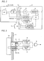
- Fig. 2 shows an overall structure of the electronic endoscope apparatus.
- a connector 14a of a scope 10A of type A is connected to a connector receiver 14b of a processor unit (an apparatus body) 12, and this processor unit 12 is provided with a connector receiver 15b for connecting another scope of type B.
- the scope 10A contains therein a CCD 17 which is a solid body photographing element, a CDS (correlation double sampling) /AGC (auto gain control) circuit 18 for inputting an image taking signal which has been obtained by this CCD 17, and so on.
- a CCD 17 which is a solid body photographing element
- CDS correlation double sampling
- AGC auto gain control
- the processor unit 12 contains therein a CCD driving pulse circuit 20 for driving the CCD 17, a scope power supplying circuit 21 for supplying necessary power to the scope 10A, an A/D converter 22 for inputting an output of the CDS/AGC circuit 18, an image processing circuit 23 which performs a determined image processing of the output signal of this A/D converter 22, and a CPU (or a microcomputer) 24 which totally controls these circuits and also controls insertion and extraction of the cap.
- a CCD driving pulse circuit 20 for driving the CCD 17
- a scope power supplying circuit 21 for supplying necessary power to the scope 10A
- an A/D converter 22 for inputting an output of the CDS/AGC circuit 18
- an image processing circuit 23 which performs a determined image processing of the output signal of this A/D converter 22
- a CPU or a microcomputer
- a cap (in a round shape, for example) 15c which is mounted and connected to the aforesaid connector receiver 15b (as for the other connector receiver 14b, a cap in a square shape for example is provided), and at the same time, a cap insertion and extraction detecting circuit 26 is connected to the connector receivers 14b, 15b.
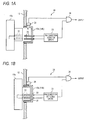
- a structure related to the cap 15c, the connector receiver 15b and the cap insertion and extraction detecting circuit 26 is shown in Figs. 1A and 1B .
- a photo-interrupter (an insertion detecting circuit) 28 for detecting an inserted state of the cap 15c is provided on a side face of the connector receiver 15b.
- This photo-interrupter 28 has a light emitting part (such as a light emitting diode) and a light receiving part (a photo-transistor), and can detect the inserted state of the cap 15c with respect to the connector receiver 15b, by reflecting a light emitted from the light emitting part from the side face of the cap 15c, and by detecting the reflected light in the light receiving part.
- a plurality of pins (electrodes) 30 are arranged in the connector receiver 15b, while two pin receivers (electrodes) 31 are provided in the cap 15c (arrangement of these pins and pin receivers may be reversed or some other structures may be employed). These pin receivers 31 make short circuits inside.
- the connector receiver 15b is provided with a pin connection detecting circuit 33 for detecting connection between the pins 30 and the pin receivers 31, and an AND circuit 34 is provided on an after stage of the pin connection detecting circuit 33 and the aforesaid photo-interrupter 28.
- the cap insertion and extraction detecting circuit 26 in this embodiment when the cap 15c is mounted to the connector receiver 15b, as shown in Fig. 1B from the state as shown in Fig. 1A , the insertion of the cap 15c itself is detected by the photo-interrupter 28, and the connection between the pins 30 and the pin receivers 31 is also detected by the pin connection detecting circuit 33. At this moment only, a signal (High signal) for judging that the cap 15c has been mounted (mounting of the cap) is issued.
- This embodiment has the above described structure, and the electronic endoscope apparatus in this embodiment is so constructed that a plurality of the scopes 10A or the like can be connected to the processor unit 12, as described referring to Figs. 5A and 5B .
- the connector 14a of the scope 10A is connected to the connector receiver 14b of the processor unit 12, as shown in Fig. 2
- the cap 15c is mounted to the other connector receiver 15b.
- operation as shown in Fig. 4 is performed in this embodiment.
- step 101 when the mounting of the cap 15c has been performed as described above, it is judged in step 101 whether or not the cap insertion and extraction detecting circuit 26 has detected the insertion of the cap 15c. Then, as described referring to Fig. 1B , when the insertion of the cap 15c has been detected by the photo-interrupter 28, and the connection between the pins (30, 31) has been detected by the pin connection detecting circuit 33, it is judged that the cap 15c has been mounted (YES). Then, in step 102, the CPU 24 energizes the CCD driving pulse circuit 20 and the scope power supplying circuit 21, whereby supply of CCD driving pulse and supply of scope power to the CCD 17 of the scope 10A is started (step 103).
- step 104 the CPU 24 requests to display an image observed by the scope, and a determined signal processing is performed on an image signal which has been inputted from the scope 10A, in the image processing circuit 23, and the observed image is displayed on a monitor (step 105).
- the CPU 24 stops the CCD driving pulse circuit 20 and the scope power supplying circuit 21 in step 106, and therefore, supply of the CCD driving pulse to the CCD 17 and supply of the scope power is stopped (107). Then, in step 108, the CPU 24 requests a message that the cap 15c should not be extracted, and the massage to the effect that the cap 15c should not be extracted is displayed on the monitor or the like (step 109).
- Fig. 3 shows another example of the structure of the insertion detecting circuit in the cap insertion and extraction detecting circuit 26.
- the insertion detecting circuit in this example there are provided an operating rod 36 which is supported so as to reciprocally move to the right and left in the drawing, a micro switch 37 arranged at a back end side of this operating rod 36, and a switch on/off detecting circuit 38 for detecting of/off of the micro switch 37.
- the insertion detecting circuit in this structure when the operating rod 36 is pushed by the insertion of the cap 15c, the micro switch 37 is turned on, whereby the insertion of the cap 15c is detected. Therefore, in the cap insertion and extraction detecting circuit 26, only when turning on of the micro switch 37 has been detected by this switch on/off detecting circuit 38, and the connection of the pins has been detected by the pin connection detecting circuit 33, an output of the AND circuit 34 becomes high. As the results, it is judged that the cap 15c has been mounted.
- the invention is applied to the electronic endoscope apparatus in the embodiment, it is also possible to apply the invention to a complex observation apparatus in which a scope is connected to an ultrasonic probe, for example.
Landscapes
- Health & Medical Sciences (AREA)
- Life Sciences & Earth Sciences (AREA)
- Surgery (AREA)
- Biomedical Technology (AREA)
- Medical Informatics (AREA)
- Optics & Photonics (AREA)
- Pathology (AREA)
- Radiology & Medical Imaging (AREA)
- Biophysics (AREA)
- Engineering & Computer Science (AREA)
- Physics & Mathematics (AREA)
- Heart & Thoracic Surgery (AREA)
- Nuclear Medicine, Radiotherapy & Molecular Imaging (AREA)
- Molecular Biology (AREA)
- Animal Behavior & Ethology (AREA)
- General Health & Medical Sciences (AREA)
- Public Health (AREA)
- Veterinary Medicine (AREA)
- Endoscopes (AREA)
- Instruments For Viewing The Inside Of Hollow Bodies (AREA)
- Apparatus For Radiation Diagnosis (AREA)
- Magnetic Resonance Imaging Apparatus (AREA)
- Accessory Devices And Overall Control Thereof (AREA)
Abstract
Description
- The present invention relates to an observed image forming apparatus, and more particularly, to a structure of an electronic endoscope apparatus or a complex observation apparatus provided with a plurality of connector receivers for connecting a plurality of observation devices by way of connectors, wherein a cap is mounted to the connector receiver to which the observation device is not connected.
- The electronic endoscope apparatus can display an image of an object to be observed on a monitor, by taking an image of the object to be observed by a CCD (Charge Coupled Device) which is a solid body photographing element mounted on a scope (an electronic endoscope) for example, by supplying an image taking signal from this CCD to a processor unit, and by performing a determined process on the signal in an image processing circuit in this processor unit. The electronic endoscope apparatus of this type is so constructed that a plurality of scopes having different types of the CCD and different image taking systems can be connected to the processor unit. There is also a complex observation apparatus which is so constructed that as well as the aforesaid scopes, ultrasonic probes for taking ultrasonic images can be connected thereto. With this complex observation apparatus, it is possible to display and observe both an electronic endoscope image and an ultrasonic image.
- In
Figs. 5A and 5B , there is shown a structure of the related-art electronic endoscope. As shown inFig. 5A , in anelectronic endoscope 1A of type A, for example, anoptical connector 3 and anelectric connector 4a in a square shape are connected to aprocessor unit 2. With thisoptical connector 3, a light guide for supplying light of a light source into theelectronic endoscope 1A, as an illumination light is connected to theprocessor unit 2. Theelectric connector 4a is provided for the purpose of connecting a signal line for mainly transmitting an image signal and so on which has been obtained by the CCD or the like mounted on theelectronic endoscope 1A, to theprocessor unit 2. - Moreover, as shown in
Fig. 5B , in anelectronic endoscope 1B of type B, for example, theoptical connector 3 and anelectric connector 5a in a round shape are connected to theprocessor unit 2. On the other hand, theprocessor unit 2 is provided with aconnector receiver 4b in a square shape which is fit for theelectric connector 4a in a square shape of theelectronic endoscope 1A of type A, and aconnector receiver 5b in a round shape which is fit for theelectric connector 5a in a round shape of theelectronic endoscope 1B of type B. In other words, in the related-art case, the twoconnector receivers electronic endoscopes electric connectors electronic endoscopes - By the way, in the related-art electronic endoscope apparatus, in case where the connector is connected to one of the
connector receivers Figs. 5A and 5B , water content may intrude into theconnector receiver processor unit 2, in some cases. Moreover, such possibility that a user of the like may get in touch with electrodes such as pins inside theconnector receivers - Under the circumstances,
caps connector receivers Figs. 5A and 5B . Specifically, thecaps processor unit 2 by means of acoupling cord 6, so that thecaps connector receivers - However, in this manner of simply mounting the
caps connector receivers caps caps connector receivers - The invention has been made in view of the above described problems, and it is an object of the invention to provide an electronic endoscope apparatus in which electrical safety of an internal circuit can be secured, and such possibility that a user may get in touch with an electrode in a connector receiver can be eliminated, even in case where a cap is forgotten to be mounted to the connector receiver or incompletely mounted.
- In order to attain the above described object, according to a first aspect of the invention, there is provided an observed image forming apparatus comprising: an apparatus body including a plurality of connector receivers to which electric connectors of a plurality of observation devices for obtaining an image of an object to be observed can be connected; a cap that is to be mounted to one of said plurality of connector receivers to which any of said plurality of electric connectors is not connected; and a cap insertion and extraction detecting circuit that detects whether or not the cap is mounted to the one of the connector receivers in the apparatus body, wherein, when mounting of the cap has been detected by the cap insertion and extraction detecting circuit, one of the observation devices an electric connector of which is connected to the other one of the connector receivers in the apparatus body is controlled to be driven.
- According to second aspect of the invention, there is provided the observed image forming apparatus, wherein the cap insertion and extraction detecting circuit comprises: an insertion detecting circuit that detects insertion of the cap; and a pin connection detecting circuit that detects pin connection between the cap and the one of the connector receivers, and wherein the mounting of the cap is judged when the insertion of the cap has been detected by the insertion detecting circuit, and the pin connection has been detected by the pin connection detecting circuit.
- According to the first aspect of the invention, only when the mounting of the cap has been detected by the cap insertion and extraction detecting circuit, power is supplied to the observation device such as the scope (electronic endoscope) and the ultrasonic probe, for example, and the obtained image is displayed on a monitor or the like. In short, unless the cap is mounted, the image will not be displayed.
- According to the second aspect of the invention, only when the insertion of the cap has been detected by the insertion detecting circuit such as a photo-interrupter, and the pin connection between the cap (the cap provided with a short-circuited electrode) and the connector receiver has been detected by the pin connection detecting circuit,the observation deviceisdriven. Inthismanner, the mounting of the cap can be confirmed through double detection.
-
-
Figs. 1A and 1B show a structure related to insertion and extraction of a cap to and from a connector receiver of an electronic endoscope apparatus which is an observed image forming apparatus in an embodiment according to the invention, in whichFig. 1A is a view showing a state before the cap is mounted, andFig. 1B is a view showing a state after the cap has been mounted; -
Fig. 2 is a block diagram showing an overall structure of the electronic endoscope apparatus in the embodiment; -
Fig. 3 is a view showing another example of a structure of an insertion detecting circuit in the embodiment; -
Fig. 4 is a flow chart showing operation related to mounting/non-mounting of the cap in the electronic endoscope in the embodiment; and -
Figs. 5A and 5B show structures of the related-art electronic endoscopes, in whichFig. 5A is a perspective view in case where a scope of type A is used, andFig. 5B is a perspective view in case where a scope of type B is used. -
Figs. 1A, 1B and2 show a structure of an electronic endoscope apparatus which is an observed image forming apparatus in an embodiment according to the invention.Figs. 1A and 1B show a structure related to insertion and extraction of a cap into and from a connector receiver of a processor unit, andFig. 2 shows an overall structure of the electronic endoscope apparatus. In the beginning, as shown inFig. 2 , in the electronic endoscope apparatus, aconnector 14a of ascope 10A of type A (an observation device-an electronic endoscope) is connected to aconnector receiver 14b of a processor unit (an apparatus body) 12, and thisprocessor unit 12 is provided with aconnector receiver 15b for connecting another scope of type B. Thescope 10A contains therein aCCD 17 which is a solid body photographing element, a CDS (correlation double sampling) /AGC (auto gain control)circuit 18 for inputting an image taking signal which has been obtained by thisCCD 17, and so on. - On the other hand, the
processor unit 12 contains therein a CCDdriving pulse circuit 20 for driving theCCD 17, a scopepower supplying circuit 21 for supplying necessary power to thescope 10A, an A/D converter 22 for inputting an output of the CDS/AGC circuit 18, animage processing circuit 23 which performs a determined image processing of the output signal of this A/D converter 22, and a CPU (or a microcomputer) 24 which totally controls these circuits and also controls insertion and extraction of the cap. - In this embodiment, there is provided a cap (in a round shape, for example) 15c which is mounted and connected to the
aforesaid connector receiver 15b (as for theother connector receiver 14b, a cap in a square shape for example is provided), and at the same time, a cap insertion andextraction detecting circuit 26 is connected to theconnector receivers - A structure related to the
cap 15c, theconnector receiver 15b and the cap insertion andextraction detecting circuit 26 is shown inFigs. 1A and 1B . A photo-interrupter (an insertion detecting circuit) 28 for detecting an inserted state of thecap 15c is provided on a side face of theconnector receiver 15b. This photo-interrupter 28 has a light emitting part (such as a light emitting diode) and a light receiving part (a photo-transistor), and can detect the inserted state of thecap 15c with respect to theconnector receiver 15b, by reflecting a light emitted from the light emitting part from the side face of thecap 15c, and by detecting the reflected light in the light receiving part. - A plurality of pins (electrodes) 30 are arranged in the
connector receiver 15b, while two pin receivers (electrodes) 31 are provided in thecap 15c (arrangement of these pins and pin receivers may be reversed or some other structures may be employed). Thesepin receivers 31 make short circuits inside. Moreover, theconnector receiver 15b is provided with a pinconnection detecting circuit 33 for detecting connection between thepins 30 and thepin receivers 31, and anAND circuit 34 is provided on an after stage of the pinconnection detecting circuit 33 and the aforesaid photo-interrupter 28. - Specifically, in the cap insertion and
extraction detecting circuit 26 in this embodiment, when thecap 15c is mounted to theconnector receiver 15b, as shown inFig. 1B from the state as shown inFig. 1A , the insertion of thecap 15c itself is detected by the photo-interrupter 28, and the connection between thepins 30 and thepin receivers 31 is also detected by the pinconnection detecting circuit 33. At this moment only, a signal (High signal) for judging that thecap 15c has been mounted (mounting of the cap) is issued. - This embodiment has the above described structure, and the electronic endoscope apparatus in this embodiment is so constructed that a plurality of the
scopes 10A or the like can be connected to theprocessor unit 12, as described referring toFigs. 5A and 5B . For example, in case where theconnector 14a of thescope 10A is connected to theconnector receiver 14b of theprocessor unit 12, as shown inFig. 2 , thecap 15c is mounted to theother connector receiver 15b. On this occasion, operation as shown inFig. 4 is performed in this embodiment. - In
Fig. 4 , when the mounting of thecap 15c has been performed as described above, it is judged instep 101 whether or not the cap insertion andextraction detecting circuit 26 has detected the insertion of thecap 15c. Then, as described referring toFig. 1B , when the insertion of thecap 15c has been detected by the photo-interrupter 28, and the connection between the pins (30, 31) has been detected by the pinconnection detecting circuit 33, it is judged that thecap 15c has been mounted (YES). Then, instep 102, theCPU 24 energizes the CCD drivingpulse circuit 20 and the scopepower supplying circuit 21, whereby supply of CCD driving pulse and supply of scope power to theCCD 17 of thescope 10A is started (step 103). Then, instep 104, theCPU 24 requests to display an image observed by the scope, and a determined signal processing is performed on an image signal which has been inputted from thescope 10A, in theimage processing circuit 23, and the observed image is displayed on a monitor (step 105). - On the other hand, in case where the
cap 15c is not yet mounted, has been detached or has been extracted, as shown inFig. 1A , the insertion of thecap 15c is not detected by the photo-interrupter 28 (non-insertion is detected), the connection of the pins is not detected by the pin connection detecting circuit 33 (non-connection is detected) or both are not detected in theaforesaid step 101, and it is judged that thecap 15c is not mounted (NO). In this case, theCPU 24 stops the CCD drivingpulse circuit 20 and the scopepower supplying circuit 21 instep 106, and therefore, supply of the CCD driving pulse to theCCD 17 and supply of the scope power is stopped (107). Then, instep 108, theCPU 24 requests a message that thecap 15c should not be extracted, and the massage to the effect that thecap 15c should not be extracted is displayed on the monitor or the like (step 109). - In the above described cap insertion and
extraction detecting circuit 26, only when the insertion of thecap 15c itself has been detected by the photo-interrupter 28 and the connection of thepin receivers 31 of thecap 15c to thepins 30 of theconnector receiver 15b has been detected by the pinconnection detecting circuit 33, thescope 10A is driven to operate. Therefore, through this double detection, forgetting to mount thecap 15c and incompletely mounting can be reliably prevented. -
Fig. 3 shows another example of the structure of the insertion detecting circuit in the cap insertion andextraction detecting circuit 26. In the insertion detecting circuit in this example, there are provided anoperating rod 36 which is supported so as to reciprocally move to the right and left in the drawing, amicro switch 37 arranged at a back end side of this operatingrod 36, and a switch on/off detectingcircuit 38 for detecting of/off of themicro switch 37. - With the insertion detecting circuit in this structure, when the operating
rod 36 is pushed by the insertion of thecap 15c, themicro switch 37 is turned on, whereby the insertion of thecap 15c is detected. Therefore, in the cap insertion andextraction detecting circuit 26, only when turning on of themicro switch 37 has been detected by this switch on/off detectingcircuit 38, and the connection of the pins has been detected by the pinconnection detecting circuit 33, an output of the ANDcircuit 34 becomes high. As the results, it is judged that thecap 15c has been mounted. - Although in the above described embodiment, it is so adapted that operation of the
scope 10A starts, when the mounting of thecap 15c has been detected by the cap insertion andextraction detecting circuit 26, it is also possible to start operation of theprocessor unit 12 including thescope 10A, that is, operation of the electronic endoscope apparatus. - Moreover, although the invention is applied to the electronic endoscope apparatus in the embodiment, it is also possible to apply the invention to a complex observation apparatus in which a scope is connected to an ultrasonic probe, for example.
- According to the observed image forming apparatus of the invention, there is obtained such advantage that electrical safety of the internal circuit can be secured, even in case where the cap is forgotten to be mounted, or incompletely mounted, and such possibility that a user may get in touch with the electrode inside the connector receiver can be eliminated.
- Moreover, according to the second aspect of the invention, forgetting to mount the cap and incomplete mounting of the cap can be reliably prevented through the double detection.
- The entire disclosure of each and every foreign patent application from which the benefit of foreign priority has been claimed in the present application is incorporated herein by reference, as if fully set forth.
Claims (2)
- An observed image forming apparatus comprising:an apparatus body including a plurality of connector receivers to which electric connectors of a plurality of observation devices for obtaining an image of an object to be observed can be connected;a cap that is to be mounted to one of said plurality of connector receivers to which any of said plurality of electric connectors is not connected; anda cap insertion and extraction detecting circuit that detects whether or not the cap is mounted to the one of the connector receivers in the apparatus body,wherein, when mounting of the cap has been detected by the cap insertion and extraction detecting circuit, one of the observation devices an electric connector of which is connected to the other one of the connector receivers in the apparatus body is controlled to be driven.
- An observed image forming apparatus as claimed in claim 1,
wherein the cap insertion and extraction detecting circuit comprises: an insertion detecting circuit that detects insertion of the cap; and a pin connection detecting circuit that detects pin connection between the cap and the one of the connector receivers, and
wherein the mounting of the cap is judged when the insertion of the cap has been detected by the insertion detecting circuit, and the pin connection has been detected by the pin connection detecting circuit.
Applications Claiming Priority (1)
| Application Number | Priority Date | Filing Date | Title |
|---|---|---|---|
| JP2007241763A JP4904470B2 (en) | 2007-09-19 | 2007-09-19 | Observation image forming apparatus |
Publications (2)
| Publication Number | Publication Date |
|---|---|
| EP2039283A1 true EP2039283A1 (en) | 2009-03-25 |
| EP2039283B1 EP2039283B1 (en) | 2010-02-24 |
Family
ID=40053770
Family Applications (1)
| Application Number | Title | Priority Date | Filing Date |
|---|---|---|---|
| EP08015307A Not-in-force EP2039283B1 (en) | 2007-09-19 | 2008-08-29 | Observed image forming apparatus |
Country Status (6)
| Country | Link |
|---|---|
| US (1) | US8376935B2 (en) |
| EP (1) | EP2039283B1 (en) |
| JP (1) | JP4904470B2 (en) |
| CN (1) | CN101390745B (en) |
| AT (1) | ATE458438T1 (en) |
| DE (1) | DE602008000705D1 (en) |
Families Citing this family (33)
| Publication number | Priority date | Publication date | Assignee | Title |
|---|---|---|---|---|
| US10524645B2 (en) | 2009-06-18 | 2020-01-07 | Endochoice, Inc. | Method and system for eliminating image motion blur in a multiple viewing elements endoscope |
| US9474440B2 (en) | 2009-06-18 | 2016-10-25 | Endochoice, Inc. | Endoscope tip position visual indicator and heat management system |
| US11103213B2 (en) | 2009-10-08 | 2021-08-31 | C. R. Bard, Inc. | Spacers for use with an ultrasound probe |
| CA2806353A1 (en) | 2010-08-09 | 2012-02-16 | C.R. Bard Inc. | Support and cover structures for an ultrasound probe head |
| US9706908B2 (en) | 2010-10-28 | 2017-07-18 | Endochoice, Inc. | Image capture and video processing systems and methods for multiple viewing element endoscopes |
| US10663714B2 (en) | 2010-10-28 | 2020-05-26 | Endochoice, Inc. | Optical system for an endoscope |
| US10517464B2 (en) | 2011-02-07 | 2019-12-31 | Endochoice, Inc. | Multi-element cover for a multi-camera endoscope |
| USD699359S1 (en) | 2011-08-09 | 2014-02-11 | C. R. Bard, Inc. | Ultrasound probe head |
| USD724745S1 (en) | 2011-08-09 | 2015-03-17 | C. R. Bard, Inc. | Cap for an ultrasound probe |
| WO2013070775A1 (en) | 2011-11-07 | 2013-05-16 | C.R. Bard, Inc | Ruggedized ultrasound hydrogel insert |
| EP2861153A4 (en) * | 2012-06-15 | 2016-10-19 | Bard Inc C R | Apparatus and methods for detection of a removable cap on an ultrasound probe |
| US12207796B2 (en) | 2013-03-28 | 2025-01-28 | Endochoice Inc. | Multi-jet controller for an endoscope |
| US10595714B2 (en) | 2013-03-28 | 2020-03-24 | Endochoice, Inc. | Multi-jet controller for an endoscope |
| US9636003B2 (en) | 2013-06-28 | 2017-05-02 | Endochoice, Inc. | Multi-jet distributor for an endoscope |
| JP6669647B2 (en) | 2013-05-07 | 2020-03-18 | エンドチョイス インコーポレイテッドEndochoice, Inc. | White balance correction device for use with endoscope and method of performing white balance correction |
| US10064541B2 (en) * | 2013-08-12 | 2018-09-04 | Endochoice, Inc. | Endoscope connector cover detection and warning system |
| US9943218B2 (en) | 2013-10-01 | 2018-04-17 | Endochoice, Inc. | Endoscope having a supply cable attached thereto |
| US9968242B2 (en) | 2013-12-18 | 2018-05-15 | Endochoice, Inc. | Suction control unit for an endoscope having two working channels |
| WO2015112747A2 (en) | 2014-01-22 | 2015-07-30 | Endochoice, Inc. | Image capture and video processing systems and methods for multiple viewing element endoscopes |
| CN106659368B (en) | 2014-07-21 | 2020-04-17 | 恩多巧爱思股份有限公司 | Multi-focus and multi-camera endoscope system |
| WO2016033403A1 (en) | 2014-08-29 | 2016-03-03 | Endochoice, Inc. | Systems and methods for varying stiffness of an endoscopic insertion tube |
| JP6401013B2 (en) * | 2014-10-29 | 2018-10-03 | オリンパス株式会社 | Endoscope system |
| WO2016100173A1 (en) | 2014-12-18 | 2016-06-23 | Endochoice, Inc. | System and method for processing video images generated by a multiple viewing elements endoscope |
| US10376181B2 (en) | 2015-02-17 | 2019-08-13 | Endochoice, Inc. | System for detecting the location of an endoscopic device during a medical procedure |
| US12529882B2 (en) | 2015-02-24 | 2026-01-20 | Endochoice, Inc. | Optical system for an endoscope |
| US10078207B2 (en) | 2015-03-18 | 2018-09-18 | Endochoice, Inc. | Systems and methods for image magnification using relative movement between an image sensor and a lens assembly |
| US10401611B2 (en) | 2015-04-27 | 2019-09-03 | Endochoice, Inc. | Endoscope with integrated measurement of distance to objects of interest |
| EP3367950A4 (en) | 2015-10-28 | 2019-10-02 | Endochoice, Inc. | DEVICE AND METHOD FOR FOLLOWING THE POSITION OF AN ENDOSCOPE IN THE BODY OF A PATIENT |
| JP6995749B2 (en) | 2015-11-24 | 2022-01-17 | エンドチョイス インコーポレイテッド | Disposable air / water valve for endoscopes |
| US10488648B2 (en) | 2016-02-24 | 2019-11-26 | Endochoice, Inc. | Circuit board assembly for a multiple viewing element endoscope using CMOS sensors |
| US10292570B2 (en) | 2016-03-14 | 2019-05-21 | Endochoice, Inc. | System and method for guiding and tracking a region of interest using an endoscope |
| JP7000353B2 (en) | 2016-06-21 | 2022-01-19 | エンドチョイス インコーポレイテッド | Endoscope system with multiple connection interfaces to interface with different video data signal sources |
| WO2021166184A1 (en) | 2020-02-20 | 2021-08-26 | リバーフィールド株式会社 | Surgical instrument holding device and surgery assisting device |
Citations (6)
| Publication number | Priority date | Publication date | Assignee | Title |
|---|---|---|---|---|
| EP0061748A1 (en) * | 1981-04-01 | 1982-10-06 | Olympus Optical Co., Ltd. | Light supply apparatus for endoscope |
| US4853774A (en) * | 1988-10-28 | 1989-08-01 | Welch Allyn, Inc. | Auxiliary light apparatus for borescope |
| US4860094A (en) * | 1987-03-10 | 1989-08-22 | Olympus Optical Co., Ltd. | Control apparatus for use with different types of endoscopes |
| JPH02271823A (en) * | 1989-04-13 | 1990-11-06 | Toshiba Corp | Electronic endoscope device |
| US5554893A (en) * | 1994-02-17 | 1996-09-10 | Machida Endoscope Co., Ltd. | System for controlling semiconductor |
| EP1600101A2 (en) * | 2004-05-25 | 2005-11-30 | Fujinon Corporation | Endoscope connector device, endoscope cable lead-out unit and endoscope device |
Family Cites Families (14)
| Publication number | Priority date | Publication date | Assignee | Title |
|---|---|---|---|---|
| JPS5764036A (en) * | 1980-10-08 | 1982-04-17 | Olympus Optical Co | Endoscope apparatus |
| US4855819A (en) * | 1987-01-31 | 1989-08-08 | Olympus Optical Co., Ltd. | Endoscope imaging system for use with multiple color imaging systems |
| JP3315180B2 (en) * | 1993-02-26 | 2002-08-19 | オリンパス光学工業株式会社 | Endoscope control device |
| JP3325098B2 (en) * | 1993-11-08 | 2002-09-17 | オリンパス光学工業株式会社 | Induction cautery equipment |
| JPH09253037A (en) * | 1996-03-21 | 1997-09-30 | Asahi Optical Co Ltd | Electronic endoscope device |
| JPH09308606A (en) * | 1996-05-23 | 1997-12-02 | Asahi Optical Co Ltd | Video processor for electronic endoscope |
| JP3956378B2 (en) * | 1997-06-30 | 2007-08-08 | フジノン株式会社 | Endoscope cleaning device |
| US6327493B1 (en) * | 1997-08-28 | 2001-12-04 | Olympus Optical Co., Ltd. | Light scanning devices of a water-tight structure to be inserted into a body cavity to obtain optical information on inside of a biological tissue |
| EP1529495B1 (en) * | 2002-06-18 | 2016-10-05 | Olympus Corporation | Resectoscope |
| JP2004236738A (en) | 2003-02-04 | 2004-08-26 | Fuji Photo Optical Co Ltd | Processor for electronic endoscope |
| AU2004257531B2 (en) * | 2003-07-22 | 2007-11-08 | Olympus Corporation | High temperature and high pressure steam sterilization method for endoscope, and endoscope |
| US7766905B2 (en) * | 2004-02-12 | 2010-08-03 | Covidien Ag | Method and system for continuity testing of medical electrodes |
| JP4769861B2 (en) * | 2006-03-30 | 2011-09-07 | 富士通株式会社 | Electronic device, management method, and management program |
| JP4756070B2 (en) * | 2006-03-30 | 2011-08-24 | 富士通株式会社 | Information processing apparatus, management method, and management program |
-
2007
- 2007-09-19 JP JP2007241763A patent/JP4904470B2/en not_active Expired - Fee Related
-
2008
- 2008-08-28 US US12/200,493 patent/US8376935B2/en not_active Expired - Fee Related
- 2008-08-29 CN CN200810214954.7A patent/CN101390745B/en not_active Expired - Fee Related
- 2008-08-29 EP EP08015307A patent/EP2039283B1/en not_active Not-in-force
- 2008-08-29 AT AT08015307T patent/ATE458438T1/en not_active IP Right Cessation
- 2008-08-29 DE DE602008000705T patent/DE602008000705D1/en active Active
Patent Citations (6)
| Publication number | Priority date | Publication date | Assignee | Title |
|---|---|---|---|---|
| EP0061748A1 (en) * | 1981-04-01 | 1982-10-06 | Olympus Optical Co., Ltd. | Light supply apparatus for endoscope |
| US4860094A (en) * | 1987-03-10 | 1989-08-22 | Olympus Optical Co., Ltd. | Control apparatus for use with different types of endoscopes |
| US4853774A (en) * | 1988-10-28 | 1989-08-01 | Welch Allyn, Inc. | Auxiliary light apparatus for borescope |
| JPH02271823A (en) * | 1989-04-13 | 1990-11-06 | Toshiba Corp | Electronic endoscope device |
| US5554893A (en) * | 1994-02-17 | 1996-09-10 | Machida Endoscope Co., Ltd. | System for controlling semiconductor |
| EP1600101A2 (en) * | 2004-05-25 | 2005-11-30 | Fujinon Corporation | Endoscope connector device, endoscope cable lead-out unit and endoscope device |
Also Published As
| Publication number | Publication date |
|---|---|
| JP4904470B2 (en) | 2012-03-28 |
| US20090076327A1 (en) | 2009-03-19 |
| JP2009072247A (en) | 2009-04-09 |
| DE602008000705D1 (en) | 2010-04-08 |
| EP2039283B1 (en) | 2010-02-24 |
| ATE458438T1 (en) | 2010-03-15 |
| US8376935B2 (en) | 2013-02-19 |
| CN101390745A (en) | 2009-03-25 |
| CN101390745B (en) | 2010-12-08 |
Similar Documents
| Publication | Publication Date | Title |
|---|---|---|
| EP2039283B1 (en) | Observed image forming apparatus | |
| EP2090216B1 (en) | Processor for endoscope and endoscope system | |
| US12102284B2 (en) | Endoscope apparatus, method of controlling endoscope apparatus and non-transitory computer readable recording medium recording program for controlling endoscope apparatus | |
| JP5226354B2 (en) | Wireless imaging system and imaging apparatus | |
| CN104349704B (en) | Endoscope | |
| US8294756B2 (en) | Image pickup system and method for maintaining the same | |
| CN113271837B (en) | Endoscope front end structure and endoscope | |
| US11179026B2 (en) | Endoscope processor, endoscope and endoscope system | |
| US20080027284A1 (en) | Endoscope Having Power Shutdown Unit | |
| US12011145B2 (en) | Endoscope distal end structure and endoscope | |
| US10098522B2 (en) | Endoscope | |
| US12070191B2 (en) | Holding frame, endoscope distal end structure, and endoscope | |
| JPH11169341A (en) | Connection device between endoscope and light source device | |
| EP2805668B1 (en) | Imaging unit and imaging system | |
| JP2009201543A (en) | Endoscope system | |
| JP4918599B2 (en) | Endoscopic observation method | |
| JP6122802B2 (en) | Endoscope system and endoscope | |
| CN219374586U (en) | Detection apparatus for endoscope image processing system | |
| JP4648718B2 (en) | CCD damage prevention system | |
| JP4477168B2 (en) | Electronic endoscope | |
| JP2019076655A (en) | Processor for endoscope and endoscope system | |
| JP6994312B2 (en) | Board support structure for electronic devices | |
| KR20160088739A (en) | Camera endoscope with optical communicator | |
| JP2019130049A (en) | Electronic endoscope system, processor, and control method | |
| CN111491548A (en) | Inspection device for endoscope and inspection system for endoscope |
Legal Events
| Date | Code | Title | Description |
|---|---|---|---|
| PUAI | Public reference made under article 153(3) epc to a published international application that has entered the european phase |
Free format text: ORIGINAL CODE: 0009012 |
|
| 17P | Request for examination filed |
Effective date: 20080829 |
|
| AK | Designated contracting states |
Kind code of ref document: A1 Designated state(s): AT BE BG CH CY CZ DE DK EE ES FI FR GB GR HR HU IE IS IT LI LT LU LV MC MT NL NO PL PT RO SE SI SK TR |
|
| AX | Request for extension of the european patent |
Extension state: AL BA MK RS |
|
| GRAP | Despatch of communication of intention to grant a patent |
Free format text: ORIGINAL CODE: EPIDOSNIGR1 |
|
| GRAJ | Information related to disapproval of communication of intention to grant by the applicant or resumption of examination proceedings by the epo deleted |
Free format text: ORIGINAL CODE: EPIDOSDIGR1 |
|
| GRAP | Despatch of communication of intention to grant a patent |
Free format text: ORIGINAL CODE: EPIDOSNIGR1 |
|
| AKX | Designation fees paid |
Designated state(s): AT BE BG CH CY CZ DE DK EE ES FI FR GB GR HR HU IE IS IT LI LT LU LV MC MT NL NO PL PT RO SE SI SK TR |
|
| GRAS | Grant fee paid |
Free format text: ORIGINAL CODE: EPIDOSNIGR3 |
|
| GRAA | (expected) grant |
Free format text: ORIGINAL CODE: 0009210 |
|
| AK | Designated contracting states |
Kind code of ref document: B1 Designated state(s): AT BE BG CH CY CZ DE DK EE ES FI FR GB GR HR HU IE IS IT LI LT LU LV MC MT NL NO PL PT RO SE SI SK TR |
|
| REG | Reference to a national code |
Ref country code: GB Ref legal event code: FG4D |
|
| REG | Reference to a national code |
Ref country code: CH Ref legal event code: EP |
|
| REG | Reference to a national code |
Ref country code: IE Ref legal event code: FG4D |
|
| REF | Corresponds to: |
Ref document number: 602008000705 Country of ref document: DE Date of ref document: 20100408 Kind code of ref document: P |
|
| REG | Reference to a national code |
Ref country code: NL Ref legal event code: T3 |
|
| RAP2 | Party data changed (patent owner data changed or rights of a patent transferred) |
Owner name: FUJIFILM CORPORATION |
|
| REG | Reference to a national code |
Ref country code: NL Ref legal event code: SD Effective date: 20100608 |
|
| LTIE | Lt: invalidation of european patent or patent extension |
Effective date: 20100224 |
|
| PG25 | Lapsed in a contracting state [announced via postgrant information from national office to epo] |
Ref country code: LT Free format text: LAPSE BECAUSE OF FAILURE TO SUBMIT A TRANSLATION OF THE DESCRIPTION OR TO PAY THE FEE WITHIN THE PRESCRIBED TIME-LIMIT Effective date: 20100224 Ref country code: IS Free format text: LAPSE BECAUSE OF FAILURE TO SUBMIT A TRANSLATION OF THE DESCRIPTION OR TO PAY THE FEE WITHIN THE PRESCRIBED TIME-LIMIT Effective date: 20100624 Ref country code: HR Free format text: LAPSE BECAUSE OF FAILURE TO SUBMIT A TRANSLATION OF THE DESCRIPTION OR TO PAY THE FEE WITHIN THE PRESCRIBED TIME-LIMIT Effective date: 20100224 Ref country code: NO Free format text: LAPSE BECAUSE OF FAILURE TO SUBMIT A TRANSLATION OF THE DESCRIPTION OR TO PAY THE FEE WITHIN THE PRESCRIBED TIME-LIMIT Effective date: 20100524 |
|
| REG | Reference to a national code |
Ref country code: GB Ref legal event code: 732E Free format text: REGISTERED BETWEEN 20100722 AND 20100728 |
|
| PG25 | Lapsed in a contracting state [announced via postgrant information from national office to epo] |
Ref country code: FI Free format text: LAPSE BECAUSE OF FAILURE TO SUBMIT A TRANSLATION OF THE DESCRIPTION OR TO PAY THE FEE WITHIN THE PRESCRIBED TIME-LIMIT Effective date: 20100224 Ref country code: AT Free format text: LAPSE BECAUSE OF FAILURE TO SUBMIT A TRANSLATION OF THE DESCRIPTION OR TO PAY THE FEE WITHIN THE PRESCRIBED TIME-LIMIT Effective date: 20100224 Ref country code: SI Free format text: LAPSE BECAUSE OF FAILURE TO SUBMIT A TRANSLATION OF THE DESCRIPTION OR TO PAY THE FEE WITHIN THE PRESCRIBED TIME-LIMIT Effective date: 20100224 Ref country code: PL Free format text: LAPSE BECAUSE OF FAILURE TO SUBMIT A TRANSLATION OF THE DESCRIPTION OR TO PAY THE FEE WITHIN THE PRESCRIBED TIME-LIMIT Effective date: 20100224 Ref country code: LV Free format text: LAPSE BECAUSE OF FAILURE TO SUBMIT A TRANSLATION OF THE DESCRIPTION OR TO PAY THE FEE WITHIN THE PRESCRIBED TIME-LIMIT Effective date: 20100224 |
|
| PG25 | Lapsed in a contracting state [announced via postgrant information from national office to epo] |
Ref country code: ES Free format text: LAPSE BECAUSE OF FAILURE TO SUBMIT A TRANSLATION OF THE DESCRIPTION OR TO PAY THE FEE WITHIN THE PRESCRIBED TIME-LIMIT Effective date: 20100604 Ref country code: RO Free format text: LAPSE BECAUSE OF FAILURE TO SUBMIT A TRANSLATION OF THE DESCRIPTION OR TO PAY THE FEE WITHIN THE PRESCRIBED TIME-LIMIT Effective date: 20100224 Ref country code: SE Free format text: LAPSE BECAUSE OF FAILURE TO SUBMIT A TRANSLATION OF THE DESCRIPTION OR TO PAY THE FEE WITHIN THE PRESCRIBED TIME-LIMIT Effective date: 20100224 Ref country code: GR Free format text: LAPSE BECAUSE OF FAILURE TO SUBMIT A TRANSLATION OF THE DESCRIPTION OR TO PAY THE FEE WITHIN THE PRESCRIBED TIME-LIMIT Effective date: 20100525 Ref country code: CY Free format text: LAPSE BECAUSE OF FAILURE TO SUBMIT A TRANSLATION OF THE DESCRIPTION OR TO PAY THE FEE WITHIN THE PRESCRIBED TIME-LIMIT Effective date: 20100224 Ref country code: BE Free format text: LAPSE BECAUSE OF FAILURE TO SUBMIT A TRANSLATION OF THE DESCRIPTION OR TO PAY THE FEE WITHIN THE PRESCRIBED TIME-LIMIT Effective date: 20100224 Ref country code: EE Free format text: LAPSE BECAUSE OF FAILURE TO SUBMIT A TRANSLATION OF THE DESCRIPTION OR TO PAY THE FEE WITHIN THE PRESCRIBED TIME-LIMIT Effective date: 20100224 |
|
| PG25 | Lapsed in a contracting state [announced via postgrant information from national office to epo] |
Ref country code: SK Free format text: LAPSE BECAUSE OF FAILURE TO SUBMIT A TRANSLATION OF THE DESCRIPTION OR TO PAY THE FEE WITHIN THE PRESCRIBED TIME-LIMIT Effective date: 20100224 Ref country code: BG Free format text: LAPSE BECAUSE OF FAILURE TO SUBMIT A TRANSLATION OF THE DESCRIPTION OR TO PAY THE FEE WITHIN THE PRESCRIBED TIME-LIMIT Effective date: 20100524 Ref country code: CZ Free format text: LAPSE BECAUSE OF FAILURE TO SUBMIT A TRANSLATION OF THE DESCRIPTION OR TO PAY THE FEE WITHIN THE PRESCRIBED TIME-LIMIT Effective date: 20100224 |
|
| PLBE | No opposition filed within time limit |
Free format text: ORIGINAL CODE: 0009261 |
|
| STAA | Information on the status of an ep patent application or granted ep patent |
Free format text: STATUS: NO OPPOSITION FILED WITHIN TIME LIMIT |
|
| PG25 | Lapsed in a contracting state [announced via postgrant information from national office to epo] |
Ref country code: DK Free format text: LAPSE BECAUSE OF FAILURE TO SUBMIT A TRANSLATION OF THE DESCRIPTION OR TO PAY THE FEE WITHIN THE PRESCRIBED TIME-LIMIT Effective date: 20100224 |
|
| 26N | No opposition filed |
Effective date: 20101125 |
|
| PG25 | Lapsed in a contracting state [announced via postgrant information from national office to epo] |
Ref country code: MC Free format text: LAPSE BECAUSE OF NON-PAYMENT OF DUE FEES Effective date: 20100831 |
|
| PG25 | Lapsed in a contracting state [announced via postgrant information from national office to epo] |
Ref country code: IE Free format text: LAPSE BECAUSE OF NON-PAYMENT OF DUE FEES Effective date: 20100829 |
|
| PG25 | Lapsed in a contracting state [announced via postgrant information from national office to epo] |
Ref country code: MT Free format text: LAPSE BECAUSE OF FAILURE TO SUBMIT A TRANSLATION OF THE DESCRIPTION OR TO PAY THE FEE WITHIN THE PRESCRIBED TIME-LIMIT Effective date: 20100224 |
|
| PG25 | Lapsed in a contracting state [announced via postgrant information from national office to epo] |
Ref country code: HU Free format text: LAPSE BECAUSE OF FAILURE TO SUBMIT A TRANSLATION OF THE DESCRIPTION OR TO PAY THE FEE WITHIN THE PRESCRIBED TIME-LIMIT Effective date: 20100825 Ref country code: LU Free format text: LAPSE BECAUSE OF NON-PAYMENT OF DUE FEES Effective date: 20100829 |
|
| PG25 | Lapsed in a contracting state [announced via postgrant information from national office to epo] |
Ref country code: TR Free format text: LAPSE BECAUSE OF FAILURE TO SUBMIT A TRANSLATION OF THE DESCRIPTION OR TO PAY THE FEE WITHIN THE PRESCRIBED TIME-LIMIT Effective date: 20100224 |
|
| REG | Reference to a national code |
Ref country code: CH Ref legal event code: PL |
|
| PG25 | Lapsed in a contracting state [announced via postgrant information from national office to epo] |
Ref country code: CH Free format text: LAPSE BECAUSE OF NON-PAYMENT OF DUE FEES Effective date: 20120831 Ref country code: LI Free format text: LAPSE BECAUSE OF NON-PAYMENT OF DUE FEES Effective date: 20120831 |
|
| PG25 | Lapsed in a contracting state [announced via postgrant information from national office to epo] |
Ref country code: PT Free format text: LAPSE BECAUSE OF NON-PAYMENT OF DUE FEES Effective date: 20100224 |
|
| PGFP | Annual fee paid to national office [announced via postgrant information from national office to epo] |
Ref country code: DE Payment date: 20140827 Year of fee payment: 7 Ref country code: NL Payment date: 20140710 Year of fee payment: 7 |
|
| PGFP | Annual fee paid to national office [announced via postgrant information from national office to epo] |
Ref country code: GB Payment date: 20140827 Year of fee payment: 7 |
|
| PGFP | Annual fee paid to national office [announced via postgrant information from national office to epo] |
Ref country code: IT Payment date: 20140821 Year of fee payment: 7 |
|
| REG | Reference to a national code |
Ref country code: FR Ref legal event code: PLFP Year of fee payment: 8 |
|
| PGFP | Annual fee paid to national office [announced via postgrant information from national office to epo] |
Ref country code: FR Payment date: 20150629 Year of fee payment: 8 |
|
| REG | Reference to a national code |
Ref country code: DE Ref legal event code: R119 Ref document number: 602008000705 Country of ref document: DE |
|
| GBPC | Gb: european patent ceased through non-payment of renewal fee |
Effective date: 20150829 |
|
| PG25 | Lapsed in a contracting state [announced via postgrant information from national office to epo] |
Ref country code: IT Free format text: LAPSE BECAUSE OF NON-PAYMENT OF DUE FEES Effective date: 20150829 |
|
| REG | Reference to a national code |
Ref country code: NL Ref legal event code: MM Effective date: 20150901 |
|
| PG25 | Lapsed in a contracting state [announced via postgrant information from national office to epo] |
Ref country code: NL Free format text: LAPSE BECAUSE OF NON-PAYMENT OF DUE FEES Effective date: 20150901 |
|
| PG25 | Lapsed in a contracting state [announced via postgrant information from national office to epo] |
Ref country code: DE Free format text: LAPSE BECAUSE OF NON-PAYMENT OF DUE FEES Effective date: 20160301 Ref country code: GB Free format text: LAPSE BECAUSE OF NON-PAYMENT OF DUE FEES Effective date: 20150829 |
|
| REG | Reference to a national code |
Ref country code: FR Ref legal event code: ST Effective date: 20170428 |
|
| PG25 | Lapsed in a contracting state [announced via postgrant information from national office to epo] |
Ref country code: FR Free format text: LAPSE BECAUSE OF NON-PAYMENT OF DUE FEES Effective date: 20160831 |