EP2038696B1 - Translating multifocal ophthalmic lenses - Google Patents
Translating multifocal ophthalmic lenses Download PDFInfo
- Publication number
- EP2038696B1 EP2038696B1 EP07799081.0A EP07799081A EP2038696B1 EP 2038696 B1 EP2038696 B1 EP 2038696B1 EP 07799081 A EP07799081 A EP 07799081A EP 2038696 B1 EP2038696 B1 EP 2038696B1
- Authority
- EP
- European Patent Office
- Prior art keywords
- zone
- vision zone
- distance
- lens
- near vision
- Prior art date
- Legal status (The legal status is an assumption and is not a legal conclusion. Google has not performed a legal analysis and makes no representation as to the accuracy of the status listed.)
- Active
Links
- 208000001491 myopia Diseases 0.000 claims description 55
- 210000001747 pupil Anatomy 0.000 description 34
- 230000003287 optical effect Effects 0.000 description 17
- 238000013461 design Methods 0.000 description 10
- 238000012937 correction Methods 0.000 description 7
- 239000000463 material Substances 0.000 description 5
- 238000013519 translation Methods 0.000 description 5
- 230000000052 comparative effect Effects 0.000 description 4
- 239000000017 hydrogel Substances 0.000 description 4
- 201000010041 presbyopia Diseases 0.000 description 4
- 230000006641 stabilisation Effects 0.000 description 4
- 238000011105 stabilization Methods 0.000 description 4
- 230000001419 dependent effect Effects 0.000 description 3
- 229920001296 polysiloxane Polymers 0.000 description 3
- -1 siloxane functionality Chemical group 0.000 description 3
- 238000000034 method Methods 0.000 description 2
- 239000011347 resin Substances 0.000 description 2
- 229920005989 resin Polymers 0.000 description 2
- 125000003178 carboxy group Chemical group [H]OC(*)=O 0.000 description 1
- 230000006835 compression Effects 0.000 description 1
- 238000007906 compression Methods 0.000 description 1
- 238000007796 conventional method Methods 0.000 description 1
- 238000007516 diamond turning Methods 0.000 description 1
- 235000013870 dimethyl polysiloxane Nutrition 0.000 description 1
- 239000004205 dimethyl polysiloxane Substances 0.000 description 1
- 230000000694 effects Effects 0.000 description 1
- 125000002887 hydroxy group Chemical group [H]O* 0.000 description 1
- 239000007788 liquid Substances 0.000 description 1
- 239000000203 mixture Substances 0.000 description 1
- 239000000178 monomer Substances 0.000 description 1
- 229920000435 poly(dimethylsiloxane) Polymers 0.000 description 1
- 229920002379 silicone rubber Polymers 0.000 description 1
- 230000008719 thickening Effects 0.000 description 1
Images


Classifications
-
- G—PHYSICS
- G02—OPTICS
- G02C—SPECTACLES; SUNGLASSES OR GOGGLES INSOFAR AS THEY HAVE THE SAME FEATURES AS SPECTACLES; CONTACT LENSES
- G02C7/00—Optical parts
- G02C7/02—Lenses; Lens systems ; Methods of designing lenses
- G02C7/04—Contact lenses for the eyes
-
- G—PHYSICS
- G02—OPTICS
- G02C—SPECTACLES; SUNGLASSES OR GOGGLES INSOFAR AS THEY HAVE THE SAME FEATURES AS SPECTACLES; CONTACT LENSES
- G02C7/00—Optical parts
- G02C7/02—Lenses; Lens systems ; Methods of designing lenses
- G02C7/04—Contact lenses for the eyes
- G02C7/041—Contact lenses for the eyes bifocal; multifocal
- G02C7/044—Annular configuration, e.g. pupil tuned
-
- A—HUMAN NECESSITIES
- A61—MEDICAL OR VETERINARY SCIENCE; HYGIENE
- A61F—FILTERS IMPLANTABLE INTO BLOOD VESSELS; PROSTHESES; DEVICES PROVIDING PATENCY TO, OR PREVENTING COLLAPSING OF, TUBULAR STRUCTURES OF THE BODY, e.g. STENTS; ORTHOPAEDIC, NURSING OR CONTRACEPTIVE DEVICES; FOMENTATION; TREATMENT OR PROTECTION OF EYES OR EARS; BANDAGES, DRESSINGS OR ABSORBENT PADS; FIRST-AID KITS
- A61F9/00—Methods or devices for treatment of the eyes; Devices for putting-in contact lenses; Devices to correct squinting; Apparatus to guide the blind; Protective devices for the eyes, carried on the body or in the hand
-
- G—PHYSICS
- G02—OPTICS
- G02C—SPECTACLES; SUNGLASSES OR GOGGLES INSOFAR AS THEY HAVE THE SAME FEATURES AS SPECTACLES; CONTACT LENSES
- G02C7/00—Optical parts
- G02C7/02—Lenses; Lens systems ; Methods of designing lenses
-
- G—PHYSICS
- G02—OPTICS
- G02C—SPECTACLES; SUNGLASSES OR GOGGLES INSOFAR AS THEY HAVE THE SAME FEATURES AS SPECTACLES; CONTACT LENSES
- G02C7/00—Optical parts
- G02C7/02—Lenses; Lens systems ; Methods of designing lenses
- G02C7/04—Contact lenses for the eyes
- G02C7/041—Contact lenses for the eyes bifocal; multifocal
- G02C7/043—Translating type
-
- G—PHYSICS
- G02—OPTICS
- G02C—SPECTACLES; SUNGLASSES OR GOGGLES INSOFAR AS THEY HAVE THE SAME FEATURES AS SPECTACLES; CONTACT LENSES
- G02C7/00—Optical parts
- G02C7/02—Lenses; Lens systems ; Methods of designing lenses
- G02C7/04—Contact lenses for the eyes
- G02C7/048—Means for stabilising the orientation of lenses in the eye
Description
- The invention relates to ophthalmic lenses. In particular, the invention provides lenses that provide more than one optical power, or focal length, and are useful in the correction of presbyopia.
- As an individual ages, the eye is less able to accommodate, or bend the natural lens, to focus on objects that are relatively near to the observer. This condition is known as presbyopia. Among the methods used to correct presbyopia is the providing of contact lenses incorporating both near and distance vision correction on each contact lens worn by the individual. In one type of such lenses, the distance and near vision regions are concentrically arranged around the geometric center of the lens. In another type of lens, a segmented lens, the near and distance vision regions are not concentric about the geometric center of the lens. In this type of lens, the majority of the near vision portion is located below the 0-180 degree, or horizontal, axis of the lens.
- The wearer of the segmented lenses is able to access the near vision region of the lens because the lens is constructed to allow it to translate, or move vertically relative to the pupil of the wearer's eye. Thus, when the lens wearer's gaze shifts downwardly to read, the lens moves vertically upwardly positioning the near vision portion in the center of the wearer's gaze.
- Conventional translating contact lenses are disadvantageous in that the vertical distance that the lens must move is large given that the lenses incorporate only a distance and near vision zone. Also, if the wearer's pupil is constricted, the lens will have even farther to translate to allow the wearer to access the near vision zone. Yet another disadvantage of the conventional lenses is that the difference in magnification between the near and distance vision zones will produce an effect in which the viewed image appears to "jump" as one moves from distance to near vision zones.
-
EP 0996024 A1 discloses a multifocal ocular lens including a central vision correction region with a first optical power value, an outer vision correction region spaced radially outwardly from the central vision correction region and having a second optical power value, and an intermediate vision correction region located radially intermediate between the central and outer vision correction regions and having a distribution of optical power between the first and second optical power values.EP 0601846 A1 ,US 5485228 A andUS 6007201 A disclose multifocal ophthalmic lenses containing a central distance optical power portion and a plurality of coaxial annular portions which alternately provide near and distance optical powers. -
-
Figure 1 depicts one embodiment of a lens of the invention. -
Figure 2 depicts a second embodiment of the lens of the invention. -
Figure 3 depicts a first prior art lens. -
Figure 4 depicts a second prior art lens. -
Figure 5 depicts a third prior art lens. -
Figure 6 depicts a fourth prior art lens. -
Figure 7 depicts a third embodiment of the lens of the invention. - The present invention provides contact lenses for correcting presbyopia as recited in the claims. The lenses of the invention are translating, multifocal lenses which are pupil insensitive or independent, meaning that the desired percentage of distance to near optical power is provided regardless of pupil size.
- By "distance vision zone" is meant a zone in which the amount of refractive power required to correct the lens wearer's distance vision acuity to the desired degree, or distance optical power, is provided. By "near vision zone" is meant a zone in which the amount of refractive power required to correct the wearer's near vision acuity to the desired degree, or near optical power is provided.
- The lenses of the invention are designed so that the distance power within the pupil area, or area overlaying the lens wearer's pupil while the lens is on-eye, composes greater than 50 % of the corrective power in the pupil area in the superior portion of the optic zone, meaning the portion at or above the 0-180 degree, or horizontal, meridian, and less than 50 % below the 0-180 degree meridian. Additionally, the location of the zones is such as to minimize the impact of pupil size in ability to access a zone.
- In
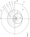
Figure 1 is shown one embodiment of lens of the invention.Lens 10 ofFigure 1 has an anterior surface, as shown, and a posterior surface, that is not shown.Lines optic zone 11 surrounded by non-opticallenticular zone 15. The stabilization feature of the lens, also not shown, may be any of the known stabilization types and will be located withinlenticular zone 15.Optic zone 11 has an inner distance vision zone 14, an outerdistance vision zone 12, and anear vision zone 13. The centers ofdistance zones 14 and 12 are located at the geometric center of theoptic zone 11. - Distance vision zone 14 lies within
near vision zone 13 such that the superior-most border ofnear vision zone 13 is tangential to the superior border of distance zone 14. The center ofnear vision zone 13 is located substantially along thevertical meridian 110 at about y = -1.63 mm. The inferior-most border ofnear vision zone 13 is tangential to the inferior-most border ofdistance vision zone 12. The remainder ofdistance vision zone 12 surrounds nearvision zone 13. For convenience, the boundaries of the various zones in all of the figures are shown as discrete lines. However, one ordinarily skilled in the art will recognize that the boundaries may be blended or aspheric. - A second embodiment of the lens of the invention is shown in
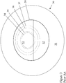
Figure 2 . Onlens 20 ofFigure 2 ,lines optic zone 21 is surrounded by non-opticallenticular zone 30.Optic zone 21 contains outerdistance vision zone 22 and innerdistance vision zone 24 as well as outer and innernear vision zones distance zones optic zone 21.Distance vision zone 24 lies withinnear vision zone 25 and is located such that its superior-most border is tangential to the superior-most border ofdistance vision zone 24. Nearvision zone 25 is centered substantially along thevertical meridian 210 at about y = -1.63 mm. The inferior-most border ofnear vision zone 25 is coincident with inferior-most border ofdistance vision zone 22. - Inner
near vision zone 23 lies within the inferior-most portion ofdistance vision zone 24 with its superior-most border at or below thehorizontal meridian 200. The inferior border ofnear vision zone 23 is tangential to the inferior border ofdistance zone 24. Nearvision zone 23 is centered substantially along thevertical meridian 210 at about y = -0.74 mm. - As shown, and preferably, both the near and distance vision zones are on one surface of the lens. However, the zones may be split between the anterior and posterior surfaces of the lens.
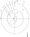
- Yet another embodiment of the lens of the invention is shown in
Figure 7 . Onlens 70 ofFigure 7 ,lines optic zone 71 is surrounded by non-opticallenticular zone 75.Optic zone 71 containsdistance vision zone 73 and inner and outer nearzones near zones optic zone 71.Distance vision zone 73 lies withinnear vision zone 72 and is located such that its superior-most border is tangential to the superior-most border ofnear vision zone 72.Distance vision zone 73 is centered substantially along thevertical meridian 710 at about y = +3.2 mm. The inferior-most border ofnear vision zone 74 is coincident with inferior-most border ofdistance vision zone 73. - In one embodiment, the ratio of the lens' optic zone area devoted to distance and near optical power are equal in both lenses of a lens pair worn by an individual. In another embodiment, the ratio of the lens' optic zone area devoted to the distance and near optical powers must be such that more area is devoted to the distance power for the dominant eye and more lens area will be devoted to the near vision power in the non-dominant eye. The preferred areas, on a percentage basis, for both the dominant and non-dominant eye lenses are disclosed in United States Patent Nos.
5,835,192 ,5,485,228 , and5,448,312 . - The lenses of the invention preferably incorporate a feature to assure that the lens translates while on-eye. Examples of features for ensuring translation are known in the art and include, without limitation, prism ballast, incorporating one or more ramps, ledges or the like in the inferior portion of the lens, truncation of the lens and the like. These features, as well as additional features useful for achieving translation of a lens on-eye are disclosed in United States Patents Nos.
4,618,227 ,5,141,301 ,5,245,366 ,5,483,304 ,5,606,378 ,6,092,899 , as well asU.S. Patent Application Publication No. 20040017542 . - The translation feature typically will also serve to rotationally stabilize the lens on-eye. However, it may be desirable to incorporate a separate stabilization zone in the lens. Suitable stabilization can be accomplished by incorporating one or more of the following into the lens: decentering the lens' front surface relative to the back surface, thickening of the inferior lens periphery, forming depressions or elevations on the lens' surface, using thin zones, or areas in which the thickness of the lens' periphery is reduced and the like and combinations thereof.
- The contact lenses of the invention may be either hard or soft lenses, but preferably are soft contact lenses. Soft contact lenses, made of any material suitable for producing such lenses, preferably are used. Suitable preferred materials for forming soft contact lenses using the method of the invention include, without limitation, silicone elastomers, silicone-containing macromers including, without limitation, those disclosed in United States Patent Nos.
5,371,147 ,5,314,960 , and5,057,578 , hydrogels, silicone-containing hydrogels, and the like and combinations thereof. More preferably, the lens material contains a siloxane functionality, including, without limitation, polydimethyl siloxane macromers, methacryloxypropyl polyalkyl siloxanes, and
mixtures thereof, a silicone hydrogel or a hydrogel, made of monomers containing hydroxy groups, carboxyl groups, or combinations thereof. Materials for making soft contact lenses are well known and commercially available. Preferably, the material is acquafilcon, etafilcon, genfilcon, lenefilcon, balafilcon, lotrafilcon, or galyfilcon. - The lenses of the invention may have any of a variety of corrective optical characteristics incorporated onto the surfaces in addition to distance and near optical powers, such as, for example, cylinder power.
- The lenses of the invention may be formed by any conventional method. For example, the zones formed therein may produced by diamond-turning using alternating radii. The zones may be diamond-turned into the molds that are used to form the lens of the invention. Subsequently, a suitable liquid resin is placed between the molds followed by compression and curing of the resin to form the lenses of the invention. Alternatively, the zones may be diamond-turned into lens buttons.
- The invention may be further clarified by a consideration of the following examples.
- A lens in accordance with
Figure 1 is provided. Referring toFigure 1 ,optic zone 11 has an outerdistance vision zone 12 with a diameter of 8 mm and an inner distance vision zone 14 with a diameter of 1.60 mm. Nearvision zone 13 is 1.60 mm in diameter.Dotted lines - The distance percentage within the pupil area was calculated for each pupil size and at pupil locations of y = 0 and y = -1.5 mm from a distance reference point that is located at y = 0.8 mm, meaning a point along the 90-270 degree meridian that is 0.8 mm superiorly from the 0-180 degree meridian. The results in Table 1 demonstrate that the lens design produces a pupil independent distance percentage for both y = 0 and y = -1.5 mm meaning that, at y = 0, the distance percentage is > 50 &, at y = -1.5, is < 50 %, and the percentages are relatively constant with pupil size.
Table 1 Example 1 3.0 mm 3.5 mm 5.0 mm 6.0 mm Average 0.0 mm 90 % 80 % 73 % 69 % 78 % -1.5 mm 27 % 24 % 32 % 39 % 31 % - A lens in accordance with
Figure 2 is provided. Referring toFigure 2 ,optic zone 21 has an outerdistance vision zone 22 with a diameter of 8 mm and an innerdistance vision zone 24 with a diameter 2.10 mm. An innernear vision zone 23 is of a diameter of 1.04 mm and an outernear vision zone 25 is of a diameter of 4.74 mm.Dotted lines - The pupil sizes are analyzed for the percentage of distance power within the pupil area at y = 0 and y = -1.5 for the distance reference point of y = 0.8 mm. The results in Table 2 demonstrate that the lens design produces a pupil independent distance to near ratio for y = 0 and y = 1.5.
Table 2 Example 2 3.0 mm 3.5 mm 5.0 mm 6.0 mm Average 0.0 mm 80 % 75 % 71 % 67 % 73 % -1.5 mm 25 % 25 % 29 % 38 % 30% - A prior art translating bifocal contact lens of the design shown in
Figure 3 . Referring toFigure 3 ,lens 30 has a surface on which there is alenticular zone 37 and anoptic zone 39.Optic zone 39 has a diameter of 8 mm and contains adistance vision zone 31 in its superior portion andnear vision zone 32 in its inferior portion. The boundary between the distance and near vision zones is located at y = -0.44 mm. The horizontal meridian is line 300. The distance reference point is at y = 0.8 mm. Pupil sizes of 3.0, 3.5, 5.0 and 6.0, shown as dottedlines Table 3 Example 2 3.0 mm 3.5 mm 5.0 mm 6.0 mm Average 0.0 mm 100 % 94 % 85 % 76 % 89 % -1.5 mm 34 % 37% 42 % 41 % 39 % - A second prior art translating bifocal contact lens of the design shown in
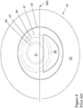
Figure 4 . Referring toFigure 4 ,lens 40 has a surface on which there is alenticular zone 43 and anoptic zone 49.Optic zone 49 has a diameter of 8 mm and contains adistance vision zone 41 and anear vision zone 42. The near segment is located at 0.6 mm below thehorizontal meridian 400. The distance reference point is at y = 0.8 mm. Pupil sizes of 3.0, 3.5, 5.0 and 6.0, shown as dottedlines Table 4 Example 2 3.0 mm 3.5 mm 5.0 mm 6.0 mm Average 0.0 mm 100 % 94 % 85 % 76 % 89 % -1.5 mm 34 % 37 % 42 % 50 % 41 % - A third prior art translating bifocal contact lens of the design shown in
Figure 5 . Referring toFigure 5 ,lens 50 has a surface on which there is alenticular zone 53 and anoptic zone 59.Optic zone 59 has a diameter of 8 mm and contains a centrally locateddistance vision zone 51 having a diameter of 4.20 mm with a annularnear vision zone 52 surrounding the distance vision zone. The distance reference point is at y = 0.0 mm. Pupil sizes of 3.0, 3.5, 5.0 and 6.0, shown as dottedlines
dependent at y = 0 mm with percentages between 50 and 99 %. Also, with pupil sizes of < 3.0 mm, a greater than 1.5 mm translation distance is required to reduce the distance percentage < 50 %.Table 5 0.0 mm 99 % 99 % 73 % 50 % 80 % 24 % -1.5 mm 54 % 52 % 45 % 39 % 48 % 7 % - A fourth prior art translating bifocal contact lens of the design shown in
Figure 6 . Referring toFigure 6 ,lens 60 has a surface on which there is alenticular zone 63 and anoptic zone 69.Optic zone 69 has a diameter of 8 mm and contains adistance vision zone 61 with anear vision zone 62 having a diameter of 4.20 mm. The superior-most boundary ofnear vision zone 62 is located approximately 0.3 mm above the geometric center ofoptic zone 69. The distance reference point is at y = 1.0 mm. Pupil sizes of 3.0, 3.5, 5.0 and 6.0, shown as dottedlines Table 6 Example 2 3.0 mm 3.5 mm 5.0 mm 6.0 mm Average 0.0 mm 78 % 74 % 74 % 71 % 74 % -1.5 mm 5 % 15 % 37 % 45 % 25 %
Claims (3)
- A translating contact lens (10, 20), comprising a horizontal meridian (100, 200), vertical meridian (110, 210) and an optic zone (11, 21), the optic zone (11, 21) comprising a first (14, 24) and a second (12, 22) distance vision zone each centered at a geometric center of the optic zone (11, 21) and a near vision zone (13, 25) characterised in that: the near vision zone (13, 25) has a center located below the geometric center of the optic zone (11, 21) at about y = -1.63 mm along the vertical meridian (110, 210), wherein the first distance vision zone (14, 24) lies within the near vision zone (13, 25) such that a superior-most border of the near vision zone (13, 25) is tangential to a superior border of the first distance vision zone (14, 24), and the near vision zone (13, 25) lies within the second distance vision zone (12, 22) such that an inferior-most border of the near vision zone (13, 25) is tangential to the inferior-most border of the second distance vision zone(12, 22).
- The translating contact lens (20) of claim 1, wherein the near vision zone (25) comprises a first near vision zone (25) and the optic zone (21) further comprises a second near vision zone (23), the second near vision zone (23) being centered below the geometric center of the optic zone (21) at y = -0.74 along the vertical meridian (210), wherein the second near vision zone (23) and the first distance vision zone (24) lie within the second distance vision zone (22), the second near vision zone (23) lies within the first near vision zone (25), and the second near vision zone (23) lies within the first distance vision zone (24), an inferior-most border of second near vision zone (23) being tangential with an inferior-most border of the first distance vision zone (24).
- A translating contact lens (70), comprising a horizontal meridian (700), vertical meridian (710) and an optic zone (71), the optic zone (71) comprising a first (72) and a second (74) near vision zone each centered at a geometric center of the optic zone (71) and a distance vision zone (73) characterised in that: the distance vision zone (73) has a center located above the geometric center of the optic zone (71) at about y = +3.2 mm along the vertical meridian (710), wherein the distance vision zone (73) lies within the first near vision zone (72) such that a superior-most border of the distance vision zone (73) is tangential to a superior border of the first near vision zone (72), and the second near vision zone (74) lies within the distance vision zone (73) such that an inferior-most border of the second near vision zone (74) is tangential to the inferior-most border of the distance vision zone (73).
Applications Claiming Priority (2)
| Application Number | Priority Date | Filing Date | Title |
|---|---|---|---|
| US11/427,525 US7503652B2 (en) | 2006-06-29 | 2006-06-29 | Translating multifocal ophthalmic lenses |
| PCT/US2007/072239 WO2008002976A2 (en) | 2006-06-29 | 2007-06-27 | Translating multifocal ophthalmic lenses |
Publications (2)
| Publication Number | Publication Date |
|---|---|
| EP2038696A2 EP2038696A2 (en) | 2009-03-25 |
| EP2038696B1 true EP2038696B1 (en) | 2018-11-14 |
Family
ID=38819291
Family Applications (1)
| Application Number | Title | Priority Date | Filing Date |
|---|---|---|---|
| EP07799081.0A Active EP2038696B1 (en) | 2006-06-29 | 2007-06-27 | Translating multifocal ophthalmic lenses |
Country Status (13)
| Country | Link |
|---|---|
| US (1) | US7503652B2 (en) |
| EP (1) | EP2038696B1 (en) |
| JP (1) | JP5538886B2 (en) |
| KR (1) | KR101393453B1 (en) |
| CN (1) | CN101479647B (en) |
| AR (1) | AR061757A1 (en) |
| AU (1) | AU2007265030B2 (en) |
| BR (1) | BRPI0713549B1 (en) |
| CA (1) | CA2655815C (en) |
| HK (1) | HK1134343A1 (en) |
| RU (1) | RU2439632C2 (en) |
| TW (1) | TWI426320B (en) |
| WO (1) | WO2008002976A2 (en) |
Families Citing this family (24)
| Publication number | Priority date | Publication date | Assignee | Title |
|---|---|---|---|---|
| US7753521B2 (en) * | 2008-03-31 | 2010-07-13 | Johnson & Johnson Vision Care, Inc. | Lenses for the correction of presbyopia and methods of designing the lenses |
| CH701866A1 (en) | 2009-09-30 | 2011-03-31 | Aha Informatik Ag | Contacts with eccentrically applied bifocal correction. |
| EP2622403A1 (en) | 2010-09-27 | 2013-08-07 | Johnson & Johnson Vision Care Inc. | Translating presbyopic contact lens |
| AU2011312605B2 (en) | 2010-09-27 | 2014-08-07 | Johnson & Johnson Vision Care, Inc. | Translating presbyopic contact lens |
| RU2552606C2 (en) | 2010-09-27 | 2015-06-10 | Джонсон Энд Джонсон Вижн Кэа, Инк. | Asymmetric displaceable contact lens |
| US8801176B2 (en) | 2011-03-24 | 2014-08-12 | Johnson & Johnson Vision Care, Inc. | Contact lenses with improved movement |
| US8672476B2 (en) | 2011-03-24 | 2014-03-18 | Johnson & Johnson Vision Care, Inc. | Contact lenses with improved movement |
| US9028063B2 (en) * | 2011-08-26 | 2015-05-12 | Johnson & Johnson Vision Care, Inc. | Translating presbyopic contact lens pair |
| US9046698B2 (en) * | 2012-02-28 | 2015-06-02 | Johnson & Johnson Vision Care, Inc. | Multi-axis lens design for astigmatism |
| AU2013232736B2 (en) * | 2012-03-14 | 2016-10-13 | Brien Holden Vision Institute | Lens for myopic eye |
| TWI588560B (en) | 2012-04-05 | 2017-06-21 | 布萊恩荷登視覺協會 | Lenses, devices, methods and systems for refractive error |
| US9201250B2 (en) | 2012-10-17 | 2015-12-01 | Brien Holden Vision Institute | Lenses, devices, methods and systems for refractive error |
| EP2908773B1 (en) | 2012-10-17 | 2024-01-03 | Brien Holden Vision Institute | Lenses, devices, methods and systems for refractive error |
| US10302968B2 (en) | 2013-01-28 | 2019-05-28 | Onefocus Vision, Inc. | Fluidic module for accommodating soft contact lens |
| KR20160006156A (en) | 2013-01-28 | 2016-01-18 | 원포커스 테크날러지 엘엘씨 | Accommodating soft contact lens |
| CA2899442A1 (en) | 2013-01-30 | 2014-08-07 | Onefocus Technology, Llc | Manufacturing process of an accommodating soft contact lens |
| US9116363B2 (en) * | 2013-05-17 | 2015-08-25 | Johnson & Johnson Vision Care, Inc. | System and method of programming an energized ophthalmic lens |
| PL404250A1 (en) | 2013-06-07 | 2014-12-08 | Quest Optical Industries Ltd | Bifocal non-progressive optical lens |
| EP3084486A4 (en) | 2013-12-20 | 2017-11-22 | Onefocus Vision, LLC | Fluidic module for accomodating soft contact lens |
| US9618774B2 (en) | 2014-02-10 | 2017-04-11 | Shamir Optical Industry Ltd. | Quasi progressive lenses for eyewear |
| JP2019505010A (en) | 2015-11-11 | 2019-02-21 | ワンフォーカス ビジョン, インコーポレイテッド | Perspective adjustment lens with cavity |
| KR101870142B1 (en) * | 2016-08-12 | 2018-06-25 | 이성준 | Contact lenses for presbyopia |
| US9933633B1 (en) | 2016-11-08 | 2018-04-03 | Paul Douglas Becherer | Bifocal contact lenses providing reduced glare and blurriness in dim lighting |
| CN108646434A (en) * | 2018-06-29 | 2018-10-12 | 重庆视力派眼镜连锁有限公司 | One kind is for correcting presbyopic eyeglass |
Family Cites Families (24)
| Publication number | Priority date | Publication date | Assignee | Title |
|---|---|---|---|---|
| US461827A (en) * | 1891-10-27 | ferry | ||
| US4618227A (en) | 1983-10-07 | 1986-10-21 | Vistakon, Inc. | Soft contact lens |
| US4693572A (en) * | 1985-06-03 | 1987-09-15 | Fused Kontacts Of Chicago, Inc. | Monocentric bifocal corneal contact lens |
| US4923296A (en) * | 1988-07-14 | 1990-05-08 | Erickson Paul M | Oriented simultaneous vision bifocal contact lenses or the like utilizing introaocular suppression of blur |
| JPH05323242A (en) * | 1991-01-31 | 1993-12-07 | Shiro Sato | Dual focus contact lens with jumpless image |
| US5141301A (en) * | 1991-04-25 | 1992-08-25 | Morstad David P | Soft bifocal contact lens |
| US5198844A (en) * | 1991-07-10 | 1993-03-30 | Johnson & Johnson Vision Products, Inc. | Segmented multifocal contact lens |
| US5483304A (en) * | 1991-07-26 | 1996-01-09 | Hanita Lenses | Multifocal contact lens |
| US5245366A (en) * | 1991-10-31 | 1993-09-14 | Svochak Jan B | Bifocal contact lens and method of making same |
| SK377492A3 (en) * | 1992-01-28 | 1995-05-10 | Johnson & Johnson Vision Prod | Multifocal refracting lens and method of its manufacture |
| US5448312A (en) * | 1992-12-09 | 1995-09-05 | Johnson & Johnson Vision Products, Inc. | Pupil-tuned multifocal ophthalmic lens |
| FR2704327B1 (en) * | 1993-04-23 | 1995-06-23 | Essilor Int | Pair of progressive multifocal ophthalmic lenses. |
| NL9301863A (en) * | 1993-10-28 | 1995-05-16 | Meurs Optiek B V Van | Contact lens with an optical zone with at least one focus. |
| DE29680953U1 (en) * | 1995-10-31 | 1997-11-06 | Procornea Holding Bv | Multifocal lens |
| EP0822439A4 (en) * | 1996-02-21 | 2007-01-31 | Seiko Epson Corp | Multifocal contact lens |
| JP4023902B2 (en) | 1998-04-10 | 2007-12-19 | 株式会社メニコン | Toric multifocal lens |
| JP2000122007A (en) * | 1998-10-19 | 2000-04-28 | Menicon Co Ltd | Multifocus type ocular lens |
| US6286956B1 (en) | 1998-10-19 | 2001-09-11 | Mencion Co., Ltd. | Multifocal ocular lens including intermediate vision correction region between near and distant vision correction regions |
| US6773107B2 (en) * | 2000-08-17 | 2004-08-10 | Novartis Ag | Soft translating contact lens for presbyopia |
| US6746118B2 (en) * | 2001-07-17 | 2004-06-08 | Soft Focal Company, Inc. | Bifocal contact lens with secondary prism |
| US6921168B2 (en) * | 2002-07-24 | 2005-07-26 | Novartis Ag | Translating contact lens having a ramped ridge |
| US6871953B1 (en) * | 2003-09-29 | 2005-03-29 | Softfocal Company, Inc. | Contact lens with transition |
| US7080906B2 (en) * | 2003-11-12 | 2006-07-25 | Novartis Ag | Translating bifocal wear modality |
| US7044597B2 (en) * | 2003-12-16 | 2006-05-16 | Bausch & Lomb Incorporated | Multifocal contact lens and method of manufacture thereof |
-
2006
- 2006-06-29 US US11/427,525 patent/US7503652B2/en active Active
-
2007
- 2007-06-27 CN CN2007800245789A patent/CN101479647B/en active Active
- 2007-06-27 AU AU2007265030A patent/AU2007265030B2/en not_active Ceased
- 2007-06-27 WO PCT/US2007/072239 patent/WO2008002976A2/en active Application Filing
- 2007-06-27 EP EP07799081.0A patent/EP2038696B1/en active Active
- 2007-06-27 CA CA2655815A patent/CA2655815C/en active Active
- 2007-06-27 KR KR1020097001708A patent/KR101393453B1/en active IP Right Grant
- 2007-06-27 JP JP2009518536A patent/JP5538886B2/en not_active Expired - Fee Related
- 2007-06-27 RU RU2009102836/28A patent/RU2439632C2/en active
- 2007-06-27 BR BRPI0713549-1A patent/BRPI0713549B1/en not_active IP Right Cessation
- 2007-06-28 TW TW096123397A patent/TWI426320B/en active
- 2007-06-29 AR ARP070102930A patent/AR061757A1/en active IP Right Grant
-
2009
- 2009-11-11 HK HK09110521.8A patent/HK1134343A1/en not_active IP Right Cessation
Non-Patent Citations (1)
| Title |
|---|
| None * |
Also Published As
| Publication number | Publication date |
|---|---|
| RU2009102836A (en) | 2010-08-10 |
| US20080002148A1 (en) | 2008-01-03 |
| AU2007265030B2 (en) | 2013-05-30 |
| KR101393453B1 (en) | 2014-05-13 |
| WO2008002976A2 (en) | 2008-01-03 |
| CA2655815A1 (en) | 2008-01-03 |
| WO2008002976A3 (en) | 2008-03-20 |
| BRPI0713549A2 (en) | 2012-03-20 |
| US7503652B2 (en) | 2009-03-17 |
| AU2007265030A1 (en) | 2008-01-03 |
| AR061757A1 (en) | 2008-09-17 |
| CN101479647A (en) | 2009-07-08 |
| TWI426320B (en) | 2014-02-11 |
| JP2009543136A (en) | 2009-12-03 |
| TW200815820A (en) | 2008-04-01 |
| BRPI0713549B1 (en) | 2018-07-31 |
| JP5538886B2 (en) | 2014-07-02 |
| RU2439632C2 (en) | 2012-01-10 |
| HK1134343A1 (en) | 2010-04-23 |
| EP2038696A2 (en) | 2009-03-25 |
| CN101479647B (en) | 2011-02-02 |
| CA2655815C (en) | 2015-10-27 |
| KR20090036118A (en) | 2009-04-13 |
Similar Documents
| Publication | Publication Date | Title |
|---|---|---|
| EP2038696B1 (en) | Translating multifocal ophthalmic lenses | |
| EP0742463B1 (en) | Method of producing a spherical power multifocal ophthalmic lens for correcting an astigmatic presbyopic eye | |
| CA2421001C (en) | Ophthalmic lenses useful in correcting astigmatism and presbyopia | |
| EP0742465B1 (en) | Multifocal toric contact lenses | |
| EP2748673B1 (en) | Translating presbyopic contact lens pair | |
| AU2001286764A1 (en) | Ophthalmic lenses useful in correcting astigmatism and presbyopia | |
| KR101848606B1 (en) | Asymmetric translating presbyopic contact lens | |
| AU2011307360B2 (en) | Translating presbyopic contact lens | |
| CA2647517A1 (en) | Multifocal contact lenses | |
| AU2007313874A1 (en) | Method for designing multifocal contact lenses | |
| US9170434B2 (en) | Translating presbyopic contact lens | |
| CN116368424A (en) | Contact lenses for preventing or slowing progression or worsening of myopia and related methods | |
| AU2015203718A1 (en) | Method for designing multifocal contact lenses | |
| AU2013273828A1 (en) | Method for designing multifocal contact lenses |
Legal Events
| Date | Code | Title | Description |
|---|---|---|---|
| PUAI | Public reference made under article 153(3) epc to a published international application that has entered the european phase |
Free format text: ORIGINAL CODE: 0009012 |
|
| 17P | Request for examination filed |
Effective date: 20090123 |
|
| AK | Designated contracting states |
Kind code of ref document: A2 Designated state(s): DE FR GB IE IT |
|
| RBV | Designated contracting states (corrected) |
Designated state(s): DE FR GB IE IT |
|
| DAX | Request for extension of the european patent (deleted) | ||
| REG | Reference to a national code |
Ref country code: HK Ref legal event code: DE Ref document number: 1129737 Country of ref document: HK |
|
| 17Q | First examination report despatched |
Effective date: 20160817 |
|
| GRAP | Despatch of communication of intention to grant a patent |
Free format text: ORIGINAL CODE: EPIDOSNIGR1 |
|
| INTG | Intention to grant announced |
Effective date: 20180712 |
|
| GRAS | Grant fee paid |
Free format text: ORIGINAL CODE: EPIDOSNIGR3 |
|
| GRAA | (expected) grant |
Free format text: ORIGINAL CODE: 0009210 |
|
| AK | Designated contracting states |
Kind code of ref document: B1 Designated state(s): DE FR GB IE IT |
|
| REG | Reference to a national code |
Ref country code: GB Ref legal event code: FG4D |
|
| REG | Reference to a national code |
Ref country code: DE Ref legal event code: R096 Ref document number: 602007056832 Country of ref document: DE |
|
| REG | Reference to a national code |
Ref country code: IE Ref legal event code: FG4D |
|
| REG | Reference to a national code |
Ref country code: DE Ref legal event code: R097 Ref document number: 602007056832 Country of ref document: DE |
|
| PLBE | No opposition filed within time limit |
Free format text: ORIGINAL CODE: 0009261 |
|
| STAA | Information on the status of an ep patent application or granted ep patent |
Free format text: STATUS: NO OPPOSITION FILED WITHIN TIME LIMIT |
|
| 26N | No opposition filed |
Effective date: 20190815 |
|
| PGFP | Annual fee paid to national office [announced via postgrant information from national office to epo] |
Ref country code: IT Payment date: 20220510 Year of fee payment: 16 Ref country code: IE Payment date: 20220510 Year of fee payment: 16 Ref country code: GB Payment date: 20220506 Year of fee payment: 16 Ref country code: FR Payment date: 20220510 Year of fee payment: 16 Ref country code: DE Payment date: 20220505 Year of fee payment: 16 |
|
| REG | Reference to a national code |
Ref country code: DE Ref legal event code: R119 Ref document number: 602007056832 Country of ref document: DE |
|
| GBPC | Gb: european patent ceased through non-payment of renewal fee |
Effective date: 20230627 |
|
| REG | Reference to a national code |
Ref country code: IE Ref legal event code: MM4A |
|
| PG25 | Lapsed in a contracting state [announced via postgrant information from national office to epo] |
Ref country code: IE Free format text: LAPSE BECAUSE OF NON-PAYMENT OF DUE FEES Effective date: 20230627 |