EP2038585B1 - Conveying temperature information in a controlled variable speed heating, ventilation, and air conditioning (hvac) system - Google Patents
Conveying temperature information in a controlled variable speed heating, ventilation, and air conditioning (hvac) system Download PDFInfo
- Publication number
- EP2038585B1 EP2038585B1 EP07825328.3A EP07825328A EP2038585B1 EP 2038585 B1 EP2038585 B1 EP 2038585B1 EP 07825328 A EP07825328 A EP 07825328A EP 2038585 B1 EP2038585 B1 EP 2038585B1
- Authority
- EP
- European Patent Office
- Prior art keywords
- compressor
- signal
- temperature difference
- duty cycle
- thermostat
- Prior art date
- Legal status (The legal status is an assumption and is not a legal conclusion. Google has not performed a legal analysis and makes no representation as to the accuracy of the status listed.)
- Active
Links
Images





Classifications
-
- F—MECHANICAL ENGINEERING; LIGHTING; HEATING; WEAPONS; BLASTING
- F24—HEATING; RANGES; VENTILATING
- F24F—AIR-CONDITIONING; AIR-HUMIDIFICATION; VENTILATION; USE OF AIR CURRENTS FOR SCREENING
- F24F11/00—Control or safety arrangements
- F24F11/70—Control systems characterised by their outputs; Constructional details thereof
- F24F11/80—Control systems characterised by their outputs; Constructional details thereof for controlling the temperature of the supplied air
- F24F11/83—Control systems characterised by their outputs; Constructional details thereof for controlling the temperature of the supplied air by controlling the supply of heat-exchange fluids to heat-exchangers
-
- F—MECHANICAL ENGINEERING; LIGHTING; HEATING; WEAPONS; BLASTING
- F24—HEATING; RANGES; VENTILATING
- F24F—AIR-CONDITIONING; AIR-HUMIDIFICATION; VENTILATION; USE OF AIR CURRENTS FOR SCREENING
- F24F11/00—Control or safety arrangements
- F24F11/70—Control systems characterised by their outputs; Constructional details thereof
- F24F11/80—Control systems characterised by their outputs; Constructional details thereof for controlling the temperature of the supplied air
- F24F11/86—Control systems characterised by their outputs; Constructional details thereof for controlling the temperature of the supplied air by controlling compressors within refrigeration or heat pump circuits
-
- F—MECHANICAL ENGINEERING; LIGHTING; HEATING; WEAPONS; BLASTING
- F25—REFRIGERATION OR COOLING; COMBINED HEATING AND REFRIGERATION SYSTEMS; HEAT PUMP SYSTEMS; MANUFACTURE OR STORAGE OF ICE; LIQUEFACTION SOLIDIFICATION OF GASES
- F25B—REFRIGERATION MACHINES, PLANTS OR SYSTEMS; COMBINED HEATING AND REFRIGERATION SYSTEMS; HEAT PUMP SYSTEMS
- F25B49/00—Arrangement or mounting of control or safety devices
- F25B49/02—Arrangement or mounting of control or safety devices for compression type machines, plants or systems
- F25B49/025—Motor control arrangements
-
- G—PHYSICS
- G05—CONTROLLING; REGULATING
- G05D—SYSTEMS FOR CONTROLLING OR REGULATING NON-ELECTRIC VARIABLES
- G05D23/00—Control of temperature
- G05D23/19—Control of temperature characterised by the use of electric means
- G05D23/1906—Control of temperature characterised by the use of electric means using an analogue comparing device
- G05D23/1913—Control of temperature characterised by the use of electric means using an analogue comparing device delivering a series of pulses
-
- G—PHYSICS
- G05—CONTROLLING; REGULATING
- G05D—SYSTEMS FOR CONTROLLING OR REGULATING NON-ELECTRIC VARIABLES
- G05D23/00—Control of temperature
- G05D23/19—Control of temperature characterised by the use of electric means
- G05D23/20—Control of temperature characterised by the use of electric means with sensing elements having variation of electric or magnetic properties with change of temperature
- G05D23/24—Control of temperature characterised by the use of electric means with sensing elements having variation of electric or magnetic properties with change of temperature the sensing element having a resistance varying with temperature, e.g. a thermistor
-
- F—MECHANICAL ENGINEERING; LIGHTING; HEATING; WEAPONS; BLASTING
- F25—REFRIGERATION OR COOLING; COMBINED HEATING AND REFRIGERATION SYSTEMS; HEAT PUMP SYSTEMS; MANUFACTURE OR STORAGE OF ICE; LIQUEFACTION SOLIDIFICATION OF GASES
- F25B—REFRIGERATION MACHINES, PLANTS OR SYSTEMS; COMBINED HEATING AND REFRIGERATION SYSTEMS; HEAT PUMP SYSTEMS
- F25B2600/00—Control issues
- F25B2600/02—Compressor control
- F25B2600/021—Inverters therefor
-
- F—MECHANICAL ENGINEERING; LIGHTING; HEATING; WEAPONS; BLASTING
- F25—REFRIGERATION OR COOLING; COMBINED HEATING AND REFRIGERATION SYSTEMS; HEAT PUMP SYSTEMS; MANUFACTURE OR STORAGE OF ICE; LIQUEFACTION SOLIDIFICATION OF GASES
- F25B—REFRIGERATION MACHINES, PLANTS OR SYSTEMS; COMBINED HEATING AND REFRIGERATION SYSTEMS; HEAT PUMP SYSTEMS
- F25B2600/00—Control issues
- F25B2600/02—Compressor control
- F25B2600/025—Compressor control by controlling speed
- F25B2600/0251—Compressor control by controlling speed with on-off operation
-
- F—MECHANICAL ENGINEERING; LIGHTING; HEATING; WEAPONS; BLASTING
- F25—REFRIGERATION OR COOLING; COMBINED HEATING AND REFRIGERATION SYSTEMS; HEAT PUMP SYSTEMS; MANUFACTURE OR STORAGE OF ICE; LIQUEFACTION SOLIDIFICATION OF GASES
- F25B—REFRIGERATION MACHINES, PLANTS OR SYSTEMS; COMBINED HEATING AND REFRIGERATION SYSTEMS; HEAT PUMP SYSTEMS
- F25B2600/00—Control issues
- F25B2600/02—Compressor control
- F25B2600/025—Compressor control by controlling speed
- F25B2600/0253—Compressor control by controlling speed with variable speed
-
- F—MECHANICAL ENGINEERING; LIGHTING; HEATING; WEAPONS; BLASTING
- F25—REFRIGERATION OR COOLING; COMBINED HEATING AND REFRIGERATION SYSTEMS; HEAT PUMP SYSTEMS; MANUFACTURE OR STORAGE OF ICE; LIQUEFACTION SOLIDIFICATION OF GASES
- F25B—REFRIGERATION MACHINES, PLANTS OR SYSTEMS; COMBINED HEATING AND REFRIGERATION SYSTEMS; HEAT PUMP SYSTEMS
- F25B2700/00—Sensing or detecting of parameters; Sensors therefor
- F25B2700/21—Temperatures
- F25B2700/2104—Temperatures of an indoor room or compartment
-
- Y—GENERAL TAGGING OF NEW TECHNOLOGICAL DEVELOPMENTS; GENERAL TAGGING OF CROSS-SECTIONAL TECHNOLOGIES SPANNING OVER SEVERAL SECTIONS OF THE IPC; TECHNICAL SUBJECTS COVERED BY FORMER USPC CROSS-REFERENCE ART COLLECTIONS [XRACs] AND DIGESTS
- Y02—TECHNOLOGIES OR APPLICATIONS FOR MITIGATION OR ADAPTATION AGAINST CLIMATE CHANGE
- Y02B—CLIMATE CHANGE MITIGATION TECHNOLOGIES RELATED TO BUILDINGS, e.g. HOUSING, HOUSE APPLIANCES OR RELATED END-USER APPLICATIONS
- Y02B30/00—Energy efficient heating, ventilation or air conditioning [HVAC]
- Y02B30/70—Efficient control or regulation technologies, e.g. for control of refrigerant flow, motor or heating
Definitions
- the present invention relates generally to the field of controlling a variable speed heating, ventilation, and air conditioning (HVAC) system, and more particularly to sending a signal that conveys a temperature difference from a thermostat unit to a controller unit.
- HVAC variable speed heating, ventilation, and air conditioning
- HVAC heating, ventilation, and air conditioning
- MCU microprocessor controller unit
- DSP digital signal processor
- the speed (revolutions per unit time) of a variable speed controlled compressor depends on the temperature difference of the set temperature (typically set at a thermostat) and the ambient temperature of the temperature-controlled room. In general for the cooling function when the ambient temperature is higher than the set temperature, the higher the temperature difference, the faster the compressor should run.
- a typical thermostat can provide only a simple ON/OFF control of the 24V AC to a compressor controller that controls that compressor.
- a variable speed controlled compressor will not typically function at their maximum efficiency. Consequently, there is a need for apparatuses and methods that enable the typical thermostat to properly control a variable speed controlled compressor.
- the present invention provides methods and apparatuses that support the transfer of data from a thermostat unit to a controller unit to control the speed of a compressor of an air conditioner unit or a blower motor of a furnace.
- the invention is implemented by a system according to claim 1.
- the duty cycle of a signal that is sent from a thermostat unit to a compressor controller unit is adjusted in accordance with a temperature difference between the ambient temperature of an environmentally controlled space and a set temperature.
- the compressor controller unit measures the duty cycle to determine the temperature difference and adjusts the compressor speed in accordance with the temperature difference.
- US-4856 286 and US-5309730 disclose duty cycle compressor controller units.
- the duty cycle of a signal that is sent from a thermostat unit to a furnace controller unit is adjusted in accordance with a temperature difference between the ambient temperature of an environmentally controlled space and a set temperature.
- the furnace controller unit measures the duty cycle to determine the temperature difference and adjusts the speed of a blower motor in accordance with the temperature difference.
- the change in hardware at both the thermostat side and the compressor controller side is minimized.
- An AC line (e.g., 24 volts) is used to transfer data in a signal sent from the thermostat side to the compressor controller side.
- the signal is switched on and off, in which the AC waveform is conducted and blocked by the thermostat unit and received by the compressor controller. Consequently, existing wiring can be used without modifications.
- a thermostat unit instructs a compressor controller unit to stop operation immediately in an emergency situation by sending a signal with a pulse or pulses having a short time duration.
- a compressor controller unit measures the duty cycle of a received signal, determines the temperature from the duty cycle, and adjusts the compressor speed from a predetermined relationship.
- the compressor speed is related to the temperature difference, in which the compressor controller unit may access a lockup table using an address determined by the temperature difference.
- a pulse width modulated (PWM) controller is instructed by a microprocessor control unit to generate control pulses for the compressor so that the compressor runs at a desired speed.
- the PWM controller configures an IGBT (insulated-gate bipolar transistor) array so that an appropriate pulse stream is provided to the compressor.
- FIG. 1 shows a thermostat unit 100 for controlling a variable speed compressor (not shown) in accordance with an embodiment of the invention.
- Thermostat unit 100 includes microprocessor control unit (MCU) 107 and switching module 105.
- Switching module 105 which electrically turns on and off, may be implemented with a relay, triac, or field effect transistor (FET).
- thermostat unit 100 may include keypad input 111 in order for a user to input a set temperature or a profile of set temperatures (as will be discussed) and display 113 to display the ambient temperature of a controlled space (e.g., a room) and the set temperature.
- MCU microprocessor control unit
- FET field effect transistor
- switching module 105 is either in the "on” state or the “off” state.
- electrical conductivity is completed from line 101 to line 103 and an AC waveform (typically 24 volts AC) is provided to a compressor (for cooling) to a furnace control board (for heating).
- an AC waveform typically 24 volts AC
- the thermostat is supporting the cooling function (i.e., by communicating with a compressor controller to control a compressor as will be discussed).
- switching module 105 is either on or off, only two states are directly supported. However, in accordance with an aspect of the invention, information that is indicative of T diff is transmitted from thermostat unit 100 to compressor controller unit 300 (as shown in Figure 3 by varying the duty cycle of a signal (e.g., signal 200 as shown in Figure 2 ) that is conveyed by lines 101, 103.
- a signal e.g., signal 200 as shown in Figure 2
- thermostat unit 100 sends a special signal that has a short pulse duration to notify a furnace/air conditioner controller to immediately stop operation.
- the special signal can be four consecutive pulses with 1 second on and 1 second off.
- FIG 2 shows signal 200 that is sent from a thermostat unit 100 (as shown.in Figure 1 ) to a compressor controller unit 300 (as shown in Figure 3 ) for controlling a variable speed compressor 303 (as shown in Figure 3 ) in accordance with an embodiment of the invention.
- Signal 200 as shown in Figure 2 , spans a time duration over time periods 201, 203, and 205.
- signal 200 is being electrically conducted during an activated time duration (T on ) (e.g., activated time duration 201a for time period 201) and electrically blocked during an deactivated time duration (T off ) (e.g., deactivated time duration 201b for time period 201).
- activated time duration 201a AC power (corresponding to a 24 volts AC waveform) is conducted.
- deactivated time duration 201b AC power is not conducted.
- thermostat unit 100 notifies compressor unit 300 the value of T max by sending a configuration signal having a preamble followed by a number of pulses, in which the number of pulses is indicative of the value of T max .
- the preamble comprises a predetermined pulse sequence of two ON time periods followed by two OFF time periods, each time period being one second. For each ON time period, a pulse is generated for 0.5 second during an ON time period and not generated during an OFF time period.
- microprocessor control unit 107 controls switching module 105 to turn on and turn off signal 200 based on any period of time.
- the time period may vary from one time period to another.
- the time period may be 5, 10 or 15 minutes or any other time period.
- the duty cycle of signal 200 conveys information about the temperature difference (T diff ) as determined by microprocessor control unit 107. As suggested by Figure 2 , the duty cycle typically varies from one time period to another time period corresponding to temperature difference variations.
- FIG 3 shows compressor controller unit 300 for controlling a variable speed compressor 303 in accordance with an embodiment of the invention.
- Microprocessor control unit (MCU) 301 scans lines 101, 103 for signal 200 and detects a time between two rising signal edges (e.g., signal edges 251 and 253 as shown in Figure 2 ) to determine the current time period of signal 200.
- Microprocessor control unit 301 may be coupled with a digital signal processor in order to facilitate calculations.
- compressor controller unit 300 waits receives duty cycle information for an entire time period before further processing the information. For example, compressor controller unit 300 determines the duty cycle for time period 201 from signal 200 after detecting signal edge 253. Compressor controller unit 300 consequently determines the temperature difference T diff , as measured by thermostat unit 100, by decoding signal 200. (As will be discussed with Figure 8 , compressor controller unit 300 utilizes flow diagram 800 to measure the duty cycle.) Compressor controller unit 300 measures the duty cycle of signal 200 of the previous time period in accordance with EQ.
- T diff Measured_Duty_Cycle - 50 % / 50 % * T max If T diff is positive, variable speed compressor 303 should turn faster based on a predetermined relationship, e.g., relationship 503 as shown in Figure 5 as will be discussed. If T diff is negative, variable speed compressor 303 should turn slower based on an algorithm.
- compressor control unit 300 obtains T max by a user entering T max through keypad 309. While compressor controller unit 300 may obtain the value of T max from a configuration signal sent by thermostat unit 100, as previously discussed, the value of T max may be entered into keypad 111 by the user. Other embodiments of the invention may utilize a predetermined value of T max that is stored in memory.
- Microprocessor control unit 301 may access lookup data structure 317 in order to determine the temperature difference (T diff ) and the compressor speed. (As will be discussed, the compressor speed is determined as a function of the temperature difference as shown in Figure 5 .) In order to obtain a desired efficiency, compressor 303 typically runs at a higher speed as the temperature difference becomes greater. When the compressor speed has been determined, microprocessor control unit 301 instructs PWM (pulse width modulated) controller 305 to drive IGBT (insulated-gate bipolar transistor) array 307 (via bus 311) so that compressor 303 runs at the desired compressor speed (over bus 313). PWM controller 305 is provided an indication of the actual compressor speed over feedback connection 315 in order to adjust the compressor speed to obtain the desired compressor speed. An exemplary embodiment will be further discussed with Figure 9 .
- PWM pulse width modulated
- compressor controller unit 300 functions with a traditional thermostat design but with software modifications as will be discussed.
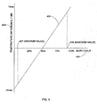
- Figure 4 shows relationship 405 between temperature difference (T diff ) 403, referencing an ambient temperature (of an environmentally controlled space where thermistor 109 is located) to a set temperature, and measured duty cycle 401 of a signal in accordance with an embodiment of the invention.
- relationship 405 is in accordance with EQ. 7, although other embodiments may utilize a different relationship between the temperature difference and the duty cycle.
- temperature difference 403 is determined to equal -0.5T max .
- microprocessor control unit 301 analyzes signal 200 in a time-interrupt basis as shown in Figure 8 . Depending on the value of the time interval between interrupts, microprocessor control unit 301 may not detect a transition of signal 200. (Between time-interrupts, microprocessor control unit 301 may be executing other tasks, e.g., diagnostics and executing commands entered through keypad 309.) Consequently, the temperature difference is limited between T max - ⁇ temp and - T max + ⁇ temp so that signal transitions can be detected. As the time durations between time-interrupts become smaller, the value of
- FIG. 5 shows relationship 503 of a determined compression speed 501 and the temperature difference 403 in accordance with an embodiment of the invention.
- Microprocessor control unit 301 measures duty cycle 401 and determines temperature difference 403 using relationship 405.
- microprocessor control unit 301 accesses lookup data structure 317 using an address determined by duty cycle 401 to obtain temperature difference 403.
- microprocessor control unit 301 subsequently accesses lookup data structure 317 to determine compression speed 501 using an address determined by temperature difference 403 to obtain compression speed 501. Because the temperature difference typically varies from time period to time period, as suggested by Figure 2 , compressor speed 501 consequently varies.
- FIG. 6 shows flow diagram 600 that is executed by microprocessor control unit 107 in accordance with an embodiment of the invention.
- Microprocessor control unit 107 obtains the set temperature T set , the time period (T cycle ), and the ambient temperature (T room ) from thermistor 109 in step 601.
- microprocessor control unit 107 determines the temperature difference (T diff ) in accordance with EQ. 1. If the temperature difference is larger than the maximum temperature difference (T max ), as determined by step 605, the temperature difference is limited to T max - 1 as determined by step 607. Otherwise, step 611 determines whether the temperature difference is less than the negative maximum temperature difference (-T max) in step 611. If so, the temperature difference is limited to -T max + 1 in step 613. Otherwise, the activated time duration (T on ) is determined in accordance with EQ. 5 in step 609. Signal 200 is generated in accordance with T on and To ff as determined by flow diagram 600.
- FIG. 7 shows flow diagram 700 that is executed by compressor controller unit 300 to initiate processing of signal 200, as shown in Figure 2 , during a time period.
- Microprocessor control unit 301 obtains T max and F def to initiate processing over the current time period. Consequently, microprocessor control unit 301 resets T on , T off , and sets the compressor speed variable F speed to F def in step 701.
- microprocessor control unit 301 determines whether signal 200 is present (i.e., whether any signal transitions have been detected.)
- interrupts are configured to occur periodically (every T interrupt time interval) so that pulse edges can be detected. For example, if the minimum pulse duration is 1 second (corresponding to an emergency stop), interrupts are configured to occur at least every 0.5 seconds.
- procedure 800 (as shown in Figure 8 ) is processed every T interrupt time interval.
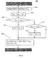
- FIG 8 shows flow diagram 800 that is executed by compressor controller unit 300 to process signal 200, as shown in Figure 2 , during a time period.
- flow diagram 800 determines whether there are signal edges detected in signal 200. If not, compressor 303 is not active.
- step 801 microprocessor control unit 301 determines if signal 200 is conducting AC power (typically 24 volts AC) during T on . If not, the T off counter is incremented in step 817. (In flow diagram 800, T off counter and T on counter are appropriately incremented so that the duty cycle can be determined when flow diagram is respectively executed during the current timer period. Once the current time period is completed, the duty cycle is determined by step 807 as will be discussed.) The process will exit (i.e., flow diagram 800 determines that the air conditioner is not active).
- AC power typically 24 volts AC
- microprocessor control unit 301 determines that signal 200 is conducting AC power during T on in step 801, microprocessor control unit 301 determines of signal 200 was previously in a non-conductive state (i.e., deactivated time duration 201b for time period 201) in step 805. If not, the T on counter is incremented in step 819, and process 800 is exited. If so, a rising signal edge is detected and step 807 is executed.
- step 807 the temperature difference is determined in accordance with EQ. 7 for the time period that has just completed.
- the T on counter and the T off counter are then reset.
- microprocessor control unit 301 determines the speed of compressor 303 in accordance with a predetermined function f(T diff ), e.g., relationship 503 as shown in Figure 5 .
- step 813 the compressor speed F speed is adjusted, in which microprocessor control unit 301 provides the updated compressor speed to PWM controller 305.
- Compressor 303 is consequently instructed to change its speed through bus 311, IGBT array 307, and bus 313.
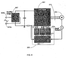
- Figure 9 shows an exemplary configuration for controlling variable speed compressor 303.
- compressor 303 comprises a three-phase motor; however, other embodiments may support other types of motors, e.g., single-phase induction motors, DC motors, and universal motors.
- Compressor 303 is powered by AC power lines 905a, 905b through rectifier bridge 907 and IGBT array 307.
- PWM controller 305 configures IGBT array 307 to control compressor 303 at the desired compressor speed.
- PWM controller 305 includes microcontroller 901 and gate drivers 903a-903c.
- the speed of compressor 303 is controlled by PWM controller 305, in which the voltage-to-frequency ratio is adjusted with a speed feedback configuration.
- Embodiments of the invention support a heating function in a HVAC system.
- a controller unit in conjunction with a thermostat unit, couples with a variable blower motor of a furnace.
- the speed of the variable blower motor is varied in accordance with characteristics of the motor and thermodynamics considerations.
- the computer system may include at least one computer such as a microprocessor, digital signal processor, and associated peripheral electronic circuitry.
Landscapes
- Engineering & Computer Science (AREA)
- Physics & Mathematics (AREA)
- Mechanical Engineering (AREA)
- General Engineering & Computer Science (AREA)
- Thermal Sciences (AREA)
- Chemical & Material Sciences (AREA)
- Combustion & Propulsion (AREA)
- General Physics & Mathematics (AREA)
- Automation & Control Theory (AREA)
- Air Conditioning Control Device (AREA)
Description
- The present invention relates generally to the field of controlling a variable speed heating, ventilation, and air conditioning (HVAC) system, and more particularly to sending a signal that conveys a temperature difference from a thermostat unit to a controller unit.
- With the price of energy steadily increasing, there is an increasing need to enhance the efficiency of heating, ventilation, and air conditioning (HVAC) systems. One approach to increase the efficiency of a HVAC system is to incorporate a variable speed controlled compressor in the system for the cooling function. The latest technology typically employs a sophisticated microprocessor controller unit (MCU) and a digital signal processor (DSP) to support a high performance inverter type variable speed controlled compressor. The speed (revolutions per unit time) of a variable speed controlled compressor depends on the temperature difference of the set temperature (typically set at a thermostat) and the ambient temperature of the temperature-controlled room. In general for the cooling function when the ambient temperature is higher than the set temperature, the higher the temperature difference, the faster the compressor should run.
- A typical thermostat can provide only a simple ON/OFF control of the 24V AC to a compressor controller that controls that compressor. However, with this control mechanism, a variable speed controlled compressor will not typically function at their maximum efficiency. Consequently, there is a need for apparatuses and methods that enable the typical thermostat to properly control a variable speed controlled compressor.
- The present invention provides methods and apparatuses that support the transfer of data from a thermostat unit to a controller unit to control the speed of a compressor of an air conditioner unit or a blower motor of a furnace. The invention is implemented by a system according to
claim 1. - With an aspect of the invention, the duty cycle of a signal that is sent from a thermostat unit to a compressor controller unit is adjusted in accordance with a temperature difference between the ambient temperature of an environmentally controlled space and a set temperature. The compressor controller unit measures the duty cycle to determine the temperature difference and adjusts the compressor speed in accordance with the temperature difference.
US-4856 286 andUS-5309730 disclose duty cycle compressor controller units. - With another aspect of the invention, the duty cycle of a signal that is sent from a thermostat unit to a furnace controller unit is adjusted in accordance with a temperature difference between the ambient temperature of an environmentally controlled space and a set temperature. The furnace controller unit measures the duty cycle to determine the temperature difference and adjusts the speed of a blower motor in accordance with the temperature difference.
- With another aspect of the invention, the change in hardware at both the thermostat side and the compressor controller side is minimized. An AC line (e.g., 24 volts) is used to transfer data in a signal sent from the thermostat side to the compressor controller side. The signal is switched on and off, in which the AC waveform is conducted and blocked by the thermostat unit and received by the compressor controller. Consequently, existing wiring can be used without modifications.
- With another aspect of the invention, a thermostat unit instructs a compressor controller unit to stop operation immediately in an emergency situation by sending a signal with a pulse or pulses having a short time duration.
- With another aspect of the invention, a compressor controller unit measures the duty cycle of a received signal, determines the temperature from the duty cycle, and adjusts the compressor speed from a predetermined relationship. The compressor speed is related to the temperature difference, in which the compressor controller unit may access a lockup table using an address determined by the temperature difference.
- With another aspect of the invention, a pulse width modulated (PWM) controller is instructed by a microprocessor control unit to generate control pulses for the compressor so that the compressor runs at a desired speed. The PWM controller configures an IGBT (insulated-gate bipolar transistor) array so that an appropriate pulse stream is provided to the compressor.
- The foregoing summary of the invention, as well as the following detailed description of exemplary embodiments of the invention, is better understood when read in conjunction with the accompanying drawings, which are included by way of example, and not by way of limitation with regard to the claimed invention.
-
Figure 1 shows a thermostat unit for controlling a variable speed compressor in accordance with an embodiment of the invention. -
Figure 2 shows a signal that is sent from a thermostat unit to a compressor controller unit for controlling a variable speed compressor in accordance with an embodiment of the invention. -
Figure 3 shows a compressor controller unit for controlling a variable speed compressor in accordance with an embodiment of the invention. -
Figure 4 shows a relationship between a temperature difference, referencing an ambient temperature to a set temperature, and a duty cycle of a signal in accordance with an embodiment of the invention. -
Figure 5 shows a relationship of a determined compression speed and the temperature difference in accordance with an embodiment of the invention. -
Figure 6 shows a flow diagram that is executed by the thermostat unit in accordance with an embodiment of the invention. -
Figure 7 shows a flow diagram that is executed by the compressor controller unit to initiate processing of the signal, as shown inFigure 2 . -
Figure 8 shows a flow diagram that is executed by the compressor controller unit to process the signal, as shown inFigure 2 , during a time period. -
Figure 9 shows an exemplary configuration for controlling a variable speed compressor. -
Figure 1 shows athermostat unit 100 for controlling a variable speed compressor (not shown) in accordance with an embodiment of the invention.Thermostat unit 100 includes microprocessor control unit (MCU) 107 andswitching module 105.Switching module 105, which electrically turns on and off, may be implemented with a relay, triac, or field effect transistor (FET). Additionally,thermostat unit 100 may includekeypad input 111 in order for a user to input a set temperature or a profile of set temperatures (as will be discussed) and display 113 to display the ambient temperature of a controlled space (e.g., a room) and the set temperature. -
Microprocessor control unit 107 measures the ambient temperature of the controlled space withthermistor 109, which is situated in an appropriate point of the controlled space.Microprocessor control unit 107 consequently determines a difference temperature (Tdiff) by subtracting the set temperature (Tset) from the ambient temperature (Tamb):
- In the embodiment shown in
Figure 1 ,switching module 105 is either in the "on" state or the "off" state. When in the "on" state, electrical conductivity is completed fromline 101 toline 103 and an AC waveform (typically 24 volts AC) is provided to a compressor (for cooling) to a furnace control board (for heating). When in the "off" state, electrical conductivity is blocked. In the following discussion, the thermostat is supporting the cooling function (i.e., by communicating with a compressor controller to control a compressor as will be discussed). - Because
switching module 105 is either on or off, only two states are directly supported. However, in accordance with an aspect of the invention, information that is indicative of Tdiff is transmitted fromthermostat unit 100 to compressor controller unit 300 (as shown inFigure 3 by varying the duty cycle of a signal (e.g.,signal 200 as shown inFigure 2 ) that is conveyed bylines - In an embodiment of an invention,
thermostat unit 100 sends a special signal that has a short pulse duration to notify a furnace/air conditioner controller to immediately stop operation. For example, the special signal can be four consecutive pulses with 1 second on and 1 second off. -
Figure 2 showssignal 200 that is sent from a thermostat unit 100 (as shown.inFigure 1 ) to a compressor controller unit 300 (as shown inFigure 3 ) for controlling a variable speed compressor 303 (as shown inFigure 3 ) in accordance with an embodiment of the invention.Signal 200, as shown inFigure 2 , spans a time duration overtime periods - During each
time period signal 200 is being electrically conducted during an activated time duration (Ton) (e.g., activatedtime duration 201a for time period 201) and electrically blocked during an deactivated time duration (Toff) (e.g., deactivatedtime duration 201b for time period 201). Duringactivated time duration 201a, AC power (corresponding to a 24 volts AC waveform) is conducted. During deactivatedtime duration 201b, AC power is not conducted. The corresponding duty cycle is determined by:
- In an embodiment of the invention,
thermostat unit 100 notifiescompressor unit 300 the value of Tmax by sending a configuration signal having a preamble followed by a number of pulses, in which the number of pulses is indicative of the value of Tmax. In an exemplary embodiment, the preamble comprises a predetermined pulse sequence of two ON time periods followed by two OFF time periods, each time period being one second. For each ON time period, a pulse is generated for 0.5 second during an ON time period and not generated during an OFF time period. The value of Tmax (degrees Fahrenheit) is determined from the number of pulses following the preamble by:
- Referring to
Figure 1 ,microprocessor control unit 107controls switching module 105 to turn on and turn offsignal 200 based on any period of time. (In fact, as suggested byFigure 2 , the time period may vary from one time period to another.) The time period may be 5, 10 or 15 minutes or any other time period. - The duty cycle of
signal 200 conveys information about the temperature difference (Tdiff) as determined bymicroprocessor control unit 107. As suggested byFigure 2 , the duty cycle typically varies from one time period to another time period corresponding to temperature difference variations. - In an embodiment of the invention, the temperature difference (Tdiff) is encoded by the duty cycle as follows:


where Cycle Ton + Toff
However, if the temperature difference if greater than Tmax- Δtemp or less than -Tmax + Δtemp, the temperature difference is limited as follows:

maximum value 409 of the duty cycle and - Tmax + Δtemp corresponds tominimum value 407 of the duty cycle as shown inFigure 4 . The limit of |Tdiff| is reduced by one degree Fahrenheit in EQ. 6a and EQ. 6b so that the signal is not detected to be ON or OFF all of the time bycompressor controller unit 300 whenthermostat unit 100 is sending control information. (Ifsignal 200 were ON or OFF all of the time, no signal transitions could be detected.) -
Figure 3 showscompressor controller unit 300 for controlling avariable speed compressor 303 in accordance with an embodiment of the invention. Microprocessor control unit (MCU) 301scans lines signal 200 and detects a time between two rising signal edges (e.g., signal edges 251 and 253 as shown inFigure 2 ) to determine the current time period ofsignal 200.Microprocessor control unit 301 may be coupled with a digital signal processor in order to facilitate calculations. - Referring to
Figure 2 , when processingsignal 200,compressor controller unit 300 waits receives duty cycle information for an entire time period before further processing the information. For example,compressor controller unit 300 determines the duty cycle fortime period 201 fromsignal 200 after detectingsignal edge 253.Compressor controller unit 300 consequently determines the temperature difference Tdiff, as measured bythermostat unit 100, by decodingsignal 200. (As will be discussed withFigure 8 ,compressor controller unit 300 utilizes flow diagram 800 to measure the duty cycle.)Compressor controller unit 300 measures the duty cycle ofsignal 200 of the previous time period in accordance with EQ. 2 and determines:
variable speed compressor 303 should turn faster based on a predetermined relationship, e.g.,relationship 503 as shown inFigure 5 as will be discussed. If Tdiff is negative,variable speed compressor 303 should turn slower based on an algorithm. - In an embodiment of the invention,
compressor control unit 300 obtains Tmax by a user entering Tmax throughkeypad 309. Whilecompressor controller unit 300 may obtain the value of Tmax from a configuration signal sent bythermostat unit 100, as previously discussed, the value of Tmax may be entered intokeypad 111 by the user. Other embodiments of the invention may utilize a predetermined value of Tmax that is stored in memory. -
Microprocessor control unit 301 may accesslookup data structure 317 in order to determine the temperature difference (Tdiff) and the compressor speed. (As will be discussed, the compressor speed is determined as a function of the temperature difference as shown inFigure 5 .) In order to obtain a desired efficiency,compressor 303 typically runs at a higher speed as the temperature difference becomes greater. When the compressor speed has been determined,microprocessor control unit 301 instructs PWM (pulse width modulated)controller 305 to drive IGBT (insulated-gate bipolar transistor) array 307 (via bus 311) so thatcompressor 303 runs at the desired compressor speed (over bus 313).PWM controller 305 is provided an indication of the actual compressor speed overfeedback connection 315 in order to adjust the compressor speed to obtain the desired compressor speed. An exemplary embodiment will be further discussed withFigure 9 . - With the exemplary embodiment,
compressor controller unit 300 functions with a traditional thermostat design but with software modifications as will be discussed. -
Figure 4 showsrelationship 405 between temperature difference (Tdiff) 403, referencing an ambient temperature (of an environmentally controlled space wherethermistor 109 is located) to a set temperature, and measuredduty cycle 401 of a signal in accordance with an embodiment of the invention. In the embodiment shown inFigure 4 ,relationship 405 is in accordance with EQ. 7, although other embodiments may utilize a different relationship between the temperature difference and the duty cycle. In the example shown inFigure 4 , if measuredduty cycle 401 equals 25%,temperature difference 403 is determined to equal -0.5Tmax. - As previously discussed, a duty cycle between
minimum value 407 andmaximum value 409 is utilized in order to facilitate the detection of signal edges bymicroprocessor control unit 301. In an embodiment of the invention,microprocessor control unit 301 analyzessignal 200 in a time-interrupt basis as shown inFigure 8 . Depending on the value of the time interval between interrupts,microprocessor control unit 301 may not detect a transition ofsignal 200. (Between time-interrupts,microprocessor control unit 301 may be executing other tasks, e.g., diagnostics and executing commands entered throughkeypad 309.) Consequently, the temperature difference is limited between Tmax - Δtemp and - Tmax + Δtemp so that signal transitions can be detected. As the time durations between time-interrupts become smaller, the value of |Δtemp| becomes smaller. Ifmicroprocessor control unit 301 processes time-interrupts quickly enough, Δtemp is essentially zero. -
Figure 5 showsrelationship 503 of adetermined compression speed 501 and thetemperature difference 403 in accordance with an embodiment of the invention.Microprocessor control unit 301measures duty cycle 401 and determinestemperature difference 403 usingrelationship 405. In an embodiment of the invention,microprocessor control unit 301 accesseslookup data structure 317 using an address determined byduty cycle 401 to obtaintemperature difference 403.Microprocessor control unit 301 subsequently accesseslookup data structure 317 to determinecompression speed 501 using an address determined bytemperature difference 403 to obtaincompression speed 501. Because the temperature difference typically varies from time period to time period, as suggested byFigure 2 ,compressor speed 501 consequently varies. -
Figure 6 shows flow diagram 600 that is executed bymicroprocessor control unit 107 in accordance with an embodiment of the invention.Microprocessor control unit 107 obtains the set temperature Tset, the time period (Tcycle), and the ambient temperature (Troom) fromthermistor 109 instep 601. Instep 603,microprocessor control unit 107 determines the temperature difference (Tdiff) in accordance with EQ. 1. If the temperature difference is larger than the maximum temperature difference (Tmax), as determined bystep 605, the temperature difference is limited to Tmax - 1 as determined bystep 607. Otherwise,step 611 determines whether the temperature difference is less than the negative maximum temperature difference (-Tmax) instep 611. If so, the temperature difference is limited to -Tmax + 1 instep 613. Otherwise, the activated time duration (Ton) is determined in accordance with EQ. 5 instep 609.Signal 200 is generated in accordance with Ton and Toff as determined by flow diagram 600. -
Figure 7 shows flow diagram 700 that is executed bycompressor controller unit 300 to initiate processing ofsignal 200, as shown inFigure 2 , during a time period.Microprocessor control unit 301 obtains Tmax and Fdef to initiate processing over the current time period. Consequently,microprocessor control unit 301 resets Ton, Toff, and sets the compressor speed variable Fspeed to Fdef instep 701. Instep 702,microprocessor control unit 301 determines whethersignal 200 is present (i.e., whether any signal transitions have been detected.) Instep 703, interrupts are configured to occur periodically (every Tinterrupt time interval) so that pulse edges can be detected. For example, if the minimum pulse duration is 1 second (corresponding to an emergency stop), interrupts are configured to occur at least every 0.5 seconds. As will be discussed, procedure 800 (as shown inFigure 8 ) is processed every Tinterrupt time interval. -
Figure 8 shows flow diagram 800 that is executed bycompressor controller unit 300 to process signal 200, as shown inFigure 2 , during a time period. In the following discussion, one should note that flow diagram 800 determines whether there are signal edges detected insignal 200. If not,compressor 303 is not active. - In
step 801,microprocessor control unit 301 determines ifsignal 200 is conducting AC power (typically 24 volts AC) during Ton. If not, the Toff counter is incremented instep 817. (In flow diagram 800, Toff counter and Ton counter are appropriately incremented so that the duty cycle can be determined when flow diagram is respectively executed during the current timer period. Once the current time period is completed, the duty cycle is determined bystep 807 as will be discussed.) The process will exit (i.e., flow diagram 800 determines that the air conditioner is not active). - If
microprocessor control unit 301 determines thatsignal 200 is conducting AC power during Ton instep 801,microprocessor control unit 301 determines ofsignal 200 was previously in a non-conductive state (i.e., deactivatedtime duration 201b for time period 201) instep 805. If not, the Ton counter is incremented instep 819, andprocess 800 is exited. If so, a rising signal edge is detected and step 807 is executed. - In step 807 (corresponding to a rising edge just being detected), the temperature difference is determined in accordance with EQ. 7 for the time period that has just completed. The Ton counter and the Toff counter are then reset. In
step 811,microprocessor control unit 301 determines the speed ofcompressor 303 in accordance with a predetermined function f(Tdiff), e.g.,relationship 503 as shown inFigure 5 . Instep 813, the compressor speed Fspeed is adjusted, in whichmicroprocessor control unit 301 provides the updated compressor speed toPWM controller 305.Compressor 303 is consequently instructed to change its speed throughbus 311,IGBT array 307, andbus 313. -
Figure 9 shows an exemplary configuration for controllingvariable speed compressor 303. In the exemplary embodiment,compressor 303 comprises a three-phase motor; however, other embodiments may support other types of motors, e.g., single-phase induction motors, DC motors, and universal motors. -
Compressor 303 is powered byAC power lines rectifier bridge 907 andIGBT array 307.PWM controller 305 configuresIGBT array 307 to controlcompressor 303 at the desired compressor speed.PWM controller 305 includesmicrocontroller 901 andgate drivers 903a-903c. The speed ofcompressor 303 is controlled byPWM controller 305, in which the voltage-to-frequency ratio is adjusted with a speed feedback configuration. - Embodiments of the invention support a heating function in a HVAC system. When supporting the heating function a controller unit, in conjunction with a thermostat unit, couples with a variable blower motor of a furnace. The speed of the variable blower motor is varied in accordance with characteristics of the motor and thermodynamics considerations.
- As can be appreciated by one skilled in the art, a computer system with an associated computer-readable medium containing instructions for controlling the computer system can be utilized to implement the exemplary embodiments that are disclosed herein. The computer system may include at least one computer such as a microprocessor, digital signal processor, and associated peripheral electronic circuitry.
- Although the subject matter has been described in language specific to structural features and/or methodological acts, it is to be understood that the subject matter defined in the appended claims is not necessarily limited to the specific features or acts described above. Rather, the specific features and acts described above are disclosed as example forms of implementing the claims.
Claims (14)
- A system for controlling an air conditioning unit, the air conditioning unit including a variable speed compressor (303), the system comprising:a thermostat unit (100) including:a temperature sensor (109) measuring an ambient temperature of an environmentally controlled space;a switching module (105) controlling conduction of a signal (200) over a controlled time interval; characterized bya thermostat processing module (107) determining a temperature difference between the ambient temperature and a set temperature, processing the temperature difference between a range between Tmax and -Tmax, determining a duty cycle corresponding to the temperature difference from the temperature difference divided by said Tmax times 50% plus 50% (EQ.4), and controlling the switching module (105) in accordance with the duty cycle, the signal being electrically conducted during an activated time duration and electrically blocked during a deactivated time duration over a time period, the duty cycle specifying the activated time duration and the deactivated time duration; anda compressor controller unit (300) including:a signal interface module monitoring the signal (200) from the thermostat unit (100); anda compressor controller processing module (301) determining the duty cycle from the signal (200), determining the temperature difference from the duty cycle, and determining an updated compressor speed from the temperature difference, and instructing the variable speed compressor (303) to function at the updated compressor speed.
- The system of claim 1, the switching module (105) including an electrical component that electrically closes during the activated time duration and e1ectrically opensdming the electrically closes during the activated time duration and electrically opens during the deactivated time duration.
- The system of claim 1, the thermostat processing module (107) setting the temperature difference to a positive limited value (EQ.6a) when the temperature difference is greater than approximately Tmax and setting the temperature difference to a negative limited value when the temperature is less than approximately -Tmax (EQ.6b).
- The system of claim 1, the thermostat processing module (107) sending a pulse having a pulse duration less than a minimum value when decoding the duty cycle as zero, the pulse being conveyed by the signal (200).
- The system of claim 4, the compressor controller processing module (301) decoding the signal (200) corresponding to the duty cycle as being zero when the pulse duration is less than the minimum value.
- The system of claim 1, the thermostat processing module (107) sending a predetermined pulse pattern that designates an emergency stop, the predetermined pulse pattern being conveyed on the signal.
- The system of claim 6, the compressor controller processing module (107) decoding the signal corresponding to the emergency stop and instructing the variable speed compressor (303) to stop rotating.
- The system of claim 1, the switching module (105) controlling the signal having a switched alternating current (AC) waveform.
- The system of claim 1, the compressor controller processing module (301) determining the time period as a time value between raising edges of consecutive time durations.
- The system of claim 1, the thermostat unit (100) sending configuration information to the compressor controller unit (300).
- The system of claim 10, the thermostat unit (100) encoding a value of Tmax in the configuration information.
- The system of claim 1, the compressor controller unit (300) further including:a data structure (317) that maps the temperature difference to the updated compressor speed; and andthe compressor controller processing module (301) access the data structure (317) to determine an updated compressor speed.
- A thermostat unit (100) for controlling an air conditioning unit, the air conditioning unit including a variable speed compressor (303), the thermostat unit (100) comprising:a temperature sensor (109) measuring an ambient temperature of an environmentally controlled space;a switching module (105) controlling conduction of a signal (200) over a controlled time interval, the signal having a switched alternating current (AC) waveform; characterized bya thermostat processing module (107) determining a temperature difference between the ambient temperature and a set temperature, determines a duty cycle corresponding to the temperature difference from the temperature difference divided by Tmax times 50% plus 50% (EQ.4), and controlling the switching module (105) in accordance with the duty cycle, the signal (200) being electrically conducted during an activate time duration and electrically blocked during a deactivated time duration over a time period, the duty cycle specifying the activated time duration and the deactivated time duration.
- A thermostat unit (100) of claim 13, the switching module including an electrical component that electrically closes during the activated time duration and electrically opens during the deactivated time duration.
Applications Claiming Priority (2)
| Application Number | Priority Date | Filing Date | Title |
|---|---|---|---|
| US11/427,161 US20080000246A1 (en) | 2006-06-28 | 2006-06-28 | Conveying Temperature Information in a Controlled Variable Speed Heating, Ventilation, and Air Conditioning (HVAC) System |
| PCT/IB2007/003018 WO2008001227A2 (en) | 2006-06-28 | 2007-06-28 | Conveying temperature information in a controlled variable speed heating, ventilation, and air conditioning (hvac) system |
Publications (3)
| Publication Number | Publication Date |
|---|---|
| EP2038585A2 EP2038585A2 (en) | 2009-03-25 |
| EP2038585A4 EP2038585A4 (en) | 2012-07-11 |
| EP2038585B1 true EP2038585B1 (en) | 2015-09-16 |
Family
ID=38846040
Family Applications (1)
| Application Number | Title | Priority Date | Filing Date |
|---|---|---|---|
| EP07825328.3A Active EP2038585B1 (en) | 2006-06-28 | 2007-06-28 | Conveying temperature information in a controlled variable speed heating, ventilation, and air conditioning (hvac) system |
Country Status (3)
| Country | Link |
|---|---|
| US (1) | US20080000246A1 (en) |
| EP (1) | EP2038585B1 (en) |
| WO (1) | WO2008001227A2 (en) |
Families Citing this family (18)
| Publication number | Priority date | Publication date | Assignee | Title |
|---|---|---|---|---|
| US7590499B2 (en) * | 2006-06-28 | 2009-09-15 | Computime, Ltd. | Recording and conveying energy consumption and power information |
| US7664575B2 (en) * | 2007-08-15 | 2010-02-16 | Trane International Inc. | Contingency mode operating method for air conditioning system |
| US9200847B2 (en) | 2011-02-07 | 2015-12-01 | Carrier Corporation | Method and system for variable speed blower control |
| KR101944793B1 (en) * | 2012-09-04 | 2019-02-08 | 삼성전자주식회사 | Flash memory system including flash memory and detecting method of abnormal wordline thereof |
| US9625169B2 (en) * | 2014-01-21 | 2017-04-18 | Lennox Industries Inc. | HVAC controller and method for operating an HVAC system based on a difference in temperature between return air and supply air and an HVAC system employing the controller or method |
| KR20170029347A (en) * | 2015-09-07 | 2017-03-15 | 엘지전자 주식회사 | Mechanical refrigerator |
| DE102015221881A1 (en) * | 2015-11-06 | 2017-05-11 | BSH Hausgeräte GmbH | Domestic refrigeration appliance with a refrigerant circuit and method for operating a household refrigerator with a refrigerant circuit |
| US10656026B2 (en) * | 2016-04-15 | 2020-05-19 | Emerson Climate Technologies, Inc. | Temperature sensing circuit for transmitting data across isolation barrier |
| US10312798B2 (en) | 2016-04-15 | 2019-06-04 | Emerson Electric Co. | Power factor correction circuits and methods including partial power factor correction operation for boost and buck power converters |
| US10763740B2 (en) | 2016-04-15 | 2020-09-01 | Emerson Climate Technologies, Inc. | Switch off time control systems and methods |
| US9933842B2 (en) | 2016-04-15 | 2018-04-03 | Emerson Climate Technologies, Inc. | Microcontroller architecture for power factor correction converter |
| WO2017187476A1 (en) * | 2016-04-25 | 2017-11-02 | 三菱電機株式会社 | Air conditioner |
| BR102019003311B1 (en) * | 2019-02-18 | 2023-12-12 | Embraco Indústria De Compressores E Soluções Em Refrigeração Ltda | METHOD AND CONTROL SYSTEM IN A REFRIGERATION SYSTEM AND REFRIGERATION SYSTEM COMPRESSOR |
| CN111780488B (en) * | 2020-06-23 | 2022-01-28 | 珠海格力电器股份有限公司 | Compressor control method and device capable of effectively adjusting rotating speed and refrigeration equipment |
| US12231066B2 (en) * | 2021-07-16 | 2025-02-18 | Carrier Corporation | Two degrees of control through pulse width modulation interface |
| KR102664870B1 (en) * | 2022-01-21 | 2024-05-14 | 엘지전자 주식회사 | Apparatus for controlling fan motor, air conditioning system and constant airflow control method of apparatus for controlling fan motor |
| CN115962540B (en) * | 2022-10-11 | 2025-03-25 | 小米科技(武汉)有限公司 | Air conditioning control method, device and storage medium |
| CN116608598B (en) * | 2023-06-02 | 2025-11-18 | 广东万和热能科技有限公司 | A method, apparatus, and water heater for driving a fan in a water heater. |
Family Cites Families (26)
| Publication number | Priority date | Publication date | Assignee | Title |
|---|---|---|---|---|
| US3744267A (en) * | 1972-03-15 | 1973-07-10 | Borg Warner | Liquid level protection system for refrigeration compressor |
| US4393662A (en) * | 1981-09-28 | 1983-07-19 | Dirth George P | Control system for refrigeration or air conditioning installation |
| JPS5977245A (en) * | 1982-10-25 | 1984-05-02 | General Eakon Kk | Air conditioner |
| JPS6152560A (en) * | 1984-08-22 | 1986-03-15 | 株式会社日立製作所 | Air conditioner |
| US4856286A (en) * | 1987-12-02 | 1989-08-15 | American Standard Inc. | Refrigeration compressor driven by a DC motor |
| JPH03218803A (en) * | 1990-01-24 | 1991-09-26 | Hitachi Ltd | Temperature control method for thermostat |
| US5115968A (en) * | 1990-10-02 | 1992-05-26 | Honeywell Inc. | Method and apparatus for controlling a heating/cooling system based on a temperature error |
| US5199274A (en) * | 1991-06-17 | 1993-04-06 | Matsushita Electric Industrial Co., Ltd. | Automotive air conditioning apparatus |
| GB2260785A (en) * | 1991-10-23 | 1993-04-28 | Ind Tech Res Inst | Apparatus for controlling the conditioned air output of an air conditioner |
| US5592058A (en) * | 1992-05-27 | 1997-01-07 | General Electric Company | Control system and methods for a multiparameter electronically commutated motor |
| US5438844A (en) * | 1992-07-01 | 1995-08-08 | Gas Research Institute | Microprocessor-based controller |
| US5275012A (en) * | 1993-01-07 | 1994-01-04 | Ford Motor Company | Climate control system for electric vehicle |
| US5309730A (en) * | 1993-05-28 | 1994-05-10 | Honeywell Inc. | Thermostat for a gas engine heat pump and method for providing for engine idle prior to full speed or shutdown |
| CN2215091Y (en) * | 1994-07-16 | 1995-12-13 | 清华大学 | Intelligent Air Conditioning Controller Based on Neural Network and Fuzzy Logic |
| EP0812049A4 (en) * | 1995-02-21 | 2000-06-07 | Hitachi Ltd | APPARATUS AND METHOD FOR PROVIDING ELECTRICITY TO A VEHICLE, SEMICONDUCTOR CIRCUIT DEVICE FOR USE IN SAID APPARATUS AND WIRING DEVICE FOR A MOTOR VEHICLE OR OTHER VEHICLE |
| DK174114B1 (en) * | 1996-10-09 | 2002-06-24 | Danfoss Compressors Gmbh | Method for speed control of a compressor as well as control using the method |
| JP2000330649A (en) * | 1999-05-17 | 2000-11-30 | Sanyo Electric Co Ltd | Temperature controller |
| US6463748B1 (en) * | 1999-12-06 | 2002-10-15 | Mainstream Engineering Corporation | Apparatus and method for controlling a magnetic bearing centrifugal chiller |
| US6975629B2 (en) * | 2000-03-22 | 2005-12-13 | Texas Instruments Incorporated | Processing packets based on deadline intervals |
| EP2246799A1 (en) * | 2001-05-15 | 2010-11-03 | Psychogenics Inc. | Systems and methods for monitoring behaviour informatics |
| US6761037B2 (en) * | 2002-01-23 | 2004-07-13 | Sanden Corporation | Vehicle air conditioner using a hybrid compressor |
| CN1167914C (en) * | 2002-12-05 | 2004-09-22 | 上海交通大学 | Personalized Air Conditioner |
| JP2005048764A (en) * | 2003-07-29 | 2005-02-24 | Sumitomo Heavy Ind Ltd | Vacuum pump control system |
| US6931872B2 (en) * | 2004-01-23 | 2005-08-23 | Hoshizaki Denki Kabuski Kaisha | Operation control device for cooling apparatus |
| US7328587B2 (en) * | 2004-01-23 | 2008-02-12 | York International Corporation | Integrated adaptive capacity control for a steam turbine powered chiller unit |
| US20090055026A1 (en) * | 2007-08-22 | 2009-02-26 | Computime, Ltd. | Integrated Motor Controller with Direct Networking Capability |
-
2006
- 2006-06-28 US US11/427,161 patent/US20080000246A1/en not_active Abandoned
-
2007
- 2007-06-28 WO PCT/IB2007/003018 patent/WO2008001227A2/en not_active Ceased
- 2007-06-28 EP EP07825328.3A patent/EP2038585B1/en active Active
Also Published As
| Publication number | Publication date |
|---|---|
| WO2008001227A2 (en) | 2008-01-03 |
| WO2008001227A3 (en) | 2008-04-24 |
| EP2038585A4 (en) | 2012-07-11 |
| US20080000246A1 (en) | 2008-01-03 |
| EP2038585A2 (en) | 2009-03-25 |
Similar Documents
| Publication | Publication Date | Title |
|---|---|---|
| EP2038585A2 (en) | Conveying temperature information in a controlled variable speed heating, ventilation, and air conditioning (hvac) system | |
| EP2162870B1 (en) | Apparatus for recording and conveying energy consumption and power information | |
| US8836257B2 (en) | Household appliance including a fan speed controller | |
| US20090274563A1 (en) | Methods and systems for automatic rotation direction determination of electronically commutated motor | |
| EP1872984A1 (en) | Load drive controller and control system | |
| US20120133217A1 (en) | Control System for an Electrical Apparatus and Method of Using the Same | |
| CN107664133B (en) | Control method, device and system of oven fan and oven | |
| CA2681106C (en) | Motor speed controller | |
| JP3442203B2 (en) | Outdoor blower drive | |
| JP2001524299A (en) | Fan cooling device | |
| JPH0515439A (en) | Control circuit for jar type rice cooker | |
| CN104964388A (en) | Air conditioner, indoor unit of air conditioner and power estimation control method and device for indoor fan | |
| JPH0743027A (en) | Compressor drive controller | |
| JP4151538B2 (en) | Phase control device for air conditioner | |
| JP2005102347A (en) | Phase control device for air conditioner | |
| JP2007159398A (en) | Fan speed control device and method | |
| JPH0731064Y2 (en) | Air conditioner | |
| JP2001178190A (en) | Method of driving and controlling compressor motor, and inverter device for driving compressor | |
| JPH04240337A (en) | Air conditioner | |
| CN116608598A (en) | Method and device for driving fan of water heater and water heater | |
| CN121012410A (en) | A control system and method for a turntable operating at low temperatures | |
| KR0162406B1 (en) | Power control device and control method for induction heating cooker multiple microwave oven | |
| KR19980043495A (en) | Compressor Control System and Method of Inverter Operated Air Conditioner | |
| KR20000015644A (en) | Device and method for controlling fan motor of inverter air conditioner | |
| CN111049461A (en) | Control circuit for switching switch state at zero crossing point |
Legal Events
| Date | Code | Title | Description |
|---|---|---|---|
| PUAI | Public reference made under article 153(3) epc to a published international application that has entered the european phase |
Free format text: ORIGINAL CODE: 0009012 |
|
| 17P | Request for examination filed |
Effective date: 20090118 |
|
| AK | Designated contracting states |
Kind code of ref document: A2 Designated state(s): AT BE BG CH CY CZ DE DK EE ES FI FR GB GR HU IE IS IT LI LT LU LV MC MT NL PL PT RO SE SI SK TR |
|
| AX | Request for extension of the european patent |
Extension state: AL BA HR MK RS |
|
| DAX | Request for extension of the european patent (deleted) | ||
| A4 | Supplementary search report drawn up and despatched |
Effective date: 20120306 |
|
| RIC1 | Information provided on ipc code assigned before grant |
Ipc: F25B 49/00 20060101ALI20120224BHEP Ipc: F25D 29/00 20060101ALI20120224BHEP Ipc: F24F 11/00 20060101AFI20120224BHEP |
|
| DA4 | Supplementary search report drawn up and despatched (deleted) | ||
| RA4 | Supplementary search report drawn up and despatched (corrected) |
Effective date: 20120607 |
|
| RIC1 | Information provided on ipc code assigned before grant |
Ipc: F24F 11/00 20060101AFI20120605BHEP Ipc: F25D 29/00 20060101ALI20120605BHEP Ipc: F25B 49/00 20060101ALI20120605BHEP |
|
| 17Q | First examination report despatched |
Effective date: 20120724 |
|
| REG | Reference to a national code |
Ref country code: DE Ref legal event code: R079 Ref document number: 602007043183 Country of ref document: DE Free format text: PREVIOUS MAIN CLASS: F24F0011000000 Ipc: F25D0029000000 |
|
| GRAP | Despatch of communication of intention to grant a patent |
Free format text: ORIGINAL CODE: EPIDOSNIGR1 |
|
| RIC1 | Information provided on ipc code assigned before grant |
Ipc: F24F 11/00 20060101ALI20150304BHEP Ipc: F25B 49/02 20060101ALI20150304BHEP Ipc: F25D 29/00 20060101AFI20150304BHEP |
|
| INTG | Intention to grant announced |
Effective date: 20150331 |
|
| GRAS | Grant fee paid |
Free format text: ORIGINAL CODE: EPIDOSNIGR3 |
|
| GRAA | (expected) grant |
Free format text: ORIGINAL CODE: 0009210 |
|
| AK | Designated contracting states |
Kind code of ref document: B1 Designated state(s): AT BE BG CH CY CZ DE DK EE ES FI FR GB GR HU IE IS IT LI LT LU LV MC MT NL PL PT RO SE SI SK TR |
|
| REG | Reference to a national code |
Ref country code: GB Ref legal event code: FG4D |
|
| REG | Reference to a national code |
Ref country code: CH Ref legal event code: EP |
|
| REG | Reference to a national code |
Ref country code: IE Ref legal event code: FG4D |
|
| REG | Reference to a national code |
Ref country code: AT Ref legal event code: REF Ref document number: 750127 Country of ref document: AT Kind code of ref document: T Effective date: 20151015 |
|
| REG | Reference to a national code |
Ref country code: DE Ref legal event code: R096 Ref document number: 602007043183 Country of ref document: DE |
|
| REG | Reference to a national code |
Ref country code: NL Ref legal event code: MP Effective date: 20150916 |
|
| PG25 | Lapsed in a contracting state [announced via postgrant information from national office to epo] |
Ref country code: FI Free format text: LAPSE BECAUSE OF FAILURE TO SUBMIT A TRANSLATION OF THE DESCRIPTION OR TO PAY THE FEE WITHIN THE PRESCRIBED TIME-LIMIT Effective date: 20150916 Ref country code: LV Free format text: LAPSE BECAUSE OF FAILURE TO SUBMIT A TRANSLATION OF THE DESCRIPTION OR TO PAY THE FEE WITHIN THE PRESCRIBED TIME-LIMIT Effective date: 20150916 Ref country code: LT Free format text: LAPSE BECAUSE OF FAILURE TO SUBMIT A TRANSLATION OF THE DESCRIPTION OR TO PAY THE FEE WITHIN THE PRESCRIBED TIME-LIMIT Effective date: 20150916 Ref country code: GR Free format text: LAPSE BECAUSE OF FAILURE TO SUBMIT A TRANSLATION OF THE DESCRIPTION OR TO PAY THE FEE WITHIN THE PRESCRIBED TIME-LIMIT Effective date: 20151217 |
|
| REG | Reference to a national code |
Ref country code: LT Ref legal event code: MG4D |
|
| REG | Reference to a national code |
Ref country code: AT Ref legal event code: MK05 Ref document number: 750127 Country of ref document: AT Kind code of ref document: T Effective date: 20150916 |
|
| PG25 | Lapsed in a contracting state [announced via postgrant information from national office to epo] |
Ref country code: SE Free format text: LAPSE BECAUSE OF FAILURE TO SUBMIT A TRANSLATION OF THE DESCRIPTION OR TO PAY THE FEE WITHIN THE PRESCRIBED TIME-LIMIT Effective date: 20150916 |
|
| PG25 | Lapsed in a contracting state [announced via postgrant information from national office to epo] |
Ref country code: NL Free format text: LAPSE BECAUSE OF FAILURE TO SUBMIT A TRANSLATION OF THE DESCRIPTION OR TO PAY THE FEE WITHIN THE PRESCRIBED TIME-LIMIT Effective date: 20150916 |
|
| PG25 | Lapsed in a contracting state [announced via postgrant information from national office to epo] |
Ref country code: IS Free format text: LAPSE BECAUSE OF FAILURE TO SUBMIT A TRANSLATION OF THE DESCRIPTION OR TO PAY THE FEE WITHIN THE PRESCRIBED TIME-LIMIT Effective date: 20160116 Ref country code: ES Free format text: LAPSE BECAUSE OF FAILURE TO SUBMIT A TRANSLATION OF THE DESCRIPTION OR TO PAY THE FEE WITHIN THE PRESCRIBED TIME-LIMIT Effective date: 20150916 Ref country code: SK Free format text: LAPSE BECAUSE OF FAILURE TO SUBMIT A TRANSLATION OF THE DESCRIPTION OR TO PAY THE FEE WITHIN THE PRESCRIBED TIME-LIMIT Effective date: 20150916 Ref country code: EE Free format text: LAPSE BECAUSE OF FAILURE TO SUBMIT A TRANSLATION OF THE DESCRIPTION OR TO PAY THE FEE WITHIN THE PRESCRIBED TIME-LIMIT Effective date: 20150916 Ref country code: IT Free format text: LAPSE BECAUSE OF FAILURE TO SUBMIT A TRANSLATION OF THE DESCRIPTION OR TO PAY THE FEE WITHIN THE PRESCRIBED TIME-LIMIT Effective date: 20150916 Ref country code: CZ Free format text: LAPSE BECAUSE OF FAILURE TO SUBMIT A TRANSLATION OF THE DESCRIPTION OR TO PAY THE FEE WITHIN THE PRESCRIBED TIME-LIMIT Effective date: 20150916 |
|
| PG25 | Lapsed in a contracting state [announced via postgrant information from national office to epo] |
Ref country code: PT Free format text: LAPSE BECAUSE OF FAILURE TO SUBMIT A TRANSLATION OF THE DESCRIPTION OR TO PAY THE FEE WITHIN THE PRESCRIBED TIME-LIMIT Effective date: 20160118 Ref country code: AT Free format text: LAPSE BECAUSE OF FAILURE TO SUBMIT A TRANSLATION OF THE DESCRIPTION OR TO PAY THE FEE WITHIN THE PRESCRIBED TIME-LIMIT Effective date: 20150916 Ref country code: RO Free format text: LAPSE BECAUSE OF FAILURE TO SUBMIT A TRANSLATION OF THE DESCRIPTION OR TO PAY THE FEE WITHIN THE PRESCRIBED TIME-LIMIT Effective date: 20150916 Ref country code: PL Free format text: LAPSE BECAUSE OF FAILURE TO SUBMIT A TRANSLATION OF THE DESCRIPTION OR TO PAY THE FEE WITHIN THE PRESCRIBED TIME-LIMIT Effective date: 20150916 |
|
| REG | Reference to a national code |
Ref country code: DE Ref legal event code: R097 Ref document number: 602007043183 Country of ref document: DE |
|
| PLBE | No opposition filed within time limit |
Free format text: ORIGINAL CODE: 0009261 |
|
| STAA | Information on the status of an ep patent application or granted ep patent |
Free format text: STATUS: NO OPPOSITION FILED WITHIN TIME LIMIT |
|
| 26N | No opposition filed |
Effective date: 20160617 |
|
| PG25 | Lapsed in a contracting state [announced via postgrant information from national office to epo] |
Ref country code: DK Free format text: LAPSE BECAUSE OF FAILURE TO SUBMIT A TRANSLATION OF THE DESCRIPTION OR TO PAY THE FEE WITHIN THE PRESCRIBED TIME-LIMIT Effective date: 20150916 |
|
| PG25 | Lapsed in a contracting state [announced via postgrant information from national office to epo] |
Ref country code: SI Free format text: LAPSE BECAUSE OF FAILURE TO SUBMIT A TRANSLATION OF THE DESCRIPTION OR TO PAY THE FEE WITHIN THE PRESCRIBED TIME-LIMIT Effective date: 20150916 |
|
| PG25 | Lapsed in a contracting state [announced via postgrant information from national office to epo] |
Ref country code: BE Free format text: LAPSE BECAUSE OF FAILURE TO SUBMIT A TRANSLATION OF THE DESCRIPTION OR TO PAY THE FEE WITHIN THE PRESCRIBED TIME-LIMIT Effective date: 20150916 |
|
| PG25 | Lapsed in a contracting state [announced via postgrant information from national office to epo] |
Ref country code: MC Free format text: LAPSE BECAUSE OF FAILURE TO SUBMIT A TRANSLATION OF THE DESCRIPTION OR TO PAY THE FEE WITHIN THE PRESCRIBED TIME-LIMIT Effective date: 20150916 |
|
| REG | Reference to a national code |
Ref country code: CH Ref legal event code: PL |
|
| REG | Reference to a national code |
Ref country code: IE Ref legal event code: MM4A |
|
| REG | Reference to a national code |
Ref country code: FR Ref legal event code: ST Effective date: 20170228 |
|
| PG25 | Lapsed in a contracting state [announced via postgrant information from national office to epo] |
Ref country code: LI Free format text: LAPSE BECAUSE OF NON-PAYMENT OF DUE FEES Effective date: 20160630 Ref country code: FR Free format text: LAPSE BECAUSE OF NON-PAYMENT OF DUE FEES Effective date: 20160630 Ref country code: CH Free format text: LAPSE BECAUSE OF NON-PAYMENT OF DUE FEES Effective date: 20160630 |
|
| PG25 | Lapsed in a contracting state [announced via postgrant information from national office to epo] |
Ref country code: IE Free format text: LAPSE BECAUSE OF NON-PAYMENT OF DUE FEES Effective date: 20160628 |
|
| PG25 | Lapsed in a contracting state [announced via postgrant information from national office to epo] |
Ref country code: CY Free format text: LAPSE BECAUSE OF FAILURE TO SUBMIT A TRANSLATION OF THE DESCRIPTION OR TO PAY THE FEE WITHIN THE PRESCRIBED TIME-LIMIT Effective date: 20150916 Ref country code: HU Free format text: LAPSE BECAUSE OF FAILURE TO SUBMIT A TRANSLATION OF THE DESCRIPTION OR TO PAY THE FEE WITHIN THE PRESCRIBED TIME-LIMIT; INVALID AB INITIO Effective date: 20070628 |
|
| PG25 | Lapsed in a contracting state [announced via postgrant information from national office to epo] |
Ref country code: MT Free format text: LAPSE BECAUSE OF NON-PAYMENT OF DUE FEES Effective date: 20160630 Ref country code: LU Free format text: LAPSE BECAUSE OF NON-PAYMENT OF DUE FEES Effective date: 20160628 Ref country code: TR Free format text: LAPSE BECAUSE OF FAILURE TO SUBMIT A TRANSLATION OF THE DESCRIPTION OR TO PAY THE FEE WITHIN THE PRESCRIBED TIME-LIMIT Effective date: 20150916 |
|
| PG25 | Lapsed in a contracting state [announced via postgrant information from national office to epo] |
Ref country code: BG Free format text: LAPSE BECAUSE OF FAILURE TO SUBMIT A TRANSLATION OF THE DESCRIPTION OR TO PAY THE FEE WITHIN THE PRESCRIBED TIME-LIMIT Effective date: 20150916 |
|
| REG | Reference to a national code |
Ref country code: DE Ref legal event code: R081 Ref document number: 602007043183 Country of ref document: DE Owner name: COMPUTIME LTD, SHATIN, HK Free format text: FORMER OWNER: COMPUTIME, LTD., WANCHAI, HK |
|
| REG | Reference to a national code |
Ref country code: DE Ref legal event code: R082 Ref document number: 602007043183 Country of ref document: DE Representative=s name: KBN IP PATENTANWAELTE PARTNERSCHAFT MBB, DE |
|
| PGFP | Annual fee paid to national office [announced via postgrant information from national office to epo] |
Ref country code: DE Payment date: 20250627 Year of fee payment: 19 |
|
| PGFP | Annual fee paid to national office [announced via postgrant information from national office to epo] |
Ref country code: GB Payment date: 20250627 Year of fee payment: 19 |