EP2038512B1 - Procédé et système destinés à traiter une formation souterraine à l'aide d'une diversion - Google Patents
Procédé et système destinés à traiter une formation souterraine à l'aide d'une diversion Download PDFInfo
- Publication number
- EP2038512B1 EP2038512B1 EP07789808A EP07789808A EP2038512B1 EP 2038512 B1 EP2038512 B1 EP 2038512B1 EP 07789808 A EP07789808 A EP 07789808A EP 07789808 A EP07789808 A EP 07789808A EP 2038512 B1 EP2038512 B1 EP 2038512B1
- Authority
- EP
- European Patent Office
- Prior art keywords
- wellbore
- treatment
- diversion
- parameter
- measuring
- Prior art date
- Legal status (The legal status is an assumption and is not a legal conclusion. Google has not performed a legal analysis and makes no representation as to the accuracy of the status listed.)
- Active
Links
- 238000000034 method Methods 0.000 title claims abstract description 97
- 230000015572 biosynthetic process Effects 0.000 title claims abstract description 71
- 238000011282 treatment Methods 0.000 claims abstract description 183
- 239000012530 fluid Substances 0.000 claims abstract description 117
- 239000000203 mixture Substances 0.000 claims abstract description 33
- 239000003795 chemical substances by application Substances 0.000 claims description 89
- 238000012544 monitoring process Methods 0.000 claims description 39
- 238000005086 pumping Methods 0.000 claims description 35
- 230000000638 stimulation Effects 0.000 claims description 19
- 230000000694 effects Effects 0.000 claims description 13
- 239000000835 fiber Substances 0.000 claims description 13
- 239000000463 material Substances 0.000 claims description 11
- 229930195733 hydrocarbon Natural products 0.000 claims description 10
- 239000004215 Carbon black (E152) Substances 0.000 claims description 8
- 238000004891 communication Methods 0.000 claims description 8
- 238000005259 measurement Methods 0.000 claims description 8
- 125000001183 hydrocarbyl group Chemical group 0.000 claims description 4
- 238000005755 formation reaction Methods 0.000 description 58
- 206010017076 Fracture Diseases 0.000 description 20
- 208000010392 Bone Fractures Diseases 0.000 description 12
- 239000000126 substance Substances 0.000 description 12
- XLYOFNOQVPJJNP-UHFFFAOYSA-N water Substances O XLYOFNOQVPJJNP-UHFFFAOYSA-N 0.000 description 11
- 229910001868 water Inorganic materials 0.000 description 11
- 239000002002 slurry Substances 0.000 description 10
- 239000002173 cutting fluid Substances 0.000 description 8
- 229910003460 diamond Inorganic materials 0.000 description 6
- 239000010432 diamond Substances 0.000 description 6
- 150000002430 hydrocarbons Chemical class 0.000 description 6
- 230000008901 benefit Effects 0.000 description 5
- 239000004568 cement Substances 0.000 description 5
- 238000004519 manufacturing process Methods 0.000 description 5
- 239000003921 oil Substances 0.000 description 5
- 239000004576 sand Substances 0.000 description 5
- IJGRMHOSHXDMSA-UHFFFAOYSA-N Atomic nitrogen Chemical compound N#N IJGRMHOSHXDMSA-UHFFFAOYSA-N 0.000 description 4
- CURLTUGMZLYLDI-UHFFFAOYSA-N Carbon dioxide Chemical compound O=C=O CURLTUGMZLYLDI-UHFFFAOYSA-N 0.000 description 4
- 239000000499 gel Substances 0.000 description 4
- 238000002347 injection Methods 0.000 description 4
- 239000007924 injection Substances 0.000 description 4
- 238000012986 modification Methods 0.000 description 4
- 230000004048 modification Effects 0.000 description 4
- QTBSBXVTEAMEQO-UHFFFAOYSA-N Acetic acid Chemical compound CC(O)=O QTBSBXVTEAMEQO-UHFFFAOYSA-N 0.000 description 3
- 238000005520 cutting process Methods 0.000 description 3
- 238000010586 diagram Methods 0.000 description 3
- 239000007789 gas Substances 0.000 description 3
- 238000004381 surface treatment Methods 0.000 description 3
- 230000002730 additional effect Effects 0.000 description 2
- 239000001569 carbon dioxide Substances 0.000 description 2
- 229910002092 carbon dioxide Inorganic materials 0.000 description 2
- 230000015556 catabolic process Effects 0.000 description 2
- 238000013461 design Methods 0.000 description 2
- 238000012806 monitoring device Methods 0.000 description 2
- 229910052757 nitrogen Inorganic materials 0.000 description 2
- 230000035699 permeability Effects 0.000 description 2
- 239000011148 porous material Substances 0.000 description 2
- 230000002441 reversible effect Effects 0.000 description 2
- 239000007787 solid Substances 0.000 description 2
- 239000011343 solid material Substances 0.000 description 2
- 239000002253 acid Substances 0.000 description 1
- 230000002378 acidificating effect Effects 0.000 description 1
- 230000003213 activating effect Effects 0.000 description 1
- 230000009286 beneficial effect Effects 0.000 description 1
- 230000000903 blocking effect Effects 0.000 description 1
- 230000008859 change Effects 0.000 description 1
- 230000006835 compression Effects 0.000 description 1
- 238000007906 compression Methods 0.000 description 1
- 230000002596 correlated effect Effects 0.000 description 1
- 238000006731 degradation reaction Methods 0.000 description 1
- 230000000593 degrading effect Effects 0.000 description 1
- 238000011161 development Methods 0.000 description 1
- 238000004090 dissolution Methods 0.000 description 1
- 238000005553 drilling Methods 0.000 description 1
- 238000005530 etching Methods 0.000 description 1
- 239000002657 fibrous material Substances 0.000 description 1
- 239000006260 foam Substances 0.000 description 1
- 230000005484 gravity Effects 0.000 description 1
- 239000001307 helium Substances 0.000 description 1
- 229910052734 helium Inorganic materials 0.000 description 1
- SWQJXJOGLNCZEY-UHFFFAOYSA-N helium atom Chemical compound [He] SWQJXJOGLNCZEY-UHFFFAOYSA-N 0.000 description 1
- 238000002955 isolation Methods 0.000 description 1
- 239000004579 marble Substances 0.000 description 1
- 239000011159 matrix material Substances 0.000 description 1
- 239000002184 metal Substances 0.000 description 1
- 230000007935 neutral effect Effects 0.000 description 1
- 230000035515 penetration Effects 0.000 description 1
- 229920000642 polymer Polymers 0.000 description 1
- 230000001105 regulatory effect Effects 0.000 description 1
- 239000002455 scale inhibitor Substances 0.000 description 1
- 238000012163 sequencing technique Methods 0.000 description 1
- 238000004088 simulation Methods 0.000 description 1
- 239000002904 solvent Substances 0.000 description 1
- 230000004936 stimulating effect Effects 0.000 description 1
- 238000003860 storage Methods 0.000 description 1
- 239000004094 surface-active agent Substances 0.000 description 1
- 239000011800 void material Substances 0.000 description 1
Images


Classifications
-
- E—FIXED CONSTRUCTIONS
- E21—EARTH DRILLING; MINING
- E21B—EARTH DRILLING, e.g. DEEP DRILLING; OBTAINING OIL, GAS, WATER, SOLUBLE OR MELTABLE MATERIALS OR A SLURRY OF MINERALS FROM WELLS
- E21B43/00—Methods or apparatus for obtaining oil, gas, water, soluble or meltable materials or a slurry of minerals from wells
- E21B43/12—Methods or apparatus for controlling the flow of the obtained fluid to or in wells
-
- E—FIXED CONSTRUCTIONS
- E21—EARTH DRILLING; MINING
- E21B—EARTH DRILLING, e.g. DEEP DRILLING; OBTAINING OIL, GAS, WATER, SOLUBLE OR MELTABLE MATERIALS OR A SLURRY OF MINERALS FROM WELLS
- E21B43/00—Methods or apparatus for obtaining oil, gas, water, soluble or meltable materials or a slurry of minerals from wells
- E21B43/14—Obtaining from a multiple-zone well
-
- E—FIXED CONSTRUCTIONS
- E21—EARTH DRILLING; MINING
- E21B—EARTH DRILLING, e.g. DEEP DRILLING; OBTAINING OIL, GAS, WATER, SOLUBLE OR MELTABLE MATERIALS OR A SLURRY OF MINERALS FROM WELLS
- E21B43/00—Methods or apparatus for obtaining oil, gas, water, soluble or meltable materials or a slurry of minerals from wells
- E21B43/25—Methods for stimulating production
- E21B43/26—Methods for stimulating production by forming crevices or fractures
Definitions
- This invention relates generally to a method and system for treating a subterranean formation using diversion.
- Hydraulic fracturing and chemical stimulation are common treatment methods used in a wellbore. Hydraulic fracturing involves injecting fluids into a subterranean formation at such pressures sufficient to form fractures in the formation, the fractures increasing flow from the formation to the wellbore.
- flow capacity is improved by using chemicals to alter formation properties, such as increasing effective permeability by dissolving materials in or etching the subterranean formation.
- a wellbore may be an open hole or a cased hole where a metal pipe (casing) is placed into the drilled hole and often cemented in place.
- a slotted liner or screen may be installed in an open hole.
- the casing (and cement if present) typically is perforated in specified locations to allow hydrocarbon flow into the wellbore or to permit treatment fluids to flow from the wellbore to the formation.
- treatment fluid flows along the path of least resistance. For example, in a large formation having multiple zones, a treatment fluid would tend to dissipate in the portions of the formation that have the lowest pressure gradient or portions of the formation that require the least force to initiate a fracture.
- the treatment fluid dissipates in the portions of the formation requiring lower forces to initiate a fracture (often near the heel of the lateral section) and less treatment fluid is provided to other portions of the lateral. Also, it is desirable to avoid stimulating undesirable zones, such as water-bearing or non-hydrocarbon bearing zones. Thus it is helpful to use methods to divert the treatment fluid to target zones of interest or away from undesirable zones.
- ball sealers prematurely seat on one or more of the open perforations, resulting in two or more zones being treated simultaneously.
- ball sealers have been found to be ineffective.
- ball sealers are useful only when the casing is cemented in place. Without cement between the casing and the borehole wall, the treatment fluid can flow through a perforation without a ball sealer and travel in the annulus behind the casing to any formation.
- Ball sealers have limited use in horizontal wells owing to the effects of formation pressure, pump pressure, and gravity in horizontal sections, as well as that possibility that laterals in horizontal wells may not be cemented in place.
- diversion agent refers to mechanical devices, chemical fluid systems, combinations thereof, and methods of use for blocking flow into or out of a particular zone or a given set of perforations.
- the treatment fluid enters the subterranean formation only at the target zones of interest. It is more preferred that the treatment fluid treatment enters the subterranean formation on a stage-by-stage basis.
- known disadvantages to existing diversion methods do not permit a level of confidence or certainty as to where the diversion agent is placed, whether single treatment stages are being accomplished, whether target zones of interest are treated, as well as the order of treatment of the target zones.
- a method well treatment includes establishing fluid connectivity between a wellbore and at least one target zone for treatment within a subterranean formation, which is intersected by a wellbore.
- the method includes deploying coiled tubing and introducing a treatment composition into the wellbore.
- the method further includes contacting a target zone within the subterranean formation with the treatment composition, introducing a diversion agent through the coiled tubing to an interval within the wellbore and repeating the introduction of the treatment, the contacting of the target zone with the treatment composition and the introduction of the diversion agent for more than one target zone.
- a method of treating more than one target zone of interest in a subterranean formation includes pumping a treatment composition to contact at least one target zone of interest with the treatment composition; monitoring the pumping of the treatment composition; and measuring a parameter indicative of the treatment.
- the method includes pumping a diversion agent to a desired diversion interval in the wellbore. The pumping of the diversion agent is monitored, and a parameter that is indicative of diversion is measured.
- the method includes pumping a treatment composition to contact at least one other target zone of the well. At least one of the pumping of the treatment composition and the pumping of the diversion agent is modified based on at least one of the measured parameters.
- a technique usable with a well includes introducing a fluid into an interval of the well.
- the fluid contains a fluid loss control agent.
- the technique also includes, in the presence of the fluid, jetting the interval with an abrasive slurry.
- Figs. 1 , 5 and 6 are schematic diagrams of wells according to embodiments of the invention.
- Figs. 2 , 3 , 4A and 4B are flow diagrams depicting techniques to treat more than one target zone of interest according to different embodiments of the invention.
- Fig. 7 is a flow diagram depicting a combined stimulation and jetting technique according to an embodiment of the invention.
- an embodiment of a well 10 in accordance with the invention includes a system that allows treatment of more than one target zone of interest using the introduction of a diversion agent to direct treatment fluid to the target zones.
- the well 10 includes a wellbore 12, which intersects one or more subterranean formations and establishes, in general, several target zones of interest, such as exemplary zones 40 that are depicted in Fig. 1 .
- the wellbore 12 may be cased by a casing string 14, although the systems and techniques that are disclosed herein may be used with uncased wellbores in accordance with other embodiments of the invention.
- a coiled tubing string 20 extends downhole form the surface of the well 10 into the wellbore 12.
- the coiled tubing string 20 includes a bottom hole assembly (BHA) 30.
- BHA bottom hole assembly
- the coiled tubing string 20 may be replaced by another string, such as, by nonlimiting example, a jointed tubing string, or any structure, ready known to those of skill in the art, which capable or serving as a suitable means for transferring fluids between the surface and one or more treatment zones in the wellbore.
- Fig. 1 depicts a state of the well 10 in which fluid connectivity between the wellbore 12 and the zones 40 has been established, as depicted by perforations 42, which penetrate the casing string 14 and generally extend into the surrounding formation(s) to bypass any near wellbore damage.
- perforation of the zones 40 may be performed by, for example, jetting subs, as well as other conventional perforation devices, such as tubing or wireline-conveyed shaped charge-based perforating guns, sliding sleeves, or TAP valves, for example.
- the well 10 may include a cutting fluid source 65 (cutting fluid reservoirs, control valves, etc.), which is located at the surface of the well.
- the cutting fluid source 65 supplies an abrasive cutting fluid, or slurry, to the central passageway of the coiled tubing string 20 so that the slurry is radially directed by a jetting sub (contained in the BHA 30 of the coiled tubing string 20) to penetrate the casing string 14 (if the well 10 is cased) and any surrounding formations.
- the well 10 may include a treatment fluid source 60 (a source that contains a treatment fluid reservoir, a pump, control valves, etc.) that is located at the surface of the well 10 and is, in general, in communication with an annulus 16 of the well 10.
- a treatment fluid source 60 a source that contains a treatment fluid reservoir, a pump, control valves, etc.
- the well 10 may also have a diversion fluid source 62 that is located at the surface of the well 10.
- a diversion fluid, or agent is communicated downhole through the central passageway of the coiled tubing string 20 and exits the string 20 near its lower end into a region of the well 10 to be isolated from further treatment.
- the diversion fluid source 62 represents, for example, a diversion fluid reservoir, pump and the appropriate control valves for purposes of delivering the diversion fluid to the central passageway of the coiled tubing string 20.
- the well 10 may include a surface treatment monitoring system 64, which is in communication with a downhole treatment monitoring system for purposes of monitoring one or more parameters of the well in connection with the communication of the diversion agent or the communication of the treatment fluid downhole so that the delivery of the treatment fluid/diversion agent may be regulated based on the monitored parameter(s), as further described below.
- a surface treatment monitoring system 64 which is in communication with a downhole treatment monitoring system for purposes of monitoring one or more parameters of the well in connection with the communication of the diversion agent or the communication of the treatment fluid downhole so that the delivery of the treatment fluid/diversion agent may be regulated based on the monitored parameter(s), as further described below.
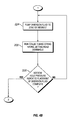
- a technique 100 may generally be performed for purposes of treating the target zones 40.
- a coiled tubing string is deployed in the well, pursuant to block 104.
- the technique 100 involves a repeated loop for purposes of treating the zones 40, one at a time. This may be applicable, for example, where a zone may include one or more clusters of perforations.
- This loop includes treating (block 108) the next zone 40, pursuant to block 108. If a determination is made (diamond 112) that the well 10 contains another zone 40 for treatment, then the technique 100 includes introducing a diversion agent through the coiled tubing string to an interval of the well to facilitate this treatment, pursuant to block 116.
- the target intervals 40 may be treated as follows.
- fluid connectivity is established between the wellbore 12 and the target zones 40 for treatment.
- a target zone for treatment within a subterranean formation is intended to be broadly interpreted as any zone, such as a permeable layer within a stratified formation, a zone within a thick formation that is distinguished by pressure or pressure gradient characteristics more than by stratigraphic or geologic characteristics or a zone that is distinguished by the type or relative cut of fluid (e.g., oil, gas, water) in its pore spaces.
- a vertical wellbore 12 is depicted in Fig. 1
- the techniques that are disclosed herein may be employed advantageously to treat well configurations including, but not limited to, vertical wellbores, fully cased wellbores, horizontal wellbores, open-hole wellbores, wellbores including multiple lateral and wellbores which share more of these characteristics.
- a wellbore may have vertical, deviated, or horizontal portions or combinations thereof.
- the casing string 14 may be cemented in the wellbore, with the method of cementing typically involving pumping cement in the annulus between the casing and the drilled wall of the wellbore.
- the casing string 14 may not be cemented, such as for the case in which casing string 14 lines a lateral wellbore.
- the casing string 14 may be a liner, broadly considered herein as any form of casing that does not extend to the ground surface at the top of the well or even a specific interval length along a horizontal wellbore.
- the target zones 40 of interest for treatment may have differing stress gradients that may inhibit effective treatment of the zones 40, without the use of a diversion agent.
- the target zones 40 may be designated in any number of ways, which can be appreciated by one skilled in the art, such as by open-hole and/or cased-hole logs. As set forth above, the target zones 40 may be perforated using conventional perforation devices for purposes of establishing fluid connectivity between the wellbore 12 and the surrounding formation(s).
- the perforations may be formed in all of the target zones 40 of interest for treatment in a single trip using a perforating gun that is deployed on wireline through the wellbore 12.
- a perforating gun that is deployed on wireline through the wellbore 12.
- fluid connectivity may be established by the use of pre-perforated casing, shifting a sleeve to expose openings between the wellbore and the casing, cutting a slot or slots in the casing or any other such known method to provide an opening between the wellbore 12 and the target zones 40 for treatment.
- Alternative methods such as laser perforating or chemical dissolution are contemplated and are within the scope of the appended claims. It is understood that the benefits of the disclosed methods and compositions may be realized with treatments performed below, at, or above a fracturing pressure of a formation.
- the coiled tubing string 20 is deployed into the wellbore 12 at a desired depth using techniques as can be appreciated by those skilled in the art.
- the acts of establishing fluid connectivity and deploying the coiled tubing string 20 into the wellbore 12 may be combined by deploying a perforating device, such as a jetting sub (part of the BHA), through which an abrasive cutting fluid, or slurry, is pumped downhole via the central passageway of the coiled tubing string 20.
- a perforating device such as a jetting sub (part of the BHA)
- the jetting sub may be used for purposes of cutting through the surrounding casing string 14 and forming perforations into the surrounding formation(s).
- an apparatus or system for measuring or monitoring at least one parameter that is indicative of treatment may then deployed into the wellbore 12.
- the surface treatment monitoring system 64 is connected to the deployed apparatus or system for purposes of monitoring treatment as well as possibly the placement of the diversion agent into the well 10.
- a hydraulic fracturing monitoring system which is capable of detecting and monitoring microseisms in the subterranean formation that results from the hydraulic fracturing may be deployed.
- the surface treatment monitoring system 64 may be coupled to a monitoring device that is deployed inside the coiled tubing string 20.
- a fiber optic-based sensor 50 may be deployed in the coiled tubing string 20, as described in U.S. Patent Application Serial No. 11/111,230 , published as U.S. Patent Application Publication No. 2005/0236161 , which is hereby incorporated by reference in its entirety.
- measurement or monitoring apparatuses suitable for use in the well 10 include, for example, apparatuses known for use in determining borehole parameters such as bottom-hole pressure gauges or bottom-hole temperature gauges.
- apparatuses known for use in determining borehole parameters such as bottom-hole pressure gauges or bottom-hole temperature gauges.
- Another example of systems and methods known for monitoring at least one parameter indicative of treatment is disclosed in U.S. Pat. No. 7,055,604 , which is hereby incorporated by reference in its entirety.
- the measurements which may be monitored include tension or compression acting upon a downhole device (such as coiled tubing) as an indicator of fluid flow friction.
- the measurements may also include downhole measurements of fluid flow rate or velocity.
- treatment of a target zone 40 of interest begins by pumping treatment fluid (via the source 60) into the annulus 16 between the coiled tubing string 20 and the casing string 14 (in the case of a cased well) or between the coiled tubing string 20 and the wellbore wall (in the case of an open hole well).
- the treatment fluid may also be pumped into the wellbore through the coiled tubing.
- the treatment of a target zone 40 by pumping treatment fluid is referred to herein as a treatment stage.
- a treatment fluid may be any suitable treatment fluid known in the art, including, but not limited to, stimulation fluids, water, treated water, aqueous-based fluids, nitrogen, carbon dioxide, any acid (such as hydrochloric, hydrofluoric, acetic acid systems, etc), diesel, or oil-based fluids, gelled oil and water systems, solvents, surfactant systems, and fluids transporting solids for placement adjacent to or into a target zone, for example.
- a treatment fluid may include components such as scale inhibitors in addition to or separately from a stimulation fluid.
- the treatment fluid may include proppant, such as sand, for placement into hydraulic fractures in the target zone by pumping the treatment fluid at high enough pressures to initiate fractures.
- Equipment tanks, pumps, blenders, etc.
- other details for performing treatment stages are known in the art and are not described for simplicity.
- a treatment model appropriate for matrix and/or fracture pressure simulation may be performed to model a planned well treatment in conjunction with the disclosed method.
- Such models are well known in the art with many models being useful for predicting treatment bottom-hole pressures.
- the data generated from such a model may be compared to bottom hole treating pressures (BHTP) during previously described well treatment phase of the disclosed method.
- BHTP bottom hole treating pressures
- At least one parameter of the well which is indicative of the treatment is monitored.
- methods for monitoring a parameter indicative of stimulation are disclosed in U.S. Patent Application No. 11/135,314 , published as U.S Patent Application Publication No. 2005/0263281 , which is hereby incorporated by reference in its entirety.
- Microseisms generated by hydraulic fracturing and other types of treatment may be monitored using hydraulic fracture monitoring (HFM), for example.
- HFM hydraulic fracture monitoring
- the treatment operation may be modified based on the monitored parameter(s) in accordance with some embodiments of the invention.
- a parameter such as microseismic activity may be monitored during hydraulic fracturing to determine or confirm the location and geometric characteristics (e.g. azimuth, height, length, asymmetry) of fractures in the target zone of interest in the subterranean formation; and the pumping schedule may be modified based on the monitored parameter.
- the microseismic activity may be used to determine fracture space within the fractured zone and correlated to a simulated volume of stimulated fracture space within the fractured zone. This simulated volume may be compared to the volume of treatment fluid pumped into target zone of interest, and the comparison repeated over time as the treatment proceeds.
- the simulated volume of void space ceases to increase at a rate analogous to the input volume of treatment fluid, this indicates a decrease in the effectiveness of the treatment.
- the microseismic activity could also be used to determine when the treatment propagates out of zone or into a water producing zone indicating that continued treatment is not beneficial. Based on this monitored parameter and possible comparisons of the monitored parameter with other information, the pumping rate of the treatment fluid may be changed, or stopped and a diversion agent injected.
- the coiled tubing string 20 may be used for precise placement of the diversion agent in the wellbore.
- multiple zones may be controlled based on the monitored parameter(s).
- the design of individual treatment stages may be optimized based on the monitored parameter(s). For example, various treatment parameters, such as pumping schedule, injection rate, fluid viscosity or proppant loading, can be modified during the treatment to provide optimal and efficient treatment of a target zone.
- target zone 40a of Fig. 1 is currently being treated.
- the coiled tubing string 20 is positioned so that the BHA 30 at the end of the coiled tubing string 20 is placed at a location desired for the pumping of a diversion agent into an interval of the wellbore 12 desired for a diversion.
- the location for diversion may be the recently treated zone of interest, which in this example is target zone 40a.
- the diversion of fluid from the wellbore 12 to a subterranean formation or the diversion of a fluid from a subterranean formation to the wellbore is referred to herein as a diversion stage.
- the diversion agent may be pumped in the perforations of the casing string 14 to seal the perforations.
- the diversion agent may be pumped through the perforations and into the stimulated zone in the subterranean formation.
- the diversion agent may be pumped directly from the coiled tubing through the BHA and into the target zone in the subterranean formation.
- the diverting agent could also introduced into the annulus formed between the wellbore wall and coiled tubing.
- the diversion agent is preferable suitable for acting as a diversion agent in the formation or in the perforations.
- the diversion agent may be a fluid that contains fiber.
- the diversion agent may comprise degradable material.
- Known compositions and methods for using slurry comprising a degradable material for diversion are disclosed in U.S. Patent Application No. 11/294,983 , published as U.S. Patent Application Publication No. 2006/0113077 , which is hereby incorporated by reference in its entirety.
- One or more parameters may be monitored in the well 10 to determine or confirm placement of the diversion agent.
- pressure typically increases. So, for example, while pumping the diversion agent, the surface or bottom hole treating pressure may be monitored (via sensors of the BHA 30, for example) for any pressure changes as the diversion agent contacts the formation, as a pressure change may be indicative of placement of the diversion agent.
- the dissolving capacity of a degradable diversion agent when used, preferentially is calibrated to the sequencing of treatment stages to provide diversion from the interval into which is has been placed throughout all the treatment stages.
- a technique 150 may be used to treat multiple target zones of interest.
- fluid connectivity is established between a wellbore and the target zones for treatment, pursuant to block 154.
- a coiled tubing string is deployed (block 158) into the wellbore; and subsequently, a downhole treatment monitoring system is deployed into the wellbore 10, pursuant to block 162.
- a sequence then begins to treat the zones one at a time.
- the treatment of the next target zone begins, pursuant to block 166.
- the treatment is monitored and modified based on one or more monitored downhole parameters, pursuant to block 170.
- the monitoring and modification of treatment continues until it is determined (diamond 174) that the treatment of the current target zone has been completed.
- a determination is made (diamond 178) whether another target zone of interest is to be treated. If so, then a diversion agent is introduced into a particular interval of the well, pursuant to block 182.
- the diversion agent may be introduced into the recently treated zone.
- the treatment and perforation may occur without the use of a coiled tubing string.
- another treatment technique in accordance with embodiments of the invention includes establishing fluid connectivity between a wellbore and target zones for treatment, where the wellbore intersects one or more subterranean formations in which there exists more than one target zone for treatment.
- this technique could be used to stimulate a previously stimulated well.
- the treatment may start by first re-stimulating the existing zones, or by first diverting from the existing zones and then perforating new zones for stimulation.
- the apparatus or system for measuring or monitoring is then deployed into the well, as described above.
- hydraulic fracture monitoring in an offset well may be used or alternatively, an apparatus or system for measuring or monitoring at least one parameter that is indicative of treatment may be deployed in the wellbore.
- the measurement or monitoring device may be deployed with the wellbore, such as the one described in U.S. Patent No. 6,758,271 , and U.S. Patent No. 6,751,556 , each of which is hereby incorporated by reference in its entirety.
- Other measurement or monitoring apparatuses suitable for use in embodiments of the invention include those known for use in determining borehole parameters such as bottom-hole pressure gauges or bottom-hole temperature gauges.
- the treatment of a target zone in the subterranean formation begins by pumping treatment fluid into the wellbore. During this treatment, at least one parameter that is indicative of treatment is monitored and the treatment operation is modified based on the monitored parameter(s).
- a diversion agent is pumped into the wellbore and placed at a location desired for diversion.
- the location for diversion is preferentially the treated target zone of interest.
- the diversion of fluid from the wellbore to a subterranean formation or the diversion of a fluid from a subterranean formation to the wellbore is referred to herein as a diversion stage.
- the diversion agent may be pumped in the perforations in casing to seal the perforations.
- the diversion agent may be pumped through the perforations and into the stimulated zone in the subterranean formation.
- the diversion agent may be placed in the directly into the wellbore.
- the diversion agent is preferable suitable for acting as a diversion agent in the formation or in the perforations.
- the diversion agent may be a fluid comprising fiber.
- the diversion agent may include degradable material.
- the operation to place the diversion agent may then be monitored via the one or more measured parameters to determine or confirm placement of the agent.
- the measured parameter or parameters may be monitored for one or more of the treated target zones or diversion stage throughout the treatment. Such monitoring is useful in the event that a diversion stage loses performance as it would signal the need for an additional diversion stage or re-injection of additional diverting agent in an existing diversion stage.
- pumping of treatment fluid is repeated for more than one target zone.
- pumping of a diversion agent is repeated, with the pumping of treatment fluid and the pumping of diversion agent being staged to permit treatment of a target zone followed by subsequent pumping of the diversion agent into the target zone or the perforations adjacent to the target zone to preclude further flow of treatment fluid into the stimulated target zone.
- the farthest target zone near the toe of the lateral may be stimulated.
- Monitoring of a treatment parameter indicative of treatment is used to determine when the treatment stage in the farthest target zone is complete and then a diversion agent placed in that target zone.
- a treatment stage may be considered to be when the job design has been completed, when additional fracture development is no longer occurring, when the concentration of proppant in a particular interval is becoming greater than desired, or any other indication that additional treatment of that target zone is no longer desired, efficient, or considered to provide additional benefits.
- a treatment stage may then be pumped into the next-farthest target zone with the placed diversion agent diverting the treatment fluid away from the farthest target zone and toward the next-farthest target zone. Monitoring of the treatment parameter indicative of treatment is then used to determine when the treatment stage in the next-farthest target zone is completed.
- a diversion agent is then placed in that next-farthest target zone, thereby diverting the pumped treatment fluid to the next target zone. In this manner, treatment stages may be directed into target zones in a desired sequence, thereby improving the efficiency of the overall treatment by directing the treatment fluid and associated pumping energy into desired intervals.
- the techniques that are described herein may be used to control the desired sequence of individual treatment stages. For example, while typically treatment stages would be performed from the bottom of the well toward the surface, it may be desirable in some situations to treat from top to bottom, or to treat from the top to the bottom within a particular one or ones of the subterranean formations. Alternatively it may also be desirable to treat the zones in order from the lowest stress intervals to the highest stress intervals.
- the diversion agent may be removed by such methods of cleanout, such as injecting a fluid (e.g. nitrogen, water, reactive chemical) into the coiled tubing and jetting the fluid through the BHA 30 to erode or loosen the diversion agent from its diverting position in an interval.
- a fluid e.g. nitrogen, water, reactive chemical
- the fluid in particular a gas, may be pumped down the coiled tubing 20 at a pressure sufficient to offset the formation pressure on the diversion stage, thereby permitting the diversion agent to move from the interval.
- a slowing activating chemical may be placed in the diversion agent to degrade the diversion agent after an estimated period of time.
- a breaker, an encapsulated breaker, or a slow release chemical may be useful in this regard.
- a chemical treatment may be injected into the diversion agent to react with the agent to dissolve, erode, weaken or loosen the diversion agent from its positions.
- a degradable diversion agent may, by its own degrading nature, cease to divert with time. It is preferable that the diversion agent is effectively removable or eliminable from the interval without leaving residue or residual that may hinder the production of hydrocarbons from the target zone.
- a diversion stage in place. For example, when a diversion stage is placed in a water-bearing zone, it may be desired to leave that particular diversion stage in place after stimulation is completed while removing diversion stages located in hydrocarbon bearing zone.
- An advantage of the techniques described herein is that monitoring of a parameter indicative of treatment may provide information as to zones, such as water-bearing zones, for which treatment is not desired. By monitoring the parameter during treatment, the job site operations may be modified to avoid or minimize treatment of undesired zones.
- Embodiments of the invention may include establishing fluid connectivity in a cased wellbore by perforating the casing and if present, the cement in the annulus between the casing and the wellbore wall, using a perforating gun deployed on wireline.
- a perforating gun deployed on wireline a coiled tubing string that has a BHA with a jetting head may be injected using known equipment and methods to a desired depth in the wellbore.
- the casing may be perforated as the coiled tubing is run into the wellbore by pumping fluids at pressure through the coiled tubing and out the jetting head to cut openings in the casing and cement.
- a system for hydraulic fracture monitoring may then deployed and engaged for monitoring.
- StimMAP a mark of Schlumberger
- StimMAP provides methods for monitoring acoustic signals in an offset well or in the same well resulting from microseisms generated in a treatment well by hydraulic fracturing activity.
- Hydraulic fracturing fluid that contains proppant may then pumped at pressure into the wellbore and a target zone of interest is fractured.
- the HFM system is used to monitor the degree and characteristics of the hydraulic fracturing in the target zone of interest in the treatment well. When it is determined using the output of the HFM system that stimulation of the target zone of interest is complete, the hydraulic fracturing operation is modified by stopping or reducing the level of the pressure pumping.
- a diversion fluid that contains degradable fibers, or a diversion fluid comprising degradable fibers and particulates, may then pumped down the coiled tubing to the stimulated target zone of interest.
- Degradable fibers are used in a concentration estimated to provide sufficient structure to permit diversion during hydraulic fracturing activities.
- the composition of the fibers used provides sufficient longevity of the diversion stages to complete hydraulic fracturing fluid while assuring that in a reasonable time period after fracturing, the diversion stages will self-eliminate through degradation of the structure-providing fiber.
- the diversion fluid plugs the fractures created in the target zone of interest.
- the bottom hole treating pressure within the wellbore is monitored to confirm placement of the diversion agent in the target zone of interest.
- Hydraulic fracturing fluid may then again pumped at pressure to fracture another target zone of interest, the fluid being diverted away from the already stimulated target zone of interest by the diversion agent.
- the sequence is repeated for multiple treatment and diversion stages in the wellbore. In this manner, multiple hydrocarbon bearing zones of interest may be stimulated efficiently and production of hydrocarbons may begin from the target zones of interest after stimulation without further intervention to effect stimulated production.
- a technique 200 may be used in accordance with some embodiments of the invention.
- a casing of a well is perforated, pursuant to block 204.
- a coiled tubing string that has a jetting head is run downhole, pursuant to block 208; and a downhole hydraulic fracture monitoring (HFM) system is deployed, pursuant to block 212.
- the treatment of the target zones then begins by pumping (block 216) hydraulic fracturing fluid containing proppant into the well to fracture the next target zone of interest. Based on the HFM system a determination is made (diamond 220) whether fracturing is complete. If not, the pumping continues, pursuant to block 216.
- HFM downhole hydraulic fracture monitoring
- diversion fluid is pumped (block 224 of Fig. 4B ) into the target zone of interest, which was just treated. If a determination is made, pursuant to diamond 228, that the bottom hole pressure indicates completion of the placement of the diversion fluid, then control returns to block 216 for purposes of treating another zone. Otherwise, pumping of the diversion fluid to the recently treated zone of interest continues, pursuant to block 224.
- Stimulation treatment in openhole wells presents challenges in that the uniform removal of damages across the whole section is extremely difficult, if not impossible. Damage in the openhole formation normally occurs in the near wellbore region, due to the drilling of the wellbore. Therefore, the total damaged area to be removed typically is more critical than the depth of the penetration by the stimulation fluid.
- a stimulation treatment that combines a mechanical technique for stimulation and a chemical material for zonal coverage.
- the treatment involves first, the injection of a treatment fluid, such as a "filling fluid" that contains a gel having a suspended fluid loss control agent.
- the filling fluid may be communicated through a jetting tool at a relatively low rate (as compared to the rate used in connection with jetting) to fill up an entire openhole section.
- a solid material such as an abrasive cutting fluid slurry, which contains sand or marble (as examples) is injected into the well by the jetting sub to cut several inches into the formation to bypass the near wellbore damage.
- the fluid leak off into the formation as a result of the cutting is controlled by the fluid loss control agent of the filling fluid.
- the filling fluid does not damage to the formation.
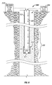
- Fig. 5 depicts a well 300 in accordance with some embodiments of the invention.
- the well 300 includes a wellbore 316 that intersects an exemplary interval 320.
- a coiled tubing string 312 is deployed in the wellbore 316.
- the coiled tubing string 312 includes a bottom hole assembly (BHA), which includes a jetting sub 314. It is noted that the jetting sub 314 may be deployed on a jointed tubing string, in accordance with other embodiments of the invention.
- BHA bottom hole assembly
- the jetting sub 314 may be associated with a reversible check valve, which is activated by deploying a ball 317 through the central passageway of the coiled tubing string 312.
- the ball 317 lodges in a lower port of the coiled tubing string 312 for purposes of directing fluid through radial ports 315 of the jetting tool 314.
- a wellbore filling fluid source 310 communicates the filling fluid (as depicted by flow 340) through the central passageway of the coiled tubing string 312 and via the radial ports 315 into the wellbore interval 320.
- the filling fluid may be made from a gel, made from polymers or VES. Solids or fibrous materials may also be added to the filling material to provide additional leak off control during the subsequent jetting operation.
- the filling fluid is communicated into the wellbore interval 320 prior to the second stage, which is depicted in Fig. 6 .
- the interval 320 is filled by the filling fluid, as depicted at reference numeral 350.
- a cutting fluid source 304 at the surface of the well 300 communicates an abrasive cutting fluid flow, or slurry (as depicted by flow 360), down the central passageway of the coiled tubing string 312 and through the radial ports 315.
- slurry as depicted by flow 360
- the communication of the abrasive slurry occurs at a much higher pressure than the communication of the fill fluid, for purposes of forming the radial jets to penetrate the surrounding formation past any near wellbore damage.
- the abrasive slurry may be neutral or acidic and may contain a low concentration of sand, proppant or other solid materials.
- the filling fluid may be easily removed after the jetting operation or may, alternatively, be self-destructive after the jetting operation, to prevent potential damage to the formation.
- Fig. 7 depicts a combined treatment and jetting technique 400 that may be used in accordance with some embodiments of the invention.
- a gel suspended with a fluid loss control agent is injected (block 404) to fill up a wellbore interval.
- an abrasive slurry is jetted under high pressure to bypass near wellbore damage.
- the invention may be applied to any type of well, for example cased or open hole; drilled with an oil-based mud or a water-based mud; vertical, deviated or horizontal; with or without sand control, such as with a sand control screen.
- sand control such as with a sand control screen.
Claims (37)
- Procédé de traitement de puits, comprenant les étapes consistant à :a) établir un raccordement fluidique entre un forage de puits et au moins une zone cible pour un traitement à l'intérieur d'une formation souterraine croisée par le forage de puits ;b) déployer un tube spiralé dans le forage de puits ;c) introduire une composition de traitement dans le forage de puits ;d) mettre en contact une zone cible à l'intérieur de la formation souterraine avec la composition de traitement ;e) introduire un agent de diversion à travers le tube spiralé jusqu'à un intervalle à l'intérieur du forage de puits et mesurer un paramètre indicatif de diversion dans lequel l'étape consistant à mesurer comprend l'étape consistant à mesurer l'activité micro-sismique ; et
répéter les étapes c) à d) pour plus d'une zone cible. - Procédé selon la revendication 1, dans lequel le forage de puits est tubé et comprenant en outre l'étape consistant à perforer le tubage.
- Procédé selon la revendication 1, dans lequel la composition de traitement comprend un fluide de stimulation.
- Procédé selon la revendication 3, dans lequel l'étape consistant à introduire la composition de traitement comprend l'étape consistant à pomper la composition sous pression.
- Procédé selon la revendication 1, dans lequel au moins une partie du forage de puits comprend une section généralement horizontale.
- Procédé selon la revendication 1, dans lequel l'agent de diversion comprend une fibre.
- Procédé selon la revendication 1, dans lequel l'agent de diversion comprend un matériau dégradable.
- Procédé selon la revendication 1, dans lequel après avoir mis en contact la formation souterraine cible avec la composition de traitement, l'agent de diversion est introduit dans la formation.
- Procédé selon la revendication 1, dans lequel une partie du forage de puits est déviée ou horizontale.
- Procédé selon la revendication 1, comprenant en outre la répétition de l'étape e).
- Procédé selon la revendication 1, comprenant en outre la répétition des étapes a) et b) avant de répéter les étapes c) à d).
- Procédé selon la revendication 1, dans lequel l'agent de diversion est constitué de matériau non-dégradable.
- Procédé selon la revendication 10, dans lequel l'agent de diversion est stocké dans le tube spiralé entre les étapes consistant à introduire l'agent de diversion dans un intervalle.
- Procédé selon la revendication 1, comprenant en outre l'étape consistant à traiter plus d'une zone cible d'intérêt dans la formation souterraine, le procédé comprenant en outre les étapes consistant à :a) pomper la composition de traitement pour mettre en contact l'au moins une zone cible d'intérêt avec la composition de traitement ;b) surveiller le pompage de la composition de traitement et mesurer un paramètre indicatif de traitement ;c) pomper l'agent de diversion jusqu'à un intervalle de diversion souhaité dans le forage de puits ;d) surveiller le pompage de l'agent de diversion et mesurer un paramètre indicatif de diversion dans lequel l'étape consistant à mesurer comprend l'étape consistant à mesurer une activité micro-sismique ;e) pomper la composition de traitement pour mettre en contact au moins une autre zone cible d'intérêt ;f) modifier au moins une des étapes a) et c) en fonction d'au moins un des paramètres mesurés.
- Procédé selon la revendication 14, dans lequel au moins une partie du forage de puits comprend une section généralement déviée ou horizontale.
- Procédé selon la revendication 14, dans lequel au moins un élément parmi l'intervalle de diversion et la zone cible d'intérêt est situé à l'intérieur de ladite section généralement horizontale.
- Procédé selon la revendication 14, comprenant en outre l'étape consistant à répéter les étapes a) à d).
- Procédé selon la revendication 14, comprenant en outre l'étape consistant à injecter la composition de traitement dans l'espace annulaire entre un tube spiralé et le forage de puits.
- Procédé selon la revendication 14, dans lequel l'agent de diversion comprend une fibre.
- Procédé selon la revendication 19, dans lequel la fibre comprend un matériau dégradable.
- Procédé selon la revendication 1, dans lequel le raccordement est établi par un ou plusieurs éléments parmi une perforation, une injection, un manchon coulissant, ou l'ouverture d'une soupape, et dans lequel l'étape consistant à injecter la composition de traitement dans le forage de puits met en contact une formation souterraine de support d'hydrocarbure avec la composition de traitement ;
et le procédé comprenant en outre l'étape consistant à mesurer un paramètre de forage de puits tout en réalisant au moins une étape parmi l'étape b) ou l'étape c), dans lequel l'étape consistant à mesurer comprend l'étape consistant à mesurer une activité micro-sismique. - Procédé selon la revendication 21, dans lequel la composition de traitement comprend un fluide de fracturation et le paramètre de forage de puits mesuré est indicatif d'une fracturation hydraulique dans la formation souterraine.
- Procédé selon la revendication 21, comprenant en outre l'étape consistant à réaliser l'étape consistant au moins à mesurer dans un puits décalé ou surveiller un puits.
- Procédé selon la revendication 21, comprenant en outre l'étape consistant à déterminer une géométrie de fracture hydraulique en fonction au moins en partie de la mesure d'une activité micro-sismique.
- Procédé selon la revendication 21, dans lequel le paramètre de forage de puits mesuré est indicatif de la diversion.
- Procédé selon la revendication 21, comprenant en outre l'étape consistant à modifier au moins une étape parmi l'étape consistant à fournir une diversion et l'étape consistant à injecter une composition de traitement en fonction du paramètre de forage de puits mesuré.
- Procédé selon la revendication 1, comprenant en outre les étapes consistant à :mesurer un paramètre de forage de puits pour établir une ligne de base ; etmesurer le paramètre de forage de puits tout en réalisant au moins une étape parmi l'étape b) et l'étape c),dans lequel l'étape consistant à mesurer comprend l'étape consistant à mesurer une activité micro-sismique.
- Procédé selon la revendication 27, comprenant en outre, avant de réaliser l'étape b), l'étape consistant à établir un raccordement fluidique entre un forage de puits et au moins une zone cible pour un traitement à l'intérieur d'une formation souterraine intersectée par le forage de puits.
- Procédé selon la revendication 27, comprenant en outre l'étape consistant à mesurer le paramètre de forage de puits en continu durant les étapes consistant à fournir l'agent de diversion et à injecter une composition de traitement.
- Procédé selon la revendication 27, comprenant en outre l'étape consistant à modifier le paramètre de forage de puits mesuré à ligne de base en le paramètre de forage de puits mesuré dans l'étape d).
- Procédé selon la revendication 27, comprenant en outre l'étape consistant à modifier le fait que le procédé de traitement est modifié en fonction de la mesure de paramètre de forage de puits de l'étape d).
- Procédé selon la revendication 1, comprenant en outre les étapes consistant à :introduire un agent de diversion à travers un espace annulaire formé entre le forage de puits et le tube spiralé dans un intervalle à l'intérieur du forage de puits et mesurer un paramètre de forage de puits, dans lequel l'étape consistant à mesurer comprend l'étape consistant à mesurer une activité micro-sismique ; etrépéter les étapes c) à e) pour plus d'une zone cible.
- Système utilisable avec un puits, comprenant :une colonne de production ;une source de fluide de traitement pour mettre en communication une composition de traitement dans le puits pour mettre en contact une formation souterraine de support d'hydrocarbure avec la composition de traitement ; etune source d'agent de diversion pour mettre en communication un agent de diversion par l'intermédiaire de la colonne de production dans un intervalle du puits etun équipement micro-sismique pour mesurer un paramètre de forage de puits.
- Système selon la revendication 33, dans lequel la source d'agent de diversion met en communication l'agent de diversion par l'intermédiaire de la colonne de production pour des intervalles supplémentaires du puits.
- Système selon la revendication 33, dans lequel l'agent de diversion isole une région du puits où la composition de traitement est entrée en contact avec la formation.
- Système selon la revendication 33, comprenant en outre :un sous-système de surveillance situé dans le puits pour surveiller au moins un paramètre associé à la communication de la composition de traitement,dans lequel la source de fluide de traitement est commandée en fonction dudit au moins un paramètre.
- Système selon la revendication 33, comprenant en outre :un sous-système de surveillance situé dans le puits pour surveiller au moins un paramètre associé à la communication de l'agent de diversion,dans lequel la source d'agent de diversion est commandée en fonction dudit au moins un paramètre.
Applications Claiming Priority (3)
| Application Number | Priority Date | Filing Date | Title |
|---|---|---|---|
| US80605806P | 2006-06-28 | 2006-06-28 | |
| US11/751,172 US7934556B2 (en) | 2006-06-28 | 2007-05-21 | Method and system for treating a subterranean formation using diversion |
| PCT/IB2007/052478 WO2008001310A1 (fr) | 2006-06-28 | 2007-06-26 | Procédé et système destinés à traiter une formation souterraine à l'aide d'une diversion |
Publications (2)
| Publication Number | Publication Date |
|---|---|
| EP2038512A1 EP2038512A1 (fr) | 2009-03-25 |
| EP2038512B1 true EP2038512B1 (fr) | 2011-10-12 |
Family
ID=38577271
Family Applications (1)
| Application Number | Title | Priority Date | Filing Date |
|---|---|---|---|
| EP07789808A Active EP2038512B1 (fr) | 2006-06-28 | 2007-06-26 | Procédé et système destinés à traiter une formation souterraine à l'aide d'une diversion |
Country Status (7)
| Country | Link |
|---|---|
| US (3) | US7934556B2 (fr) |
| EP (1) | EP2038512B1 (fr) |
| AT (1) | ATE528484T1 (fr) |
| CA (1) | CA2659715C (fr) |
| MX (1) | MX2008016317A (fr) |
| RU (2) | RU2587197C2 (fr) |
| WO (1) | WO2008001310A1 (fr) |
Cited By (2)
| Publication number | Priority date | Publication date | Assignee | Title |
|---|---|---|---|---|
| WO2022031300A1 (fr) * | 2020-08-04 | 2022-02-10 | Halliburton Energy Services, Inc. | Systèmes de complétion, procédés permettant de produire un débit différentiel à travers un orifice pendant différentes opérations de puits et procédés permettant de réduire un reflux d'agent de soutènement |
| WO2023043655A1 (fr) * | 2021-09-15 | 2023-03-23 | Halliburton Energy Services, Inc. | Renforçateur de tensioactif à base d'acide organique pour élimination de contaminants |
Families Citing this family (115)
| Publication number | Priority date | Publication date | Assignee | Title |
|---|---|---|---|---|
| US7934556B2 (en) * | 2006-06-28 | 2011-05-03 | Schlumberger Technology Corporation | Method and system for treating a subterranean formation using diversion |
| US20080196896A1 (en) * | 2007-02-15 | 2008-08-21 | Oscar Bustos | Methods and apparatus for fiber-based diversion |
| US9027668B2 (en) | 2008-08-20 | 2015-05-12 | Foro Energy, Inc. | Control system for high power laser drilling workover and completion unit |
| US9267330B2 (en) | 2008-08-20 | 2016-02-23 | Foro Energy, Inc. | Long distance high power optical laser fiber break detection and continuity monitoring systems and methods |
| US9089928B2 (en) | 2008-08-20 | 2015-07-28 | Foro Energy, Inc. | Laser systems and methods for the removal of structures |
| US9138786B2 (en) | 2008-10-17 | 2015-09-22 | Foro Energy, Inc. | High power laser pipeline tool and methods of use |
| US9360631B2 (en) | 2008-08-20 | 2016-06-07 | Foro Energy, Inc. | Optics assembly for high power laser tools |
| US9719302B2 (en) | 2008-08-20 | 2017-08-01 | Foro Energy, Inc. | High power laser perforating and laser fracturing tools and methods of use |
| US9664012B2 (en) | 2008-08-20 | 2017-05-30 | Foro Energy, Inc. | High power laser decomissioning of multistring and damaged wells |
| US9080425B2 (en) | 2008-10-17 | 2015-07-14 | Foro Energy, Inc. | High power laser photo-conversion assemblies, apparatuses and methods of use |
| US9244235B2 (en) | 2008-10-17 | 2016-01-26 | Foro Energy, Inc. | Systems and assemblies for transferring high power laser energy through a rotating junction |
| US9347271B2 (en) | 2008-10-17 | 2016-05-24 | Foro Energy, Inc. | Optical fiber cable for transmission of high power laser energy over great distances |
| US9669492B2 (en) | 2008-08-20 | 2017-06-06 | Foro Energy, Inc. | High power laser offshore decommissioning tool, system and methods of use |
| US8571368B2 (en) | 2010-07-21 | 2013-10-29 | Foro Energy, Inc. | Optical fiber configurations for transmission of laser energy over great distances |
| US8627901B1 (en) | 2009-10-01 | 2014-01-14 | Foro Energy, Inc. | Laser bottom hole assembly |
| US8636085B2 (en) | 2008-08-20 | 2014-01-28 | Foro Energy, Inc. | Methods and apparatus for removal and control of material in laser drilling of a borehole |
| US9242309B2 (en) | 2012-03-01 | 2016-01-26 | Foro Energy Inc. | Total internal reflection laser tools and methods |
| US10301912B2 (en) * | 2008-08-20 | 2019-05-28 | Foro Energy, Inc. | High power laser flow assurance systems, tools and methods |
| CA2875547C (fr) * | 2008-08-21 | 2016-11-29 | Schlumberger Canada Limited | Agents de soutenement pour fracturation hydraulique |
| CA2770296C (fr) * | 2009-08-05 | 2017-08-01 | Shell Internationale Research Maatschappij B.V. | Systemes et procedes de controle de puits |
| US8534124B2 (en) * | 2009-09-17 | 2013-09-17 | Raytheon Company | Sensor housing apparatus |
| US8286705B2 (en) * | 2009-11-30 | 2012-10-16 | Schlumberger Technology Corporation | Apparatus and method for treating a subterranean formation using diversion |
| WO2011070453A2 (fr) | 2009-12-09 | 2011-06-16 | Schlumberger Canada Limited | Procédé permettant d'augmenter la zone de fracture |
| EP2606201A4 (fr) | 2010-08-17 | 2018-03-07 | Foro Energy Inc. | Systèmes et structures d'acheminement destinés à une émission laser longue distance à haute puissance |
| MX2013007039A (es) * | 2010-12-20 | 2013-12-06 | Schlumberger Technology Bv | Método de utilización de datos de formaciones subterráneas para mejorar las operaciones de tratamiento. |
| WO2012088586A1 (fr) * | 2010-12-27 | 2012-07-05 | Seven Generations Energy Ltd. | Procédés pour forage et stimulation de formations souterraines pour récupérer des ressources d'hydrocarbure et de gaz naturel |
| WO2012116155A1 (fr) | 2011-02-24 | 2012-08-30 | Foro Energy, Inc. | Moteur électrique pour forage laser-mécanique |
| BR112013021478A2 (pt) | 2011-02-24 | 2016-10-11 | Foro Energy Inc | método de perfuração de laser-mecânica de alta potência |
| WO2012167102A1 (fr) | 2011-06-03 | 2012-12-06 | Foro Energy Inc. | Connecteurs optiques robustes à fibre laser d'énergie élevée passivement refroidie et procédés d'utilisation |
| US9222892B2 (en) | 2011-08-05 | 2015-12-29 | Halliburton Energy Services, Inc. | Systems and methods for monitoring the quality of a fluid |
| US9222348B2 (en) | 2011-08-05 | 2015-12-29 | Halliburton Energy Services, Inc. | Methods for monitoring the formation and transport of an acidizing fluid using opticoanalytical devices |
| US9395306B2 (en) | 2011-08-05 | 2016-07-19 | Halliburton Energy Services, Inc. | Methods for monitoring fluids within or produced from a subterranean formation during acidizing operations using opticoanalytical devices |
| US8997860B2 (en) | 2011-08-05 | 2015-04-07 | Halliburton Energy Services, Inc. | Methods for monitoring the formation and transport of a fracturing fluid using opticoanalytical devices |
| US9206386B2 (en) | 2011-08-05 | 2015-12-08 | Halliburton Energy Services, Inc. | Systems and methods for analyzing microbiological substances |
| US8908165B2 (en) | 2011-08-05 | 2014-12-09 | Halliburton Energy Services, Inc. | Systems and methods for monitoring oil/gas separation processes |
| US9182355B2 (en) | 2011-08-05 | 2015-11-10 | Halliburton Energy Services, Inc. | Systems and methods for monitoring a flow path |
| US8960294B2 (en) | 2011-08-05 | 2015-02-24 | Halliburton Energy Services, Inc. | Methods for monitoring fluids within or produced from a subterranean formation during fracturing operations using opticoanalytical devices |
| US9297254B2 (en) | 2011-08-05 | 2016-03-29 | Halliburton Energy Services, Inc. | Methods for monitoring fluids within or produced from a subterranean formation using opticoanalytical devices |
| US9441149B2 (en) | 2011-08-05 | 2016-09-13 | Halliburton Energy Services, Inc. | Methods for monitoring the formation and transport of a treatment fluid using opticoanalytical devices |
| US9261461B2 (en) | 2011-08-05 | 2016-02-16 | Halliburton Energy Services, Inc. | Systems and methods for monitoring oil/gas separation processes |
| US9238953B2 (en) | 2011-11-08 | 2016-01-19 | Schlumberger Technology Corporation | Completion method for stimulation of multiple intervals |
| US8720556B2 (en) * | 2011-11-30 | 2014-05-13 | Halliburton Energy Services, Inc. | Methods for initiating new fractures in a completed wellbore having existing fractures present |
| US8780352B2 (en) | 2012-04-26 | 2014-07-15 | Halliburton Energy Services, Inc. | Methods and devices for optically determining a characteristic of a substance |
| US8823939B2 (en) | 2012-04-26 | 2014-09-02 | Halliburton Energy Services, Inc. | Methods and devices for optically determining a characteristic of a substance |
| US9013702B2 (en) | 2012-04-26 | 2015-04-21 | Halliburton Energy Services, Inc. | Imaging systems for optical computing devices |
| US9019501B2 (en) | 2012-04-26 | 2015-04-28 | Halliburton Energy Services, Inc. | Methods and devices for optically determining a characteristic of a substance |
| US8912477B2 (en) | 2012-04-26 | 2014-12-16 | Halliburton Energy Services, Inc. | Methods and devices for optically determining a characteristic of a substance |
| US8879053B2 (en) | 2012-04-26 | 2014-11-04 | Halliburton Energy Services, Inc. | Devices having an integrated computational element and a proximal interferent monitor and methods for determining a characteristic of a sample therewith |
| US8941046B2 (en) | 2012-04-26 | 2015-01-27 | Halliburton Energy Services, Inc. | Methods and devices for optically determining a characteristic of a substance |
| US9383307B2 (en) | 2012-04-26 | 2016-07-05 | Halliburton Energy Services, Inc. | Methods and devices for optically determining a characteristic of a substance |
| US9658149B2 (en) | 2012-04-26 | 2017-05-23 | Halliburton Energy Services, Inc. | Devices having one or more integrated computational elements and methods for determining a characteristic of a sample by computationally combining signals produced therewith |
| US9013698B2 (en) | 2012-04-26 | 2015-04-21 | Halliburton Energy Services, Inc. | Imaging systems for optical computing devices |
| US9080943B2 (en) | 2012-04-26 | 2015-07-14 | Halliburton Energy Services, Inc. | Methods and devices for optically determining a characteristic of a substance |
| US9702811B2 (en) | 2012-04-26 | 2017-07-11 | Halliburton Energy Services, Inc. | Methods and devices for optically determining a characteristic of a substance using integrated computational elements |
| US9650851B2 (en) | 2012-06-18 | 2017-05-16 | Schlumberger Technology Corporation | Autonomous untethered well object |
| US9175558B2 (en) | 2012-07-31 | 2015-11-03 | Raytheon Company | Seismic navigation |
| US20140054039A1 (en) * | 2012-08-23 | 2014-02-27 | Schlumberger Technology Corporation | Materials and methods to prevent fluid loss in subterranean formations |
| US9103716B2 (en) | 2012-08-31 | 2015-08-11 | Halliburton Energy Services, Inc. | Handheld characteristic analyzer and methods of using the same |
| US9170208B2 (en) | 2012-08-31 | 2015-10-27 | Halliburton Energy Services, Inc. | Handheld characteristic analyzer and methods of using the same |
| US9086383B2 (en) | 2012-09-14 | 2015-07-21 | Halliburton Energy Services, Inc. | Systems and methods for monitoring chemical processes |
| US9176052B2 (en) | 2012-09-14 | 2015-11-03 | Halliburton Energy Services, Inc. | Systems and methods for inspecting and monitoring a pipeline |
| US9222896B2 (en) | 2012-09-14 | 2015-12-29 | Halliburton Energy Services, Inc. | Systems and methods for inspecting and monitoring a pipeline |
| US8765061B2 (en) | 2012-09-14 | 2014-07-01 | Halliburton Energy Services, Inc. | Systems and methods for inspecting and monitoring a pipeline |
| US10240436B2 (en) | 2012-09-20 | 2019-03-26 | Schlumberger Technology Corporation | Method of treating subterranean formation |
| US9702238B2 (en) | 2012-10-25 | 2017-07-11 | Halliburton Energy Services, Inc. | Wellbore servicing methods and compositions comprising degradable polymers |
| US9410076B2 (en) | 2012-10-25 | 2016-08-09 | Halliburton Energy Services, Inc. | Wellbore servicing methods and compositions comprising degradable polymers |
| US8714249B1 (en) | 2012-10-26 | 2014-05-06 | Halliburton Energy Services, Inc. | Wellbore servicing materials and methods of making and using same |
| US9951266B2 (en) | 2012-10-26 | 2018-04-24 | Halliburton Energy Services, Inc. | Expanded wellbore servicing materials and methods of making and using same |
| US10221655B2 (en) | 2012-11-15 | 2019-03-05 | Exxonmobil Upstream Research Company | Wellbore flow-control assemblies for hydrocarbon wells, and systems and methods including the same |
| US9822625B2 (en) | 2013-03-13 | 2017-11-21 | Halliburton Energy Services, Inc. | Methods for treatment of a subterranean formation |
| US20140262231A1 (en) * | 2013-03-13 | 2014-09-18 | Halliburton Energy Services, Inc. | Methods for treatment of a subterranean formation |
| US9097097B2 (en) | 2013-03-20 | 2015-08-04 | Baker Hughes Incorporated | Method of determination of fracture extent |
| EP2818631A1 (fr) * | 2013-06-26 | 2014-12-31 | Welltec A/S | Ensemble de pompage de fond de trou et système de fond de trou |
| EP2994740A4 (fr) | 2013-07-09 | 2016-12-28 | Halliburton Energy Services Inc | Éléments de calcul intégrés ayant des filtres spectraux répartis latéralement |
| AU2013393869B2 (en) | 2013-07-09 | 2017-05-11 | Halliburton Energy Services, Inc. | Integrated computational elements with frequency selective surface |
| US9631468B2 (en) | 2013-09-03 | 2017-04-25 | Schlumberger Technology Corporation | Well treatment |
| US9366124B2 (en) * | 2013-11-27 | 2016-06-14 | Baker Hughes Incorporated | System and method for re-fracturing multizone horizontal wellbores |
| CA2933487C (fr) * | 2014-03-06 | 2018-06-12 | Halliburton Energy Services, Inc. | Derivation de champ lointain avec agent de soutenement pulse dans des operations de fracturation souterraine |
| US9976073B2 (en) | 2014-06-02 | 2018-05-22 | Halliburton Energy Services, Inc. | Methods and systems for controllably generating heat and/or nitrogen gas in subterranean and pipeline operations |
| WO2015191084A1 (fr) | 2014-06-13 | 2015-12-17 | Halliburton Energy Services, Inc. | Élément de calcul intégré à surfaces multiples sélectives en fréquence |
| US9470078B2 (en) * | 2014-09-29 | 2016-10-18 | Baker Hughes Incorporated | Fluid diversion through selective fracture extension |
| US10012069B2 (en) * | 2014-10-31 | 2018-07-03 | Schlumberger Technology Corporation | Method of treatment design and optimization of sequenced fracturing technique |
| US9810051B2 (en) * | 2014-11-20 | 2017-11-07 | Thru Tubing Solutions, Inc. | Well completion |
| US9869170B2 (en) * | 2015-03-17 | 2018-01-16 | Halliburton Energy Services, Inc. | Methods of controlling water production in horizontal wells with multistage fractures |
| US10851615B2 (en) | 2015-04-28 | 2020-12-01 | Thru Tubing Solutions, Inc. | Flow control in subterranean wells |
| US9816341B2 (en) | 2015-04-28 | 2017-11-14 | Thru Tubing Solutions, Inc. | Plugging devices and deployment in subterranean wells |
| US9567826B2 (en) | 2015-04-28 | 2017-02-14 | Thru Tubing Solutions, Inc. | Flow control in subterranean wells |
| US9523267B2 (en) | 2015-04-28 | 2016-12-20 | Thru Tubing Solutions, Inc. | Flow control in subterranean wells |
| US9567824B2 (en) | 2015-04-28 | 2017-02-14 | Thru Tubing Solutions, Inc. | Fibrous barriers and deployment in subterranean wells |
| US9567825B2 (en) | 2015-04-28 | 2017-02-14 | Thru Tubing Solutions, Inc. | Flow control in subterranean wells |
| US9708883B2 (en) | 2015-04-28 | 2017-07-18 | Thru Tubing Solutions, Inc. | Flow control in subterranean wells |
| US10774612B2 (en) | 2015-04-28 | 2020-09-15 | Thru Tubing Solutions, Inc. | Flow control in subterranean wells |
| US10513653B2 (en) | 2015-04-28 | 2019-12-24 | Thru Tubing Solutions, Inc. | Flow control in subterranean wells |
| US11851611B2 (en) | 2015-04-28 | 2023-12-26 | Thru Tubing Solutions, Inc. | Flow control in subterranean wells |
| US9745820B2 (en) | 2015-04-28 | 2017-08-29 | Thru Tubing Solutions, Inc. | Plugging device deployment in subterranean wells |
| US10233719B2 (en) | 2015-04-28 | 2019-03-19 | Thru Tubing Solutions, Inc. | Flow control in subterranean wells |
| US10655427B2 (en) | 2015-04-28 | 2020-05-19 | Thru Tubing Solutions, Inc. | Flow control in subterranean wells |
| US10641069B2 (en) | 2015-04-28 | 2020-05-05 | Thru Tubing Solutions, Inc. | Flow control in subterranean wells |
| US11761295B2 (en) | 2015-07-21 | 2023-09-19 | Thru Tubing Solutions, Inc. | Plugging device deployment |
| WO2017014820A1 (fr) | 2015-07-21 | 2017-01-26 | Thru Tubing Solutions, Inc. | Déploiement de dispositif de colmatage |
| WO2017061993A1 (fr) * | 2015-10-06 | 2017-04-13 | Halliburton Energy Services, Inc. | Systèmes et procédés déduisant le développement d'une fracture hydraulique d'une analyse microsismique |
| US10221687B2 (en) | 2015-11-26 | 2019-03-05 | Merger Mines Corporation | Method of mining using a laser |
| US9920589B2 (en) | 2016-04-06 | 2018-03-20 | Thru Tubing Solutions, Inc. | Methods of completing a well and apparatus therefor |
| US10301903B2 (en) | 2016-05-16 | 2019-05-28 | Schlumberger Technology Corporation | Well treatment |
| US10161235B2 (en) | 2016-06-03 | 2018-12-25 | Enhanced Production, Inc. | Hydraulic fracturing in highly heterogeneous formations by resisting formation and/or sealing micro-fractures |
| WO2018034652A1 (fr) * | 2016-08-16 | 2018-02-22 | Halliburton Energy Services, Inc. | Procédés et systèmes de modélisation d'opérations de traitement par déviation de fluide |
| US10941337B2 (en) | 2016-10-11 | 2021-03-09 | Eastman Chemical Company | Fiber configurations for wellbore treatment compositions |
| US11702931B2 (en) | 2016-11-07 | 2023-07-18 | Halliburton Energy Services, Inc. | Real-time well bashing decision |
| CA3046487C (fr) | 2016-12-13 | 2021-04-20 | Thru Tubing Solutions, Inc. | Procedes de completion d'un puits et appareil associe |
| CN106948795B (zh) * | 2017-03-30 | 2019-09-06 | 中国石油大学(北京) | 一种多分支水平井闭式循环开发水热型地热的方法 |
| WO2018200698A1 (fr) | 2017-04-25 | 2018-11-01 | Thru Tubing Solutions, Inc. | Obturation d'ouvertures indésirables dans des conduits de fluide |
| WO2018200688A1 (fr) | 2017-04-25 | 2018-11-01 | Thru Tubing Solutions, Inc. | Obturation d'ouvertures indésirables dans des récipients de fluide |
| US11352538B2 (en) | 2020-05-29 | 2022-06-07 | Halliburton Energy Services, Inc. | Low molecular mass organic gelator viscosihiers |
| US11603487B2 (en) | 2020-05-29 | 2023-03-14 | Halliburton Energy Services, Inc. | Low molecular mass organic gelator wellbore stabilizers |
| CN117916448A (zh) * | 2021-08-06 | 2024-04-19 | 斯伦贝谢技术有限公司 | 通过优化裂缝导流提高完井的方法 |
Family Cites Families (48)
| Publication number | Priority date | Publication date | Assignee | Title |
|---|---|---|---|---|
| US3998272A (en) | 1975-04-21 | 1976-12-21 | Union Oil Company Of California | Method of acidizing wells |
| US4157116A (en) * | 1978-06-05 | 1979-06-05 | Halliburton Company | Process for reducing fluid flow to and from a zone adjacent a hydrocarbon producing formation |
| SU918918A1 (ru) * | 1980-06-12 | 1982-04-07 | Институт Горного Дела Со Ан Ссср | Способ контрол зоны гидроразрыва горных пород |
| US5258137A (en) | 1984-12-24 | 1993-11-02 | The Dow Chemical Company | Viscoelastic surfactant based foam fluids |
| CA1279469C (fr) | 1987-01-27 | 1991-01-29 | Curtis W. Crowe | Composition et methode de controle de deperdition de fluide en fractionnement acide de couches geologiques |
| US5327973A (en) * | 1992-12-22 | 1994-07-12 | Mobil Oil Corporation | Method for variable density acidizing |
| US5330005A (en) | 1993-04-05 | 1994-07-19 | Dowell Schlumberger Incorporated | Control of particulate flowback in subterranean wells |
| CA2497728C (fr) | 1993-04-05 | 2008-02-19 | Roger J. Card | Regulation du retour des matieres particulaires dans les puits souterrains |
| US5771170A (en) | 1994-02-14 | 1998-06-23 | Atlantic Richfield Company | System and program for locating seismic events during earth fracture propagation |
| US5551516A (en) | 1995-02-17 | 1996-09-03 | Dowell, A Division Of Schlumberger Technology Corporation | Hydraulic fracturing process and compositions |
| US5964295A (en) | 1996-10-09 | 1999-10-12 | Schlumberger Technology Corporation, Dowell Division | Methods and compositions for testing subterranean formations |
| US6435277B1 (en) | 1996-10-09 | 2002-08-20 | Schlumberger Technology Corporation | Compositions containing aqueous viscosifying surfactants and methods for applying such compositions in subterranean formations |
| US6110875A (en) * | 1997-03-07 | 2000-08-29 | Bj Services Company | Methods and materials for degrading xanthan |
| US6258859B1 (en) | 1997-06-10 | 2001-07-10 | Rhodia, Inc. | Viscoelastic surfactant fluids and related methods of use |
| US5924295A (en) | 1997-10-07 | 1999-07-20 | Samsung Electronics Co., Ltd. | Method and apparatus for controlling initial operation of refrigerator |
| US6599863B1 (en) | 1999-02-18 | 2003-07-29 | Schlumberger Technology Corporation | Fracturing process and composition |
| US6399546B1 (en) | 1999-10-15 | 2002-06-04 | Schlumberger Technology Corporation | Fluid system having controllable reversible viscosity |
| US6818594B1 (en) * | 1999-11-12 | 2004-11-16 | M-I L.L.C. | Method for the triggered release of polymer-degrading agents for oil field use |
| US7182138B2 (en) * | 2000-03-02 | 2007-02-27 | Schlumberger Technology Corporation | Reservoir communication by creating a local underbalance and using treatment fluid |
| US7028772B2 (en) | 2000-04-26 | 2006-04-18 | Pinnacle Technologies, Inc. | Treatment well tiltmeter system |
| DZ3387A1 (fr) | 2000-07-18 | 2002-01-24 | Exxonmobil Upstream Res Co | Procede pour traiter les intervalles multiples dans un trou de forage |
| US6938693B2 (en) * | 2001-10-31 | 2005-09-06 | Schlumberger Technology Corporation | Methods for controlling screenouts |
| US6837309B2 (en) | 2001-09-11 | 2005-01-04 | Schlumberger Technology Corporation | Methods and fluid compositions designed to cause tip screenouts |
| AU2002327694A1 (en) | 2001-09-26 | 2003-04-07 | Claude E. Cooke Jr. | Method and materials for hydraulic fracturing of wells |
| US7119050B2 (en) | 2001-12-21 | 2006-10-10 | Schlumberger Technology Corporation | Fluid system having controllable reversible viscosity |
| ITMO20020016A1 (it) * | 2002-01-24 | 2003-07-24 | Sarong Spa | Striscia continua di contenitori |
| US20030234921A1 (en) | 2002-06-21 | 2003-12-25 | Tsutomu Yamate | Method for measuring and calibrating measurements using optical fiber distributed sensor |
| AU2003255294A1 (en) | 2002-08-15 | 2004-03-11 | Sofitech N.V. | Use of distributed temperature sensors during wellbore treatments |
| US6758271B1 (en) | 2002-08-15 | 2004-07-06 | Sensor Highway Limited | System and technique to improve a well stimulation process |
| ATE350428T1 (de) | 2002-10-28 | 2007-01-15 | Schlumberger Technology Bv | Selbstzerst render filterkuchen |
| US20050113263A1 (en) | 2002-10-28 | 2005-05-26 | Brown J. E. | Differential etching in acid fracturing |
| US7115546B2 (en) | 2003-01-31 | 2006-10-03 | Bj Services Company | Acid diverting system containing quaternary amine |
| US7004255B2 (en) | 2003-06-04 | 2006-02-28 | Schlumberger Technology Corporation | Fracture plugging |
| US7032663B2 (en) | 2003-06-27 | 2006-04-25 | Halliburton Energy Services, Inc. | Permeable cement and sand control methods utilizing permeable cement in subterranean well bores |
| US7318475B2 (en) | 2003-11-14 | 2008-01-15 | Schlumberger Technology Corporation | Matrix acidizing high permeability contrast formations |
| US7341107B2 (en) | 2003-12-11 | 2008-03-11 | Schlumberger Technology Corporation | Viscoelastic acid |
| US7503404B2 (en) | 2004-04-14 | 2009-03-17 | Halliburton Energy Services, Inc, | Methods of well stimulation during drilling operations |
| US20050236161A1 (en) | 2004-04-23 | 2005-10-27 | Michael Gay | Optical fiber equipped tubing and methods of making and using |
| US7617873B2 (en) | 2004-05-28 | 2009-11-17 | Schlumberger Technology Corporation | System and methods using fiber optics in coiled tubing |
| US7350572B2 (en) | 2004-09-01 | 2008-04-01 | Schlumberger Technology Corporation | Methods for controlling fluid loss |
| US7380600B2 (en) | 2004-09-01 | 2008-06-03 | Schlumberger Technology Corporation | Degradable material assisted diversion or isolation |
| US7275596B2 (en) | 2005-06-20 | 2007-10-02 | Schlumberger Technology Corporation | Method of using degradable fiber systems for stimulation |
| RU2433157C2 (ru) | 2005-01-21 | 2011-11-10 | Фэйрмаунт Минералз, Лтд. | Отклоняющая жидкость |
| US7353876B2 (en) | 2005-02-01 | 2008-04-08 | Halliburton Energy Services, Inc. | Self-degrading cement compositions and methods of using self-degrading cement compositions in subterranean formations |
| US20070272407A1 (en) * | 2006-05-25 | 2007-11-29 | Halliburton Energy Services, Inc. | Method and system for development of naturally fractured formations |
| US7934556B2 (en) * | 2006-06-28 | 2011-05-03 | Schlumberger Technology Corporation | Method and system for treating a subterranean formation using diversion |
| US7677317B2 (en) * | 2006-12-18 | 2010-03-16 | Conocophillips Company | Liquid carbon dioxide cleaning of wellbores and near-wellbore areas using high precision stimulation |
| US11123005B2 (en) | 2018-11-12 | 2021-09-21 | Medtronic, Inc | Method and apparatus for atrial tachyarrhythmia detection |
-
2007
- 2007-05-21 US US11/751,172 patent/US7934556B2/en active Active
- 2007-06-26 WO PCT/IB2007/052478 patent/WO2008001310A1/fr active Application Filing
- 2007-06-26 AT AT07789808T patent/ATE528484T1/de not_active IP Right Cessation
- 2007-06-26 CA CA2659715A patent/CA2659715C/fr active Active
- 2007-06-26 EP EP07789808A patent/EP2038512B1/fr active Active
- 2007-06-26 RU RU2011120145/03A patent/RU2587197C2/ru active
- 2007-06-26 MX MX2008016317A patent/MX2008016317A/es active IP Right Grant
- 2007-06-26 RU RU2009102650/03A patent/RU2431037C2/ru active
-
2011
- 2011-03-10 US US13/045,146 patent/US8220543B2/en active Active
-
2012
- 2012-07-12 US US13/547,159 patent/US8646529B2/en active Active
Cited By (4)
| Publication number | Priority date | Publication date | Assignee | Title |
|---|---|---|---|---|
| WO2022031300A1 (fr) * | 2020-08-04 | 2022-02-10 | Halliburton Energy Services, Inc. | Systèmes de complétion, procédés permettant de produire un débit différentiel à travers un orifice pendant différentes opérations de puits et procédés permettant de réduire un reflux d'agent de soutènement |
| GB2613961A (en) * | 2020-08-04 | 2023-06-21 | Halliburton Energy Services Inc | Completion systems, methods to produce differential flow rate through a port during different well operations, and methods to reduce proppant flow back |
| WO2023043655A1 (fr) * | 2021-09-15 | 2023-03-23 | Halliburton Energy Services, Inc. | Renforçateur de tensioactif à base d'acide organique pour élimination de contaminants |
| US11820940B2 (en) | 2021-09-15 | 2023-11-21 | Halliburton Energy Services, Inc. | Organic acid surfactant booster for contaminant removal from hydrocarbon-containing stream |
Also Published As
| Publication number | Publication date |
|---|---|
| ATE528484T1 (de) | 2011-10-15 |
| EP2038512A1 (fr) | 2009-03-25 |
| US20080000639A1 (en) | 2008-01-03 |
| RU2009102650A (ru) | 2010-08-10 |
| CA2659715A1 (fr) | 2008-01-03 |
| US8646529B2 (en) | 2014-02-11 |
| US20130168082A1 (en) | 2013-07-04 |
| RU2011120145A (ru) | 2012-11-27 |
| WO2008001310A1 (fr) | 2008-01-03 |
| US7934556B2 (en) | 2011-05-03 |
| RU2587197C2 (ru) | 2016-06-20 |
| MX2008016317A (es) | 2009-01-16 |
| RU2431037C2 (ru) | 2011-10-10 |
| US8220543B2 (en) | 2012-07-17 |
| US20110186298A1 (en) | 2011-08-04 |
| CA2659715C (fr) | 2014-06-17 |
Similar Documents
| Publication | Publication Date | Title |
|---|---|---|
| EP2038512B1 (fr) | Procédé et système destinés à traiter une formation souterraine à l'aide d'une diversion | |
| US8281860B2 (en) | Method and system for treating a subterranean formation | |
| US6394184B2 (en) | Method and apparatus for stimulation of multiple formation intervals | |
| AU2001236978B2 (en) | Method and apparatus for stimulation of multiple formation intervals | |
| US8714244B2 (en) | Stimulation through fracturing while drilling | |
| US7237612B2 (en) | Methods of initiating a fracture tip screenout | |
| US7287592B2 (en) | Limited entry multiple fracture and frac-pack placement in liner completions using liner fracturing tool | |
| US20070284106A1 (en) | Method and apparatus for well drilling and completion | |
| AU2001236978A1 (en) | Method and apparatus for stimulation of multiple formation intervals | |
| EP2659090B1 (fr) | Procédés pour forage et stimulation de formations souterraines pour récupérer des ressources d'hydrocarbure et de gaz naturel | |
| US11346181B2 (en) | Engineered production liner for a hydrocarbon well | |
| Boyd | Completion techniques for geothermal-geopressured wells. Final report |
Legal Events
| Date | Code | Title | Description |
|---|---|---|---|
| PUAI | Public reference made under article 153(3) epc to a published international application that has entered the european phase |
Free format text: ORIGINAL CODE: 0009012 |
|
| 17P | Request for examination filed |
Effective date: 20090128 |
|
| AK | Designated contracting states |
Kind code of ref document: A1 Designated state(s): AT BE BG CH CY CZ DE DK EE ES FI FR GB GR HU IE IS IT LI LT LU LV MC MT NL PL PT RO SE SI SK TR |
|
| AX | Request for extension of the european patent |
Extension state: AL BA HR MK RS |
|
| RIN1 | Information on inventor provided before grant (corrected) |
Inventor name: FREDD, CHRISTOPHER N. Inventor name: BENTLEY, DOUG Inventor name: LASSEK, JOHN Inventor name: DANIELS, JOHN Inventor name: MILLER, CHARLES Inventor name: CLARK, W. E. |
|
| 17Q | First examination report despatched |
Effective date: 20091221 |
|
| GRAP | Despatch of communication of intention to grant a patent |
Free format text: ORIGINAL CODE: EPIDOSNIGR1 |
|
| DAX | Request for extension of the european patent (deleted) | ||
| GRAS | Grant fee paid |
Free format text: ORIGINAL CODE: EPIDOSNIGR3 |
|
| GRAA | (expected) grant |
Free format text: ORIGINAL CODE: 0009210 |
|
| AK | Designated contracting states |
Kind code of ref document: B1 Designated state(s): AT BE BG CH CY CZ DE DK EE ES FI FR GB GR HU IE IS IT LI LT LU LV MC MT NL PL PT RO SE SI SK TR |
|
| REG | Reference to a national code |
Ref country code: GB Ref legal event code: FG4D |
|
| REG | Reference to a national code |
Ref country code: CH Ref legal event code: EP |
|
| REG | Reference to a national code |
Ref country code: IE Ref legal event code: FG4D |
|
| REG | Reference to a national code |
Ref country code: DE Ref legal event code: R096 Ref document number: 602007017826 Country of ref document: DE Effective date: 20120112 |
|
| REG | Reference to a national code |
Ref country code: NL Ref legal event code: VDEP Effective date: 20111012 |
|
| LTIE | Lt: invalidation of european patent or patent extension |
Effective date: 20111012 |
|
| REG | Reference to a national code |
Ref country code: AT Ref legal event code: MK05 Ref document number: 528484 Country of ref document: AT Kind code of ref document: T Effective date: 20111012 |
|
| PG25 | Lapsed in a contracting state [announced via postgrant information from national office to epo] |
Ref country code: LT Free format text: LAPSE BECAUSE OF FAILURE TO SUBMIT A TRANSLATION OF THE DESCRIPTION OR TO PAY THE FEE WITHIN THE PRESCRIBED TIME-LIMIT Effective date: 20111012 Ref country code: BE Free format text: LAPSE BECAUSE OF FAILURE TO SUBMIT A TRANSLATION OF THE DESCRIPTION OR TO PAY THE FEE WITHIN THE PRESCRIBED TIME-LIMIT Effective date: 20111012 Ref country code: IS Free format text: LAPSE BECAUSE OF FAILURE TO SUBMIT A TRANSLATION OF THE DESCRIPTION OR TO PAY THE FEE WITHIN THE PRESCRIBED TIME-LIMIT Effective date: 20120212 |
|
| PG25 | Lapsed in a contracting state [announced via postgrant information from national office to epo] |
Ref country code: NL Free format text: LAPSE BECAUSE OF FAILURE TO SUBMIT A TRANSLATION OF THE DESCRIPTION OR TO PAY THE FEE WITHIN THE PRESCRIBED TIME-LIMIT Effective date: 20111012 Ref country code: GR Free format text: LAPSE BECAUSE OF FAILURE TO SUBMIT A TRANSLATION OF THE DESCRIPTION OR TO PAY THE FEE WITHIN THE PRESCRIBED TIME-LIMIT Effective date: 20120113 Ref country code: SI Free format text: LAPSE BECAUSE OF FAILURE TO SUBMIT A TRANSLATION OF THE DESCRIPTION OR TO PAY THE FEE WITHIN THE PRESCRIBED TIME-LIMIT Effective date: 20111012 Ref country code: LV Free format text: LAPSE BECAUSE OF FAILURE TO SUBMIT A TRANSLATION OF THE DESCRIPTION OR TO PAY THE FEE WITHIN THE PRESCRIBED TIME-LIMIT Effective date: 20111012 Ref country code: SE Free format text: LAPSE BECAUSE OF FAILURE TO SUBMIT A TRANSLATION OF THE DESCRIPTION OR TO PAY THE FEE WITHIN THE PRESCRIBED TIME-LIMIT Effective date: 20111012 Ref country code: PT Free format text: LAPSE BECAUSE OF FAILURE TO SUBMIT A TRANSLATION OF THE DESCRIPTION OR TO PAY THE FEE WITHIN THE PRESCRIBED TIME-LIMIT Effective date: 20120213 |
|
| PG25 | Lapsed in a contracting state [announced via postgrant information from national office to epo] |
Ref country code: CY Free format text: LAPSE BECAUSE OF FAILURE TO SUBMIT A TRANSLATION OF THE DESCRIPTION OR TO PAY THE FEE WITHIN THE PRESCRIBED TIME-LIMIT Effective date: 20111012 |
|
| PG25 | Lapsed in a contracting state [announced via postgrant information from national office to epo] |
Ref country code: EE Free format text: LAPSE BECAUSE OF FAILURE TO SUBMIT A TRANSLATION OF THE DESCRIPTION OR TO PAY THE FEE WITHIN THE PRESCRIBED TIME-LIMIT Effective date: 20111012 Ref country code: DK Free format text: LAPSE BECAUSE OF FAILURE TO SUBMIT A TRANSLATION OF THE DESCRIPTION OR TO PAY THE FEE WITHIN THE PRESCRIBED TIME-LIMIT Effective date: 20111012 Ref country code: SK Free format text: LAPSE BECAUSE OF FAILURE TO SUBMIT A TRANSLATION OF THE DESCRIPTION OR TO PAY THE FEE WITHIN THE PRESCRIBED TIME-LIMIT Effective date: 20111012 Ref country code: BG Free format text: LAPSE BECAUSE OF FAILURE TO SUBMIT A TRANSLATION OF THE DESCRIPTION OR TO PAY THE FEE WITHIN THE PRESCRIBED TIME-LIMIT Effective date: 20120112 Ref country code: CZ Free format text: LAPSE BECAUSE OF FAILURE TO SUBMIT A TRANSLATION OF THE DESCRIPTION OR TO PAY THE FEE WITHIN THE PRESCRIBED TIME-LIMIT Effective date: 20111012 |
|
| PLBE | No opposition filed within time limit |
Free format text: ORIGINAL CODE: 0009261 |
|
| STAA | Information on the status of an ep patent application or granted ep patent |
Free format text: STATUS: NO OPPOSITION FILED WITHIN TIME LIMIT |
|
| PG25 | Lapsed in a contracting state [announced via postgrant information from national office to epo] |
Ref country code: RO Free format text: LAPSE BECAUSE OF FAILURE TO SUBMIT A TRANSLATION OF THE DESCRIPTION OR TO PAY THE FEE WITHIN THE PRESCRIBED TIME-LIMIT Effective date: 20111012 Ref country code: IT Free format text: LAPSE BECAUSE OF FAILURE TO SUBMIT A TRANSLATION OF THE DESCRIPTION OR TO PAY THE FEE WITHIN THE PRESCRIBED TIME-LIMIT Effective date: 20111012 Ref country code: PL Free format text: LAPSE BECAUSE OF FAILURE TO SUBMIT A TRANSLATION OF THE DESCRIPTION OR TO PAY THE FEE WITHIN THE PRESCRIBED TIME-LIMIT Effective date: 20111012 |
|
| 26N | No opposition filed |
Effective date: 20120713 |
|
| REG | Reference to a national code |
Ref country code: DE Ref legal event code: R097 Ref document number: 602007017826 Country of ref document: DE Effective date: 20120713 |
|
| PG25 | Lapsed in a contracting state [announced via postgrant information from national office to epo] |
Ref country code: MC Free format text: LAPSE BECAUSE OF NON-PAYMENT OF DUE FEES Effective date: 20120630 Ref country code: AT Free format text: LAPSE BECAUSE OF FAILURE TO SUBMIT A TRANSLATION OF THE DESCRIPTION OR TO PAY THE FEE WITHIN THE PRESCRIBED TIME-LIMIT Effective date: 20111012 |
|
| REG | Reference to a national code |
Ref country code: CH Ref legal event code: PL |
|
| REG | Reference to a national code |
Ref country code: CH Ref legal event code: PL |
|
| REG | Reference to a national code |
Ref country code: IE Ref legal event code: MM4A |
|
| REG | Reference to a national code |
Ref country code: FR Ref legal event code: ST Effective date: 20130228 |
|
| PG25 | Lapsed in a contracting state [announced via postgrant information from national office to epo] |
Ref country code: ES Free format text: LAPSE BECAUSE OF FAILURE TO SUBMIT A TRANSLATION OF THE DESCRIPTION OR TO PAY THE FEE WITHIN THE PRESCRIBED TIME-LIMIT Effective date: 20120123 Ref country code: FR Free format text: LAPSE BECAUSE OF NON-PAYMENT OF DUE FEES Effective date: 20120702 Ref country code: CH Free format text: LAPSE BECAUSE OF NON-PAYMENT OF DUE FEES Effective date: 20120630 Ref country code: LI Free format text: LAPSE BECAUSE OF NON-PAYMENT OF DUE FEES Effective date: 20120630 Ref country code: IE Free format text: LAPSE BECAUSE OF NON-PAYMENT OF DUE FEES Effective date: 20120626 |
|
| PG25 | Lapsed in a contracting state [announced via postgrant information from national office to epo] |
Ref country code: FI Free format text: LAPSE BECAUSE OF FAILURE TO SUBMIT A TRANSLATION OF THE DESCRIPTION OR TO PAY THE FEE WITHIN THE PRESCRIBED TIME-LIMIT Effective date: 20111012 |
|
| PG25 | Lapsed in a contracting state [announced via postgrant information from national office to epo] |
Ref country code: MT Free format text: LAPSE BECAUSE OF FAILURE TO SUBMIT A TRANSLATION OF THE DESCRIPTION OR TO PAY THE FEE WITHIN THE PRESCRIBED TIME-LIMIT Effective date: 20111012 |
|
| PG25 | Lapsed in a contracting state [announced via postgrant information from national office to epo] |
Ref country code: TR Free format text: LAPSE BECAUSE OF FAILURE TO SUBMIT A TRANSLATION OF THE DESCRIPTION OR TO PAY THE FEE WITHIN THE PRESCRIBED TIME-LIMIT Effective date: 20111012 |
|
| PG25 | Lapsed in a contracting state [announced via postgrant information from national office to epo] |
Ref country code: LU Free format text: LAPSE BECAUSE OF NON-PAYMENT OF DUE FEES Effective date: 20120626 |
|
| PG25 | Lapsed in a contracting state [announced via postgrant information from national office to epo] |
Ref country code: HU Free format text: LAPSE BECAUSE OF FAILURE TO SUBMIT A TRANSLATION OF THE DESCRIPTION OR TO PAY THE FEE WITHIN THE PRESCRIBED TIME-LIMIT Effective date: 20070626 |
|
| PGFP | Annual fee paid to national office [announced via postgrant information from national office to epo] |
Ref country code: DE Payment date: 20190612 Year of fee payment: 13 |
|
| REG | Reference to a national code |
Ref country code: DE Ref legal event code: R119 Ref document number: 602007017826 Country of ref document: DE |
|
| PG25 | Lapsed in a contracting state [announced via postgrant information from national office to epo] |
Ref country code: DE Free format text: LAPSE BECAUSE OF NON-PAYMENT OF DUE FEES Effective date: 20210101 |
|
| PGFP | Annual fee paid to national office [announced via postgrant information from national office to epo] |
Ref country code: GB Payment date: 20230504 Year of fee payment: 17 |