EP2038128B1 - Writing instrument with cushioning device - Google Patents
Writing instrument with cushioning device Download PDFInfo
- Publication number
- EP2038128B1 EP2038128B1 EP06820967.5A EP06820967A EP2038128B1 EP 2038128 B1 EP2038128 B1 EP 2038128B1 EP 06820967 A EP06820967 A EP 06820967A EP 2038128 B1 EP2038128 B1 EP 2038128B1
- Authority
- EP
- European Patent Office
- Prior art keywords
- spring member
- barrel
- tubular part
- writing instrument
- central axis
- Prior art date
- Legal status (The legal status is an assumption and is not a legal conclusion. Google has not performed a legal analysis and makes no representation as to the accuracy of the status listed.)
- Not-in-force
Links
Images



Classifications
-
- B—PERFORMING OPERATIONS; TRANSPORTING
- B43—WRITING OR DRAWING IMPLEMENTS; BUREAU ACCESSORIES
- B43K—IMPLEMENTS FOR WRITING OR DRAWING
- B43K24/00—Mechanisms for selecting, projecting, retracting or locking writing units
- B43K24/02—Mechanisms for selecting, projecting, retracting or locking writing units for locking a single writing unit in only fully projected or retracted positions
- B43K24/08—Mechanisms for selecting, projecting, retracting or locking writing units for locking a single writing unit in only fully projected or retracted positions operated by push-buttons
- B43K24/084—Mechanisms for selecting, projecting, retracting or locking writing units for locking a single writing unit in only fully projected or retracted positions operated by push-buttons with saw-like or analogous cams
-
- B—PERFORMING OPERATIONS; TRANSPORTING
- B43—WRITING OR DRAWING IMPLEMENTS; BUREAU ACCESSORIES
- B43K—IMPLEMENTS FOR WRITING OR DRAWING
- B43K17/00—Continuously-adjustable nibs, e.g. for drawing-pens; Holders therefor
- B43K17/005—Continuously-adjustable nibs, e.g. for drawing-pens; Holders therefor continuously-adjustable nibs
Definitions
- the present invention relates to a writing instrument with a retractable writing tip and a cushioning device enabling retractation of the writing tip when an excessive pressure is exerted thereon by a user. More particularly, the present invention relates to a writing instrument according the preamble of the claim 1.
- a cushioning device improves the writing comfort for the user and could avoid damages to the paper sheet or to the writing tip. It could be used for various kinds of writing instruments, and notably for ballpoint pens, fibrous pens or mechanical pencils. In the particular case of a mechanical pencil, the cushioning device reduces the risk of breaking the lead when the user exercises a high pressure on the paper sheet.
- Various embodiments of a cushioning device are known, for example from the document US-A-2004/0234322 .
- the writing instruments on the market having a cushioning device belong to the type of non-retractable writing instruments, i.e. instruments in which the writing tip cannot be retracted within the barrel when not in use.
- a writing instrument including an actuating mechanism and a cushioning device in the rear portion of the barrel is known from the patent document US-A-3272541 published in 1966 .
- the portion of the barrel disclosed includes many sleeves for enclosing two helical springs.
- a plunger spring 38 allows a plunger 35 to be reciprocable in the housing by means of a push button 39.
- a cushioning spring 46 makes the cartridge to yield resiliently via a tubular detent member 26 when the writing tip is pressed against a writing surface.
- a detent adjusting member 27 is axially adjustable by turning the push button 39, to alter compression of the cushioning spring 46 for readily adjusting the resiliency of the writing tip to a selected degree of firmness.
- GB-A-2130530 discloses a resilient element having a tubular shape with transverse notches in staggered arrangement.
- the provision of the spring member integrally formed with a part of the actuating mechanism reduce the number of parts of the writing instrument. That reduces the cost and mostly facilitates the assembly of the mechanism with the cushioning device.
- These provisions also save space within the barrel for the ink cartridge since the spring member is located near the rear end of the barrel, is immediately adjacent to the actuating mechanism, and defines a through hole in which some parts of the mechanism are arranged.
- the spring member is designed to prevent transmission of torque around said central axis to said movable part of the actuation mechanism when said spring member is compressed in the direction of said central axis.
- a spring member having a helical shape a little rotation of one end could occur when that type of spring member is compressed. This has no real drawback with non-retractable writing instruments such as described in US-A-2004/0234322 .
- the retractable instrument comprising parts guided precisely along a longitudinal direction by cooperation of grooves and ribs, it has been found that frictional forces could appear between the mechanism and the barrel, if the spring member creates a torque.
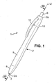
- FIG. 1 shows a preferred embodiment of a writing instrument according to the invention.
- the instrument 1 has a barrel 2 extending along a central axis Z from a front end 2a to rear end 2b.
- the front end 2a has a front aperture 3 through which a writing tip 4 is movable between an extended position represented on figure 3 , and a retracted position represented in figure 4 .
- the rear end 2b of the barrel has a rear aperture 5 through which extends a rear knock button 6.
- the barrel 2 comprises, from the front to the rear ends, a nose-cone 8, an intermediate tubular member 9 and a rear tubular member 10 having a clip 11.
- the barrel can be constituted by a different number of parts.
- the writing tip 4 is a ballpoint tip formed at a front end of an ink cartridge 14 visible in figure 2 .
- the ink cartridge 14 has two opposite projections 14a.
- the invention is not limited to that kind of writing tip and could be used, for example, with a mechanical pencil cartridge having an integrated lead advance mechanism, or with a fibrous writing tip if the writing instrument is provided with a removable cap or a device for sealing the front aperture 3 in retracted position.
- a biasing member 16 is arranged between the front end 2a and projections 14a of the ink cartridge 14 to elastically bias the cartridge toward the rear end 2b.
- An actuation mechanism 20 and a cushioning device 30 are also provided within the barrel 2.
- the actuation mechanism 20 enables the writing tip 4 to extend or retract when a user activates an actuation member formed by the rear knock button 6 in the represented embodiment.
- the function of the cushioning device 30 is to absorb an excessive pressure exerted on the writing tip 4 by the user.
- the cushioning device must enable a little rearward displacement of the writing tip if the pressure exerted thereon is excessive. Generally, when the writing tip 4 moves rearward towards the retracted position the user releases the pressure exerted on the writing instrument. Then, the resiliency of the cushioning device 30 enables the return of the writing tip 4 to the extended position.
- the actuating mechanism is of the ratchet-plunger type which is known per se, in particular from document US-A-4 991 988 .
- This mechanism comprises a ratchet 21, a plunger 22, a tubular part 23 and an adaptor 24.
- the tubular part 23 has an annular internal surface provided with a saw-like cam path 25.
- the cam path 25 forms front and rear abutment portions (25a, 25b) separated by six longitudinal grooves 26, as best shown on figure 7 .
- the plunger 22 has a stem portion 22a extending toward the rear and six radial projections 27 adjacent to the front end 22a which slidingly engage the grooves 26 of the tubular part 23.
- the front end 22a of the plunger 22 has the shape of a teethed crown.
- the ratchet 21 has a cylindrical projection 21b rotatively inserted through the front end 22a of the plunger 22.
- the ratchet 21 has also an annular shoulder 28 presenting a surface oriented toward the rear end 2b which is complementary to the teethed crown 22a of the plunger.
- Three longitudinal projections 29 are provided on the external surface of the ratchet 21 from the shoulder 28 to the front end 21a. The rear end of the longitudinal projections 29 can abut against either the front or the rear portion 25a, 25b of the cam path 25, and can be guided longitudinally by the grooves 26.
- the adaptor 24 has a rear pin portion 24b inserted within the ratchet 21, and a front cup-shaped portion 24a against which the ink cartridge 14 abuts upon the action of the biasing member 16.
- the adaptor 24 may have conical shape with a flat end at it front end.
- the adaptor 24 may be mounted free to rotate in the ratchet 21 to avoid the transmission of a rotational displacement or torque between the ratchet 21 and the ink cartridge 14.
- the adaptor 24 could be fixed to the ratchet 21, and even fitted over the cartridge 14 in a manner that prevents relative rotation between them, without impeding the operation of the ratchet-plunger mechanism 20.
- the plunger 22 moves forward relative to the tubular part 23 and cooperates with the ratchet 21 to push the longitudinal projections 29 out the grooves 26 of the tubular part 23.
- the teethed crown 22a of the plunger 22 and the complementary shoulder 28 of the ratchet 21 are designed to create a slight rotation of the ratchet 21 when the rear knock button is pressed forward. Consequently, the longitudinal projection 29 of the ratchet abut alternatively against the front and the rear portions 25a, 25b of the cam path of the tubular part 23 when the user releases the rear knock button 6.
- This actuation mechanism 20 causes the movement of the writing tip 4 from the retracted position to the extended position, and reversely, upon each actuation of the rear knock button 6.
- the ratchet-plunger type mechanism is convenient for most users and requires little space.
- the external diameter of the ratchet and the plunger can be small in comparison of the barrel's diameter. Consequently, it saves enough space for accommodating the sliding tubular part 23.
- the tubular part 23 has an external surface 23c which is designed for enabling a longitudinal displacement relative to the barrel 2.
- Two opposite projections 31 are provided on the external surface 23c and cooperate with longitudinal grooves of the barrel, not shown, for preventing rotation of the tubular part 23 relative to the barrel 2.
- the projections 31 of the tubular member 23 and the adaptor 24 avoid transmission of a torque to the ratchet 21. Consequently, this prevents a rotation the ratchet 21 without actuating the rear knock button 6 and then avoids an involuntary change of position of the writing tip 4.
- the mobility of the tubular part 23 must enable a displacement thereof from the position corresponding to the extended position of the writing tip represented in doted line, towards the rear end 2b of the barrel along a predetermined longitudinal distance d .
- This predetermined distance d must be long enough to obtain the cushioning effect when the writing tip moves rearward from an excessive pressure.
- the longitudinal position of the tubular part 23 is the same for the retracted and extended positions of the writing tip 4. This simplifies the cushioning device 30 and facilitates the adjusting of the cushioning force.
- the rear end 23b of the tubular part 23 is provided with a spring member 32 which extends towards the rear end 2b of the barrel 2.
- the spring member 32 has a free end 32b opposite to the tubular member 23 which abuts in the rear direction against an internal shoulder 33 of the barrel 2.
- the spring member 32 is resiliently compressible in the direction of the central axis Z for enabling a rearward displacement of the whole actuating mechanism 20 and consequently of the writing tip 4.
- the spring member 32 is integrally formed with the tubular part 23 during an injection molding process of plastic material. This enables the manufacturing of a single piece having two functions during the same step.
- the spring member 32 has a through hole 35 which is collinear to the central axis Z and approximatively of the same diameter as the internal diameter of the tubular part 23.
- the through hole 35 provides a passage for connecting the rear knock button 6 forming the actuation member of the mechanism and the ratchet-plunger mechanism 20 itself.
- the long tubular piece (23, 32) constituted by the tubular part 23 and the spring member 32, the plunger 22, the ratchet 21 and the pin 24 form a first sub-assembly easy to manipulate if the spring member 32 is oriented downward.
- This first sub-assembly can be inserted in the rear tubular member 10 of the barrel with the rear end 2b thereof oriented downward. Then, the rear knock button 6 is inserted through the rear aperture 5 of the barrel and is snap fitted on the stem 22b of the plunger 22.
- the rear knock button 6, the plunger 22, the single tubular piece (23, 32) and the rear tubular member 10 form a non-separable second sub-assembly which can be manipulated in any direction and in particular with the knock button 6 oriented upward to snap fitted on a third sub-assembly comprising the nose-cone 8, the intermediate tubular member 9, the biasing member 16 and the ink cartridge 14 with the nose-cone oriented downward.
- an annular bead 34 extends radially from the interior surface of the tubular member 23 at its front end 23a. Otherwise, the adaptor 24 has a small projection 36 at the rear side of the tubular cylindrical part 24a, as visible on figure 2 .
- the spring member 32 has a particular shape which is designed to not transmit any rotational displacement or torque about the central axis Z, when it is compressed axially, to the tubular part 23 integrally formed with it. Indeed, a torque or rotational displacement created by the spring member 32, could be detrimental for the cushioning function if a frictional force is induced between the tubular part 23 and the barrel 2, or detrimental for the functioning of the ratchet-plunger mechanism if an unexpected angular displacement appears between the ratchet 21 and the cam path 25.
- the spring member comprises a first and a second wavy portion (37, 38) extending globally in direction of the central axis Z from the rear end 23b of the tubular part 23 to a ring 39 forming the rear end 32b of the spring member 32.
- These portions (37, 38) have a shape similar to a band forming waves on both side of its main extension axis like sinusoidal curve along an abscise axis. Consequently, the wavy portions (37, 38) present firsts and seconds curves (37a, 38a;37b, 38b) on the both sides of their extension axis which are parallel to the central axis Z.
- each of the wavy portions does not have to correspond to sinusoidal curves; some variations of the amplitude around the extension axis, the radius of the curves and the circumferential extension angle of the curves are possible. This wavy shape avoids creating a torque or an angular displacement around the central axis Z when the spring member is compressed 32.
- each of the wavy portions has an odd number of the firsts and seconds curves (37a, 37b; 38a, 38b) equally distributed on both side of the extension axis, and for example four curves in the preferred embodiment.
- the wavy portions (37, 38) have also the advantage to provide a high resiliency over a significative distance, even if the spring rate thereof is not constant.
- the continuously curved shape of the wavy portions (37, 38) prevent concentration of mechanical stress in some areas thereof, which would be the case with a spring member having sharp edges. This feature provides important advantages. In deed, it enhances the elastic return of the wavy portions to their initial shape, and also increases their service life.
- the first and second wavy portions (37, 38) are arranged in diametrical opposite direction relatively to the central axis Z and arcuated toward this axis to define the through hole 35 extending through the spring member 32.
- the spring member 32 may comprise more than two wavy portions or only one wavy portion, eventually with additional portions having a different shape, to obtain the same advantages.
- the first and the second wavy portion are linked together by a junction points 32c situated at the middle section of two adjacent curves (37b, 38a) of the first and second wavy portion (37, 38) respectively.
- This feature reinforces the tubular shape of the spring member 32 and can prevent damages to the wavy portions which have a small cross sectional area, for example during the manufacturing process.
- the ring 39 at the free end 23b of the spring member also reinforces the tubular structure of the spring member 23.
- the cushioning device 30 further comprises an additional spring member 41.
- This additional spring member 41 is an helical spring made of metal which is arranged between an external shoulder 23d oriented rearwardly of the tubular part 23 and an internal shoulder 44 oriented forwardly of the barrel 2.
- the additional spring member 41 is compressed in the direction of the longitudinal axis 2 when an excessive pressure is exerted on the writing tip 4. Consequently, the additional spring member 41 creates a cushioning force together with the spring member 32.
- the provision of two spring members could be advantageous to adapt the cushioning force of the whole cushioning device 30.
- the spring member 32 made of plastic material may have a spring rate which is not constant or not high enough for the cushioning function.
- the additional spring 41 increases the spring rate of the cushioning device 30 and could increase the initial force from which the writing tip 4 retracts, if this additional spring 41 is pre-stressed between the tubular parts 23 on the barrel 2. So, the provision of two different spring members having different spring rate characteristics allows to adjust the spring rate characteristics of the whole cushioning device 30, i.e. the cushioning force according to the rearward displacement of the writing tip, to obtain a particularly efficient cushioning function.
- the cushioning force could be set as to increase none linearly, but faster and faster as writing tip moves rearward.
- the additional spring 41 is arranged around the rear portion for the tubular part 23.
- the front end of the spring 41 is slightly press fitted on small protrusions 23e situated near the shoulder 23d of the tubular part.
- the additional spring member 41 is retained on the tubular part 23 and forms a part of the first sub-assembly. Therefore, the additional spring member is not detrimental for the assembly operations of the writing instrument. It should be noted that the frictional force between the additional spring 41 and the barrel is low because it is a metal/plastic contact and only a fraction of the writing pressure is exerted at this point of contact. Consequently, the additional spring 41 cannot create a significative torque.
Landscapes
- Mechanical Pencils And Projecting And Retracting Systems Therefor, And Multi-System Writing Instruments (AREA)
Description
- The present invention relates to a writing instrument with a retractable writing tip and a cushioning device enabling retractation of the writing tip when an excessive pressure is exerted thereon by a user. More particularly, the present invention relates to a writing instrument according the preamble of the
claim 1. - The use of a cushioning device improves the writing comfort for the user and could avoid damages to the paper sheet or to the writing tip. It could be used for various kinds of writing instruments, and notably for ballpoint pens, fibrous pens or mechanical pencils. In the particular case of a mechanical pencil, the cushioning device reduces the risk of breaking the lead when the user exercises a high pressure on the paper sheet. Various embodiments of a cushioning device are known, for example from the document
US-A-2004/0234322 . However, the writing instruments on the market having a cushioning device belong to the type of non-retractable writing instruments, i.e. instruments in which the writing tip cannot be retracted within the barrel when not in use. Thus, most of these instruments are provided with a removable cap to be fitted on the front end of the barrel in order to avoid the marking of stains and/or the drying-out of the tip. In fact, the provision of an actuating mechanism for retracting/extending the tip together with a cushioning device within the barrel raise some issues. - One raised issue is the complexity of such a writing instrument which increases considerably the manufacturing process and the cost. There is also an tissue about the remaining space within the barrel for receiving an ink cartridge, mostly if the lifetime of the writing instrument should not be reduced excessively.
- A writing instrument including an actuating mechanism and a cushioning device in the rear portion of the barrel is known from the patent document
US-A-3272541 published in 1966 . The portion of the barrel disclosed includes many sleeves for enclosing two helical springs. Aplunger spring 38 allows aplunger 35 to be reciprocable in the housing by means of apush button 39. A cushioning spring 46 makes the cartridge to yield resiliently via a tubulardetent member 26 when the writing tip is pressed against a writing surface. A detent adjustingmember 27 is axially adjustable by turning thepush button 39, to alter compression of the cushioning spring 46 for readily adjusting the resiliency of the writing tip to a selected degree of firmness. -
GB-A-2130530 - Thus, there remains a need for retractable tip writing instrument with a cushioning device that can be produced in industrial quantities at an acceptable price.
- According the invention the writing has the features of the
claim 1. - The provision of the spring member integrally formed with a part of the actuating mechanism reduce the number of parts of the writing instrument. That reduces the cost and mostly facilitates the assembly of the mechanism with the cushioning device. These provisions also save space within the barrel for the ink cartridge since the spring member is located near the rear end of the barrel, is immediately adjacent to the actuating mechanism, and defines a through hole in which some parts of the mechanism are arranged.
- According to another aspect the spring member is designed to prevent transmission of torque around said central axis to said movable part of the actuation mechanism when said spring member is compressed in the direction of said central axis. In fact, with a spring member having a helical shape, a little rotation of one end could occur when that type of spring member is compressed. This has no real drawback with non-retractable writing instruments such as described in
US-A-2004/0234322 . However, with the retractable instrument comprising parts guided precisely along a longitudinal direction by cooperation of grooves and ribs, it has been found that frictional forces could appear between the mechanism and the barrel, if the spring member creates a torque. - Various embodiments of a spring member which does not transmit any torque could be designed. However, preferred embodiments of the invention have one or more of the following features:
- the wavy portion has an odd number of curves regularly distributed on both sides of its extension axis;
- at least a first and a second wavy portion are provided, said first and second wavy portion being circumferentially arcuated around said central axis to at least partially define said through hole of the spring member;
- the first and second wavy portion are linked together by the middle section of two adjacent curves belonging respectively to said first and second wavy portion;
- the at least one wavy portion is terminated by a ring at the free end side of the spring member.
- Various types of actuating mechanism are suitable for being combined with the cushioning device according to the invention, however the following features can be provided in preferred embodiments:
- the movable part integrally formed with said spring member is tubular and has a central axis collinear with the through hole of said spring member;
- the cushioning device further comprises an additional spring member formed by a metallic helical spring provided between said movable part of the mechanism and said barrel;
- the spring rate characteristics of said additional helical spring are different of the spring rate characteristics of said spring member;
- the additional helical spring is fitted on said movable part of the actuating mechanism;
- the movable part has at least one cam path cooperating with a rotative part of the actuation mechanism;
- the actuating mechanism is a ratchet-plunger type mechanism actuated by a rear knock button.
- Other features and advantages of the invention will become apparent in view of the following description of a preferred embodiment, which is given by way of non limitating example, with reference to the appended drawings, in which:
-
figure 1 is a perspective view of a retractable instrument comprising an actuation mechanism and a cushioning device according to the invention; -
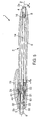
figure 2 is an exploded view of the writing instrument offigure 1 ; -
figure 3 is a cross-sectional view of the writing instrument offigure 1 along line III-III with a writing tip in an extended position; -
figure 4 is a view analogue tofigure 3 in which the writing tip is in a retracted position; -
figure 5 is a view analogue tofigure 3 in which the writing tip is in a cushioned position; -
figures 6a, 6b and 6c are right, front and left views respectively of a part belonging to the actuation mechanism and to the cushioning device; and -
figure 7 is a cross-sectional view of the part offigure 6b along line VII-VII. - The same numeral references are used in the various figures to designate identical or similar components.
-
Figure 1 shows a preferred embodiment of a writing instrument according to the invention. Theinstrument 1 has abarrel 2 extending along a central axis Z from afront end 2a torear end 2b. Thefront end 2a has afront aperture 3 through which awriting tip 4 is movable between an extended position represented onfigure 3 , and a retracted position represented infigure 4 . Therear end 2b of the barrel has a rear aperture 5 through which extends arear knock button 6. - The
barrel 2 comprises, from the front to the rear ends, a nose-cone 8, an intermediatetubular member 9 and a reartubular member 10 having aclip 11. However, the barrel can be constituted by a different number of parts. - The
writing tip 4 is a ballpoint tip formed at a front end of anink cartridge 14 visible infigure 2 . Theink cartridge 14 has twoopposite projections 14a. However, the invention is not limited to that kind of writing tip and could be used, for example, with a mechanical pencil cartridge having an integrated lead advance mechanism, or with a fibrous writing tip if the writing instrument is provided with a removable cap or a device for sealing thefront aperture 3 in retracted position. - With reference to
figures 2 to 5 , abiasing member 16 is arranged between thefront end 2a andprojections 14a of theink cartridge 14 to elastically bias the cartridge toward therear end 2b. - An
actuation mechanism 20 and acushioning device 30 are also provided within thebarrel 2. Theactuation mechanism 20 enables thewriting tip 4 to extend or retract when a user activates an actuation member formed by therear knock button 6 in the represented embodiment. The function of thecushioning device 30 is to absorb an excessive pressure exerted on thewriting tip 4 by the user. The cushioning device must enable a little rearward displacement of the writing tip if the pressure exerted thereon is excessive. Generally, when thewriting tip 4 moves rearward towards the retracted position the user releases the pressure exerted on the writing instrument. Then, the resiliency of thecushioning device 30 enables the return of thewriting tip 4 to the extended position. - The actuating mechanism is of the ratchet-plunger type which is known per se, in particular from document
US-A-4 991 988 . This mechanism comprises aratchet 21, aplunger 22, atubular part 23 and anadaptor 24. - The
tubular part 23 has an annular internal surface provided with a saw-like cam path 25. Thecam path 25 forms front and rear abutment portions (25a, 25b) separated by sixlongitudinal grooves 26, as best shown onfigure 7 . - The
plunger 22 has astem portion 22a extending toward the rear and sixradial projections 27 adjacent to thefront end 22a which slidingly engage thegrooves 26 of thetubular part 23. Thefront end 22a of theplunger 22 has the shape of a teethed crown. - The
ratchet 21 has acylindrical projection 21b rotatively inserted through thefront end 22a of theplunger 22. Theratchet 21 has also anannular shoulder 28 presenting a surface oriented toward therear end 2b which is complementary to the teethedcrown 22a of the plunger. Threelongitudinal projections 29 are provided on the external surface of theratchet 21 from theshoulder 28 to thefront end 21a. The rear end of thelongitudinal projections 29 can abut against either the front or therear portion cam path 25, and can be guided longitudinally by thegrooves 26. - The
adaptor 24 has arear pin portion 24b inserted within theratchet 21, and a front cup-shapedportion 24a against which theink cartridge 14 abuts upon the action of the biasingmember 16. However, theadaptor 24 may have conical shape with a flat end at it front end. Theadaptor 24 may be mounted free to rotate in theratchet 21 to avoid the transmission of a rotational displacement or torque between theratchet 21 and theink cartridge 14. However, theadaptor 24 could be fixed to theratchet 21, and even fitted over thecartridge 14 in a manner that prevents relative rotation between them, without impeding the operation of the ratchet-plunger mechanism 20. - When the
rear knock button 6 is pressed by a user, theplunger 22 moves forward relative to thetubular part 23 and cooperates with theratchet 21 to push thelongitudinal projections 29 out thegrooves 26 of thetubular part 23. The teethedcrown 22a of theplunger 22 and thecomplementary shoulder 28 of theratchet 21 are designed to create a slight rotation of theratchet 21 when the rear knock button is pressed forward. Consequently, thelongitudinal projection 29 of the ratchet abut alternatively against the front and therear portions tubular part 23 when the user releases therear knock button 6. - This
actuation mechanism 20 causes the movement of thewriting tip 4 from the retracted position to the extended position, and reversely, upon each actuation of therear knock button 6. The ratchet-plunger type mechanism is convenient for most users and requires little space. In particular, the external diameter of the ratchet and the plunger can be small in comparison of the barrel's diameter. Consequently, it saves enough space for accommodating the slidingtubular part 23. - The
tubular part 23 has anexternal surface 23c which is designed for enabling a longitudinal displacement relative to thebarrel 2. Twoopposite projections 31 are provided on theexternal surface 23c and cooperate with longitudinal grooves of the barrel, not shown, for preventing rotation of thetubular part 23 relative to thebarrel 2. - The
projections 31 of thetubular member 23 and theadaptor 24 avoid transmission of a torque to theratchet 21. Consequently, this prevents a rotation theratchet 21 without actuating therear knock button 6 and then avoids an involuntary change of position of thewriting tip 4. - With reference to
figure 5 , the mobility of thetubular part 23 must enable a displacement thereof from the position corresponding to the extended position of the writing tip represented in doted line, towards therear end 2b of the barrel along a predetermined longitudinal distance d. This predetermined distance d must be long enough to obtain the cushioning effect when the writing tip moves rearward from an excessive pressure. - It should be noted that the longitudinal position of the
tubular part 23 is the same for the retracted and extended positions of thewriting tip 4. This simplifies thecushioning device 30 and facilitates the adjusting of the cushioning force. - The
rear end 23b of thetubular part 23 is provided with aspring member 32 which extends towards therear end 2b of thebarrel 2. Thespring member 32 has afree end 32b opposite to thetubular member 23 which abuts in the rear direction against aninternal shoulder 33 of thebarrel 2. Thespring member 32 is resiliently compressible in the direction of the central axis Z for enabling a rearward displacement of thewhole actuating mechanism 20 and consequently of thewriting tip 4. - The
spring member 32 is integrally formed with thetubular part 23 during an injection molding process of plastic material. This enables the manufacturing of a single piece having two functions during the same step. - The
spring member 32 has a throughhole 35 which is collinear to the central axis Z and approximatively of the same diameter as the internal diameter of thetubular part 23. The throughhole 35 provides a passage for connecting therear knock button 6 forming the actuation member of the mechanism and the ratchet-plunger mechanism 20 itself. This provision enables to save space within thebarrel 2 and enables to use a rear knock button as an actuating member which is quite usual for users, instead of a more sophisticated actuation member which may be less intuitive for the users. - The long tubular piece (23, 32) constituted by the
tubular part 23 and thespring member 32, theplunger 22, theratchet 21 and thepin 24 form a first sub-assembly easy to manipulate if thespring member 32 is oriented downward. This first sub-assembly can be inserted in therear tubular member 10 of the barrel with therear end 2b thereof oriented downward. Then, therear knock button 6 is inserted through the rear aperture 5 of the barrel and is snap fitted on thestem 22b of theplunger 22. Consequently, therear knock button 6, theplunger 22, the single tubular piece (23, 32) and therear tubular member 10 form a non-separable second sub-assembly which can be manipulated in any direction and in particular with theknock button 6 oriented upward to snap fitted on a third sub-assembly comprising the nose-cone 8, the intermediatetubular member 9, the biasingmember 16 and theink cartridge 14 with the nose-cone oriented downward. - To avoid the separation of the
ratchet 21 and theadaptor 24 from the first sub-assembly, a removable cooperation between theadaptor 24 and thetubular part 23 could be provided. As best shown onfigure 7 , anannular bead 34 extends radially from the interior surface of thetubular member 23 at its front end 23a. Otherwise, theadaptor 24 has asmall projection 36 at the rear side of the tubularcylindrical part 24a, as visible onfigure 2 . - Therefore, despite the fact that the rear portion of the
barrel 10 contains acushioning device 30 in addition to theactuation mechanism 20, the assembly of the writing instrument is not much more complicated. - As best shown on
figures 6 and 7 , thespring member 32 has a particular shape which is designed to not transmit any rotational displacement or torque about the central axis Z, when it is compressed axially, to thetubular part 23 integrally formed with it. Indeed, a torque or rotational displacement created by thespring member 32, could be detrimental for the cushioning function if a frictional force is induced between thetubular part 23 and thebarrel 2, or detrimental for the functioning of the ratchet-plunger mechanism if an unexpected angular displacement appears between theratchet 21 and thecam path 25. - The spring member comprises a first and a second wavy portion (37, 38) extending globally in direction of the central axis Z from the
rear end 23b of thetubular part 23 to aring 39 forming therear end 32b of thespring member 32. These portions (37, 38) have a shape similar to a band forming waves on both side of its main extension axis like sinusoidal curve along an abscise axis. Consequently, the wavy portions (37, 38) present firsts and seconds curves (37a, 38a;37b, 38b) on the both sides of their extension axis which are parallel to the central axis Z. However, the shape of these wavy portions does not have to correspond to sinusoidal curves; some variations of the amplitude around the extension axis, the radius of the curves and the circumferential extension angle of the curves are possible. This wavy shape avoids creating a torque or an angular displacement around the central axis Z when the spring member is compressed 32. With the same object, each of the wavy portions (37, 38) has an odd number of the firsts and seconds curves (37a, 37b; 38a, 38b) equally distributed on both side of the extension axis, and for example four curves in the preferred embodiment. - The wavy portions (37, 38) have also the advantage to provide a high resiliency over a significative distance, even if the spring rate thereof is not constant. In addition it should be noted that the continuously curved shape of the wavy portions (37, 38) prevent concentration of mechanical stress in some areas thereof, which would be the case with a spring member having sharp edges. This feature provides important advantages. In deed, it enhances the elastic return of the wavy portions to their initial shape, and also increases their service life.
- As it can be seen on
figures 6b and 7 , the first and second wavy portions (37, 38) are arranged in diametrical opposite direction relatively to the central axis Z and arcuated toward this axis to define the throughhole 35 extending through thespring member 32. However, thespring member 32 may comprise more than two wavy portions or only one wavy portion, eventually with additional portions having a different shape, to obtain the same advantages. - As best shown on
figure 6b , the first and the second wavy portion are linked together by ajunction points 32c situated at the middle section of two adjacent curves (37b, 38a) of the first and second wavy portion (37, 38) respectively. This feature reinforces the tubular shape of thespring member 32 and can prevent damages to the wavy portions which have a small cross sectional area, for example during the manufacturing process. Thering 39 at thefree end 23b of the spring member also reinforces the tubular structure of thespring member 23. - These features also increase the torsional stiffness of the
spring member 32 between thering 39 and thetubular part 23. It could be an advantage if thecushioning device 30 is associated with another kind of actuation mechanism, like a twist mechanism actuated by an actuating member rotatively mounted on the barrel and connected to the free end of thespring member 32 in order to rotate thepart 23 integrally formed with it. - As shown on
figure 2 , thecushioning device 30 further comprises anadditional spring member 41. Thisadditional spring member 41 is an helical spring made of metal which is arranged between anexternal shoulder 23d oriented rearwardly of thetubular part 23 and aninternal shoulder 44 oriented forwardly of thebarrel 2. - The
additional spring member 41 is compressed in the direction of thelongitudinal axis 2 when an excessive pressure is exerted on thewriting tip 4. Consequently, theadditional spring member 41 creates a cushioning force together with thespring member 32. The provision of two spring members could be advantageous to adapt the cushioning force of thewhole cushioning device 30. In fact, thespring member 32 made of plastic material may have a spring rate which is not constant or not high enough for the cushioning function. Theadditional spring 41 increases the spring rate of thecushioning device 30 and could increase the initial force from which thewriting tip 4 retracts, if thisadditional spring 41 is pre-stressed between thetubular parts 23 on thebarrel 2. So, the provision of two different spring members having different spring rate characteristics allows to adjust the spring rate characteristics of thewhole cushioning device 30, i.e. the cushioning force according to the rearward displacement of the writing tip, to obtain a particularly efficient cushioning function. For example, the cushioning force could be set as to increase none linearly, but faster and faster as writing tip moves rearward. - The
additional spring 41 is arranged around the rear portion for thetubular part 23. The front end of thespring 41 is slightly press fitted onsmall protrusions 23e situated near theshoulder 23d of the tubular part. Thus, theadditional spring member 41 is retained on thetubular part 23 and forms a part of the first sub-assembly. Therefore, the additional spring member is not detrimental for the assembly operations of the writing instrument. It should be noted that the frictional force between theadditional spring 41 and the barrel is low because it is a metal/plastic contact and only a fraction of the writing pressure is exerted at this point of contact. Consequently, theadditional spring 41 cannot create a significative torque. - It is apparent from the above description for the man skilled in the art that numerous modifications may be made to the embodiment described by way of example. For instance, as mentioned, the actuated mechanism could differ from ratchet-plunger mechanism, the design of the spring member could be modified and the provision of an additional spring member is not compulsory.
Claims (10)
- A writing instrument comprising:a barrel (2) extending along a central axis (Z) between a front end (2a) and a rear end (2b) provided with a front and a rear apertures (3, 5) respectively;a writing tip (4) movable through the front aperture (3) between an extended position and a retracted position for which said writing tip is situated within said barrel;an actuating mechanism (20) comprising a plurality of parts for extending and retracting the writing tip upon actuation of an actuation member (6); anda cushioning device (30) enabling a retraction of the writing tip when an excessive pressure is exerted thereon by an user,wherein said cushioning device (30) comprises a spring member (32) elastically deformable in said central axis (Z) direction, which is compressed by a retraction of the writing tip (4) when said excessive pressure is exerted on the writing tip,wherein said actuating mechanism (20) has a movable tubular part (23) being movable relative to said barrel (2) along said central axis (Z),wherein said spring member (32) has a free end (32b) abutting said barrel toward its rear end (2b) and has a through hole (35) extending along said central axis (Z);and wherein a stem (22b) extending within said hole of said spring member, connects said actuating member (6) to said actuating mechanism (30),characterized in that said spring member (32) of the cushioning device (30) is integrally formed with said movable tubular part (23) of said actuating mechanism (20),said spring member (32) comprises a first portion (37) and a second portion (38) which are symmetrical to each other relative to a diametrical plane (VII-VII) containing the central axis (Z), each of said first and second portions (37, 38) having an extension axis which is parallel to the central axis (Z), and each of said first and second portions (37, 38) being wavy insofar as the first and second portions (37, 38) have at least one first curve (37a, 38a) and at least one second curve (37b, 38b), said first curves and said second curves of the first and second portions (37, 38) being on the both sides of the extension axis of said first and second portions (37, 38), the first and second curves of a portion (37, 38) being disposed alternately and forming a continuously curved shape without sharp edges,and said cushioning device (30) further comprises an additional spring member (41) formed by a metallic helical spring provided between said movable tubular part (23) of the mechanism and said barrel (2), said additional spring member (41) being compressed in the direction of the central axis (Z) by a retraction of the writing tip (4) when said excessive pressure is exerted on the writing tip, to create a cushioning force together with the spring member (32).
- A writing instrument according to claim 1, wherein said additional spring member (41) is fitted on said movable tubular part (23) and is arranged between an external shoulder (23d) oriented rearwardly of the movable tubular part (23) and an internal shoulder (44) oriented forwardly of the barrel (2).
- A writing instrument according to claim 1 or 2, wherein said first and second wavy portions (37, 38) are circumferentially arcuated around said central axis (Z) to at least partially define said through hole (35) of the spring member (32).
- A writing instrument according to any one of the preceding claims, wherein said first and second wavy portions (37, 38) are linked together by at least one junction point (32c) situated at the middle section of two adjacent curves (37b, 38a) belonging respectively to said first wavy portion and to said second wavy portion.
- A writing instrument according to any one of the preceding claims, wherein said first and second wavy portions (37, 38) are terminated by a ring (39) at the free end (32b) side of the spring member.
- A writing instrument according to any one of the preceding claims, wherein said movable tubular part (23) integrally formed with said spring member (32) has a central axis collinear with the through hole (35) of said spring member.
- A writing instrument according to any one of the preceding claims, wherein the spring rate characteristics of the additional helical spring (41) are different of the spring rate characteristics of the spring member (32), these characteristics being determined to adjust cushioning force of the cushioning device (30).
- A writing instrument according to any one of the preceding claims, wherein projections (31) are provided on an external surface (23c) of said movable tubular part (23), said projections (31) cooperating with longitudinal grooves of the barrel for preventing rotation of the movable tubular part (23) relative to the barrel (2).
- A writing instrument according to any one of the preceding claims, wherein said movable tubular part (23) has at least one cam path (25) cooperating with a rotative part (21) of the actuation mechanism.
- A writing instrument according to any one of the preceding claims, wherein said actuating mechanism (30) is a ratchet-plunger type mechanism actuated by a rear knock button (6).
Applications Claiming Priority (1)
| Application Number | Priority Date | Filing Date | Title |
|---|---|---|---|
| PCT/IB2006/003341 WO2008007167A1 (en) | 2006-07-07 | 2006-07-07 | Writing instrument with cushioning device |
Publications (2)
| Publication Number | Publication Date |
|---|---|
| EP2038128A1 EP2038128A1 (en) | 2009-03-25 |
| EP2038128B1 true EP2038128B1 (en) | 2016-02-17 |
Family
ID=37834383
Family Applications (1)
| Application Number | Title | Priority Date | Filing Date |
|---|---|---|---|
| EP06820967.5A Not-in-force EP2038128B1 (en) | 2006-07-07 | 2006-07-07 | Writing instrument with cushioning device |
Country Status (8)
| Country | Link |
|---|---|
| US (1) | US8550735B2 (en) |
| EP (1) | EP2038128B1 (en) |
| JP (1) | JP4768068B2 (en) |
| CN (1) | CN101484326B (en) |
| BR (1) | BRPI0621850A2 (en) |
| CA (1) | CA2656863A1 (en) |
| MX (1) | MX2009000230A (en) |
| WO (1) | WO2008007167A1 (en) |
Cited By (1)
| Publication number | Priority date | Publication date | Assignee | Title |
|---|---|---|---|---|
| CN111201145A (en) * | 2017-09-19 | 2020-05-26 | 桑福德有限合伙人公司 | Telescopic nose cone writing tool |
Families Citing this family (53)
| Publication number | Priority date | Publication date | Assignee | Title |
|---|---|---|---|---|
| CN101957669A (en) * | 2009-07-14 | 2011-01-26 | 深圳富泰宏精密工业有限公司 | Stylus pen |
| USD628645S1 (en) * | 2009-07-19 | 2010-12-07 | Beifa Group Co., Ltd. | Pen |
| JP5127796B2 (en) * | 2009-08-28 | 2013-01-23 | 三菱鉛筆株式会社 | Knock type writing instrument with shock relaxation function |
| USD638472S1 (en) * | 2010-05-18 | 2011-05-24 | Fulon Development Limited | Marker |
| EP2388152B1 (en) | 2010-05-20 | 2018-07-11 | Parker Pen Products | Writing instrument and ink cartridge unit |
| USD654952S1 (en) * | 2011-02-24 | 2012-02-28 | Davro Products Inc. | Pen |
| WO2012120105A1 (en) | 2011-03-10 | 2012-09-13 | Bayer Cropscience Ag | Use of lipochito-oligosaccharide compounds for safeguarding seed safety of treated seeds |
| USD672393S1 (en) * | 2011-06-05 | 2012-12-11 | Hangzhou Prostar Enterprises Ltd. | Ballpoint pen |
| US20150011394A1 (en) | 2012-01-21 | 2015-01-08 | Bayer Intellectual Property Gmbh | Use of host defense inducers for controlling bacterial harmful organisms in useful plants |
| KR200465291Y1 (en) * | 2012-02-02 | 2013-02-12 | (주)아모레퍼시픽 | Cosmetic container having massage unit with heater |
| WO2013139949A1 (en) | 2012-03-23 | 2013-09-26 | Bayer Intellectual Property Gmbh | Compositions comprising a strigolactame compound for enhanced plant growth and yield |
| USD696347S1 (en) * | 2012-04-28 | 2013-12-24 | Beifa Group Co., Ltd. | Pen |
| USD689134S1 (en) * | 2012-06-06 | 2013-09-03 | Lanco Corporation | Pen |
| USD692483S1 (en) | 2012-06-20 | 2013-10-29 | Davro Products, Inc. | Pen |
| USD692484S1 (en) | 2012-06-20 | 2013-10-29 | Davro Products, Inc. | Pen |
| EP2920003B1 (en) * | 2012-12-06 | 2019-08-07 | Europe Brands S.à r.l. | Refill plug release assembly and writing instrument comprising same |
| USD709949S1 (en) * | 2013-01-23 | 2014-07-29 | Hub Pen Company | Pen and stylus |
| US20160024108A1 (en) | 2013-03-12 | 2016-01-28 | Bayer Cropscience Aktiengesellschaft | Use of dithiine-tetracarboximides for controlling bacterial harmful organisms in useful plants |
| USD708671S1 (en) * | 2013-05-09 | 2014-07-08 | Davro Products, Inc. | Pen |
| USD708263S1 (en) * | 2013-05-10 | 2014-07-01 | Davro Products, Inc. | Pen |
| USD713882S1 (en) * | 2013-05-20 | 2014-09-23 | Hub Pen Company | Pen |
| WO2015048627A1 (en) | 2013-09-30 | 2015-04-02 | Bayer Cropscience Lp, A Delaware Limited Partnership | Streptomyces microflavus strains and methods of their use for the treatment and prevention of citrus greening disease |
| JP6391936B2 (en) * | 2014-01-22 | 2018-09-19 | セーラー万年筆株式会社 | Writing instrument |
| USD726825S1 (en) * | 2014-03-11 | 2015-04-14 | Amsterdam Printing & Litho, Inc. | Writing instrument |
| USD777255S1 (en) * | 2014-10-30 | 2017-01-24 | Shanghai Lees Manufacturing Co., Ltd. | Pen |
| USD757850S1 (en) * | 2015-03-19 | 2016-05-31 | Ningbo Syloon Imp And Exp Co., Ltd | Stylus and pen with screen cleaner |
| USD753768S1 (en) * | 2015-03-25 | 2016-04-12 | Liqui-Mark Corp. | Writing instrument and stylus |
| USD751144S1 (en) * | 2015-03-25 | 2016-03-08 | Liqui-Mark Corp. | Writing instrument and stylus |
| USD763354S1 (en) * | 2015-03-27 | 2016-08-09 | Riteline LLC | Writing instrument |
| USD873917S1 (en) * | 2015-07-10 | 2020-01-28 | Societe Bic | Writing instrument |
| USD782576S1 (en) * | 2015-08-10 | 2017-03-28 | Davro Products, Inc. | Pen |
| USD778358S1 (en) * | 2015-08-10 | 2017-02-07 | Davro Products, Inc. | Pen |
| USD780268S1 (en) * | 2015-08-10 | 2017-02-28 | Davro Products, Inc. | Pen |
| USD780266S1 (en) * | 2015-10-01 | 2017-02-28 | Maped | Writing implement |
| USD798387S1 (en) | 2016-01-04 | 2017-09-26 | National Pen Co., Llc | Writing implement |
| USD787595S1 (en) * | 2016-01-28 | 2017-05-23 | Dong-A Pencil Co., Ltd. | Ballpoint pen |
| CN105751742A (en) * | 2016-02-16 | 2016-07-13 | 衡宏志 | Manufacturing method of flexible ballpoint pen |
| FR3051396B1 (en) * | 2016-05-17 | 2018-06-15 | Societe Bic | MANUAL DEVICE WITH TWO RETRACTABLE HEADS USING A SINGLE BUTTON |
| AU201616101S (en) * | 2016-05-26 | 2016-12-02 | SOCIéTé BIC | Writing Instrument |
| USD817403S1 (en) * | 2016-06-28 | 2018-05-08 | Amsterdam Printing & Litho, Inc. | Writing instrument |
| CN108016605B (en) * | 2016-10-31 | 2020-03-20 | 比亚迪股份有限公司 | Unmanned aerial vehicle take-off and landing device and electric automobile |
| CN108016630B (en) * | 2016-10-31 | 2020-02-07 | 比亚迪股份有限公司 | Unmanned aerial vehicle take-off and landing platform |
| USD839960S1 (en) | 2016-12-06 | 2019-02-05 | Riteline LLC | Writing instrument |
| USD839959S1 (en) | 2017-01-04 | 2019-02-05 | Riteline LLC | Writing instrument |
| KR101804319B1 (en) * | 2017-07-11 | 2017-12-04 | 천광주 | Slide type writing tools of sealing member having device for preventing dryness |
| USD857799S1 (en) * | 2018-01-25 | 2019-08-27 | Amsterdam Printing & Litho, Inc. | Writing instrument |
| USD863433S1 (en) * | 2018-05-02 | 2019-10-15 | Tonglu Ido Imp & Exp., Ltd | Pen |
| USD890843S1 (en) * | 2018-11-22 | 2020-07-21 | Tonglu Signal Import & Export Co., Ltd. | Pen |
| CN110103610A (en) * | 2019-04-30 | 2019-08-09 | 温州市佰思德笔业有限公司 | Thick core mechanical pencil |
| USD925654S1 (en) * | 2019-12-12 | 2021-07-20 | GMG Pen LLC | Pen |
| USD925652S1 (en) * | 2020-01-07 | 2021-07-20 | GMG Pen LLC | Pen |
| US11794510B2 (en) | 2021-10-27 | 2023-10-24 | Nottingham Jr Lee Vig | Double-locking clicker mechanism and uses thereof |
| CN119305329A (en) * | 2024-12-19 | 2025-01-14 | 艾曼斯(苏州)工程塑料有限公司 | Ultra Clear Ultra Compact Spring Ballpoint Pen |
Family Cites Families (15)
| Publication number | Priority date | Publication date | Assignee | Title |
|---|---|---|---|---|
| USRE23256E (en) * | 1950-08-22 | Cushioned pencil point | ||
| US3051132A (en) * | 1959-09-21 | 1962-08-28 | Frank Theodore Johmann | Protraction-retraction mechanism for writing instruments |
| US3273541A (en) * | 1963-09-18 | 1966-09-20 | Parker Pen Co | Adjustable resilient writing instrument |
| NL129579C (en) * | 1963-11-26 | |||
| US3232278A (en) * | 1964-04-20 | 1966-02-01 | Frank T Johmann | Writing instrument |
| US3419336A (en) * | 1966-07-18 | 1968-12-31 | Norbert A. Kirk | Ball point pens |
| JPS5518227Y2 (en) * | 1977-11-29 | 1980-04-26 | ||
| CS234383B1 (en) | 1982-11-11 | 1985-04-16 | Emil Podhola | Springing monoelement of motion mechanism of ball writing means |
| CS234382B1 (en) * | 1982-11-11 | 1985-04-16 | Emil Podhola | Ball writing means with elastically placed writing filling |
| JPS6137989U (en) * | 1984-08-10 | 1986-03-10 | セーラー万年筆株式会社 | Core cushion type shampoo pencil |
| US4991988A (en) * | 1989-04-18 | 1991-02-12 | Bic Corporation | Component writing instrument having retractable cartridge |
| DE4100842C1 (en) * | 1991-01-14 | 1992-05-21 | Hans Dipl.-Ing. 7310 Plochingen De Kuehl | Coil spring with several concentric spring element turns - has symmetrical spring elements to attain coincidence of load and geometrical axes |
| JPH09272293A (en) * | 1996-02-09 | 1997-10-21 | Kotobuki:Kk | Writing instrument |
| US7137751B2 (en) * | 2003-03-14 | 2006-11-21 | Societe Bic S.A. | Writing instrument with cushioning element |
| US7959368B2 (en) * | 2008-01-29 | 2011-06-14 | Rong-Lin Sheu | Ink cartridge structure for pens |
-
2006
- 2006-07-07 BR BRPI0621850-4A patent/BRPI0621850A2/en not_active IP Right Cessation
- 2006-07-07 MX MX2009000230A patent/MX2009000230A/en unknown
- 2006-07-07 CN CN2006800552693A patent/CN101484326B/en not_active Expired - Fee Related
- 2006-07-07 CA CA002656863A patent/CA2656863A1/en not_active Abandoned
- 2006-07-07 JP JP2009517456A patent/JP4768068B2/en not_active Expired - Fee Related
- 2006-07-07 US US12/307,822 patent/US8550735B2/en active Active
- 2006-07-07 WO PCT/IB2006/003341 patent/WO2008007167A1/en not_active Ceased
- 2006-07-07 EP EP06820967.5A patent/EP2038128B1/en not_active Not-in-force
Cited By (1)
| Publication number | Priority date | Publication date | Assignee | Title |
|---|---|---|---|---|
| CN111201145A (en) * | 2017-09-19 | 2020-05-26 | 桑福德有限合伙人公司 | Telescopic nose cone writing tool |
Also Published As
| Publication number | Publication date |
|---|---|
| CA2656863A1 (en) | 2008-01-17 |
| BRPI0621850A2 (en) | 2011-12-20 |
| CN101484326A (en) | 2009-07-15 |
| MX2009000230A (en) | 2009-04-07 |
| CN101484326B (en) | 2012-08-29 |
| EP2038128A1 (en) | 2009-03-25 |
| JP2009542466A (en) | 2009-12-03 |
| WO2008007167A1 (en) | 2008-01-17 |
| JP4768068B2 (en) | 2011-09-07 |
| US8550735B2 (en) | 2013-10-08 |
| US20090290929A1 (en) | 2009-11-26 |
Similar Documents
| Publication | Publication Date | Title |
|---|---|---|
| US8550735B2 (en) | Writing instrument with cushioning device | |
| US6755584B2 (en) | Writing instrument | |
| AU2007244071B2 (en) | Slide type writing tools having device for preventing dryness | |
| KR101991528B1 (en) | Mechanical pencil | |
| EP0093815B1 (en) | Propelling pencil | |
| JP2010506764A (en) | Capless writing instrument | |
| CN104245348A (en) | Retractable tip writing instrument with a protective sleeve | |
| US9039316B2 (en) | Writing instrument having a protective element for the retractable tip | |
| JP7749083B2 (en) | writing implements | |
| US7452147B2 (en) | Writing instrument with a lateral button | |
| JP7628426B2 (en) | Retractable writing implement | |
| JP6157907B2 (en) | Writing instrument | |
| JPH09207491A (en) | Side knock type sharp pencil | |
| CN111942061A (en) | Writing instrument and method for making writing instrument | |
| WO2005100045A1 (en) | Front-knock type ballpen | |
| JP4333324B2 (en) | Shaft connection structure | |
| JP7556804B2 (en) | Rotary dispenser | |
| JP7767457B2 (en) | writing implements | |
| JP7508103B2 (en) | Writing implements | |
| JP2976373B2 (en) | Writing instrument with rod-shaped feeding mechanism | |
| JP2005313524A (en) | Grip and shaft connection structure | |
| JP4374475B2 (en) | Intrusive writing instrument | |
| US7165905B1 (en) | Auto-control pencil suitable for pen leads of different sizes | |
| JP2024158417A (en) | Writing implements | |
| AU2003212830A1 (en) | Writing instrument |
Legal Events
| Date | Code | Title | Description |
|---|---|---|---|
| PUAI | Public reference made under article 153(3) epc to a published international application that has entered the european phase |
Free format text: ORIGINAL CODE: 0009012 |
|
| 17P | Request for examination filed |
Effective date: 20090108 |
|
| AK | Designated contracting states |
Kind code of ref document: A1 Designated state(s): AT BE BG CH CY CZ DE DK EE ES FI FR GB GR HU IE IS IT LI LT LU LV MC NL PL PT RO SE SI SK TR |
|
| AX | Request for extension of the european patent |
Extension state: AL BA HR MK RS |
|
| 17Q | First examination report despatched |
Effective date: 20090515 |
|
| DAX | Request for extension of the european patent (deleted) | ||
| REG | Reference to a national code |
Ref country code: DE Ref legal event code: R079 Ref document number: 602006047980 Country of ref document: DE Free format text: PREVIOUS MAIN CLASS: B43K0024080000 Ipc: B43K0017000000 |
|
| GRAP | Despatch of communication of intention to grant a patent |
Free format text: ORIGINAL CODE: EPIDOSNIGR1 |
|
| RIC1 | Information provided on ipc code assigned before grant |
Ipc: B43K 17/00 20060101AFI20150720BHEP Ipc: B43K 24/08 20060101ALI20150720BHEP |
|
| INTG | Intention to grant announced |
Effective date: 20150826 |
|
| GRAS | Grant fee paid |
Free format text: ORIGINAL CODE: EPIDOSNIGR3 |
|
| GRAA | (expected) grant |
Free format text: ORIGINAL CODE: 0009210 |
|
| AK | Designated contracting states |
Kind code of ref document: B1 Designated state(s): AT BE BG CH CY CZ DE DK EE ES FI FR GB GR HU IE IS IT LI LT LU LV MC NL PL PT RO SE SI SK TR |
|
| REG | Reference to a national code |
Ref country code: GB Ref legal event code: FG4D |
|
| REG | Reference to a national code |
Ref country code: CH Ref legal event code: EP |
|
| REG | Reference to a national code |
Ref country code: IE Ref legal event code: FG4D |
|
| REG | Reference to a national code |
Ref country code: AT Ref legal event code: REF Ref document number: 775462 Country of ref document: AT Kind code of ref document: T Effective date: 20160315 |
|
| REG | Reference to a national code |
Ref country code: DE Ref legal event code: R096 Ref document number: 602006047980 Country of ref document: DE |
|
| REG | Reference to a national code |
Ref country code: NL Ref legal event code: MP Effective date: 20160217 |
|
| REG | Reference to a national code |
Ref country code: LT Ref legal event code: MG4D |
|
| REG | Reference to a national code |
Ref country code: AT Ref legal event code: MK05 Ref document number: 775462 Country of ref document: AT Kind code of ref document: T Effective date: 20160217 |
|
| REG | Reference to a national code |
Ref country code: FR Ref legal event code: PLFP Year of fee payment: 11 |
|
| PG25 | Lapsed in a contracting state [announced via postgrant information from national office to epo] |
Ref country code: ES Free format text: LAPSE BECAUSE OF FAILURE TO SUBMIT A TRANSLATION OF THE DESCRIPTION OR TO PAY THE FEE WITHIN THE PRESCRIBED TIME-LIMIT Effective date: 20160217 Ref country code: GR Free format text: LAPSE BECAUSE OF FAILURE TO SUBMIT A TRANSLATION OF THE DESCRIPTION OR TO PAY THE FEE WITHIN THE PRESCRIBED TIME-LIMIT Effective date: 20160518 Ref country code: FI Free format text: LAPSE BECAUSE OF FAILURE TO SUBMIT A TRANSLATION OF THE DESCRIPTION OR TO PAY THE FEE WITHIN THE PRESCRIBED TIME-LIMIT Effective date: 20160217 Ref country code: IT Free format text: LAPSE BECAUSE OF FAILURE TO SUBMIT A TRANSLATION OF THE DESCRIPTION OR TO PAY THE FEE WITHIN THE PRESCRIBED TIME-LIMIT Effective date: 20160217 |
|
| PG25 | Lapsed in a contracting state [announced via postgrant information from national office to epo] |
Ref country code: PL Free format text: LAPSE BECAUSE OF FAILURE TO SUBMIT A TRANSLATION OF THE DESCRIPTION OR TO PAY THE FEE WITHIN THE PRESCRIBED TIME-LIMIT Effective date: 20160217 Ref country code: NL Free format text: LAPSE BECAUSE OF FAILURE TO SUBMIT A TRANSLATION OF THE DESCRIPTION OR TO PAY THE FEE WITHIN THE PRESCRIBED TIME-LIMIT Effective date: 20160217 Ref country code: AT Free format text: LAPSE BECAUSE OF FAILURE TO SUBMIT A TRANSLATION OF THE DESCRIPTION OR TO PAY THE FEE WITHIN THE PRESCRIBED TIME-LIMIT Effective date: 20160217 Ref country code: LT Free format text: LAPSE BECAUSE OF FAILURE TO SUBMIT A TRANSLATION OF THE DESCRIPTION OR TO PAY THE FEE WITHIN THE PRESCRIBED TIME-LIMIT Effective date: 20160217 Ref country code: SE Free format text: LAPSE BECAUSE OF FAILURE TO SUBMIT A TRANSLATION OF THE DESCRIPTION OR TO PAY THE FEE WITHIN THE PRESCRIBED TIME-LIMIT Effective date: 20160217 Ref country code: LV Free format text: LAPSE BECAUSE OF FAILURE TO SUBMIT A TRANSLATION OF THE DESCRIPTION OR TO PAY THE FEE WITHIN THE PRESCRIBED TIME-LIMIT Effective date: 20160217 Ref country code: PT Free format text: LAPSE BECAUSE OF FAILURE TO SUBMIT A TRANSLATION OF THE DESCRIPTION OR TO PAY THE FEE WITHIN THE PRESCRIBED TIME-LIMIT Effective date: 20160617 |
|
| PG25 | Lapsed in a contracting state [announced via postgrant information from national office to epo] |
Ref country code: EE Free format text: LAPSE BECAUSE OF FAILURE TO SUBMIT A TRANSLATION OF THE DESCRIPTION OR TO PAY THE FEE WITHIN THE PRESCRIBED TIME-LIMIT Effective date: 20160217 Ref country code: DK Free format text: LAPSE BECAUSE OF FAILURE TO SUBMIT A TRANSLATION OF THE DESCRIPTION OR TO PAY THE FEE WITHIN THE PRESCRIBED TIME-LIMIT Effective date: 20160217 |
|
| REG | Reference to a national code |
Ref country code: DE Ref legal event code: R097 Ref document number: 602006047980 Country of ref document: DE |
|
| PG25 | Lapsed in a contracting state [announced via postgrant information from national office to epo] |
Ref country code: CZ Free format text: LAPSE BECAUSE OF FAILURE TO SUBMIT A TRANSLATION OF THE DESCRIPTION OR TO PAY THE FEE WITHIN THE PRESCRIBED TIME-LIMIT Effective date: 20160217 Ref country code: RO Free format text: LAPSE BECAUSE OF FAILURE TO SUBMIT A TRANSLATION OF THE DESCRIPTION OR TO PAY THE FEE WITHIN THE PRESCRIBED TIME-LIMIT Effective date: 20160217 Ref country code: SK Free format text: LAPSE BECAUSE OF FAILURE TO SUBMIT A TRANSLATION OF THE DESCRIPTION OR TO PAY THE FEE WITHIN THE PRESCRIBED TIME-LIMIT Effective date: 20160217 |
|
| PLBE | No opposition filed within time limit |
Free format text: ORIGINAL CODE: 0009261 |
|
| STAA | Information on the status of an ep patent application or granted ep patent |
Free format text: STATUS: NO OPPOSITION FILED WITHIN TIME LIMIT |
|
| PG25 | Lapsed in a contracting state [announced via postgrant information from national office to epo] |
Ref country code: BE Free format text: LAPSE BECAUSE OF FAILURE TO SUBMIT A TRANSLATION OF THE DESCRIPTION OR TO PAY THE FEE WITHIN THE PRESCRIBED TIME-LIMIT Effective date: 20160217 |
|
| 26N | No opposition filed |
Effective date: 20161118 |
|
| PG25 | Lapsed in a contracting state [announced via postgrant information from national office to epo] |
Ref country code: SI Free format text: LAPSE BECAUSE OF FAILURE TO SUBMIT A TRANSLATION OF THE DESCRIPTION OR TO PAY THE FEE WITHIN THE PRESCRIBED TIME-LIMIT Effective date: 20160217 Ref country code: BG Free format text: LAPSE BECAUSE OF FAILURE TO SUBMIT A TRANSLATION OF THE DESCRIPTION OR TO PAY THE FEE WITHIN THE PRESCRIBED TIME-LIMIT Effective date: 20160517 |
|
| REG | Reference to a national code |
Ref country code: CH Ref legal event code: PL |
|
| PG25 | Lapsed in a contracting state [announced via postgrant information from national office to epo] |
Ref country code: MC Free format text: LAPSE BECAUSE OF FAILURE TO SUBMIT A TRANSLATION OF THE DESCRIPTION OR TO PAY THE FEE WITHIN THE PRESCRIBED TIME-LIMIT Effective date: 20160217 |
|
| PG25 | Lapsed in a contracting state [announced via postgrant information from national office to epo] |
Ref country code: CH Free format text: LAPSE BECAUSE OF NON-PAYMENT OF DUE FEES Effective date: 20160731 Ref country code: LI Free format text: LAPSE BECAUSE OF NON-PAYMENT OF DUE FEES Effective date: 20160731 |
|
| REG | Reference to a national code |
Ref country code: IE Ref legal event code: MM4A |
|
| REG | Reference to a national code |
Ref country code: FR Ref legal event code: PLFP Year of fee payment: 12 |
|
| PG25 | Lapsed in a contracting state [announced via postgrant information from national office to epo] |
Ref country code: IE Free format text: LAPSE BECAUSE OF NON-PAYMENT OF DUE FEES Effective date: 20160707 |
|
| PG25 | Lapsed in a contracting state [announced via postgrant information from national office to epo] |
Ref country code: LU Free format text: LAPSE BECAUSE OF NON-PAYMENT OF DUE FEES Effective date: 20160707 |
|
| PG25 | Lapsed in a contracting state [announced via postgrant information from national office to epo] |
Ref country code: CY Free format text: LAPSE BECAUSE OF FAILURE TO SUBMIT A TRANSLATION OF THE DESCRIPTION OR TO PAY THE FEE WITHIN THE PRESCRIBED TIME-LIMIT Effective date: 20160217 Ref country code: HU Free format text: LAPSE BECAUSE OF FAILURE TO SUBMIT A TRANSLATION OF THE DESCRIPTION OR TO PAY THE FEE WITHIN THE PRESCRIBED TIME-LIMIT; INVALID AB INITIO Effective date: 20060707 |
|
| REG | Reference to a national code |
Ref country code: FR Ref legal event code: PLFP Year of fee payment: 13 |
|
| PG25 | Lapsed in a contracting state [announced via postgrant information from national office to epo] |
Ref country code: IS Free format text: LAPSE BECAUSE OF FAILURE TO SUBMIT A TRANSLATION OF THE DESCRIPTION OR TO PAY THE FEE WITHIN THE PRESCRIBED TIME-LIMIT Effective date: 20160217 Ref country code: TR Free format text: LAPSE BECAUSE OF FAILURE TO SUBMIT A TRANSLATION OF THE DESCRIPTION OR TO PAY THE FEE WITHIN THE PRESCRIBED TIME-LIMIT Effective date: 20160217 |
|
| PGFP | Annual fee paid to national office [announced via postgrant information from national office to epo] |
Ref country code: GB Payment date: 20190624 Year of fee payment: 14 |
|
| PGFP | Annual fee paid to national office [announced via postgrant information from national office to epo] |
Ref country code: DE Payment date: 20200622 Year of fee payment: 15 |
|
| GBPC | Gb: european patent ceased through non-payment of renewal fee |
Effective date: 20200707 |
|
| PG25 | Lapsed in a contracting state [announced via postgrant information from national office to epo] |
Ref country code: GB Free format text: LAPSE BECAUSE OF NON-PAYMENT OF DUE FEES Effective date: 20200707 |
|
| PGFP | Annual fee paid to national office [announced via postgrant information from national office to epo] |
Ref country code: FR Payment date: 20210622 Year of fee payment: 16 |
|
| REG | Reference to a national code |
Ref country code: DE Ref legal event code: R119 Ref document number: 602006047980 Country of ref document: DE |
|
| PG25 | Lapsed in a contracting state [announced via postgrant information from national office to epo] |
Ref country code: DE Free format text: LAPSE BECAUSE OF NON-PAYMENT OF DUE FEES Effective date: 20220201 |
|
| PG25 | Lapsed in a contracting state [announced via postgrant information from national office to epo] |
Ref country code: FR Free format text: LAPSE BECAUSE OF NON-PAYMENT OF DUE FEES Effective date: 20220731 |