EP2037551A2 - Floor passage - Google Patents
Floor passage Download PDFInfo
- Publication number
- EP2037551A2 EP2037551A2 EP08164131A EP08164131A EP2037551A2 EP 2037551 A2 EP2037551 A2 EP 2037551A2 EP 08164131 A EP08164131 A EP 08164131A EP 08164131 A EP08164131 A EP 08164131A EP 2037551 A2 EP2037551 A2 EP 2037551A2
- Authority
- EP
- European Patent Office
- Prior art keywords
- cover
- floor
- parts
- floor passage
- insert frame
- Prior art date
- Legal status (The legal status is an assumption and is not a legal conclusion. Google has not performed a legal analysis and makes no representation as to the accuracy of the status listed.)
- Granted
Links
- 238000007789 sealing Methods 0.000 claims description 15
- 238000010586 diagram Methods 0.000 description 4
- 238000006073 displacement reaction Methods 0.000 description 2
- 206010017577 Gait disturbance Diseases 0.000 description 1
- 238000004378 air conditioning Methods 0.000 description 1
- 230000001143 conditioned effect Effects 0.000 description 1
- 230000001419 dependent effect Effects 0.000 description 1
- 239000000428 dust Substances 0.000 description 1
- 238000009429 electrical wiring Methods 0.000 description 1
- 238000003780 insertion Methods 0.000 description 1
- 230000037431 insertion Effects 0.000 description 1
- 238000009434 installation Methods 0.000 description 1
- 230000000149 penetrating effect Effects 0.000 description 1
- 230000001681 protective effect Effects 0.000 description 1
- XLYOFNOQVPJJNP-UHFFFAOYSA-N water Substances O XLYOFNOQVPJJNP-UHFFFAOYSA-N 0.000 description 1
Images

Classifications
-
- H—ELECTRICITY
- H02—GENERATION; CONVERSION OR DISTRIBUTION OF ELECTRIC POWER
- H02G—INSTALLATION OF ELECTRIC CABLES OR LINES, OR OF COMBINED OPTICAL AND ELECTRIC CABLES OR LINES
- H02G3/00—Installations of electric cables or lines or protective tubing therefor in or on buildings, equivalent structures or vehicles
- H02G3/02—Details
- H02G3/08—Distribution boxes; Connection or junction boxes
- H02G3/18—Distribution boxes; Connection or junction boxes providing line outlets
- H02G3/185—Floor outlets and access cups
Definitions
- the present invention relates to the area of floor passages or grommets for electrical cables.
- Grommets are used for being able to bring up cabling through such a floor at fixed locations in the floor.
- the background of the present invention is that grommets have been specialized to the respective fields of application thereof and have in that connection had entirely different aesthetics, have had different quality as well as varying function from different manufacturers.
- the background of the present invention is an aim to provide an improved floor passage, which can be used for varying fields of application.
- US 6 632 999 shows a floor passage for use in buildings and office environments where air-conditioning is carried out in a subjacent floor space where also wirings are arranged.
- the floor passage is formed as a frame connected to the floor, in which frame a number of bristle seals are arranged in order to in a simple way be able to pull up cables through the grommet and simultaneously limit outflowing conditioned air.
- cable grommets are found intended for table surfaces, shelves and panels in office environments.
- a panel grommet is seen for cables, which is formed as a lowered container in two halves which has been fitted into a circular hole of the panel.
- the cables may be pulled in through the container through holes between the parts thereof and up through the container. When the cables are not connected, these may be stored in the container, which also may be covered by a cover.
- a table grommet is seen in the form of a frame lowered in the table top, in which frame a cover having a sliding hatch is arranged for being able to enable that electrical cables are pulled through the table top.
- the present invention aims at providing an improved floor passage for electrical cables, which grommet is formed in a way that enables that it easily can be adapted to a plurality of applications.
- the invention relates to a floor passage comprising an insert frame provided with a centrally placed hole.
- Said insert frame may be circularly or rectangularly shaped and joins against the upperside of a floor surface by a collar, which may be provided with a seal in order to prevent that moisture penetrates down under the floor.
- the insert frame is provided with an attachment device for fastening in a floor hole, the upperside of the insert frame being provided with a fold for the mounting of a cover formed to cover said hole.
- the cover comprises two cover parts, a first outer cover part and a second outer cover part, which both cover parts are formed to enclose a cover object.
- the cover object is arranged to co-operate with said cover parts to a vertical fixation as well as closure of a central hole in the cover, all cover parts as well as the cover object being formed to be assembled upon or before mounting in the insert frame,
- the cover parts are fastened in the fold of the insert frame by means of screws, which have a design enabling that they always remain in the cover parts.
- a suitable embodiment is to form the hole of the insert frame circular.
- the cover having the two outer cover parts are formed to be connected to each other along a diameter in the circular hole.
- An additional suitable embodiment is that the cover as such is circularly shaped.
- the cover object of the cover is preferably formed with a rotation preventing member in the form of an edge.
- the cover object e.g., an inner cover part
- the cover object is provided with an edge groove, which is arranged to be pushed in over the corresponding edge flanges of the outer cover parts.
- the cover object may be provided with an edge flange, which is arranged to be pushed in to a corresponding edge groove of the outer cover parts.
- the outer cover parts with a sealing part each, which sealing parts are arranged to join and in addition be pressed against each other when the outer cover parts are mounted in the insert frame in order to seal the joints of the cover so that water and dust are prevented from penetrating down through the grommet.
- These sealing parts may in this connection each one be mounted in a sealing fold on the underside of the respective cover part.
- a suitable embodiment of the floor passage is that the insert frame is provided with an attachment mechanism in the form of at least one radially movable clamping jaw, preferably four clamping jaws, whichclamping jaw is arranged to be displaced outward toward the edge of the floor hole upon manoeuvre in order to fasten the grommet in the floor hole.
- the clamping jaw will be pressed radially outward.
- the attachment mechanism is axially movable and arranged to be displaced axially in relation to the insert frame so that the fold of the insert frame is pulled against the floor upon mounting.
- the cover object placed between the two outer cover parts of the floor passage is formed either as an inner cover part, as an outlet post or as a cable tie.
- the cover object is formed as an inner cover part, the same is mounted on the same level as the outer cover parts and also on the same level as the floor flange in order to minimize the risk of stumbling.
- the inner cover part is connected with one of the outer cover parts via a line so that the inner cover part not should be lost when another type of cover object is used.
- the cover object When the cover object is formed as a cable tie, the same consists of two equal parts which makes it possible to use already contacted cables. Furthermore, the cable tie is formed with an attachment of a protective tube, which gives extra protection for the cables that are pulled through the cable tie. In addition, the cable tie may be provided with a strain relief.
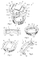
- FIG. 1 shows an exploded diagram through a floor passage 1 according to a first embodiment of the invention.
- the floor passage comprises an insert frame 2, which is provided with a floor flange 3 overlapping the edge 4 of a floor hole, see fig. 2 .
- the insert frame 2 is furthermore provided with a hole 5 through which electrical cables can be pulled up through the insert frame 2 and accordingly the floor.
- the insert frame is in addition provided with a lowered fold 6 for the mounting of a cover, which covers the entire hole 5.
- the cover consists of a first outer cover part 7 and a second outer cover part 8, which cover parts 7, 8 surround a cover object 9, which in figure 1 is formed as an inner cover part 10.
- the outer cover parts 7, 8 together with the cover object 9 form the cover, which after joining of the parts can be mounted in the fold 6 by means of a screw 11 through each cover part.
- guides 7.1 are inserted in guiding grooves 8.1, which are placed in the surfaces facing each other of the two cover parts 7, 8.
- Each cover part is also provided with a subjacent sealing part 12.1, 12.2 each, which in mounting joins end-to-end with each other.
- the sealing parts may join against each other along the entire facing edge surface or be provided with a central slot 12.3, as the figure shows.
- the sealing parts 12.1, 12.2 are glued in the cover parts 7, 8 in a sealing fold 13 intended therefor.
- the cover object 9 is provided with an edge groove 14 going around in the edge in order to be possible to be pushed in over edge flanges 15 of the outer cover parts.
- edge groove and the sealing folds will form an additional seal in the form of a labyrinth seal between the cover object and the two cover parts when the parts are mounted.
- the cover object is quadratically formed, which represents that the cover object can assume four different positions between the cover parts as well as that each position is locked in the direction of rotation by the edges thereof.
- the inner cover part 10 is connected to an outer cover part 7 via a line 16 in order to clamp the inner cover part when another cover object is connected.
- This line 16 may also be carried out as an earth cable in case some one of the parts needs to be earthed.
- the embodiment in figure 1 shows a circular insert frame 2, a circular floor flange 3, a circular hole 5, a circular fold 6 and a circular cover as well as a quadratic cover object 9, the individual geometrical shapes of these parts may be different within the scope of the invention.
- the cover object may be circularly shaped with a possibility of being steplessly turned between the cover parts as well as provided with some form of locking mechanism for a selected position.
- the insert frame may also be rectangularly or quadratically formed.
- Figure 2 shows the floor passage 1 mounted in a floor hole 21 in a section from the side where the floor flange 3 abuts against the floor surface 22.
- the insert frame 2 is provided with an attachment device in the form of one or more clamping jaws 23, which are horizontally movable, and are, in the case of a circular hole, radially movable.
- the clamping jaws will move horizontally outward when mounting screws placed in the circular fold are screwed downward in the insert frame 2.
- the clamping jaws 23 are arranged to move in the vertical direction when said mounting screws are screwed downward so that the insert frame 2 is pulled against the floor surface 22 for an optimum seal.
- the figure also shows a floor seal 24 placed between the floor flange 3 and the floor surface 22.
- Figure 3 shows the insert frame 2, which in the fold 6 thereof is provided with on one hand screw taps 31 for the fastening of the outer cover parts 7, 8 by means of the screws 11 thereof.
- the fold 6 is furthermore provided with fastening screws 32, which pull the clamping jaws 23 upward, the same simultaneously sliding outward, which will be shown under figure 5 .
- Figure 4 shows the floor passage 1 with the cover parts 7, 8 and the inner cover part 10 mounted in the insert frame 2 by means of cover screws 41.
- the figure also shows that the cover parts 7, 8 join to each other along a diagonal D to the circular insert frame 2, which represents that the two outer cover parts have the same geometrical shape.
- the inner cover part 10 is mounted, the floor passage is inactivated and connects to the floor surface in a plane and tight way.
- the seal is provided by the labyrinth seal between the inner cover part and the outer cover parts as well as by the subjacent sealing parts, which connect against each other.
- the seal may be increased by the floor seal shown in figure 2 between floor flange and floor surface.
- Figure 5 shows a section through the floor passage 1 with the inner cover part 10 mounted between the two outer cover parts 7, 8 of the insert frame 2. Also the subjacent sealing parts 12.1, 12.2 are seen in the figure.
- the clamping jaws 23 are mounted on the insert frame 2 so that these slide outward when the fastening screws are tightened. This is provided by the fact that the clamping jaws 23 are mounted on oblique sliding surfaces 51, 52, which entails that a displacement of the clamping jaws 23 against the floor flange 3 simultaneously provides a radial displacement outward of the clamping jaws 23.
- Figure 6 shows how the floor passage 1 is activated in order to house an outlet post 60, which in the foot 61 thereof is provided with a socket, which in shape and function is equal to the socket of the inner cover part 10 in order to replace the inner cover part as an alternative cover object 9 in of the cover.
- the outlet post may be shaped in a number of different ways with varying types of voltage outlets 62 and breakers. Also computer networks may be placed in these outlet posts.
- Figure 7 shows the floor passage 1 when an outlet post 60 is mounted.
- the outlet post can be orientated in four different locked directions.
- the foot 61 of the outlet post joins in this connection sealingly against the two outer cover parts 7, 8.
- the inner cover part hangs in the line thereof under the grommet, not shown in the figure.
- Figure 8 shows an alternative mounting of a cover object in the floor passage 1 in the form of a cable tie 81, which correspondingly is provided with a socket that in shape and function is equal to the socket of the inner cover part 10 in order to replace the inner cover part as an alternative cover object of the cover.
- a cable collection duct 73 is connected to the circular grommet 72 of the cable tie through which miscellaneous cabling is brought up through the floor and out to the different users in order to directly be connected to fixed connectors of the cabling.
- the cable tie 81 takes place correspondingly as mounting and dismounting of the outlet post shown in figure 6 .
- the cable tie is formed in two cone parts 83 in order to enable insertion of the cabling with the fixedly mounted connectors thereof.
- the cable tie is in addition provided with a strain relief 82 in the form of a hook, which is inserted through one of a plurality of slots 84 of the cable collection duct 73.
- the two cone parts 83 of the cable tie 81 being laid around the cable collection duct 73 and the strain relief 82 of one the parts is inserted into a suitable slot 84.
- the two cone parts 83 are in addition provided with guiding elements 85 so that the parts should fit in right opposite each other.
- Figure 9 shows the final mounting of the two-part cable tie 81 as cover object in the floor passage 1.
- the figure does however not show any cabling through the cable collection duct 73, but in this embodiment, a cabling is normally always pulled up through the floor passage and the cable collection duct connected thereto.
Landscapes
- Engineering & Computer Science (AREA)
- Architecture (AREA)
- Civil Engineering (AREA)
- Structural Engineering (AREA)
- Installation Of Indoor Wiring (AREA)
- Connection Or Junction Boxes (AREA)
- Body Structure For Vehicles (AREA)
- Connector Housings Or Holding Contact Members (AREA)
Abstract
Description
- The present invention relates to the area of floor passages or grommets for electrical cables.
- In office environments and lecture halls, there is a need of providing electrical wiring under raised floors, which are elevated in order to provide a space for the wiring, Grommets are used for being able to bring up cabling through such a floor at fixed locations in the floor. The background of the present invention is that grommets have been specialized to the respective fields of application thereof and have in that connection had entirely different aesthetics, have had different quality as well as varying function from different manufacturers. Thus, the background of the present invention is an aim to provide an improved floor passage, which can be used for varying fields of application.
- Floor passages from elevated raised floors under which miscellaneous wiring is made are present since earlier.
-
US 6 632 999 shows a floor passage for use in buildings and office environments where air-conditioning is carried out in a subjacent floor space where also wirings are arranged. The floor passage is formed as a frame connected to the floor, in which frame a number of bristle seals are arranged in order to in a simple way be able to pull up cables through the grommet and simultaneously limit outflowing conditioned air. - Furthermore, cable grommets are found intended for table surfaces, shelves and panels in office environments.
- For instance, in
US 7 141 744 , a panel grommet is seen for cables, which is formed as a lowered container in two halves which has been fitted into a circular hole of the panel. The cables may be pulled in through the container through holes between the parts thereof and up through the container. When the cables are not connected, these may be stored in the container, which also may be covered by a cover. - From
US 4 688 491 , a table grommet is seen in the form of a frame lowered in the table top, in which frame a cover having a sliding hatch is arranged for being able to enable that electrical cables are pulled through the table top. - All of these known devices enable that electrical cables are pulled through a panel of some type, but have the disadvantage that the grommets cannot be utilized for more applications than exactly for bringing electrical cables through a plane panel or the like.
- The present invention aims at providing an improved floor passage for electrical cables, which grommet is formed in a way that enables that it easily can be adapted to a plurality of applications.
- By the present invention, such as this appears in the independent claim, the above-mentioned object is fulfilled. Suitable embodiments of the invention are defined in the dependent claims.
- The invention relates to a floor passage comprising an insert frame provided with a centrally placed hole. Said insert frame may be circularly or rectangularly shaped and joins against the upperside of a floor surface by a collar, which may be provided with a seal in order to prevent that moisture penetrates down under the floor. The insert frame is provided with an attachment device for fastening in a floor hole, the upperside of the insert frame being provided with a fold for the mounting of a cover formed to cover said hole. The cover comprises two cover parts, a first outer cover part and a second outer cover part, which both cover parts are formed to enclose a cover object. The cover object is arranged to co-operate with said cover parts to a vertical fixation as well as closure of a central hole in the cover, all cover parts as well as the cover object being formed to be assembled upon or before mounting in the insert frame, The cover parts are fastened in the fold of the insert frame by means of screws, which have a design enabling that they always remain in the cover parts.
- A suitable embodiment is to form the hole of the insert frame circular. In connection with this embodiment, it is suitable that the cover having the two outer cover parts are formed to be connected to each other along a diameter in the circular hole.
- An additional suitable embodiment is that the cover as such is circularly shaped.
- The cover object of the cover is preferably formed with a rotation preventing member in the form of an edge.
- In order to vertically fix the cover object of the cover, the cover object, e.g., an inner cover part, is provided with an edge groove, which is arranged to be pushed in over the corresponding edge flanges of the outer cover parts. Alternatively, the cover object may be provided with an edge flange, which is arranged to be pushed in to a corresponding edge groove of the outer cover parts.
- In order to avoid leakage through the floor passage, it is advantageous as is seen in an embodiment to provide the outer cover parts with a sealing part each, which sealing parts are arranged to join and in addition be pressed against each other when the outer cover parts are mounted in the insert frame in order to seal the joints of the cover so that water and dust are prevented from penetrating down through the grommet. These sealing parts may in this connection each one be mounted in a sealing fold on the underside of the respective cover part.
- A suitable embodiment of the floor passage is that the insert frame is provided with an attachment mechanism in the form of at least one radially movable clamping jaw, preferably four clamping jaws, whichclamping jaw is arranged to be displaced outward toward the edge of the floor hole upon manoeuvre in order to fasten the grommet in the floor hole. In case the hole of the insert frame is circular, the clamping jaw will be pressed radially outward.
- In an additional embodiment, the attachment mechanism is axially movable and arranged to be displaced axially in relation to the insert frame so that the fold of the insert frame is pulled against the floor upon mounting.
- The cover object placed between the two outer cover parts of the floor passage is formed either as an inner cover part, as an outlet post or as a cable tie. When the cover object is formed as an inner cover part, the same is mounted on the same level as the outer cover parts and also on the same level as the floor flange in order to minimize the risk of stumbling. Furthermore, the inner cover part is connected with one of the outer cover parts via a line so that the inner cover part not should be lost when another type of cover object is used.
- When the cover object is formed as a cable tie, the same consists of two equal parts which makes it possible to use already contacted cables. Furthermore, the cable tie is formed with an attachment of a protective tube, which gives extra protection for the cables that are pulled through the cable tie. In addition, the cable tie may be provided with a strain relief.
- Also other designs of the cover object are feasible within the scope of the invention,
- The invention will now be described in more detail by means of embodiment examples, reference being made to the accompanying drawings, where
- figure 1
- shows an exploded diagram of an embodiment according to the present invention,
- figure 2
- shows a side view of an embodiment according to the present inven- tion mounted in a floor,
- figure 3
- shows a perspective view of an embodiment without cover as well as corresponding to the embodiment according to
fig. 2 , - figure 4
- shows a perspective view of the embodiment according to
fig. 3 with cover mounted, - figure 5
- shows a perspective view in section of the invention according to
fig. 4 with the cover mounted, - figure 6
- shows an exploded diagram of an embodiment having an outlet post according to the invention,
- figure 7
- shows a perspective view of an embodiment having an outlet post mounted,
- figure 8
- shows an exploded diagram of an embodiment having a cable tie according to the invention,
- figure 9
- shows an embodiment according to the invention having a cable tie mounted.
-
Figure 1 shows an exploded diagram through a floor passage 1 according to a first embodiment of the invention. The floor passage comprises aninsert frame 2, which is provided with a floor flange 3 overlapping theedge 4 of a floor hole, seefig. 2 . Theinsert frame 2 is furthermore provided with ahole 5 through which electrical cables can be pulled up through theinsert frame 2 and accordingly the floor. The insert frame is in addition provided with a lowered fold 6 for the mounting of a cover, which covers theentire hole 5. The cover consists of a firstouter cover part 7 and a second outer cover part 8, which coverparts 7, 8 surround a cover object 9, which infigure 1 is formed as aninner cover part 10. Theouter cover parts 7, 8 together with the cover object 9 form the cover, which after joining of the parts can be mounted in the fold 6 by means of ascrew 11 through each cover part. Upon joining of thecover parts 7, 8, guides 7.1 are inserted in guiding grooves 8.1, which are placed in the surfaces facing each other of the twocover parts 7, 8. Each cover part is also provided with a subjacent sealing part 12.1, 12.2 each, which in mounting joins end-to-end with each other. The sealing parts may join against each other along the entire facing edge surface or be provided with a central slot 12.3, as the figure shows. The sealing parts 12.1, 12.2 are glued in thecover parts 7, 8 in a sealing fold 13 intended therefor. The cover object 9 is provided with anedge groove 14 going around in the edge in order to be possible to be pushed in overedge flanges 15 of the outer cover parts. Thus, the edge groove and the sealing folds will form an additional seal in the form of a labyrinth seal between the cover object and the two cover parts when the parts are mounted. As is seen in the figure, the cover object is quadratically formed, which represents that the cover object can assume four different positions between the cover parts as well as that each position is locked in the direction of rotation by the edges thereof. - As is also seen in
figure 1 , theinner cover part 10 is connected to anouter cover part 7 via aline 16 in order to clamp the inner cover part when another cover object is connected. Thisline 16 may also be carried out as an earth cable in case some one of the parts needs to be earthed. - Even if the embodiment in
figure 1 shows acircular insert frame 2, a circular floor flange 3, acircular hole 5, a circular fold 6 and a circular cover as well as a quadratic cover object 9, the individual geometrical shapes of these parts may be different within the scope of the invention. For instance, the cover object may be circularly shaped with a possibility of being steplessly turned between the cover parts as well as provided with some form of locking mechanism for a selected position. The insert frame may also be rectangularly or quadratically formed. -
Figure 2 shows the floor passage 1 mounted in afloor hole 21 in a section from the side where the floor flange 3 abuts against thefloor surface 22. Theinsert frame 2 is provided with an attachment device in the form of one ormore clamping jaws 23, which are horizontally movable, and are, in the case of a circular hole, radially movable. The clamping jaws will move horizontally outward when mounting screws placed in the circular fold are screwed downward in theinsert frame 2. In addition, the clampingjaws 23 are arranged to move in the vertical direction when said mounting screws are screwed downward so that theinsert frame 2 is pulled against thefloor surface 22 for an optimum seal. The figure also shows afloor seal 24 placed between the floor flange 3 and thefloor surface 22. -
Figure 3 shows theinsert frame 2, which in the fold 6 thereof is provided with on one hand screw taps 31 for the fastening of theouter cover parts 7, 8 by means of thescrews 11 thereof. The fold 6 is furthermore provided withfastening screws 32, which pull the clampingjaws 23 upward, the same simultaneously sliding outward, which will be shown underfigure 5 . -
Figure 4 shows the floor passage 1 with thecover parts 7, 8 and theinner cover part 10 mounted in theinsert frame 2 by means of cover screws 41. The figure also shows that thecover parts 7, 8 join to each other along a diagonal D to thecircular insert frame 2, which represents that the two outer cover parts have the same geometrical shape. When theinner cover part 10 is mounted, the floor passage is inactivated and connects to the floor surface in a plane and tight way. The seal is provided by the labyrinth seal between the inner cover part and the outer cover parts as well as by the subjacent sealing parts, which connect against each other. In addition, the seal may be increased by the floor seal shown infigure 2 between floor flange and floor surface. -
Figure 5 shows a section through the floor passage 1 with theinner cover part 10 mounted between the twoouter cover parts 7, 8 of theinsert frame 2. Also the subjacent sealing parts 12.1, 12.2 are seen in the figure. As was mentioned in connection withfigure 3 , the clampingjaws 23 are mounted on theinsert frame 2 so that these slide outward when the fastening screws are tightened. This is provided by the fact that the clampingjaws 23 are mounted onoblique sliding surfaces jaws 23 against the floor flange 3 simultaneously provides a radial displacement outward of the clampingjaws 23. -
Figure 6 shows how the floor passage 1 is activated in order to house anoutlet post 60, which in thefoot 61 thereof is provided with a socket, which in shape and function is equal to the socket of theinner cover part 10 in order to replace the inner cover part as an alternative cover object 9 in of the cover. The outlet post may be shaped in a number of different ways with varying types ofvoltage outlets 62 and breakers. Also computer networks may be placed in these outlet posts. - In installation of an
outlet post 60 as cover object 9 instead of theinner cover part 10, first the fourcover screws 41 of the cover are backed out, the cover being lifted out of theinsert frame 2. The twoouter cover parts 7, 8 are pulled apart and theinner cover part 10 is taken out and is put down through the hole of theinsert frame 2 and becomes hanging in theline 16 thereof. After that, the two outer cover parts 8, 9 are mounted on thefoot 61 of the outlet post and are pushed in until they abut against each other whereupon the outlet post and the cover parts are put into the fold 6 of the insert frame, and the four cover screws again being tightened. These four screws are each one provided with end stops in order to avoid that they fall out of the screw holes thereof. -
Figure 7 shows the floor passage 1 when anoutlet post 60 is mounted. By the fact that the cover object is quadratically formed, the outlet post can be orientated in four different locked directions. Thefoot 61 of the outlet post joins in this connection sealingly against the twoouter cover parts 7, 8. Simultaneously, the inner cover part hangs in the line thereof under the grommet, not shown in the figure. -
Figure 8 shows an alternative mounting of a cover object in the floor passage 1 in the form of acable tie 81, which correspondingly is provided with a socket that in shape and function is equal to the socket of theinner cover part 10 in order to replace the inner cover part as an alternative cover object of the cover. To thecircular grommet 72 of the cable tie, acable collection duct 73 is connected through which miscellaneous cabling is brought up through the floor and out to the different users in order to directly be connected to fixed connectors of the cabling. - Mounting and dismounting of the
cable tie 81 takes place correspondingly as mounting and dismounting of the outlet post shown infigure 6 . However, the cable tie is formed in twocone parts 83 in order to enable insertion of the cabling with the fixedly mounted connectors thereof. The cable tie is in addition provided with astrain relief 82 in the form of a hook, which is inserted through one of a plurality ofslots 84 of thecable collection duct 73. For the mounting of the cabling, the same, which already runs through thecable collection duct 73, is brought up through the hole of theinsert frame 2, the twocone parts 83 of thecable tie 81 being laid around thecable collection duct 73 and thestrain relief 82 of one the parts is inserted into asuitable slot 84. After that, the mounting continues according to what has previously been described. The twocone parts 83 are in addition provided with guidingelements 85 so that the parts should fit in right opposite each other. -
Figure 9 shows the final mounting of the two-part cable tie 81 as cover object in the floor passage 1. The figure does however not show any cabling through thecable collection duct 73, but in this embodiment, a cabling is normally always pulled up through the floor passage and the cable collection duct connected thereto.
Claims (13)
- Floor passage (1) comprising an insert frame (2) provided with a centrally placed hole (5), which insert frame (2) is provided with an attachment device for fastening in a floor hole (21), the upperside of the insert frame (2) being provided with a fold (6) for the mounting of a cover (7, 8, 9) formed to cover said hole (5), the cover (7, 8, 9) comprising a first outer cover part (7) and a second outer cover part (8), which two cover parts (7, 8) are formed in order to surround a cover object (9), which is arranged to co-operate with said cover parts (7, 8) to a fixation in the cover (7, 8, 9), all cover parts (7, 8) as well as the cover object (9) being formed to be assembled in mounting in the fold (6) of the insert frame (2), characterized in that the cover object (9) is provided with an edge groove (14), which is arranged to be pushed in over corresponding edge flanges (15) of the outer cover parts (7, 8) or that the cover object (9) is provided with an edge flange, which is arranged to be pushed into a corresponding edge groove of the outer cover parts (7, 8), in order to form a seal in the form of a labyrinth seal between the cover object and the two cover parts when the parts are mounted.
- Floor passage according to claim 1, characterized in that the hole (5) of the insert frame (2) is circularly shaped.
- Floor passage according to claim 2, characterized in that the two outer cover parts (7, 8) are formed to be joined to each other along a diameter in the circular hole (5).
- Floor passage according to any one of claims 1-3, characterized in that the cover (7, 8, 9) is circular.
- Floor passage according to any one of claims 1-4, characterized in that the cover object (9) is formed with a rotation preventing member, for instance in the form of an edge.
- Floor passage according to any one of claims 1-5, characterized in that the outer cover parts (7, 8) are provided with a sealing part (12.1, 12.2) each, which sealing parts are arranged to join against each other when the outer cover parts (7, 8) are mounted in the insert frame (2).
- Floor passage according to claim 6, characterized in that the sealing parts (12.1, 12.2) each one are mounted in a sealing fold (13) on the underside of the respective cover part (7, 8).
- Floor passage according to any one of claims 1-7, characterized in that the attachment device consists of at least one horizontally movable clamping jaw (23), which is arranged to be displaced outward against the edge (4) of the floor hole (21) upon the manoeuvre thereof in order to fasten the grommet (1) in the floor hole (21).
- Floor passage according to claim 8, characterized in that the clamping jaw (23) is axially movable and arranged to be displaced axially in relation to the insert frame (2) so that the fold (3) thereof is pulled against the floor (22) in mounting.
- Floor passage according to any one of claims 1-9, characterized in that the cover object (9) is formed as an outlet post (60) intended to be mounted between the two cover parts (7, 8) of the floor passage (1).
- Floor passage according to any one of claims 1-9, characterized in that the cover object (9) is formed as a partable cable tie (81) intended to be mounted between the two cover parts (7, 8) of the floor passage (1).
- Floor passage according to claim 11, characterized in that at least one part of the cable tie (81) is provided with a strain relief (82).
- Floor passage according to any one of claims 1-9, characterized in that the cover object (9) is formed as an inner cover part (10) intended to be mounted on the same level as and between the two cover parts (7, 8) of the floor passage (1).
Applications Claiming Priority (1)
| Application Number | Priority Date | Filing Date | Title |
|---|---|---|---|
| SE0702041A SE532766C2 (en) | 2007-09-13 | 2007-09-13 | Floor Grommet |
Publications (3)
| Publication Number | Publication Date |
|---|---|
| EP2037551A2 true EP2037551A2 (en) | 2009-03-18 |
| EP2037551A3 EP2037551A3 (en) | 2010-12-22 |
| EP2037551B1 EP2037551B1 (en) | 2018-04-04 |
Family
ID=40114028
Family Applications (1)
| Application Number | Title | Priority Date | Filing Date |
|---|---|---|---|
| EP08164131.8A Not-in-force EP2037551B1 (en) | 2007-09-13 | 2008-09-11 | Floor passage |
Country Status (2)
| Country | Link |
|---|---|
| EP (1) | EP2037551B1 (en) |
| SE (1) | SE532766C2 (en) |
Citations (3)
| Publication number | Priority date | Publication date | Assignee | Title |
|---|---|---|---|---|
| US4688491A (en) | 1986-09-08 | 1987-08-25 | Allsteel Inc. | Grommet arrangement for office furniture desk tops |
| US6632999B2 (en) | 2001-09-13 | 2003-10-14 | Triton Technology Systems, Inc. | Toolless, self closing floor grommet closure for cable openings and the like in raised floors of data centers office buildings and other air conditioned structures |
| US7141744B2 (en) | 2004-11-22 | 2006-11-28 | Nicolet Plastique Ltee | Wire grommet |
Family Cites Families (3)
| Publication number | Priority date | Publication date | Assignee | Title |
|---|---|---|---|---|
| DE1874061U (en) * | 1963-01-31 | 1963-06-20 | Siemens Ag | CONNECTOR. |
| GB9204531D0 (en) * | 1992-03-03 | 1992-04-15 | Powerplan Systems Ltd | Service access devices |
| US20070277457A1 (en) * | 2006-06-02 | 2007-12-06 | Steelcase Development Corporation | Floor assembly utility panel |
-
2007
- 2007-09-13 SE SE0702041A patent/SE532766C2/en not_active IP Right Cessation
-
2008
- 2008-09-11 EP EP08164131.8A patent/EP2037551B1/en not_active Not-in-force
Patent Citations (3)
| Publication number | Priority date | Publication date | Assignee | Title |
|---|---|---|---|---|
| US4688491A (en) | 1986-09-08 | 1987-08-25 | Allsteel Inc. | Grommet arrangement for office furniture desk tops |
| US6632999B2 (en) | 2001-09-13 | 2003-10-14 | Triton Technology Systems, Inc. | Toolless, self closing floor grommet closure for cable openings and the like in raised floors of data centers office buildings and other air conditioned structures |
| US7141744B2 (en) | 2004-11-22 | 2006-11-28 | Nicolet Plastique Ltee | Wire grommet |
Also Published As
| Publication number | Publication date |
|---|---|
| EP2037551A3 (en) | 2010-12-22 |
| SE0702041L (en) | 2009-03-14 |
| EP2037551B1 (en) | 2018-04-04 |
| SE532766C2 (en) | 2010-04-06 |
Similar Documents
| Publication | Publication Date | Title |
|---|---|---|
| US9966745B2 (en) | Roof top junction box | |
| US10034539B2 (en) | Connector hub and modular work system | |
| US5685113A (en) | Lay-in wireways for a space divider system | |
| US5541363A (en) | Wet-environment electrical juncton box and method of making | |
| JP3307631B2 (en) | Electrified wall panel system | |
| US9966752B2 (en) | Deployable ceiling box assembly | |
| CN101399434B (en) | Sealing assembly | |
| US4375010A (en) | Panel construction including electrical connectors | |
| US8178795B2 (en) | Method for retrofitting air plenum grommets | |
| US6061984A (en) | Under floor reconfigurable utilities support structure | |
| US9825442B2 (en) | Conduit system and method | |
| US11025041B2 (en) | Weatherproof electrical enclosure with reinforcement | |
| CN1112740A (en) | Expandable surface raceway for wiring | |
| US5195286A (en) | Ceiling infeed module | |
| US5736673A (en) | Cable and mounting bracket assembly and method | |
| CA2575688A1 (en) | Power and communications distribution using a structural channel system | |
| CN1148423A (en) | Junction boxes for low-profile floors | |
| US10781967B1 (en) | Wall anchoring system with cable pass through | |
| US11916364B2 (en) | Mountable electrical enclosure with conduit passthrough | |
| US7427050B2 (en) | Apparatus for adjustably retaining and sealing pathway conduits mounted extending through a wall panel | |
| EP2037551B1 (en) | Floor passage | |
| KR101985811B1 (en) | Cable supporter of apartment building | |
| US7926231B2 (en) | Apparatus and method of routing cabling around leveler legs in a thin modular office panel | |
| US9337636B2 (en) | Modular fastening system | |
| US5339585A (en) | Raceway swivel spacer leg assembly |
Legal Events
| Date | Code | Title | Description |
|---|---|---|---|
| PUAI | Public reference made under article 153(3) epc to a published international application that has entered the european phase |
Free format text: ORIGINAL CODE: 0009012 |
|
| AK | Designated contracting states |
Kind code of ref document: A2 Designated state(s): AT BE BG CH CY CZ DE DK EE ES FI FR GB GR HR HU IE IS IT LI LT LU LV MC MT NL NO PL PT RO SE SI SK TR |
|
| AX | Request for extension of the european patent |
Extension state: AL BA MK RS |
|
| PUAL | Search report despatched |
Free format text: ORIGINAL CODE: 0009013 |
|
| AK | Designated contracting states |
Kind code of ref document: A3 Designated state(s): AT BE BG CH CY CZ DE DK EE ES FI FR GB GR HR HU IE IS IT LI LT LU LV MC MT NL NO PL PT RO SE SI SK TR |
|
| AX | Request for extension of the european patent |
Extension state: AL BA MK RS |
|
| 17P | Request for examination filed |
Effective date: 20110622 |
|
| AKX | Designation fees paid |
Designated state(s): AT BE BG CH CY CZ DE DK EE ES FI FR GB GR HR HU IE IS IT LI LT LU LV MC MT NL NO PL PT RO SE SI SK TR |
|
| 17Q | First examination report despatched |
Effective date: 20150902 |
|
| GRAP | Despatch of communication of intention to grant a patent |
Free format text: ORIGINAL CODE: EPIDOSNIGR1 |
|
| INTG | Intention to grant announced |
Effective date: 20171109 |
|
| GRAS | Grant fee paid |
Free format text: ORIGINAL CODE: EPIDOSNIGR3 |
|
| GRAA | (expected) grant |
Free format text: ORIGINAL CODE: 0009210 |
|
| AK | Designated contracting states |
Kind code of ref document: B1 Designated state(s): AT BE BG CH CY CZ DE DK EE ES FI FR GB GR HR HU IE IS IT LI LT LU LV MC MT NL NO PL PT RO SE SI SK TR |
|
| REG | Reference to a national code |
Ref country code: GB Ref legal event code: FG4D |
|
| REG | Reference to a national code |
Ref country code: CH Ref legal event code: EP |
|
| REG | Reference to a national code |
Ref country code: AT Ref legal event code: REF Ref document number: 986579 Country of ref document: AT Kind code of ref document: T Effective date: 20180415 |
|
| REG | Reference to a national code |
Ref country code: IE Ref legal event code: FG4D |
|
| REG | Reference to a national code |
Ref country code: DE Ref legal event code: R096 Ref document number: 602008054651 Country of ref document: DE |
|
| REG | Reference to a national code |
Ref country code: NL Ref legal event code: MP Effective date: 20180404 |
|
| REG | Reference to a national code |
Ref country code: LT Ref legal event code: MG4D |
|
| PG25 | Lapsed in a contracting state [announced via postgrant information from national office to epo] |
Ref country code: NL Free format text: LAPSE BECAUSE OF FAILURE TO SUBMIT A TRANSLATION OF THE DESCRIPTION OR TO PAY THE FEE WITHIN THE PRESCRIBED TIME-LIMIT Effective date: 20180404 |
|
| PG25 | Lapsed in a contracting state [announced via postgrant information from national office to epo] |
Ref country code: LT Free format text: LAPSE BECAUSE OF FAILURE TO SUBMIT A TRANSLATION OF THE DESCRIPTION OR TO PAY THE FEE WITHIN THE PRESCRIBED TIME-LIMIT Effective date: 20180404 Ref country code: NO Free format text: LAPSE BECAUSE OF FAILURE TO SUBMIT A TRANSLATION OF THE DESCRIPTION OR TO PAY THE FEE WITHIN THE PRESCRIBED TIME-LIMIT Effective date: 20180704 Ref country code: PL Free format text: LAPSE BECAUSE OF FAILURE TO SUBMIT A TRANSLATION OF THE DESCRIPTION OR TO PAY THE FEE WITHIN THE PRESCRIBED TIME-LIMIT Effective date: 20180404 Ref country code: ES Free format text: LAPSE BECAUSE OF FAILURE TO SUBMIT A TRANSLATION OF THE DESCRIPTION OR TO PAY THE FEE WITHIN THE PRESCRIBED TIME-LIMIT Effective date: 20180404 Ref country code: SE Free format text: LAPSE BECAUSE OF FAILURE TO SUBMIT A TRANSLATION OF THE DESCRIPTION OR TO PAY THE FEE WITHIN THE PRESCRIBED TIME-LIMIT Effective date: 20180404 Ref country code: BG Free format text: LAPSE BECAUSE OF FAILURE TO SUBMIT A TRANSLATION OF THE DESCRIPTION OR TO PAY THE FEE WITHIN THE PRESCRIBED TIME-LIMIT Effective date: 20180704 Ref country code: FI Free format text: LAPSE BECAUSE OF FAILURE TO SUBMIT A TRANSLATION OF THE DESCRIPTION OR TO PAY THE FEE WITHIN THE PRESCRIBED TIME-LIMIT Effective date: 20180404 |
|
| PG25 | Lapsed in a contracting state [announced via postgrant information from national office to epo] |
Ref country code: LV Free format text: LAPSE BECAUSE OF FAILURE TO SUBMIT A TRANSLATION OF THE DESCRIPTION OR TO PAY THE FEE WITHIN THE PRESCRIBED TIME-LIMIT Effective date: 20180404 Ref country code: HR Free format text: LAPSE BECAUSE OF FAILURE TO SUBMIT A TRANSLATION OF THE DESCRIPTION OR TO PAY THE FEE WITHIN THE PRESCRIBED TIME-LIMIT Effective date: 20180404 Ref country code: GR Free format text: LAPSE BECAUSE OF FAILURE TO SUBMIT A TRANSLATION OF THE DESCRIPTION OR TO PAY THE FEE WITHIN THE PRESCRIBED TIME-LIMIT Effective date: 20180705 |
|
| REG | Reference to a national code |
Ref country code: AT Ref legal event code: MK05 Ref document number: 986579 Country of ref document: AT Kind code of ref document: T Effective date: 20180404 |
|
| PG25 | Lapsed in a contracting state [announced via postgrant information from national office to epo] |
Ref country code: PT Free format text: LAPSE BECAUSE OF FAILURE TO SUBMIT A TRANSLATION OF THE DESCRIPTION OR TO PAY THE FEE WITHIN THE PRESCRIBED TIME-LIMIT Effective date: 20180806 |
|
| REG | Reference to a national code |
Ref country code: DE Ref legal event code: R097 Ref document number: 602008054651 Country of ref document: DE |
|
| PG25 | Lapsed in a contracting state [announced via postgrant information from national office to epo] |
Ref country code: AT Free format text: LAPSE BECAUSE OF FAILURE TO SUBMIT A TRANSLATION OF THE DESCRIPTION OR TO PAY THE FEE WITHIN THE PRESCRIBED TIME-LIMIT Effective date: 20180404 Ref country code: DK Free format text: LAPSE BECAUSE OF FAILURE TO SUBMIT A TRANSLATION OF THE DESCRIPTION OR TO PAY THE FEE WITHIN THE PRESCRIBED TIME-LIMIT Effective date: 20180404 Ref country code: RO Free format text: LAPSE BECAUSE OF FAILURE TO SUBMIT A TRANSLATION OF THE DESCRIPTION OR TO PAY THE FEE WITHIN THE PRESCRIBED TIME-LIMIT Effective date: 20180404 Ref country code: SK Free format text: LAPSE BECAUSE OF FAILURE TO SUBMIT A TRANSLATION OF THE DESCRIPTION OR TO PAY THE FEE WITHIN THE PRESCRIBED TIME-LIMIT Effective date: 20180404 Ref country code: CZ Free format text: LAPSE BECAUSE OF FAILURE TO SUBMIT A TRANSLATION OF THE DESCRIPTION OR TO PAY THE FEE WITHIN THE PRESCRIBED TIME-LIMIT Effective date: 20180404 Ref country code: EE Free format text: LAPSE BECAUSE OF FAILURE TO SUBMIT A TRANSLATION OF THE DESCRIPTION OR TO PAY THE FEE WITHIN THE PRESCRIBED TIME-LIMIT Effective date: 20180404 |
|
| PLBE | No opposition filed within time limit |
Free format text: ORIGINAL CODE: 0009261 |
|
| STAA | Information on the status of an ep patent application or granted ep patent |
Free format text: STATUS: NO OPPOSITION FILED WITHIN TIME LIMIT |
|
| PG25 | Lapsed in a contracting state [announced via postgrant information from national office to epo] |
Ref country code: IT Free format text: LAPSE BECAUSE OF FAILURE TO SUBMIT A TRANSLATION OF THE DESCRIPTION OR TO PAY THE FEE WITHIN THE PRESCRIBED TIME-LIMIT Effective date: 20180404 |
|
| 26N | No opposition filed |
Effective date: 20190107 |
|
| REG | Reference to a national code |
Ref country code: DE Ref legal event code: R119 Ref document number: 602008054651 Country of ref document: DE |
|
| PG25 | Lapsed in a contracting state [announced via postgrant information from national office to epo] |
Ref country code: MC Free format text: LAPSE BECAUSE OF FAILURE TO SUBMIT A TRANSLATION OF THE DESCRIPTION OR TO PAY THE FEE WITHIN THE PRESCRIBED TIME-LIMIT Effective date: 20180404 |
|
| REG | Reference to a national code |
Ref country code: CH Ref legal event code: PL |
|
| GBPC | Gb: european patent ceased through non-payment of renewal fee |
Effective date: 20180911 |
|
| PG25 | Lapsed in a contracting state [announced via postgrant information from national office to epo] |
Ref country code: SI Free format text: LAPSE BECAUSE OF FAILURE TO SUBMIT A TRANSLATION OF THE DESCRIPTION OR TO PAY THE FEE WITHIN THE PRESCRIBED TIME-LIMIT Effective date: 20180404 |
|
| REG | Reference to a national code |
Ref country code: BE Ref legal event code: MM Effective date: 20180930 |
|
| REG | Reference to a national code |
Ref country code: IE Ref legal event code: MM4A |
|
| PG25 | Lapsed in a contracting state [announced via postgrant information from national office to epo] |
Ref country code: LU Free format text: LAPSE BECAUSE OF NON-PAYMENT OF DUE FEES Effective date: 20180911 |
|
| PG25 | Lapsed in a contracting state [announced via postgrant information from national office to epo] |
Ref country code: DE Free format text: LAPSE BECAUSE OF NON-PAYMENT OF DUE FEES Effective date: 20190402 Ref country code: IE Free format text: LAPSE BECAUSE OF NON-PAYMENT OF DUE FEES Effective date: 20180911 |
|
| PG25 | Lapsed in a contracting state [announced via postgrant information from national office to epo] |
Ref country code: BE Free format text: LAPSE BECAUSE OF NON-PAYMENT OF DUE FEES Effective date: 20180930 Ref country code: CH Free format text: LAPSE BECAUSE OF NON-PAYMENT OF DUE FEES Effective date: 20180930 Ref country code: LI Free format text: LAPSE BECAUSE OF NON-PAYMENT OF DUE FEES Effective date: 20180930 Ref country code: FR Free format text: LAPSE BECAUSE OF NON-PAYMENT OF DUE FEES Effective date: 20180930 |
|
| PG25 | Lapsed in a contracting state [announced via postgrant information from national office to epo] |
Ref country code: GB Free format text: LAPSE BECAUSE OF NON-PAYMENT OF DUE FEES Effective date: 20180911 |
|
| PG25 | Lapsed in a contracting state [announced via postgrant information from national office to epo] |
Ref country code: MT Free format text: LAPSE BECAUSE OF NON-PAYMENT OF DUE FEES Effective date: 20180911 |
|
| PG25 | Lapsed in a contracting state [announced via postgrant information from national office to epo] |
Ref country code: TR Free format text: LAPSE BECAUSE OF FAILURE TO SUBMIT A TRANSLATION OF THE DESCRIPTION OR TO PAY THE FEE WITHIN THE PRESCRIBED TIME-LIMIT Effective date: 20180404 |
|
| PG25 | Lapsed in a contracting state [announced via postgrant information from national office to epo] |
Ref country code: HU Free format text: LAPSE BECAUSE OF FAILURE TO SUBMIT A TRANSLATION OF THE DESCRIPTION OR TO PAY THE FEE WITHIN THE PRESCRIBED TIME-LIMIT; INVALID AB INITIO Effective date: 20080911 |
|
| PG25 | Lapsed in a contracting state [announced via postgrant information from national office to epo] |
Ref country code: CY Free format text: LAPSE BECAUSE OF FAILURE TO SUBMIT A TRANSLATION OF THE DESCRIPTION OR TO PAY THE FEE WITHIN THE PRESCRIBED TIME-LIMIT Effective date: 20180404 |
|
| PG25 | Lapsed in a contracting state [announced via postgrant information from national office to epo] |
Ref country code: IS Free format text: LAPSE BECAUSE OF FAILURE TO SUBMIT A TRANSLATION OF THE DESCRIPTION OR TO PAY THE FEE WITHIN THE PRESCRIBED TIME-LIMIT Effective date: 20180804 |