US7141744B2 - Wire grommet - Google Patents
Wire grommet Download PDFInfo
- Publication number
- US7141744B2 US7141744B2 US11/250,858 US25085805A US7141744B2 US 7141744 B2 US7141744 B2 US 7141744B2 US 25085805 A US25085805 A US 25085805A US 7141744 B2 US7141744 B2 US 7141744B2
- Authority
- US
- United States
- Prior art keywords
- elements
- container
- grommet
- assembled
- closing cap
- Prior art date
- Legal status (The legal status is an assumption and is not a legal conclusion. Google has not performed a legal analysis and makes no representation as to the accuracy of the status listed.)
- Expired - Fee Related
Links
- 210000002105 tongue Anatomy 0.000 claims abstract description 6
- 230000013011 mating Effects 0.000 claims 2
- 239000000463 material Substances 0.000 claims 1
- 239000002991 molded plastic Substances 0.000 claims 1
- 238000004519 manufacturing process Methods 0.000 description 3
- 230000037431 insertion Effects 0.000 description 1
- 238000003780 insertion Methods 0.000 description 1
- 238000000465 moulding Methods 0.000 description 1
Images


Classifications
-
- A—HUMAN NECESSITIES
- A47—FURNITURE; DOMESTIC ARTICLES OR APPLIANCES; COFFEE MILLS; SPICE MILLS; SUCTION CLEANERS IN GENERAL
- A47B—TABLES; DESKS; OFFICE FURNITURE; CABINETS; DRAWERS; GENERAL DETAILS OF FURNITURE
- A47B21/00—Tables or desks for office equipment, e.g. typewriters, keyboards
- A47B21/06—Tables or desks for office equipment, e.g. typewriters, keyboards characterised by means for holding, fastening or concealing cables
-
- A—HUMAN NECESSITIES
- A47—FURNITURE; DOMESTIC ARTICLES OR APPLIANCES; COFFEE MILLS; SPICE MILLS; SUCTION CLEANERS IN GENERAL
- A47B—TABLES; DESKS; OFFICE FURNITURE; CABINETS; DRAWERS; GENERAL DETAILS OF FURNITURE
- A47B2200/00—General construction of tables or desks
- A47B2200/008—Tables or desks having means for applying electronic or electric devices
- A47B2200/0082—Cable inlet in worktop or desk, e.g. grommet
Definitions
- the present invention relates to a wire grommet intended to be positioned in a hole made in a surface of a panel or plate, especially a table or a desk.
- This wire grommet is devised to let one or more wires pass through it while also acting as a pen holder or a storing space.
- the object of the present invention is to provide a piece intended to be inserted into a hole made into a plate or a panel in order to, on the one hand, always permit to this hole to act as a wire grommet and, on the other hand, act as a pen holder or form a storing space.
- the invention is directed to a wire grommet intended to be positioned into a hole made into the surface of a panel or plate.
- This grommet comprises two identical elements having adjacent edges provided with tongues and grooves allowing their assembly to form an open container with a size and shape adapted to allow it to be inserted into the hole and be maintained within the same.
- the elements also have recesses in their edges which altogether form at least one opening through which one or more wires may pass when the elements are assembled.
- the wire grommet also comprises a closing cap fittable into both elements when the elements are assembled, in order to close the container formed by the same.
- the motion of the cap during its insertion into the container, is limited by an edge acting as a stop.
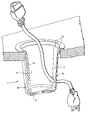
- FIG. 1 is a perspective view in partial cross-section of a wire grommet according to the invention installed in a hole made into a surface of a panel or plate;
- FIG. 2 is an exploded perspective view of the wire grommet shown in FIG. 1 , which illustrates the two basic elements forming the same, as well as its lid;
- FIGS. 3 to 6 are perspective view, a top plan view, a front elevational view and a side elevational view of the wire grommet shown in FIGS. 1 and 2 ;
- FIGS. 7 , 8 , 9 and 10 are respectively a perspective view, a top plan view, a front elevational and a side elevational view of one of the two elements forming the wire grommet illustrated in the previous Figures.
- the wire grommet 1 according to the preferred embodiment of the invention shown in the accompanying drawings, are made of two identical elements 3 and 5 which form an open container when they are assembled together.
- tongues 9 and grooves 11 are provided into the lateral edges of the elements 3 and 5 in order to assemble and disassemble the same at will.
- Tongues and grooves may also be provided on the bottom of each of the elements so as to complete their assembly.
- Each element 3 , 5 comprises an upper rim 13 which projects outwardly in order to fit onto the edges of the hole of the panel into which the wire grommet is intended to be positioned (see FIG. 1 ).
- the upper rim 13 may also mask the imperfections that may exist all around the hole, especially if this one is made into the panel by a user.
- Each of the elements 3 , 5 also comprises at least one recess 15 on one of its edges preferably close to its bottom in order to, once both elements are assembled around a wire, let this wire pass through the same as is clearly shown in FIG. 1 .
- the wire grommet 1 according to the invention may also comprise a closing cap 17 (see FIG. 2 ) sized to fit onto a recess provided for this purpose in the upper part of each of the elements 3 , 5 .
- the cap may be provided with an openable part 19 in order to let the electric wire pass through it, if need be.
- This closing cap is that it reduces the size of the opening and the risk of letting fall by inadvertence a pen, an eraser, or any other item that could be placed onto the panel or plate in which the wire grommet is installed.
- each element 3 , 5 can be molded in a very thin manner.
- the parts of the elements that act as supporting means or as connecting means must however be thicker in order to provide the necessary resistance and durability.
- the two elements that form the wire grommet according to the invention are identical.
- the mold used for manufacturing the wire grommet is made of two very simple parts, including a male part and a female part to form each grommet.
- the mold is however preferably devised in such a manner as to comprise two identical male parts and two identical female parts so as to form two identical elements at the same time.
- the advantage of this molding is that it permits to obtain the requested wire grommet without using expensive mechanical components. Such permits to improve the production costs.
- the wire grommet according to the invention as shown in an assembled manner, in FIGS. 1 and 3 to 6 , permits to avoid that objects placed on the panel or plate fall by inadvertence into the hole where the wire grommet has been installed. Thanks to its structure and shape, this wire grommet may also act as a pen holder. It can be understood however that it could also be used for other storage purposes.
Landscapes
- Installation Of Indoor Wiring (AREA)
- Insulating Bodies (AREA)
- Purses, Travelling Bags, Baskets, Or Suitcases (AREA)
- Packaging Of Annular Or Rod-Shaped Articles, Wearing Apparel, Cassettes, Or The Like (AREA)
- Pens And Brushes (AREA)
- Mechanical Pencils And Projecting And Retracting Systems Therefor, And Multi-System Writing Instruments (AREA)
Abstract
Disclosed is a wire grommet intended to be positioned in a hole made into a surface of a panel or plate. The grommet is made of two identical elements having adjacent edges provided with tongues and grooves allowing them to be assembled to form an open container with a size and shape adapted to allow it to be inserted into the hole and be maintained within the same. The elements also have recesses in their edges which altogether form at least one opening through which one or more wires may pass when the elements are assembled. Advantageously, the wire grommet also comprises a closing cap fittable into both elements when the elements are assembled, in order to close the container formed by the same.
Description
The present invention relates to a wire grommet intended to be positioned in a hole made in a surface of a panel or plate, especially a table or a desk. This wire grommet is devised to let one or more wires pass through it while also acting as a pen holder or a storing space.
In the field of furniture, especially desks, tables or shelves, it is of common practice to provide holes in the surface of plates or panels so as to pass wires necessary to connect the electrical or electronic equipment. However, in practice, these holes often remain unused.
The object of the present invention is to provide a piece intended to be inserted into a hole made into a plate or a panel in order to, on the one hand, always permit to this hole to act as a wire grommet and, on the other hand, act as a pen holder or form a storing space.
More specifically, the invention is directed to a wire grommet intended to be positioned into a hole made into the surface of a panel or plate. This grommet comprises two identical elements having adjacent edges provided with tongues and grooves allowing their assembly to form an open container with a size and shape adapted to allow it to be inserted into the hole and be maintained within the same. The elements also have recesses in their edges which altogether form at least one opening through which one or more wires may pass when the elements are assembled.
Preferably, the wire grommet also comprises a closing cap fittable into both elements when the elements are assembled, in order to close the container formed by the same. The motion of the cap during its insertion into the container, is limited by an edge acting as a stop.
The invention will be better understood upon reading the following non-restrictive description of a preferred embodiment thereof, made with reference to the accompanying drawings.
The wire grommet 1 according to the preferred embodiment of the invention shown in the accompanying drawings, are made of two identical elements 3 and 5 which form an open container when they are assembled together. In order to proceed to this assembly, tongues 9 and grooves 11 are provided into the lateral edges of the elements 3 and 5 in order to assemble and disassemble the same at will. Tongues and grooves may also be provided on the bottom of each of the elements so as to complete their assembly.
Each element 3, 5 comprises an upper rim 13 which projects outwardly in order to fit onto the edges of the hole of the panel into which the wire grommet is intended to be positioned (see FIG. 1 ). The upper rim 13 may also mask the imperfections that may exist all around the hole, especially if this one is made into the panel by a user.
Each of the elements 3, 5 also comprises at least one recess 15 on one of its edges preferably close to its bottom in order to, once both elements are assembled around a wire, let this wire pass through the same as is clearly shown in FIG. 1 .
Advantageously, the wire grommet 1 according to the invention may also comprise a closing cap 17 (see FIG. 2 ) sized to fit onto a recess provided for this purpose in the upper part of each of the elements 3,5. The cap may be provided with an openable part 19 in order to let the electric wire pass through it, if need be. The advantage of this closing cap is that it reduces the size of the opening and the risk of letting fall by inadvertence a pen, an eraser, or any other item that could be placed onto the panel or plate in which the wire grommet is installed.
In order to reduce as much as possible the fabrication costs, the walls of each element 3,5 can be molded in a very thin manner. The parts of the elements that act as supporting means or as connecting means must however be thicker in order to provide the necessary resistance and durability.
As is clearly shown in the drawings, the two elements that form the wire grommet according to the invention are identical. The mold used for manufacturing the wire grommet is made of two very simple parts, including a male part and a female part to form each grommet. The mold is however preferably devised in such a manner as to comprise two identical male parts and two identical female parts so as to form two identical elements at the same time. The advantage of this molding is that it permits to obtain the requested wire grommet without using expensive mechanical components. Such permits to improve the production costs.
It can be understood that once installed, the wire grommet according to the invention as shown in an assembled manner, in FIGS. 1 and 3 to 6, permits to avoid that objects placed on the panel or plate fall by inadvertence into the hole where the wire grommet has been installed. Thanks to its structure and shape, this wire grommet may also act as a pen holder. It can be understood however that it could also be used for other storage purposes.
Claims (5)
1. A wire grommet to be positioned into a hole in a surface of a panel or plate, said grommet comprising:
two identical elements having opposing elongated edges provided with mating tongues and grooves allowing assembly of said elements to form a container with an open top end, a closed bottom end opposite said open top end, and being of a size and shape adapted to allow it to be inserted into the hole and be maintained within the same;
each of said elements having at least one recess in at least one of the opposing edges positioned to form, when said elements are assembled, at least one opening above said closed bottom end through which one or more wires may pass, while allowing said container to act as a containment part in which objects can be inserted and held; and
further comprising a closing cap fittable into both elements when said elements are assembled to close the open end of the container formed by said two elements.
2. The wire grommet of claim 1 , wherein said elements are made of molded plastic material.
3. The wire grommet of claim 1 , wherein said at least one opening is located close to the closed bottom end of the container.
4. The wire grommet of claim 1 , wherein said closing cap is provided with an openable part for allowing one or more wires to pass through said closing cap.
5. A wire grommet to be positioned in a hole in a surface of a panel or plate, said grommet comprising:
two identical elements having opposed elongated edges provided with mating tongues and grooves allowing their assembly to form an open container with an open top end, a closed bottom end opposite to said open top end, and being of a size and shape adapted to allow the assembled elements to be inserted into and maintained within the hole,
said elements also have at least one recess in at least one of the opposed edges which form, when said elements are assembled, at least one opening through which one or more wires may pass, each said at least one opening being located above and close to the closed bottom end of the container, said closed bottom to allow said container to act as a containment part in which objects can be inserted and held, and
a closing cap fittable into the open top end of said container when said elements are assembled to close the open end of the container formed by said two elements, and an openable part in said closing cap for allowing one or more wires to pass through said closing cap.
Applications Claiming Priority (2)
| Application Number | Priority Date | Filing Date | Title |
|---|---|---|---|
| CA002486814A CA2486814A1 (en) | 2004-11-22 | 2004-11-22 | Wire grommet pencil holder |
| CA2,486,814 | 2004-11-22 |
Publications (2)
| Publication Number | Publication Date |
|---|---|
| US20060108139A1 US20060108139A1 (en) | 2006-05-25 |
| US7141744B2 true US7141744B2 (en) | 2006-11-28 |
Family
ID=36011002
Family Applications (1)
| Application Number | Title | Priority Date | Filing Date |
|---|---|---|---|
| US11/250,858 Expired - Fee Related US7141744B2 (en) | 2004-11-22 | 2005-10-14 | Wire grommet |
Country Status (5)
| Country | Link |
|---|---|
| US (1) | US7141744B2 (en) |
| EP (1) | EP1658782B1 (en) |
| AT (1) | ATE372698T1 (en) |
| CA (1) | CA2486814A1 (en) |
| DE (1) | DE602005002439T2 (en) |
Cited By (17)
| Publication number | Priority date | Publication date | Assignee | Title |
|---|---|---|---|---|
| US20080290611A1 (en) * | 2007-05-22 | 2008-11-27 | Panduit Corp. | Sealing assembly |
| EP2037551A2 (en) | 2007-09-13 | 2009-03-18 | Schneider Electric Industries SAS | Floor passage |
| US20090090073A1 (en) * | 2007-05-22 | 2009-04-09 | Panduit Corp. | Cable management system for a raised floor grid system |
| US7563979B1 (en) | 2008-01-24 | 2009-07-21 | Arlington Industries, Inc. | Protective cable chute for decora cover plate |
| US7820911B1 (en) | 2008-03-11 | 2010-10-26 | Arlington Industries, Inc. | Reversible protective cable chute assembly for routing low voltage cables through walls |
| US7834267B1 (en) | 2008-03-11 | 2010-11-16 | Arlington Industries, Inc. | Reversible protective cable chute with cable shield and integral cover plate |
| US20100307817A1 (en) * | 2009-06-05 | 2010-12-09 | Daniel Roy | Method for retrofitting air plenum grommets |
| US20110068103A1 (en) * | 2009-09-21 | 2011-03-24 | Electronic Custom Distributors, Inc. | Method and system of a reversible nose faceplate |
| US20110173906A1 (en) * | 2010-01-15 | 2011-07-21 | Cannon Technologies Limited | Floor gland |
| US20110179742A1 (en) * | 2010-01-15 | 2011-07-28 | Cannon Technologies Limited | Grommet closure device |
| US20110308179A1 (en) * | 2010-06-17 | 2011-12-22 | Hepacart, Inc. | Ceiling wiring access point device |
| US20130327569A1 (en) * | 2012-06-07 | 2013-12-12 | Doug Mockett & Company, Inc. | Power and communications grommet |
| USD719527S1 (en) * | 2013-05-31 | 2014-12-16 | Kum Oh Electronics Co., Ltd. | Bushing for cable protection |
| US20170203703A1 (en) * | 2016-01-20 | 2017-07-20 | Gary Penrod | Device to prevent entry by rodents and other such pests into a recreational vehicle's service compartment |
| USD852143S1 (en) * | 2016-09-23 | 2019-06-25 | Yfc-Boneagle Electric Co., Ltd. | Cable outlet tube |
| USD913961S1 (en) * | 2019-08-13 | 2021-03-23 | Luis Campos | Modular conduit cable management assembly |
| US20220255306A1 (en) * | 2011-06-01 | 2022-08-11 | The Wiremold Company | Wall grommet for power connection |
Families Citing this family (7)
| Publication number | Priority date | Publication date | Assignee | Title |
|---|---|---|---|---|
| FR2927514B1 (en) * | 2008-02-20 | 2010-03-26 | Roland Vlaemynck Tisseur | SUPPORT EQUIPPED WITH REMOVABLE CONTAINER AND TABLE EQUIPPED WITH SUCH A SUPPORT. |
| US20140360775A1 (en) * | 2013-06-05 | 2014-12-11 | Kum Oh Electronics Co., Ltd. | Cable protective bushing for terminal display stand |
| USD754078S1 (en) * | 2013-06-09 | 2016-04-19 | Jeffrey Baldwin | Electrical box |
| DE102015003795A1 (en) * | 2014-12-09 | 2016-06-09 | Maximilian Rüttiger | cable box |
| CN104510170B (en) * | 2014-12-23 | 2017-01-25 | 郭振刚 | Security console for easy threading |
| GB2606198B (en) * | 2021-04-29 | 2023-09-06 | Zioxi Ltd | Cable port |
| USD1045808S1 (en) * | 2024-03-22 | 2024-10-08 | Shenzhen Anconn Rubber And Plastics Ind. Ltd. | Cable grommet |
Citations (9)
| Publication number | Priority date | Publication date | Assignee | Title |
|---|---|---|---|---|
| US3161906A (en) * | 1961-11-07 | 1964-12-22 | Sidney D Yarm | Split bushing |
| US3836269A (en) * | 1973-09-26 | 1974-09-17 | Illinois Tool Works | Cable sealing grommet |
| US3958300A (en) * | 1975-10-10 | 1976-05-25 | Nifco Inc. | Plastic device for clamping and holding a length of electric cord |
| US4053701A (en) * | 1976-04-27 | 1977-10-11 | Gf Business Equipment, Inc. | Grommet assembly for furniture articles |
| US5639993A (en) * | 1994-07-19 | 1997-06-17 | Sumitomo Wiring Systems Ltd. | Grommet |
| US6218625B1 (en) * | 1998-10-02 | 2001-04-17 | Lear Automotive Dearborn, Inc. | Grommet |
| US6627817B1 (en) * | 1997-12-09 | 2003-09-30 | Dsg-Canusa Gmbh & Co. Kg | Process and device for holding and threading elongate objects |
| US6632999B2 (en) * | 2001-09-13 | 2003-10-14 | Triton Technology Systems, Inc. | Toolless, self closing floor grommet closure for cable openings and the like in raised floors of data centers office buildings and other air conditioned structures |
| US6694566B1 (en) * | 1992-06-22 | 2004-02-24 | Douglas A. J. Mockett | Grommet |
Family Cites Families (2)
| Publication number | Priority date | Publication date | Assignee | Title |
|---|---|---|---|---|
| DE2915010A1 (en) * | 1979-04-12 | 1980-10-23 | Fortschritt Gmbh | Writing table accessory set - has U=section body with insert for utensils and electrical fittings |
| GB2279002B (en) * | 1993-06-17 | 1995-08-02 | Okamura Corp | Cord hole opening/closing device for desk or the like |
-
2004
- 2004-11-22 CA CA002486814A patent/CA2486814A1/en not_active Abandoned
-
2005
- 2005-10-14 US US11/250,858 patent/US7141744B2/en not_active Expired - Fee Related
- 2005-11-22 EP EP05292470A patent/EP1658782B1/en not_active Expired - Lifetime
- 2005-11-22 DE DE602005002439T patent/DE602005002439T2/en not_active Expired - Fee Related
- 2005-11-22 AT AT05292470T patent/ATE372698T1/en not_active IP Right Cessation
Patent Citations (9)
| Publication number | Priority date | Publication date | Assignee | Title |
|---|---|---|---|---|
| US3161906A (en) * | 1961-11-07 | 1964-12-22 | Sidney D Yarm | Split bushing |
| US3836269A (en) * | 1973-09-26 | 1974-09-17 | Illinois Tool Works | Cable sealing grommet |
| US3958300A (en) * | 1975-10-10 | 1976-05-25 | Nifco Inc. | Plastic device for clamping and holding a length of electric cord |
| US4053701A (en) * | 1976-04-27 | 1977-10-11 | Gf Business Equipment, Inc. | Grommet assembly for furniture articles |
| US6694566B1 (en) * | 1992-06-22 | 2004-02-24 | Douglas A. J. Mockett | Grommet |
| US5639993A (en) * | 1994-07-19 | 1997-06-17 | Sumitomo Wiring Systems Ltd. | Grommet |
| US6627817B1 (en) * | 1997-12-09 | 2003-09-30 | Dsg-Canusa Gmbh & Co. Kg | Process and device for holding and threading elongate objects |
| US6218625B1 (en) * | 1998-10-02 | 2001-04-17 | Lear Automotive Dearborn, Inc. | Grommet |
| US6632999B2 (en) * | 2001-09-13 | 2003-10-14 | Triton Technology Systems, Inc. | Toolless, self closing floor grommet closure for cable openings and the like in raised floors of data centers office buildings and other air conditioned structures |
Cited By (30)
| Publication number | Priority date | Publication date | Assignee | Title |
|---|---|---|---|---|
| US7871079B2 (en) | 2007-05-22 | 2011-01-18 | Panduit Corp. | Sealing assembly |
| US20080290610A1 (en) * | 2007-05-22 | 2008-11-27 | Panduit Corp. | Sealing Assembly |
| US20090090073A1 (en) * | 2007-05-22 | 2009-04-09 | Panduit Corp. | Cable management system for a raised floor grid system |
| US8183475B2 (en) | 2007-05-22 | 2012-05-22 | Panduit Corp. | Sealing assembly |
| US7723622B2 (en) | 2007-05-22 | 2010-05-25 | Panduit Corp. | Sealing assembly |
| US20100126768A1 (en) * | 2007-05-22 | 2010-05-27 | Panduit Corp. | Sealing Assembly |
| US20080290611A1 (en) * | 2007-05-22 | 2008-11-27 | Panduit Corp. | Sealing assembly |
| US7954287B2 (en) * | 2007-05-22 | 2011-06-07 | Panduit Corp. | Cable management system for a raised floor grid system |
| EP2037551A2 (en) | 2007-09-13 | 2009-03-18 | Schneider Electric Industries SAS | Floor passage |
| US7563979B1 (en) | 2008-01-24 | 2009-07-21 | Arlington Industries, Inc. | Protective cable chute for decora cover plate |
| US7834267B1 (en) | 2008-03-11 | 2010-11-16 | Arlington Industries, Inc. | Reversible protective cable chute with cable shield and integral cover plate |
| US7820911B1 (en) | 2008-03-11 | 2010-10-26 | Arlington Industries, Inc. | Reversible protective cable chute assembly for routing low voltage cables through walls |
| US20100307817A1 (en) * | 2009-06-05 | 2010-12-09 | Daniel Roy | Method for retrofitting air plenum grommets |
| US8178795B2 (en) * | 2009-06-05 | 2012-05-15 | Custom Plastic Distributors, Inc. | Method for retrofitting air plenum grommets |
| US20110068103A1 (en) * | 2009-09-21 | 2011-03-24 | Electronic Custom Distributors, Inc. | Method and system of a reversible nose faceplate |
| US8490815B2 (en) | 2009-09-21 | 2013-07-23 | DirectConnect | Method and system of a reversible nose faceplate |
| US20110179742A1 (en) * | 2010-01-15 | 2011-07-28 | Cannon Technologies Limited | Grommet closure device |
| US8266854B2 (en) * | 2010-01-15 | 2012-09-18 | Cannon Technologies Limited | Grommet closure device |
| US20110173906A1 (en) * | 2010-01-15 | 2011-07-21 | Cannon Technologies Limited | Floor gland |
| US20110308179A1 (en) * | 2010-06-17 | 2011-12-22 | Hepacart, Inc. | Ceiling wiring access point device |
| US8397451B2 (en) * | 2010-06-17 | 2013-03-19 | Hepacart, Inc. | Ceiling wiring access point device |
| US11942773B2 (en) * | 2011-06-01 | 2024-03-26 | The Wiremold Company | Wall grommet for power connection |
| US20220255306A1 (en) * | 2011-06-01 | 2022-08-11 | The Wiremold Company | Wall grommet for power connection |
| US9024211B2 (en) * | 2012-06-07 | 2015-05-05 | Doug Mockett & Company, Inc. | Power and communications grommet |
| US20130327569A1 (en) * | 2012-06-07 | 2013-12-12 | Doug Mockett & Company, Inc. | Power and communications grommet |
| USD719527S1 (en) * | 2013-05-31 | 2014-12-16 | Kum Oh Electronics Co., Ltd. | Bushing for cable protection |
| US20170203703A1 (en) * | 2016-01-20 | 2017-07-20 | Gary Penrod | Device to prevent entry by rodents and other such pests into a recreational vehicle's service compartment |
| US10125900B2 (en) * | 2016-01-20 | 2018-11-13 | Gary Penrod | Device to prevent entry by rodents and other such pests into a recreational vehicle's service compartment |
| USD852143S1 (en) * | 2016-09-23 | 2019-06-25 | Yfc-Boneagle Electric Co., Ltd. | Cable outlet tube |
| USD913961S1 (en) * | 2019-08-13 | 2021-03-23 | Luis Campos | Modular conduit cable management assembly |
Also Published As
| Publication number | Publication date |
|---|---|
| CA2486814A1 (en) | 2006-05-22 |
| EP1658782B1 (en) | 2007-09-12 |
| DE602005002439T2 (en) | 2008-06-12 |
| ATE372698T1 (en) | 2007-09-15 |
| US20060108139A1 (en) | 2006-05-25 |
| EP1658782A2 (en) | 2006-05-24 |
| EP1658782A3 (en) | 2006-05-31 |
| DE602005002439D1 (en) | 2007-10-25 |
Similar Documents
| Publication | Publication Date | Title |
|---|---|---|
| US7141744B2 (en) | Wire grommet | |
| USD1051065S1 (en) | Electrical port | |
| USD562463S1 (en) | Microtiter plate | |
| USD522855S1 (en) | Slide lid container | |
| USD572672S1 (en) | Network cabinet panel | |
| USD1007492S1 (en) | Phone case | |
| AU2000274078A1 (en) | Tool box | |
| USD871347S1 (en) | Electrical box with movable access panel | |
| CA119098S (en) | Storage platter having a base and a lid | |
| USD494488S1 (en) | Electronic article surveillance apparatus | |
| US20050072785A1 (en) | Insertion structure of partitioning slat of a receptacle | |
| USD570183S1 (en) | Cabinet knob | |
| USD271726S (en) | Storage tray for printwheels | |
| US20170210515A1 (en) | Storage container | |
| CN207607762U (en) | E-commerce turnover box | |
| CA115462S (en) | Electrical box with adapters | |
| KR20150088053A (en) | prefab storage furniture | |
| USD963328S1 (en) | Portable art case | |
| CN200995401Y (en) | Flexible cap-unsealing tool kit | |
| CN206685013U (en) | Multifunctional box for physical experiment | |
| KR20190024225A (en) | Prefabricated modular furniture | |
| US5334052A (en) | Receptacle | |
| USD481679S1 (en) | Connector with an overmolded end cap | |
| CN204651373U (en) | A kind of battery cabinet and there is the assembled battery cabinet of described battery cabinet | |
| KR101333922B1 (en) | Sectional multipurpose receiving shelf |
Legal Events
| Date | Code | Title | Description |
|---|---|---|---|
| AS | Assignment |
Owner name: NICOLET PLASTIQUE LTEE, CANADA Free format text: ASSIGNMENT OF ASSIGNORS INTEREST;ASSIGNOR:CLOUTIER, MICHEL;REEL/FRAME:017102/0888 Effective date: 20050920 |
|
| REMI | Maintenance fee reminder mailed | ||
| LAPS | Lapse for failure to pay maintenance fees | ||
| STCH | Information on status: patent discontinuation |
Free format text: PATENT EXPIRED DUE TO NONPAYMENT OF MAINTENANCE FEES UNDER 37 CFR 1.362 |
|
| FP | Lapsed due to failure to pay maintenance fee |
Effective date: 20101128 |