EP2037397A2 - System und Verfahren zum Lesen von auf einem Hochfrequenzdatenträger gespeicherten Daten - Google Patents
System und Verfahren zum Lesen von auf einem Hochfrequenzdatenträger gespeicherten Daten Download PDFInfo
- Publication number
- EP2037397A2 EP2037397A2 EP08156795A EP08156795A EP2037397A2 EP 2037397 A2 EP2037397 A2 EP 2037397A2 EP 08156795 A EP08156795 A EP 08156795A EP 08156795 A EP08156795 A EP 08156795A EP 2037397 A2 EP2037397 A2 EP 2037397A2
- Authority
- EP
- European Patent Office
- Prior art keywords
- data carrier
- magnetic field
- code
- power unit
- circuit
- Prior art date
- Legal status (The legal status is an assumption and is not a legal conclusion. Google has not performed a legal analysis and makes no representation as to the accuracy of the status listed.)
- Withdrawn
Links
Images


Classifications
-
- G—PHYSICS
- G08—SIGNALLING
- G08B—SIGNALLING OR CALLING SYSTEMS; ORDER TELEGRAPHS; ALARM SYSTEMS
- G08B13/00—Burglar, theft or intruder alarms
- G08B13/22—Electrical actuation
- G08B13/24—Electrical actuation by interference with electromagnetic field distribution
- G08B13/2402—Electronic Article Surveillance [EAS], i.e. systems using tags for detecting removal of a tagged item from a secure area, e.g. tags for detecting shoplifting
- G08B13/2405—Electronic Article Surveillance [EAS], i.e. systems using tags for detecting removal of a tagged item from a secure area, e.g. tags for detecting shoplifting characterised by the tag technology used
- G08B13/2414—Electronic Article Surveillance [EAS], i.e. systems using tags for detecting removal of a tagged item from a secure area, e.g. tags for detecting shoplifting characterised by the tag technology used using inductive tags
-
- G—PHYSICS
- G06—COMPUTING OR CALCULATING; COUNTING
- G06K—GRAPHICAL DATA READING; PRESENTATION OF DATA; RECORD CARRIERS; HANDLING RECORD CARRIERS
- G06K19/00—Record carriers for use with machines and with at least a part designed to carry digital markings
- G06K19/02—Record carriers for use with machines and with at least a part designed to carry digital markings characterised by the selection of materials, e.g. to avoid wear during transport through the machine
- G06K19/027—Record carriers for use with machines and with at least a part designed to carry digital markings characterised by the selection of materials, e.g. to avoid wear during transport through the machine the material being suitable for use as a textile, e.g. woven-based RFID-like labels designed for attachment to laundry items
-
- G—PHYSICS
- G06—COMPUTING OR CALCULATING; COUNTING
- G06K—GRAPHICAL DATA READING; PRESENTATION OF DATA; RECORD CARRIERS; HANDLING RECORD CARRIERS
- G06K19/00—Record carriers for use with machines and with at least a part designed to carry digital markings
- G06K19/06—Record carriers for use with machines and with at least a part designed to carry digital markings characterised by the kind of the digital marking, e.g. shape, nature, code
- G06K19/067—Record carriers with conductive marks, printed circuits or semiconductor circuit elements, e.g. credit or identity cards also with resonating or responding marks without active components
- G06K19/0672—Record carriers with conductive marks, printed circuits or semiconductor circuit elements, e.g. credit or identity cards also with resonating or responding marks without active components with resonating marks
-
- G—PHYSICS
- G08—SIGNALLING
- G08B—SIGNALLING OR CALLING SYSTEMS; ORDER TELEGRAPHS; ALARM SYSTEMS
- G08B13/00—Burglar, theft or intruder alarms
- G08B13/22—Electrical actuation
- G08B13/24—Electrical actuation by interference with electromagnetic field distribution
- G08B13/2402—Electronic Article Surveillance [EAS], i.e. systems using tags for detecting removal of a tagged item from a secure area, e.g. tags for detecting shoplifting
- G08B13/2405—Electronic Article Surveillance [EAS], i.e. systems using tags for detecting removal of a tagged item from a secure area, e.g. tags for detecting shoplifting characterised by the tag technology used
- G08B13/2414—Electronic Article Surveillance [EAS], i.e. systems using tags for detecting removal of a tagged item from a secure area, e.g. tags for detecting shoplifting characterised by the tag technology used using inductive tags
- G08B13/2417—Electronic Article Surveillance [EAS], i.e. systems using tags for detecting removal of a tagged item from a secure area, e.g. tags for detecting shoplifting characterised by the tag technology used using inductive tags having a radio frequency identification chip
-
- G—PHYSICS
- G08—SIGNALLING
- G08B—SIGNALLING OR CALLING SYSTEMS; ORDER TELEGRAPHS; ALARM SYSTEMS
- G08B13/00—Burglar, theft or intruder alarms
- G08B13/22—Electrical actuation
- G08B13/24—Electrical actuation by interference with electromagnetic field distribution
- G08B13/2402—Electronic Article Surveillance [EAS], i.e. systems using tags for detecting removal of a tagged item from a secure area, e.g. tags for detecting shoplifting
- G08B13/2428—Tag details
- G08B13/2431—Tag circuit details
-
- G—PHYSICS
- G08—SIGNALLING
- G08B—SIGNALLING OR CALLING SYSTEMS; ORDER TELEGRAPHS; ALARM SYSTEMS
- G08B13/00—Burglar, theft or intruder alarms
- G08B13/22—Electrical actuation
- G08B13/24—Electrical actuation by interference with electromagnetic field distribution
- G08B13/2402—Electronic Article Surveillance [EAS], i.e. systems using tags for detecting removal of a tagged item from a secure area, e.g. tags for detecting shoplifting
- G08B13/2465—Aspects related to the EAS system, e.g. system components other than tags
- G08B13/2468—Antenna in system and the related signal processing
- G08B13/2474—Antenna or antenna activator geometry, arrangement or layout
-
- G—PHYSICS
- G08—SIGNALLING
- G08B—SIGNALLING OR CALLING SYSTEMS; ORDER TELEGRAPHS; ALARM SYSTEMS
- G08B13/00—Burglar, theft or intruder alarms
- G08B13/22—Electrical actuation
- G08B13/24—Electrical actuation by interference with electromagnetic field distribution
- G08B13/2402—Electronic Article Surveillance [EAS], i.e. systems using tags for detecting removal of a tagged item from a secure area, e.g. tags for detecting shoplifting
- G08B13/2465—Aspects related to the EAS system, e.g. system components other than tags
- G08B13/2485—Simultaneous detection of multiple EAS tags
Definitions
- This invention relates generally to the electronic identification articles, and in particular to a radio frequency (RF) tag, and a system and method used for reading the tag.
- RF radio frequency
- EAS Electronic article surveillance
- EAS labels are attached to articles designated to either be purchased or borrowed, and when active, will trigger an alarm if an article is carried without authorization through interrogation zones typically located at the store or library exits.
- information-carrying tags are widely used both for the identification of products and security purposes. These information tags are able to carry a sufficient number of bits regarding the characteristics of articles to provide useful information, such as the product's name, date of manufacture, price, and whether the product, article or person has properly passed through a check-out counter or kiosk, etc.
- the terms "information carriers”, “marks”, “markers”, “labels” and “tags” are used interchangeably and refer to the devices used to carry multi-bit data therein.
- RF tags have been developed and are disclosed, for example, in the following publications: U.S. Pat. Nos.
- RF tags can be active (i.e., utilizing an internal energy source incorporated with the tag) or passive, that function using the energy of an external interrogation signal and are dependant on energy supplied from a tag reader or an external device.
- the RF tag typically includes an antenna attached to a resonance circuit, which is energized (e.g., by the received interrogation signal) and which, when energized, excites the antenna to transmit an RF response signal at a resonance frequency of the circuit.
- the antennas used in an RF ID tag are generally constituted by loops of wire or metal etched or plated on the tag surface.
- USRE37956 describes a method of and apparatus for identifying an item to or with which a passive radio frequency identification tag is attached or associated is provided.
- the tag is made of a nonconductive material to have a flat surface on which a plurality of circuits are pressed, stamped, etched or otherwise positioned.
- Each circuit has a capacitance and an inductance.
- the capacitance is formed from the capacitive value of a single capacitor.
- the inductance is formed from the inductive value of a single inductor coil having two conductive ends each connected to the capacitor.
- Each tag is associated with a binary number established from a pattern of binary ones and zeros which depend on the resonance or non-resonance of each circuit, respectively and the circuits position with respect to the binary table. The binary number may be converted to a decimal number using the binary table for conversion.
- RF ID tags may have various code or memory configurations. The most simple is the single code tag typically utilized in EAS systems. These tags emit a single response when activated by a reader. The response is a simple "yes” or “no", indicating whether or not the tag is present or activated. Other tags respond with a code including a preset serial number. It is also known to provide a plurality of resonant circuits on an RF ID tag, each resonant circuit configured with the tag to output a response signal at a predetermined frequency in response to an interrogating signal. The response signals define a response code of the tag, which is determined by the number of individual circuits and the manner of their operation.
- U.S. Pat. No. 6,104,311 to Lastinger describes an RF identification tag comprising a substrate, an input mechanism disposed on the substrate and configured to receive a query signal, and an output mechanism disposed on the substrate.
- the tag includes a response circuitry disposed on the substrate in operative communication with the input/output mechanism which can be one or more antennas configured to receive and transmit signals at a predetermined frequency.
- the response circuitry includes one or more code circuits, each configured to output a unique response code.
- a connection between any given code circuit and a given antenna determines a response code and frequency at which that response code will be generated and output in the response signal.
- the selective connection of the code circuits and the antennas determines the response code/frequency combinations that comprise the response signal.
- the tag includes a first insulating layer having a top surface and a bottom surface, and resonant circuits formed on the first insulating layer. Each of the resonant circuits is formed on one of the top and bottom surfaces of the first insulating layer, and has a resonant frequency associated therewith. Each of the code circuits includes a code circuit (capacitance and inductance elements).
- the tag is associated with a binary number established by a pattern of ones and zeros depending on each circuit resonance or non-resonance, respectively.
- chipless RFID tags utilizing a printing technique rather than the integrated technology are also known in the art.
- a system for reading data stored in at least one radio frequency RF data tag that includes a plurality of RF elements activated by an external alternating magnetic field in accordance with a predetermined sequence to provide a unique sequence of RF responses indicative of a predetermined information code.
- the RF data carrier includes a collection of circuitries defining together a predetermined information code.
- Each circuitry includes (a) a code circuit configured to have a certain RF frequency response to a powering signal and thus defining a symbol of the predetermined information code, and (b) a delay circuit configured to provide a phase delay of a predetermined value to the powering signal associated with the respective code circuit to thereby define a location of the symbol in the information code.
- the RF data carrier also includes a power unit operable to produce the powering signal to actuate the delay circuit.
- the power unit comprises at least one inductance coil responsive to alternation of an external magnetic field for generating the powering signal as an electromotive force voltage as a result of intersecting windings of the coil with magnetic flux lines of the external magnetic field.
- the power unit and the collection of circuitries are preferably constructed from conductive material printed on a substrate.
- the power unit and the collection of circuitries may be incorporated into an article carrying said RF data carrier, for example by printing technique.
- the system comprises a magnetic field source providing the external magnetic field.
- the magnetic field source includes an assembly of magnets arranged in a place enclosing a route of data carriers' movement between opposite poles of the magnets for actuating the power unit of the data carrier to produce said powering signal in the form of an electromotive force voltage as a result of alternation of the external magnetic field for actuating the delay circuit of the tag. Such alternation is obtained as result of intersecting windings of the inductance coil of the power unit with magnetic flux lines of the external magnetic field.
- the system also comprises an RF detector that has at least one tunable resonance circuit operating for sensing the RF responses of the RF data carriers.
- the RF detector is configured to analyze a frequency of the responses and their sequential appearance to identify the code pattern stored in said RF data carrier.
- the alternation of the external magnetic field can be implemented by generating an alternating magnetic field, or providing a relative displacement between the data carrier and the magnetic field source.
- the system may comprise a movable stage for supporting the at least one data carrier while being read.
- the magnetic field source may comprise at least one pair of coils.
- the two coils of each pair are arranged in a spaced-apart relationship so as to be at opposite sides of a data carrier-containing site. Considering an array of the pairs of coils, they are associated with successive regions of the data carrier site, respectively, and may be sequentially operated to thereby create a gradient of the magnetic field along the data carrier containing site.
- the magnetic field source may also be configured to create a rotating magnetic field.
- a power unit for use with a system for reading data stored in at least one RF data configured as described above.
- the power unit comprises a magnetic field source operable to create an alternating magnetic field of a predetermined frequency.
- a method of reading data stored in at least one RF data carrier configured as described above.
- the method comprises:
- the multi-bit data carrier according to the present invention may be easily and efficiently manufactured and marketed, and may have a low manufacturing cost.
- Fig. 1A illustrates a schematic plan view of a multi-symbol data carrier 10, according to one embodiment of the invention.
- the data carrier 10 comprises a substrate layer 11 on which a set of circuitries 12 and a power unit 13 are printed.
- the relative size and position of the circuitries 12 and inductance unit 13 are shown only as a non-limiting example, and are not drawn to scale.
- circuitries 12 and power unit 13 can be printed directly on the substrate layer 11, e.g. paper or plastic material, to form self-supporting carriers.
- the circuitries 12 and power unit 13 can be incorporated into the structure of an article with which the data carrier is to be associated.
- a data carrier may be formed in situ with the article in question by applying the circuitries 12 and power unit 13 to the surface of the article, or by embedding the circuitries 12 and power unit 13 within the body of the article.
- the substrate layer 11 of the data carrier 10 is preferably made of a material transparent to the RF electromagnetic radiation.
- Examples of the material forming the substrate layer include, but are not limited to, paper, fabric and plastic, ceramic, glass or other suitable materials.
- the construction of the data carrier 10 is not limited to the one layer embodiment shown in Fig. 1A .
- a multi-layer vertical structure can be implemented by using printing techniques, in which substrate layers containing the circuitries are separated by insulating and shielding layers.
- Fig. 1B showing a cross-sectional view of a multi-layer data carrier 100.
- the data carrier 100 is formed by a substrate layer 11 with a pattern of circuitries 12 on top thereof, an insulating layer L ins (e.g., polymer material); a shielding layer L sh (metal-containing material), and a further insulating layer 11' presenting a substrate for a further pattern of circuitries 12'.
- L ins e.g., polymer material
- L sh metal-containing material
- the circuitry 12 includes a code circuit 121 and a delay circuit 122.
- the code circuit 121 may be a typical RF-resonance circuit that includes capacitive, inductive and resistive elements, which may be arranged in a parallel or series electrical connection. These elements can be printed on the substrate layer 11 in a known manner by using conductive inks. Therefore, the magnitudes of the capacitive, inductive and resistive elements can be set as a part of the printing process, and are defined by a frequency representing this specific code element (symbol).
- the delay circuit 122 is operable to enable actuation of the respective code circuit at a predetennined moment, to thereby provide actuation of all the ode circuits in a predetermined order (sequence) corresponding to the code pattern carried by all the circuits 121, as will be described more specifically further below
- the present invention provides for exciting (activating) the code circuits by an external low frequency field (as compared to the RF frequency), e.g., a 50Hz power network or less.
- an external low frequency field as compared to the RF frequency
- all the code circuits can be actuated with their corresponding delays while at the first half sine wave of the actuating field.
- This is implemented by using a magnetic field as an actuating field and designing the power unit 13 for powering the code circuits as an inductance unit responsive to the external magnetic field. This will be described further below with reference to Figs. 10, 11a-11c.
- the code circuits ( 121 in Fig. 2 ) are configured so that the resulting response signal for each circuit is transmitted at a frequency different from those of the other circuits.
- the resonant frequency of the circuits 121 may be selected by defining the circuit capacitance and/or inductance.
- the circuit capacitance can be defined by configuration of the connecting lines, while the circuit inductance can be defined by coil length, diameter, and/or turns.
- a number of frequency bands (resonance frequencies) of the circuitries 121 that can be employed within a certain spectral frequency range of the data carrier 10 depends on the quality factor Q , that is a measure of the sharpness of the resonance peak of each frequency band.
- the quality factor Q defines the resonance condition of the code circuit: the higher the quality factor Q , the higher number of resonance frequencies can be provided within a given frequency range.
- the ability to control the magnitudes of R r , C r and L r defines the number of spectral bands that can be obtained within a spectral range of the data carrier selected for the purpose of the present invention.
- an alphanumeric language is defined where the different frequency responses (each in the frequency range of the respective code circuit 121 ) define symbols, respectively, in a data marking information code ("language").
- language based on these symbols, is formed from “words” based on a combination of the symbols.
- the number of the words (i.e., the number of possibilities to form a word) in the language depends on the length of the words, i.e. on the number of the symbols in the word. For example, the number of the words having 96 symbols (information bits) equals 2 96 in the language having the binary basis (i.e. the alphabet consisting of two symbols: "0" and "1"). In other words, there are 2 96 ⁇ 7.9x10 28 possibilities to form a word having the length of 96 symbols.
- the same order of the number of the words can be achieved by using a language having more additional symbols in its alphabet.
- the language based on the alphabet having 22 symbols (bits) with the length of the words of 21 symbols has the number of possibilities to form a word equal to 22 21 (i.e., ⁇ 1.5x10 28 words).
- the different symbols are identifiable by different frequency responses.
- the code resonance circuits In order to arrange the symbols, represented by the corresponding frequency responses, in the order required in the word formed from these symbols, the code resonance circuits must differ in their time domain response. To this end, the invention employs inducing a delay between the activation of different code circuits ( 121 in Fig. 2 ), and thereby their frequency responses.
- the current I is ahead of the input voltage e .
- the voltage across the resistance R d is in phase with the current, while the voltage across the capacitance C d lags behind the input voltage and the current.
- the magnitude of the phase difference depends on the product of the value of the capacitance C d by the value of the resistance R d .
- the time of activation of a certain frequency response may be selected by defining the circuit capacitance C d and/or resistance R d of the corresponding delay circuit 122. It should be appreciated that the magnitudes of C d and R d can be set as a part of the printing process.
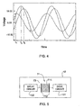
- Fig. 4 illustrates a schematic diagram of exemplary waveforms of three voltages activating three different code circuits 121 of a data carrier, resulting from a phase delay produced by the corresponding delay circuits 122.
- the waveforms of the activating voltages corresponding to these three different frequency responses, sequentially reach their maximum at times t 1 , t 2 and t 3 .
- all the code circuits 121 operate simultaneously, but can be recognized by a reader owing to both their different frequency responses and their sequential appearance.
- the phase behavior of the responses generated by the code circuits 121 is different, and therefore can be distinguished from each other and arranged in the order corresponding to the order of the symbols in the words.
- the delay circuit 122 can be either directly or indirectly coupled to the corresponding resonance circuit 121 for supplying voltage thereto.
- Fig. 5 illustrates a schematic view of the circuitry 12 in which a non-direct coupling of the delay circuit 122 to the corresponding code circuit 121 is implemented, according to one embodiment of the invention.
- a tunnel switch 71 based on a monolayer is arranged between the delay circuit 122 and the code circuit 121.
- the operation mechanism of the tunnel switch 71 is based on a known tunneling effect whereby electrons can move instantly through a thin insulator when a voltage of a certain amplitude is applied across the insulator.
- the tunnel switch 71 can include a monolayer of insulating high molecular weight material 711 placed between two conductive terminals 712 arranged in a lead 73 coupling the delay circuit 122 to the code circuit 121.
- FIG. 6B exemplary schematic diagrams of waveforms of activating voltages for activating three code circuits 121 are illustrated.
- Fig. 6B illustrates three pulses of the activating voltages obtained from the three waveforms shown in Fig. 6A by the tunnel switches 71 arranged downstream of the corresponding delay circuits 122. The fact that these three pulses are separated in time from each other implies that more definite time difference of the responses of the code circuits 121 can be obtained.
- tunnel switch 71 can operate also as a delay device.
- tunnel switch 71 Another property of the tunnel switch 71 is based on the fact that after it is subjected to a certain high voltage, it suffers electric breakdown and becomes always conductive. This process is irreversible, and the property can be utilized for the tags that require to be activated only once.
- the power unit (13 in Fig. 1A ) can include at least one coil printed on or incorporated in the substrate layer 11.
- the invention utilizes the property of the inductance coil to generate electromotive force (e.m.f.) for externally powering a data carrier.
- the power unit 13 may alternatively be a resonance circuit.
- the power unit is preferably operated at a frequency different from that of the power network and its harmonics.
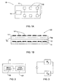
- FIGs. 7A-7D various examples of activation systems (magnetic field source) according to the invention for creating the changing magnetic flux d ⁇ d t required for activating the data carrier (10 in Fig. 1A or 100 in Fig. 1B ) are illustrated.
- a fixed magnetic assembly 111 of permanent magnet(s) is arranged in a place enclosing the route S of the data carrier movement in between the opposite poles of the magnet(s).
- the pennanent magnet(s) can be replaced by one or more DC electro-magnet.
- the vehicle (e.g., shopping cart) movement with a certain speed with respect to the magnetic field source can be implemented by providing a data carrier supporting stage driven for movement with respect to the magnetic field source along a data carrier containing site enclosed in between the magnets (i.e., within the magnetic field region).
- a data carrier supporting stage driven for movement with respect to the magnetic field source along a data carrier containing site enclosed in between the magnets (i.e., within the magnetic field region).
- the amount of e.m.f. voltage generated depends on (i) the strength of the magnetic field, (ii) the angle at which the coil cuts the magnetic field, (iii) the speed at which the data carrier is moved, and (iv) the area occupied by the coil within the magnetic field.
- the polarity of the e.m.f. voltage depends on the direction of the magnetic lines of flux and the direction of movement of the coil.
- two magnetic coils 112a and 112b extend along the opposite sides of a data carriers' containing site 120.
- the coils can either be accommodated within an exit gate of the store or be mounted on the cart itself.
- the pair of the coils 112a and 112b When operating, the pair of the coils 112a and 112b is activated by an AC current.
- the coils in turn, generate the changing magnetic flux required for generating e.m.f. in the power unit of the data carrier.
- a set of pairs of the coils 112a and 112b or DC electro-magnets can preferably be used.
- the entire data carrying site is simultaneously irradiated by the magnetic field, or the data carrier containing site is segmented by moving the magnetic field region from segment to segment of the data carrier containing site.
- all the coils may be operated simultaneously, or the coil-pairs may be sequentially operated to thereby sequentially create an AC magnetic field in successive regions of the data carriers' containing site. The same can be achieved by sequentially ON/OFF switching the successive DC electro-magnets.
- the site is mapped at every moment in time by a gradient of an alternating magnetic field.
- the different data carriers are activated sequentially and each data carrier, after being activated, launches a sequence of RF responses corresponding to the predetermined code pattern (word).
- a rotating magnetic field is produced within a data carrier' containing site 120 by using two or more magnets or coils - three such coils 113a-113c being shown in the present example.
- the rotating magnetic field can, for example, be obtained by mechanical rotation of permanent magnets or coils using a DC current.
- the rotating magnetic field can be obtained by a combination of coils in which alternating supply voltages are displaced in phases relative to each other.
- three coils 113a-113c are used, being arranged at an angle of 120 degrees.
- FIG. 8 shows a schematic view of a system for reading information stored in the data carrier of the present invention. It should be noted that the blocks in Fig. 8 are intended as functional entities only, such that the functional relationships between the entities are shown, rather than any physical connections and/or physical relationships.
- the data carrier 10 (or 100 of Fig. 1B ) is read by a reader arrangement formed by a magnetic field source 221 operable to actuate frequency responses of the data carrier (i.e., generated by the code circuits 121 ), an RF detector system 222 for detecting these responses and analyzing data indicative of the responses to identify the code pattern (word) stored in the data carrier.
- the detector system is composed of a single tunable resonance circuit or of an array of such circuits covering the predetermined frequency range, and operates for sensing the frequency responses of the code circuits and converting these responses into the predetermined information code, thereby determining the data stored in the data carrier.
- the converting of the frequency responses is performed on the basis of an appropriate algorithm establishing a relationship between the frequency responses, their difference in time-domain, and symbols of the information code.
- the data carrier, identification system and method of reading thereof were described in terms of a multi-symbol data carrier, the invention can be easily adapted for an article surveillance label.
- Such label can carry only single code circuit (i.e. one bit of information), and may be utilized, for example, for detecting the presence of the labels on or in an article.
- the surveillance label can be used in retail or library environments to deter theft or any other unauthorized removal of articles.
- the labels can be attached to articles designated to either be purchased or borrowed, and will trigger an alarm if carried without authorization through interrogation zones equipped with the corresponding system for reading the label.
- the data carrier of the present invention can actually be identified (triggered) by a reader tuned to the frequency of one of the RF circuits (code circuits) in the data carrier.
Landscapes
- Physics & Mathematics (AREA)
- Engineering & Computer Science (AREA)
- General Physics & Mathematics (AREA)
- Computer Security & Cryptography (AREA)
- Automation & Control Theory (AREA)
- Electromagnetism (AREA)
- Theoretical Computer Science (AREA)
- Textile Engineering (AREA)
- Signal Processing (AREA)
- Near-Field Transmission Systems (AREA)
- Radar Systems Or Details Thereof (AREA)
- Channel Selection Circuits, Automatic Tuning Circuits (AREA)
- Transceivers (AREA)
Applications Claiming Priority (2)
| Application Number | Priority Date | Filing Date | Title |
|---|---|---|---|
| US10/421,731 US6922146B2 (en) | 2003-04-24 | 2003-04-24 | Radio frequency data carrier and system for reading data stored therein |
| EP04723300A EP1618516B1 (de) | 2003-04-24 | 2004-03-25 | Radiofrequenzdatenträger und system zum lesen von darin gespeicherten daten |
Related Parent Applications (2)
| Application Number | Title | Priority Date | Filing Date |
|---|---|---|---|
| EP04723300.2 Division | 2004-03-25 | ||
| EP04723300A Division EP1618516B1 (de) | 2003-04-24 | 2004-03-25 | Radiofrequenzdatenträger und system zum lesen von darin gespeicherten daten |
Publications (2)
| Publication Number | Publication Date |
|---|---|
| EP2037397A2 true EP2037397A2 (de) | 2009-03-18 |
| EP2037397A3 EP2037397A3 (de) | 2011-07-06 |
Family
ID=33298738
Family Applications (2)
| Application Number | Title | Priority Date | Filing Date |
|---|---|---|---|
| EP08156795A Withdrawn EP2037397A3 (de) | 2003-04-24 | 2004-03-25 | System und Verfahren zum Lesen von auf einem Hochfrequenzdatenträger gespeicherten Daten |
| EP04723300A Expired - Lifetime EP1618516B1 (de) | 2003-04-24 | 2004-03-25 | Radiofrequenzdatenträger und system zum lesen von darin gespeicherten daten |
Family Applications After (1)
| Application Number | Title | Priority Date | Filing Date |
|---|---|---|---|
| EP04723300A Expired - Lifetime EP1618516B1 (de) | 2003-04-24 | 2004-03-25 | Radiofrequenzdatenträger und system zum lesen von darin gespeicherten daten |
Country Status (5)
| Country | Link |
|---|---|
| US (1) | US6922146B2 (de) |
| EP (2) | EP2037397A3 (de) |
| AT (1) | ATE417329T1 (de) |
| DE (1) | DE602004018300D1 (de) |
| WO (1) | WO2004095354A2 (de) |
Families Citing this family (18)
| Publication number | Priority date | Publication date | Assignee | Title |
|---|---|---|---|---|
| US20050068182A1 (en) * | 2003-09-30 | 2005-03-31 | Dunlap Richard L. | Application of radio frequency identification |
| US7498940B2 (en) | 2004-06-22 | 2009-03-03 | Vubiq, Inc. | RFID system utilizing parametric reradiated technology |
| US7284704B2 (en) * | 2004-06-28 | 2007-10-23 | International Barcode Corporation | Combined electromagnetic and optical communication system |
| US7549591B2 (en) * | 2004-06-28 | 2009-06-23 | International Barcode Corporation | Combined multi-frequency electromagnetic and optical communication system |
| US7506813B2 (en) * | 2005-01-06 | 2009-03-24 | Quad/Graphics, Inc. | Resonator use in the print field |
| US8425312B1 (en) | 2005-08-05 | 2013-04-23 | Electronicard Corp. | Playing card indentification system |
| US7796038B2 (en) * | 2006-06-12 | 2010-09-14 | Intelleflex Corporation | RFID sensor tag with manual modes and functions |
| US8830072B2 (en) * | 2006-06-12 | 2014-09-09 | Intelleflex Corporation | RF systems and methods for providing visual, tactile, and electronic indicators of an alarm condition |
| US8179231B1 (en) * | 2006-09-28 | 2012-05-15 | Louisiana Tech Research Foundation | Transmission delay based RFID tag |
| US7768457B2 (en) * | 2007-06-22 | 2010-08-03 | Vubiq, Inc. | Integrated antenna and chip package and method of manufacturing thereof |
| AU2008291469A1 (en) * | 2007-08-29 | 2009-03-05 | Dako Denmark A/S | On-site liquid production |
| US7793237B2 (en) * | 2007-12-17 | 2010-09-07 | International Business Machines Corporation | System, structure and method of providing dynamic optimization of integrated circuits using a non-contact method of selection, and a design structure |
| US9893406B2 (en) | 2009-08-19 | 2018-02-13 | Vubiq Networks, Inc. | Method of forming a waveguide interface by providing a mold to form a support block of the interface |
| EP2467897B1 (de) | 2009-08-19 | 2019-07-03 | Vubiq, Incorporated | Präzise wellenleiterschnittstelle |
| ITMI20121049A1 (it) * | 2012-06-18 | 2013-12-19 | Ab Medica Spa | Gabbia per cavie da laboratorio e metodo per l¿alimentazione senza fili di un dispositivo bioelettronico impiantato in una cavia |
| WO2015081109A1 (en) | 2013-11-26 | 2015-06-04 | Bayer Medical Care Inc. | System and method for medical fluid identification and verification |
| US10818997B2 (en) | 2017-12-29 | 2020-10-27 | Vubiq Networks, Inc. | Waveguide interface and printed circuit board launch transducer assembly and methods of use thereof |
| EP3891649A4 (de) | 2018-12-05 | 2022-08-24 | VUBIQ Networks, Inc. | Millimeterwellen-rfid-systeme mit hoher bit-dichte, vorrichtungen und verfahren zur verwendung davon |
Citations (10)
| Publication number | Priority date | Publication date | Assignee | Title |
|---|---|---|---|---|
| US5574470A (en) | 1994-09-30 | 1996-11-12 | Palomar Technologies Corporation | Radio frequency identification transponder apparatus and method |
| US5625341A (en) | 1995-08-31 | 1997-04-29 | Sensormatic Electronics Corporation | Multi-bit EAS marker powered by interrogation signal in the eight MHz band |
| US5682143A (en) | 1994-09-09 | 1997-10-28 | International Business Machines Corporation | Radio frequency identification tag |
| US5995006A (en) | 1995-09-05 | 1999-11-30 | Intermec Ip Corp. | Radio frequency tag |
| US6100804A (en) | 1998-10-29 | 2000-08-08 | Intecmec Ip Corp. | Radio frequency identification system |
| US6104311A (en) | 1996-08-26 | 2000-08-15 | Addison Technologies | Information storage and identification tag |
| US6304169B1 (en) | 1997-01-02 | 2001-10-16 | C. W. Over Solutions, Inc. | Inductor-capacitor resonant circuits and improved methods of using same |
| US6346884B1 (en) | 1998-09-25 | 2002-02-12 | Mitsubishi Materials Corporation | Apparatus for identifying an article |
| US6424263B1 (en) | 2000-12-01 | 2002-07-23 | Microchip Technology Incorporated | Radio frequency identification tag on a single layer substrate |
| US6441740B1 (en) | 1998-02-27 | 2002-08-27 | Intermec Ip Corp. | Radio frequency identification transponder having a reflector |
Family Cites Families (8)
| Publication number | Priority date | Publication date | Assignee | Title |
|---|---|---|---|---|
| US5604485A (en) * | 1993-04-21 | 1997-02-18 | Motorola Inc. | RF identification tag configurations and assemblies |
| US5444223A (en) | 1994-01-11 | 1995-08-22 | Blama; Michael J. | Radio frequency identification tag and method |
| US5446447A (en) * | 1994-02-16 | 1995-08-29 | Motorola, Inc. | RF tagging system including RF tags with variable frequency resonant circuits |
| EP0677752B1 (de) * | 1994-04-15 | 2001-06-27 | Siemens Aktiengesellschaft | Sensorsystem |
| US5680106A (en) * | 1995-10-27 | 1997-10-21 | International Business Machines Corporation | Multibit tag with stepwise variable frequencies |
| DE19860058C1 (de) * | 1998-12-23 | 2000-03-30 | Siemens Ag | Funkabfragbares Oberflächenwellen-Bauelement mit optimalem Codeumfang |
| DE19911369C2 (de) * | 1999-03-15 | 2003-04-03 | Nanotron Ges Fuer Mikrotechnik | Oberflächen-Wellen-Wandler-Einrichtung sowie Identifikationssystem hiermit |
| DE10052689A1 (de) | 2000-10-24 | 2002-05-02 | Metronom Indvermessung Gmbh | Kodierelement |
-
2003
- 2003-04-24 US US10/421,731 patent/US6922146B2/en not_active Expired - Fee Related
-
2004
- 2004-03-25 AT AT04723300T patent/ATE417329T1/de not_active IP Right Cessation
- 2004-03-25 EP EP08156795A patent/EP2037397A3/de not_active Withdrawn
- 2004-03-25 WO PCT/IL2004/000270 patent/WO2004095354A2/en not_active Ceased
- 2004-03-25 EP EP04723300A patent/EP1618516B1/de not_active Expired - Lifetime
- 2004-03-25 DE DE602004018300T patent/DE602004018300D1/de not_active Expired - Lifetime
Patent Citations (10)
| Publication number | Priority date | Publication date | Assignee | Title |
|---|---|---|---|---|
| US5682143A (en) | 1994-09-09 | 1997-10-28 | International Business Machines Corporation | Radio frequency identification tag |
| US5574470A (en) | 1994-09-30 | 1996-11-12 | Palomar Technologies Corporation | Radio frequency identification transponder apparatus and method |
| US5625341A (en) | 1995-08-31 | 1997-04-29 | Sensormatic Electronics Corporation | Multi-bit EAS marker powered by interrogation signal in the eight MHz band |
| US5995006A (en) | 1995-09-05 | 1999-11-30 | Intermec Ip Corp. | Radio frequency tag |
| US6104311A (en) | 1996-08-26 | 2000-08-15 | Addison Technologies | Information storage and identification tag |
| US6304169B1 (en) | 1997-01-02 | 2001-10-16 | C. W. Over Solutions, Inc. | Inductor-capacitor resonant circuits and improved methods of using same |
| US6441740B1 (en) | 1998-02-27 | 2002-08-27 | Intermec Ip Corp. | Radio frequency identification transponder having a reflector |
| US6346884B1 (en) | 1998-09-25 | 2002-02-12 | Mitsubishi Materials Corporation | Apparatus for identifying an article |
| US6100804A (en) | 1998-10-29 | 2000-08-08 | Intecmec Ip Corp. | Radio frequency identification system |
| US6424263B1 (en) | 2000-12-01 | 2002-07-23 | Microchip Technology Incorporated | Radio frequency identification tag on a single layer substrate |
Non-Patent Citations (1)
| Title |
|---|
| VINCETT, THIN SOLID FILMS, vol. 68, 1980, pages 135 - 171 |
Also Published As
| Publication number | Publication date |
|---|---|
| EP1618516B1 (de) | 2008-12-10 |
| EP1618516A2 (de) | 2006-01-25 |
| US20040211840A1 (en) | 2004-10-28 |
| WO2004095354A3 (en) | 2005-02-10 |
| EP2037397A3 (de) | 2011-07-06 |
| DE602004018300D1 (de) | 2009-01-22 |
| US6922146B2 (en) | 2005-07-26 |
| WO2004095354A2 (en) | 2004-11-04 |
| ATE417329T1 (de) | 2008-12-15 |
Similar Documents
| Publication | Publication Date | Title |
|---|---|---|
| EP1618516B1 (de) | Radiofrequenzdatenträger und system zum lesen von darin gespeicherten daten | |
| TW316298B (en) | Concealed magnetic ID code and antitheft tag | |
| AU716803B2 (en) | Spatial magnetic interrogation | |
| US6894614B2 (en) | Radio frequency detection and identification system | |
| US7095311B2 (en) | Identification coding schemes for modulated reflectance systems | |
| US8167204B2 (en) | Wireless damage location sensing system | |
| AU2001261192A1 (en) | Radio frequency detection and identification system | |
| CN107636743B (zh) | Rfid和/或rfid/em防盗射频检测装置 | |
| EP1183661B1 (de) | Etikett zur elektronischen artikelidentifizierung, verfahren zur kodierung einesidentitätskodes auf solchem etikett und vorrichtung zur identifizierung desselben | |
| GB2322048A (en) | Circuit for Interrogating Magnetic Tags | |
| AU738833B2 (en) | Apparatus for interrogating magnetic tags | |
| AU738801B2 (en) | Magnetic coding of articles | |
| US11059647B2 (en) | Apparatus, systems and methods for identifying products | |
| JPH1185940A (ja) | 無線通信端末及びそのセキュリティ方法 | |
| CA2320670C (en) | Apparatus for interrogating magnetic tags | |
| AU2338000A (en) | An article identification tag, and a method for the detection thereof | |
| WO2002056246A1 (en) | Programmable tags | |
| JP2006139617A (ja) | 共振機能付チューブフィルム及び共振機能付容器 |
Legal Events
| Date | Code | Title | Description |
|---|---|---|---|
| PUAI | Public reference made under article 153(3) epc to a published international application that has entered the european phase |
Free format text: ORIGINAL CODE: 0009012 |
|
| AC | Divisional application: reference to earlier application |
Ref document number: 1618516 Country of ref document: EP Kind code of ref document: P |
|
| AK | Designated contracting states |
Kind code of ref document: A2 Designated state(s): AT BE BG CH CY CZ DE DK EE ES FI FR GB GR HU IE IT LI LU MC NL PL PT RO SE SI SK TR |
|
| AX | Request for extension of the european patent |
Extension state: AL LT LV MK |
|
| PUAL | Search report despatched |
Free format text: ORIGINAL CODE: 0009013 |
|
| AK | Designated contracting states |
Kind code of ref document: A3 Designated state(s): AT BE BG CH CY CZ DE DK EE ES FI FR GB GR HU IE IT LI LU MC NL PL PT RO SE SI SK TR |
|
| AX | Request for extension of the european patent |
Extension state: AL LT LV MK |
|
| AKY | No designation fees paid | ||
| REG | Reference to a national code |
Ref country code: DE Ref legal event code: R108 Effective date: 20120314 |
|
| STAA | Information on the status of an ep patent application or granted ep patent |
Free format text: STATUS: THE APPLICATION IS DEEMED TO BE WITHDRAWN |
|
| 18D | Application deemed to be withdrawn |
Effective date: 20120110 |