EP2037172A2 - Gas turbine manager furnace with fuel nozzle with controlled fuel homogeneity - Google Patents
Gas turbine manager furnace with fuel nozzle with controlled fuel homogeneity Download PDFInfo
- Publication number
- EP2037172A2 EP2037172A2 EP08015722A EP08015722A EP2037172A2 EP 2037172 A2 EP2037172 A2 EP 2037172A2 EP 08015722 A EP08015722 A EP 08015722A EP 08015722 A EP08015722 A EP 08015722A EP 2037172 A2 EP2037172 A2 EP 2037172A2
- Authority
- EP
- European Patent Office
- Prior art keywords
- fuel
- der
- gasturbinenmagerbrenner
- gas turbine
- burner
- Prior art date
- Legal status (The legal status is an assumption and is not a legal conclusion. Google has not performed a legal analysis and makes no representation as to the accuracy of the status listed.)
- Granted
Links
Images


Classifications
-
- F—MECHANICAL ENGINEERING; LIGHTING; HEATING; WEAPONS; BLASTING
- F23—COMBUSTION APPARATUS; COMBUSTION PROCESSES
- F23D—BURNERS
- F23D11/00—Burners using a direct spraying action of liquid droplets or vaporised liquid into the combustion space
- F23D11/10—Burners using a direct spraying action of liquid droplets or vaporised liquid into the combustion space the spraying being induced by a gaseous medium, e.g. water vapour
- F23D11/106—Burners using a direct spraying action of liquid droplets or vaporised liquid into the combustion space the spraying being induced by a gaseous medium, e.g. water vapour medium and fuel meeting at the burner outlet
- F23D11/107—Burners using a direct spraying action of liquid droplets or vaporised liquid into the combustion space the spraying being induced by a gaseous medium, e.g. water vapour medium and fuel meeting at the burner outlet at least one of both being subjected to a swirling motion
-
- F—MECHANICAL ENGINEERING; LIGHTING; HEATING; WEAPONS; BLASTING
- F23—COMBUSTION APPARATUS; COMBUSTION PROCESSES
- F23R—GENERATING COMBUSTION PRODUCTS OF HIGH PRESSURE OR HIGH VELOCITY, e.g. GAS-TURBINE COMBUSTION CHAMBERS
- F23R3/00—Continuous combustion chambers using liquid or gaseous fuel
- F23R3/28—Continuous combustion chambers using liquid or gaseous fuel characterised by the fuel supply
- F23R3/34—Feeding into different combustion zones
- F23R3/343—Pilot flames, i.e. fuel nozzles or injectors using only a very small proportion of the total fuel to insure continuous combustion
Definitions
- the invention relates to a gas turbine lean burn burner according to the features of the preamble of claim 1.
- the invention relates to a fuel nozzle with controlled fuel inhomogeneity, which provides the opportunity to introduce the fuel in an optimal manner for combustion.
- the main stage of the known so-called lean burners is often designed as a so-called film depositor ( US 2006/0248898 A1 ).
- some injection methods with single-jet injection are known which are intended to ensure a high degree of homogenization of the initial fuel distribution and / or a high penetration depth of the injected fuel ( US 2004/0040311 A1 ).
- bluff body geometries which may be designed as baffle plates or V-shaped stabilizers arranged (eg US 4445339 and WO 10/860659 ).
- the local fuel-air mixture is not controlled adjustable.
- the problem is that with a desired homogeneous axial and circumferential loading of the fuel on the film layer
- a very good air-fuel mixture with average low combustion temperatures and thus low NOx emissions can be achieved, however the homogeneous mixture formation aimed at under high load conditions under partial load conditions as a result of insufficient fuel loading on the film former lead to a significant deterioration of the combustion chamber burnout (cf. Fig. 6 ).
- the background is the reduced heat release associated with lean mixtures as well as the property for local flame extinction with successive reduction of the fuel and low combustion chamber pressure and temperature.
- Another flow form is characterized by a so-called "unfolding" of the flow and the formation of a recirculation area on the burner axis (see Fig. 4 ).
- an attenuated recirculation area in the wake of the stabilizer is additionally present in this variant of the flame stabilizer.
- the invention has for its object to provide a Gasturbinenmagerbrenner of the type mentioned, which has a low structure while avoiding the disadvantages of the prior art low pollutant emissions, improved flame stability and a high Brennttingausbrand.
- a burner operated with excess air having a pilot 17 and a main fuel injection 18.
- the aim is to set a targeted inhomogeneity of the fuel-air mixture.
- the goal is to create a load-dependent variation of fuel placement in the main stage of the fuel in order to influence the degree of local fuel-air mixture.
- the background is that a high mixture homogenization on the one hand favors the formation of low NOx emissions, on the other hand, a reduced mixture homogenization by targeted formation of locally rich mixture zones advantageous for achieving a high burnout of the combustion chamber, especially at partial load conditions.
- the partially competing properties are to be optimized by the method of load-dependent fuel inhomogeneity.
- the burner is characterized by a novel flame stabilizer between the inner and middle flow channel, which should lead to improved flow control within the combustion chamber, in particular with regard to the interaction of the pilot and main flow in addition to the method for local load-dependent fuel enrichment.
- An essential feature of the present invention is that the outlet openings of the discrete fuel injections are set in the circumferential direction ( see FIGS. 10, 12 ).
- the angle of attack of the fuel jets in the circumferential direction should be in the range between 10 ° ⁇ ⁇ 2 ⁇ 60 °. This can be by a - in relation to the twisted air flow of the central air passage 15 - the same direction or opposite directions.
- the fuel jets may be at individual angles ⁇ 2.
- the fuel jets can continue to be employed with respect to the burner axis 4 in the axial direction.
- the preferred axial angle of attack of the fuel jets is in the range between -10 ° ⁇ ⁇ 1 ⁇ 90 °.
- the fuel jets can be set at individual angles ⁇ 1.
- the recesses can also be made individually (both with respect to ⁇ 1 and ⁇ 2).
- the first method is to meter the main fuel through discrete fuel bores upstream of the main fuel passage exit face and directly adjust a circumferentially controlled inhomogeneous fuel-air mixture. This can be achieved by a suitable choice of the number, arrangement and adjustment of the fuel bores and by ensuring a low interaction of the injected fuel jets with the wall element already described within the fuel level. This means that the fuel jets injected into the middle flow channel still have a defined velocity pulse.
- the short run length of the main fuel between the inner surface of the main stage 19, 38 and the location of the holes 41 is a load-dependent penetration depth of a more or less closed fuel film, albeit reduced or to a fuel film approximated fuel entry adjustable.
- a "subsequent" local enrichment of the fuel film in the circumferential direction is proposed when using a fuel film ( Fig. 19 ).
- These inhomogeneities in the fuel distribution can be achieved by different measures, for example of turbulators placed on the film laying surface, a suitable design of the trailing edge of the film layer (eg corrugated arrangement, lamella shape).
- the said methods for local adjustment of inhomogeneities for the fuel film can be located both within the middle flow channel both upstream and / or downstream of the film gap.
- turbulators on the surface of the film layer as follows: upstream or downstream of the film gap, then each 1-row or multi-row, with / without circumferential position, but also a circumferentially closed ring geometry of the turbulator (eg circumferential edge / step).
- a specific contouring, both in the axial and in the circumferential direction, of the flame stabilizer is proposed.
- An embodiment with a flower-shaped geometry for the outlet cross-section of a flame stabilizer is in Fig. 14 shown.
- the diameter of the exit surface varies between a minimum diameter A1, which can lead to a pronounced decentralized recirculation in the wake of the V-shaped flame stabilizer, and a maximum diameter A2, which favors the formation of a central recirculation on the burner axis.
- a minimum diameter A1 which can lead to a pronounced decentralized recirculation in the wake of the V-shaped flame stabilizer
- a maximum diameter A2 which favors the formation of a central recirculation on the burner axis.
- Fig. 14 illustrated variant for a contoured flame stabilizer with 8 so-called “flowers” are proposed further variants, the proposed geometries between 2 and 20 "flowers” may have.
- Fig. 15 Another version is shown for a slightly more contoured flame stabilizer with 8 "flowers” in which the diameter A1 is reduced and at the same time the diameter A2 is increased.
- the flow locally undergoes a flow acceleration or delay, resulting in a highly three-dimensional flow area with both centralized and decentralized recirculation (see Fig. 5 ).
- a further embodiment provides for the circumferential alignment of the 3D wave geometry (contours) of the flame stabilizer at the effective helix angle of the deflected air flow for the inner pilot stage and / or the effective helix angle of the deflected air flow for the radially outer main stage.
- Fig. 16 another embodiment of the contoured flame stabilizer is shown.
- the contouring of the inner leg of the flame holder has 5 flowers, whereby by the number and arrangement of the flowers a diameter variation is achieved with a controlled asymmetry in the flow guidance of the pilot flow.
- both a strong flow acceleration as well as due to the cross-sectional widening a deflection and flow delay is implemented in a sectional plane.
- Fig. 17 another embodiment of a flame stabilizer with an eccentric positioning shown.
- An additional option for contouring 25 is a sawtooth profile.
- bimetal elements can be integrated into the front part of the flame stabilizer or at the trailing edge of the flame stabilizer to achieve a desired change in exit geometry.
- Another advantage of the invention is the possibility of controlled adjustment of a "mixed" flow field with distinct central and decentralized recirculation areas. It is expected that the presence of a central recirculation on the one hand, the NOx emissions can be significantly reduced and can be achieved by setting a sufficient sudströmzone in the wake of the flame stabilizer very high flame stability against lean burn. Furthermore, it is expected that the interaction between the pilot and main flame can be more controlled, since depending on the 3D contour of the flame stabilizer there is the possibility to generate different flow states with more or less strong interaction of the pilot and main flow. With the help of this targeted generation of a "mixed" flow form, the operating range of the lean burn burner can be significantly extended between low and full load.
- Another advantage of the invention is expected in the field of ignition of the pilot stage. Due to the contoured geometry of the exit surface with locally increased pitch diameters A2, a radial expansion (dispersion) of the pilot spray is generated, which can lead to improved mixture preparation. This increases the likelihood that a greater part of the pilot spray can be brought into the vicinity of the combustion chamber wall in the region of the spark plug and thus - depending on the local fuel-air mixture - the ignition characteristics of the burner can be improved.
- Another advantage of the three-dimensional contouring of the flame stabilizer is an equalization of the flow and thus the reduction of the occurrence of possible flow instabilities, which can often form in the wake of bluff bodies - especially in the shear layer.
Landscapes
- Engineering & Computer Science (AREA)
- Chemical & Material Sciences (AREA)
- Combustion & Propulsion (AREA)
- Mechanical Engineering (AREA)
- General Engineering & Computer Science (AREA)
- Pre-Mixing And Non-Premixing Gas Burner (AREA)
Abstract
Description
Die Erfindung bezieht sich auf einen Gasturbinenmagerbrenner gemäß den Merkmalen des Oberbegriffs des Anspruchs 1.The invention relates to a gas turbine lean burn burner according to the features of the preamble of
Im Einzelnen bezieht sich die Erfindung auf eine Kraftstoffdüse mit kontrollierter Kraftstoffinhomogenität, welche die Möglichkeit schafft, den Kraftstoff in für die Verbrennung optimaler Weise einzubringen.In particular, the invention relates to a fuel nozzle with controlled fuel inhomogeneity, which provides the opportunity to introduce the fuel in an optimal manner for combustion.
Zur Senkung der thermisch bedingten Stickoxidemissionen sind unterschiedliche Konzepte für Brennstoffdüsen bekannt. Eine Möglichkeit besteht in dem Betrieb von Brennern mit einem hohen Luft-Brennstoff-Überschuss. Hier wird das Prinzip ausgenutzt, dass infolge eines mageren Gemisches und bei gleichzeitiger Gewährleistung einer ausreichenden räumlichen Homogenität des Kraftstoff-Luft-Gemisches eine Senkung der Verbrennungstemperaturen und damit der thermisch bedingten Stickoxide ermöglicht wird. Bei vielen derartigen Brennern wird zudem eine sogenannte interne Kraftstoffstufung angewendet. Dies bedeutet, dass neben einer für niedrige NOx-Emissionen ausgelegte Hauptkraftstoffeinspritzung noch eine sogenannte Pilotstufe in den Brenner integriert ist, die mit einem erhöhten Kraftstoff-Luft-Anteil betrieben wird und die Stabilität der Verbrennung, einen ausreichenden Brennkammerausbrand sowie ausreichende Zündeigenschaften gewährleisten soll (siehe
Ein weiteres Merkmal bekannter Brenner ist das Vorhandensein von sogenannten Stabilisatorelementen, die zur Stabilisierung von Flammen in Brennkammern verwendet werden (siehe
Für die bekannten Brennerkonzepte ist die lokale Kraftstoff-Luft-Mischung nicht kontrolliert einstellbar. Insbesondere bei den bereits angesprochenen Filmlegerkonzepten besteht das Problem, dass mit einer angestrebten homogenen axialen und umfangsmäßigen Beladung des Kraftstoffs auf dem Filmleger zwar eine sehr gute Kraftstoff-Luft-Mischung mit im Mittel niedrigen Verbrennungstemperaturen und damit niedrigen NOx-Emissionen erreicht werden kann, allerdings kann die für Hochlastbedingungen angestrebte homogene Gemischbildung bei Teillastbedingungen infolge einer ungenügenden Kraftstoffbeladung auf dem Filmleger zu einer deutlichen Verschlechterung des Brennkammerausbrandes führen (siehe
Auch hinsichtlich der Flammenverankerung mittels der bekannten Stabilisatoren sind Nachteile vorhanden. Allgemein lässt sich über die Dimension des Flammenhalters, wie z.B. den äußeren Durchmesser und den Widerstandsbeiwert der Strömungsblockage, eine Einstellung der Größe der Rezirkulation im Nachlauf des Stabilisators erzielen. Eine Anwendung für einen Flammenhalter für einen schadstoffarmen Magerbrenner ist z.B. aus (
Als Stand der Technik ist weiterhin auf die
Eine andere Strömungsform zeichnet sich durch ein sog. "Aufklappen" der Strömung und der Ausbildung eines Rezirkulationsgebietes auf der Brennerachse aus (siehe
Aus den beschriebenen Effekten ist zu erkennen, dass mit den bisher bekannten Flammenstabilisatorgeometrien nur eine spezifische Strömungsform einstellbar ist, die jedoch nur zur Verbesserung einiger Betriebsparameter, wie z.B. der Magerverlöschstabilität beiträgt, während gleichzeitig eine Verschlechterung anderer Betriebsparameter, wie z.B. der Ruß- und NOx-Emissionen, zu beobachten ist.It can be seen from the effects described that with the previously known flame stabilizer geometries only a specific flow shape can be set, which, however, can only be adjusted to improve some operating parameters, e.g. contributes to the poor extinguishing stability while at the same time reducing the deterioration of other operating parameters, e.g. soot and NOx emissions.
Der Erfindung liegt die Aufgabe zugrunde, einen Gasturbinenmagerbrenner der eingangs genannten Art zu schaffen, welcher bei einfachem Aufbau unter Vermeidung der Nachteile des Standes der Technik geringe Schadstoffemissionen, eine verbesserte Flammenstabilität und einen hohen Brennkammerausbrand aufweist.The invention has for its object to provide a Gasturbinenmagerbrenner of the type mentioned, which has a low structure while avoiding the disadvantages of the prior art low pollutant emissions, improved flame stability and a high Brennkammerausbrand.
Erfindungsgemäß wird die Aufgabe durch Merkmalskombination des Anspruchs 1 gelöst. Die Unteransprüche zeigen weitere vorteilhafte Ausgestaltungen der erfindungsgemäßen Lösung.According to the invention the object is achieved by combination of features of
Im Folgenden wird die Erfindung anhand von Ausführungsbeispielen in Verbindung mit der Zeichnung beschrieben. Dabei zeigt:
- Fig. 1:
- Stand der Technik, Brenner für eine Fluggasturbine (
US 6 543 235 B1 - Fig. 2:
- Stand der Technik, Beispiel eines konventionell ausgebildeten Flammenstabilisators mit V-Form Geo- metrie (
US 6 272 840 B1 - Fig. 3:
- Stand der Technik, Berechnete Strömungsform in Abhängigkeit vom Austrittsdurchmesser des inneren Schenkels des Flammenstabilisators, Beispiel für eine Brennkammerströmung mit ausgeprägter dezentra- ler Rezirkulation im Nachlauf des Flammenstabilisa- tors infolge eines kleinen Austrittsdurchmessers A = A1;
- Fig. 4:
- Stand der Technik, Berechnete Strömungsform in Abhängigkeit vom Austrittsdurchmesser des inneren Schenkels des Flammenstabilisators, Beispiel für eine Brennkammerströmung mit zentraler Rezirkulation und deutlich verkleinertem Rezirkulationsgebiet im Nachlauf des Flammenstabilisators infolge eines ver- größerten Austrittsdurchmessers A = A2;
- Fig. 5:
- Berechnete "gemischte" Strömungsform mit zentraler Rezirkulation sowie ausgeprägter dezentraler Rezir- kulation im Nachlauf eines konturierten Flammensta- bilisators infolge eines im Umfang veränderlichen Austrittsdurchmessers des Flammenstabilisators A1 < A ≤ A2;
- Fig. 6:
- Brennkammerausbrand vs. Brennstoffanteil des Pilot- brenners, Schematische Darstellung des Ausbrandver- haltens für einen Filmleger sowie für eine diskrete Kraftstoffstrahleindüsung für die Hauptstufe des Ma- gerbrenners bei Teillastbedingungen;
- Fig. 7:
- Hauptkomponenten für den erfindungsgemäßen Magerbrenner, Ausführungsvariante mit diskretem Kraftstoffeintrag des Hauptkraftstoffs über Einzel- bohrungen an der inneren Oberfläche der Hauptkraft- stoffeinspritzung sowie mit blütenförmiger Geometrie für den inneren Schenkel des Flammenstabilisators;
- Fig. 8:
- Hauptkomponenten für den erfindungsgemäßen Magerbrenner, Ausführungsvariante mit diskretem Kraftstoffeintrag des Hauptkraftstoffs über einen Filmspalt an der inneren Oberfläche der Hauptkraft- stoffeinspritzung sowie mit blütenförmiger Geometrie für den inneren Schenkel des Flammenstabilisators;
- Fig. 9:
- Berechnete Umfangsverteilung der Kraftstoff-Luft- Verteilung im Nachlauf der Hauptkraftstoffeinsprit- zung des Brenners: Ausführungsform mit gezielter In- homogenität des Kraftstoffeintrags durch angestellte diskrete Kraftstoffbohrungen (Beispiel, n = 24);
- Fig. 10:
- Hauptstufe des erfindungsgemäßen Brenners: Darstel- lung der berechneten Strahleindringung in den mitt- leren Strömungskanal;
- Fig. 11:
- Ausführungsvariante des erfindungsgemäßen Brenners mit Darstellung der Anstellung der Kraftstoffbohrun- gen in axialer Richtung δ1 sowie Anstellung der inne- ren stromabseitigen Oberfläche der Hauptkraftstoff- einspritzung β;
- Fig. 12:
- Ausführungsvariante des erfindungsgemäßen Brenners mit Darstellung der Anstellung der Kraftstoffbohrun- gen in Umfangsrichtung δ2;
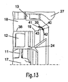
- Fig. 13:
- Ausführungsvariante des erfindungsgemäßen Brenners mit filmartiger Platzierung des Hauptkraftstoffs mit lokalen Kraftstoffanreicherungen, schematische Dar- stellung der stromaufseitigen Zumessung des Haupt- kraftstoffs über Einzelbohrungen;
- Fig. 14:
- Ausführungsform für einen Flammenstabilisator mit Konturierung der Austrittsgeometrie des inneren Schenkels, blütenförmige Geometrie;
- Fig. 15:
- Weitere Ausführungsform für einen Flammenstabilisa- tor mit stärkerer Konturierung der Austrittsgeomet- rie des inneren Schenkels, blütenförmige Geometrie;
- Fig. 16:
- Weitere Ausführungsform für einen Flammenstabilisa- tor mit Konturierung der Austrittsgeometrie des in- neren Schenkels, blütenförmige Geometrie mit gegenü- berliegender asymmetrischer Variation des Austritts- durchmessers;
- Fig. 17:
- Weitere Ausführungsform für einen Flammenstabilisa- tor mit Konturierung der Austrittsgeometrie des in- neren Schenkels, exzentrische Austrittsgeometrie;
- Fig. 18:
- Ausführungsform für einen Flammenstabilisator mit variabler Austrittsgeometrie, Darstellung von Posi- tionierungsmöglichkeiten von variablen Geometrieelementen (z.B. Piezo- oder Bi-Metall-Ele- mente) in den unteren und oberen Schenkel des Flam- menstabilisators, und
- Fig. 19:
- eine Ausführungsvariante des erfindungsgemäßen Bren- ners mit filmartiger Platzierung des Hauptkraft- stoffs mit lokalen Kraftstoffanreicherungen durch Turbulatoren stromab des Filmspalts.
- Fig. 1:
- Prior art burner for an aircraft gas turbine (
US Pat. No. 6,543,235 B1 - Fig. 2:
- State of the art, example of a conventionally designed flame stabilizer with V-shape geometry (
US Pat. No. 6,272,840 B1 - 3:
- PRIOR ART, Calculated flow shape as a function of the exit diameter of the inner leg of the flame stabilizer, example of a combustion chamber flow with pronounced decentralized recirculation in the wake of the flame stabilizer as a result of a small exit diameter A = A1;
- 4:
- PRIOR ART, Calculated flow shape as a function of the exit diameter of the inner leg of the flame stabilizer, example of a combustion chamber flow with central recirculation and clearly reduced recirculation area in the wake of the flame stabilizer as a result of an increased exit diameter A = A2;
- Fig. 5:
- Calculated "mixed" flow regime with central recirculation and pronounced decentralized recirculation in the wake of a contoured flame stabilizer due to a variable diameter exit diameter of the flame stabilizer A1 < A ≤ A2;
- Fig. 6:
- Combustion burnout vs. Fuel fraction of the pilot burner, Schematic representation of the burn-out behavior for a film lay- er as well as a discrete fuel-jet injection for the main stage of the fuel burner under partial load conditions;
- Fig. 7:
- Main components for the lean burn burner according to the invention, embodiment variant with discrete fuel input of the main fuel via individual bores on the inner surface of the main fuel injection and with flower-shaped geometry for the inner leg of the flame stabilizer;
- Fig. 8:
- Main components for the lean burn burner according to the invention, embodiment variant with discrete fuel input of the main fuel over a film gap on the inner surface of the main fuel injection and with flower-shaped geometry for the inner leg of the flame stabilizer;
- Fig. 9:
- Calculated circumferential distribution of the fuel-air distribution in the wake of the main fuel injection of the burner: embodiment with targeted inhomogeneity of the fuel input by employed discrete fuel bores (example, n = 24);
- Fig. 10:
- Main stage of the burner according to the invention: depiction of the calculated jet penetration into the central flow channel;
- Fig. 11:
- Embodiment variant of the burner according to the invention with representation of the setting of the fuel bores in the axial direction δ1 and employment of the inner downstream surface of the main fuel injection β;
- Fig. 12:
- Embodiment variant of the burner according to the invention with representation of the employment of fuel bores in the circumferential direction δ2;
- Fig. 13:
- Embodiment variant of the burner according to the invention with film-like placement of the main fuel with local fuel enrichments, schematic representation of the upstream metering of the main fuel via individual bores;
- Fig. 14:
- Embodiment for a flame stabilizer with contouring of the exit geometry of the inner leg, flower-shaped geometry;
- Fig. 15:
- Further embodiment for a flame stabilizer with more pronounced contouring of the exit geometry of the inner leg, flower-shaped geometry;
- Fig. 16:
- Further embodiment for a flame stabilizer with contouring of the outlet geometry of the inner leg, flower-shaped geometry with opposite asymmetrical variation of the outlet diameter;
- Fig. 17:
- Further embodiment for a flame stabilizer with contouring of the exit geometry of the inner leg, eccentric exit geometry;
- Fig. 18:
- Embodiment for a flame stabilizer with variable exit geometry, representation of possible positioning of variable geometry elements (eg piezo or bimetallic elements) in the lower and upper limb of the flame stabilizer, and
- Fig. 19:
- an embodiment variant of the burner according to the invention with film-like placement of the main fuel with local fuel enrichments by turbulators downstream of the film gap.
Erfindungsgemäß ist ein mit Luftüberschuss betriebener Brenner (siehe
Kontrollierte Kraftstoffinhomogenität durch eine diskrete Strahleindüsung:
- Als bevorzugte Methode zur Einstellung von lokalen Kraftstoffinhomogenitäten wird eine diskrete Strahleindüsung über mehrere Kraftstoffbohrungen n für die Hauptstufe eines Magerbrenners vorgeschlagen. Vorzugsweise sind zwischen n = 8 und n = 40 Bohrungen vorgesehen. Die Bohrungen können dabei gleichmäßig als auch ungleichmäßig im Umfang verteilt sein. Weiterhin ist eine einreihige als auch mehrreihige sowie gestaffelte Anordnung der Bohrungen möglich. Über geeignete konstruktive Maßnahmen kann eine kontrollierte Einstellung der Eindringtiefe der diskreten Kraftstoffstrahlen und damit der Güte der lokalen Kraftstoff-Luft-Mischung erreicht werden. Der größte Druckabfall in der Hauptkraftstoffleitung und damit der die Zumessung des Kraftstoffs bestimmende Querschnitt befindet sich an bzw. in der Nähe der inneren Oberfläche der Hauptstufe 19. Die diskrete Eindüsung des Kraftstoffs über Bohrungen erfolgt unter einem bestimmten Winkel zur Brennerachse radial nach innen in
den mittleren Strömungskanal 15. Die Eindüsung des Kraftstoffs der Hauptstufe kann dabei sowohl an der stromauf- als auch stromabseitigen Oberfläche der Hauptkraftstoffeinspritzung erfolgen 38, 19. Die vorgeschlagene Methode der diskreten Strahleindüsung für die Hauptstufe eines Magerbrenners zeichnet sich durch eine lastabhängige Eindringtiefe der diskreten Strahlen aus. Bei niedrigen bis mittleren Betriebsbedingungen, bei der die Hauptstufe zur Gewährleistung verringerter NOx- und Ruß-Emissionen zusätzlich zur Pilotstufe zugeschaltet wird, ist infolge des verringerten Kraftstoffdrucks - und damit infolge eines niedrigen Kraftstoff-Luft-Impulsverhältnisses - die Eindringtiefe der diskreten Kraftstoffstrahlen gering. Bei höheren Lastbedingungen steigt das Kraftstoff-Luft-Impulsverhältnis deutlich an und führt zu einem tieferen Eindringen der Kraftstoffstrahlen in den mittleren Strömungskanal.
- As a preferred method for adjusting local fuel inhomogeneities, a discrete jet injection over a plurality of fuel wells n for the main stage of a lean burn burner is proposed. Preferably, between n = 8 and n = 40 holes are provided. The holes can be distributed evenly as well as unevenly around the circumference. Furthermore, a single-row and multi-row and staggered arrangement of the holes is possible. By appropriate design measures, a controlled adjustment of the penetration depth of the discrete fuel jets and thus the quality of the local fuel-air mixture can be achieved. The largest pressure drop in the main fuel line and thus the metering of the fuel defining cross section is located at or in the vicinity of the inner surface of the
main stage 19. The discrete injection of the fuel through holes is carried out at a certain angle to the burner axis radially in themiddle flow channel 15. The injection of the fuel of the main stage can take place both at the upstream and downstream surface of themain fuel injection
Ein wesentliches Merkmal der vorliegenden Erfindung ist, dass die Austrittsöffnungen der diskreten Kraftstoffeindüsungen in Umfangsrichtung angestellt sind (
Bei niedrigen bis mittleren Lastbedingungen führen die beschriebenen Effekte vor allem zu einer Verbesserung des Brennkammerausbrandes infolge lokaler Kraftstoffanreicherung. Bei höheren Lastbedingungen bis zu Volllastbedingungen stellt sich durch einen höheren Kraftstoffdruck und damit auch höherer Kraftstoffgeschwindigkeit der Einzelstrahlen eine größere Eindringtiefe der Strahlen ein. Die damit verbundene Intensivierung der Strahldispersion führt bei gegebener Umfangsanstellung der Kraftstoffstrahlen zu einer weiteren Vergleichmäßigung der Kraftstoff-Luft-Mischung in radialer Richtung und Umfangsrichtung. Mit dieser Methode der starken Anstellung der Kraftstoffstrahlen δ1, δ2 lassen sich bei Hochlastbedingungen magere Kraftstoff-Luft-Verhältnisse einstellen.At low to medium load conditions, the effects described above lead to an improvement of the combustion chamber burnout as a result of local fuel enrichment. At higher load conditions up to full load conditions, a higher penetration depth of the jets arises due to a higher fuel pressure and thus also higher fuel speed of the individual jets. The associated intensification of the jet dispersion results in a given circumferential adjustment of the fuel jets to a further homogenization of the fuel-air mixture in the radial direction and circumferential direction. With this method of the strong employment of the fuel jets δ1, δ2 can be set under high load conditions lean air-fuel ratios.
Kontrollierte Kraftstoffinhomogenität durch einen Kraftstofffilm mit lokalen Kraftstoffanreicherungen:
- In
Fig. 9 ist in einer Querschnittsdarstellung eine berechnete Umfangsverteilung der Kraftstoff-Luft-Mischung für die Anwendung von stark angestellten Kraftstoffstrahlen für die Hauptstufe gezeigt. Es sind lokal magere Gemische 32 sowie im Bereich der Strahleindringung in den mittleren Strömungskanallokal kraftstoffangereicherte Zonen 31 zu erkennen. Neben der Zumessung des Kraftstoffs über Bohrungen an oder nahe der Oberfläche der Hauptkraftstoffeinspritzung 38, 19 besteht ein weiteres Merkmal der vorliegenden Erfindung in der Zumessung des Kraftstoffs für die Hauptstufe weiter stromauf in der Kraftstoffpassage. Eine gegenüber der diskreten Kraftstoffeindüsung für die Hauptstufe geänderte Kraftstoffplatzierung über einen Filmspalt im Austritt der Kraftstoffpassage ist inFig. 8 dargestellt. Über diskrete Kraftstoffbohrungen 41 wird der Hauptkraftstoff zunächst stromauf der Austrittsfläche der Kraftstoffpassage zugemessen (sieheFig. 13 ). Sowohl die Anzahl der Bohrungen n als auch die Umfangsanstellung der Bohrungen δ2 entsprechen hierbei den bereits beschriebenen Parameterbereichen für den Fall der Integration der Kraftstoffbohrungen an oder nahe der inneren Oberfläche der Hauptkraftstoffeinspritzung 19, 38. Über eine geeignete Strömungsführung durch ein inneres und äußeres Wandelement der Kraftstoffpassage 40, 43 wird ein Teil des Kraftstoffimpulses bereits vor dem Einspritzen inden mittleren Strömungskanal 15 abgebaut. Ziel ist die Erzeugung eines Kraftstofffilms mit in Umfangsrichtung kontrolliert einstellbaren Kraftstoffinhomogenitäten (ähnlich zu der inFig. 9 gezeigten Kraftstoff-LuftVerteilung).
- In
Fig. 9 Figure 3 is a cross-sectional view showing a calculated circumferential distribution of the fuel-air mixture for the application of high-powered fuel jets to the main stage. Locallylean mixtures 32 as well as locally fuel-enrichedzones 31 can be recognized in the region of the jet penetration into the middle flow channel. In addition to metering the fuel through wells at or near the surface of themain fuel injection Fig. 8 shown. About discrete fuel holes 41 is the Main fuel is first metered upstream of the exit surface of the fuel passage (seeFig. 13 ). Both the number of holes n and the circumferential setting of the bores δ2 correspond to the parameter ranges already described for the case of the integration of the fuel bores at or near the inner surface of themain fuel injection fuel passage middle flow channel 15. The aim is to produce a fuel film with circumferentially controlled adjustable fuel inhomogeneities (similar to those inFig. 9 shown fuel-air distribution).
Dies kann durch zwei unterschiedliche Methoden verwirklicht werden. Die erste Methode besteht in der Zumessung des Hauptkraftstoffs durch diskrete Kraftstoffbohrungen stromauf der Austrittsfläche der Hauptkraftstoffpassage und der direkten Einstellung eines in Umfangsrichtung kontrolliert inhomogenen Kraftstoff-Luft-Gemisches. Dies kann durch eine geeignete Wahl der Anzahl, Anordnung und Anstellung der Kraftstoffbohrungen sowie durch die Gewährleistung einer geringen Interaktion der eingedüsten Kraftstoffstrahlen mit dem bereits beschriebenen Wandelement innerhalb der Kraftstoffstufe erreicht werden. Damit besitzen die in den mittleren Strömungskanal eingedüsten Kraftstoffstrahlen noch einen definierten Geschwindigkeitsimpuls. Während der Kraftstofffilm für bekannte Filmlegerkonzepte nahezu keinen Kraftstoffimpuls aufweist, ist infolge der Strömungsführung, der kurzen Lauflänge des Hauptkraftstoffs zwischen der inneren Oberfläche der Hauptstufe 19, 38 und der Lage der Bohrungen 41 eine - wenn auch verringerte - lastabhängige Eindringtiefe eines mehr oder weniger geschlossenen Kraftstofffilms bzw. an einen Kraftstofffilm angenäherten Kraftstoffeintrag einstellbar.This can be realized by two different methods. The first method is to meter the main fuel through discrete fuel bores upstream of the main fuel passage exit face and directly adjust a circumferentially controlled inhomogeneous fuel-air mixture. This can be achieved by a suitable choice of the number, arrangement and adjustment of the fuel bores and by ensuring a low interaction of the injected fuel jets with the wall element already described within the fuel level. This means that the fuel jets injected into the middle flow channel still have a defined velocity pulse. While the fuel film for known film laying concepts has almost no fuel pulse, due to the flow guidance, the short run length of the main fuel between the inner surface of the
Zur Zumessung des Kraftstoffs über diskrete Ausnehmungen sind stromauf einer Austrittsfläche einer Hauptkraftstoffleitung und zur Erzeugung eines Kraftstofffilms mit definierten Kraftstoffsträhnen zusätzliche Wandelemente stromab des Filmspaltes, z.B. Turbulatoren/Turbolatoren, Lamellengeometrien, etc., vorgesehen, die zu einer Ausbildung von Kraftstoffinhomogenitäten in Umfangsrichtung führen.For metering the fuel via discrete recesses, upstream of an exit face of a main fuel line and to produce a fuel film with defined fuel strands additional wall elements downstream of the film gap, e.g. Turbulators / turbulators, lamella geometries, etc., provided, which lead to a formation of fuel inhomogeneities in the circumferential direction.
Als eine weitere Methode zur Einstellung einer in Umfangsrichtung vorhandenen Inhomogenität der Kraftstoff-Luft-Mischung wird bei der Verwendung eines Kraftstofffilms eine "nachträgliche" lokale Anfettung des Kraftstofffilms in Umfangsrichtung vorgeschlagen (
Weiterhin ist erfindungsgemäß bevorzugterweise vorgesehen, die Anordnung der Turbulatoren auf der Oberfläche des Filmlegers wie folgt vorzusehen: stromauf oder stromab des Filmspalts, dann jeweils 1-reihig oder mehrreihig, mit/ohne Umfangsanstellung, aber auch eine im Umfang geschlossene Ringgeometrie des Turbulators (z.B. eine umlaufende Kante/ Stufe).Furthermore, according to the invention is preferably provided to provide the arrangement of the turbulators on the surface of the film layer as follows: upstream or downstream of the film gap, then each 1-row or multi-row, with / without circumferential position, but also a circumferentially closed ring geometry of the turbulator (eg circumferential edge / step).
Methoden zur Erhöhung der Luftgeschwindigkeit im mittleren Strömungskanal:
- Ein wesentliches Merkmal der vorgeschlagenen Erfindung ist weiterhin die Intensivierung des Strahlzerfalls der diskreten Einzelstrahlen bzw. des Filmzerfalls eines im Umfang kontrolliert inhomogenen Kraftstofffilms zur Reduktion der mittleren Tropfendurchmesser des erzeugten Kraftstoffsprays. Dies soll durch die Einspritzung des Hauptkraftstoffs in Strömungsgebiete mit hoher Strömungsgeschwindigkeit im mittleren Luftkanal verwirklicht werden 36.
Der Flammenstabilisator 24, der sich zwischen der Pilot- und der Hauptstufe befindet, ist mit einem an die Geometrie der Hauptstufe angepassten äußeren Umlenkring (Schenkel) versehen 26. Dieser Umlenkring ist in Bezug zur Brennerachse mit einem definierten Winkel angestellt, wobei der Anstellwinkel α zwischen 10° und 50° liegen kann. Eine weitere Maßnahme zur Strömungsbeschleunigung im Nachlauf der Schaufeln für den mittleren Luftkanal ist das Vorsehen eines definierten Anstellwinkels für die innereWand der Hauptstufe 19. Dieser Anstellwinkel liegt - bezogen auf die nicht abgelenkte Hauptströmungsrichtung - im Bereich zwischen 5° ≤ β ≤ 40° (sieheFig. 11 ). Die beschriebenen Methoden - Anstellung des äußeren Umlenkrings, und Anstellung der inneren Wand der Hauptstufe - führen zu einer deutlichen Beschleunigung der Luftströmung im mittleren Luftkanal im Nachlauf der Schaufeln. Der Strömungskanal ist so ausgelegt, dass sich das Gebiet der höchsten Strömungsgeschwindigkeiten nahe der Eindüsung des Hauptkraftstoffs befindet.
- An essential feature of the proposed invention is also the intensification of the jet disintegration of the discrete individual beams or of the film decay of a controlled in the range of inhomogeneous fuel film for reducing the average Drop diameter of the generated fuel spray. This is to be achieved by the injection of the main fuel into flow areas with high flow velocity in the middle air duct 36. The
flame stabilizer 24, which is located between the pilot and the main stage, is provided with an outer deflection ring (leg) adapted to the geometry of themain stage 26 This deflection ring is set with respect to the burner axis with a defined angle, wherein the angle of attack α can be between 10 ° and 50 °. Another measure for the flow acceleration in the wake of the blades for the middle air duct is the provision of a defined angle of attack for the inner wall of themain stage 19. This angle is - based on the undeflected main flow direction - in the range between 5 ° ≤ β ≤ 40 ° (seeFig. 11 ). The methods described - employment of the outer deflection ring, and employment of the inner wall of the main stage - lead to a significant acceleration of the air flow in the middle air duct in the wake of the blades. The flow channel is designed so that the area of the highest flow velocities is close to the injection of the main fuel.
Methoden zur Vermeidung eines Strömungsabrisses im äußeren Strömungskanal sowie zur Verbesserung der Kraftstoffaufbereitung der Haupteinspritzung:
- Ein weiteres Merkmal der vorliegenden Erfindung ist die geeignete konstruktive Gestaltung der äußeren Brennerrings 27. Die innere Kontur der Ringgeometrie 28 ist so ausgelegt, dass in Abhängigkeit von der Anstellung der äußeren Wand der Hauptstufe 20 unter keinen Betriebsbedingungen ein Abreißen der Luftströmung im äußeren Luftkanal eintritt (siehe
Fig. 11 ). Damit soll eine möglichst verlustreduzierte Strömung ohne Strömungsrezirkulation im Nachlauf des äußeren Luftdrallerzeugers 13 gewährleistet werden. Weiterhin ist die Profilierung der inneren Kontur der Ringgeometrie so gewählt, dass ein hoher Luftanteil aus dem äußeren Strömungskanal für die Kraftstoff-Luft-Mischung der Hauptkraftstoffeinspritzung bereitgestellt wird.
- Another feature of the present invention is the appropriate structural design of the
outer burner ring 27. The inner contour of thering geometry 28 is designed so that depending on the employment of the outer wall of themain stage 20 under any operating conditions tearing of the air flow in the outer air channel occurs ( please referFig. 11 ). This is to ensure a possible loss-reduced flow without flow recirculation in the wake of theouter air swirler 13. Furthermore, the profiling the inner contour of the ring geometry is selected so that a high proportion of air from the outer flow channel for the fuel-air mixture of the main fuel injection is provided.
Konturierter Flammenstabilisator, feste Geometrie:
- Um neben einer Verbesserung des Brennkammerausbrandes auch eine Senkung der Schadstoffemissionen über einen weiten Lastbereich zu erreichen, erscheint die Einstellung einer gemischten und/oder lastabhängigen Strömungsform mit einer definierten Interaktion der Pilot- und Hauptflamme als vorteilhaft. Eine zu starke Separation der Pilot- und Hauptflamme soll vermieden werden. Generell wird erwartet, dass eine starke Separierung beider Zonen zu einem verbesserten Betriebsverhalten des Brenners führen kann, wenn vorzugsweise die Pilot- bzw. die Hauptstufe betrieben wird. Dies ist z.B. der Fall im unteren Lastbereich (nur die Pilotstufe wird mit Kraftstoff versorgt) und im Hochlastbetrieb (der überwiegende Anteil des Kraftstoffs wird auf die mager operierende Hauptstufe verteilt). Allerdings kann dadurch über einen weiten Teil des Betriebsbereiches, insbesondere im Teillastbereich (z.B. Reiseflugbedingung, Stufungspunkt), eine Verminderung des Brennkammerausbrandes stattfinden, da ein vollständiger Ausbrand des Kraftstoffs für die mit hohem Luftüberschuss operierende Hauptstufe kritisch ist. Aus diesem Grund wird eine kontrollierte Interaktion beider Verbrennungszonen angestrebt, um mit Hilfe der heißen Verbrennungsgase der Pilotstufe eine Temperaturerhöhung in der Hauptreaktionszone zu bewirken.
- In order to achieve a reduction of pollutant emissions over a wide load range in addition to an improvement of the Brennkammerausbrandes, the setting of a mixed and / or load-dependent flow form with a defined interaction of the pilot and main flame appears to be advantageous. Too much separation of the pilot and main flame should be avoided. In general, it is expected that a strong separation of both zones can lead to an improved performance of the burner, if preferably the pilot or the main stage is operated. This is the case, for example, in the lower load range (only the pilot stage is fueled) and in high load mode (the majority of the fuel is distributed to the lean main stage). However, this can take place over a large part of the operating range, in particular in the partial load range (eg cruising condition, staging point), a reduction of Brennkammerausbrandes, since a complete burnout of the fuel for the operating at high excess air main stage is critical. For this reason, a controlled interaction of both combustion zones is sought in order to bring about a temperature increase in the main reaction zone with the aid of the hot combustion gases of the pilot stage.
Erfindungsgemäß vorgesehen werden unterschiedliche Geometrien für Flammenstabilisatoren 24, die die definierte Einstellung eines Strömungsfeldes mit ausgeprägten Eigenschaften zentraler und dezentraler Rezirkulation ermöglichen. Allgemein wird eine spezifische Konturierung, sowohl in axialer als auch Umfangsrichtung, des Flammenstabilisators vorgeschlagen. Eine Ausführungsform mit einer blütenförmigen Geometrie für den Austrittsquerschnitt eines Flammenstabilisators ist in
Neben der in
Eine weitere Ausführungsform sieht die umfangsmäßige Ausrichtung der 3D-Wellengeometrie (Konturierungen) des Flammenstabilisators am effektiven Drallwinkel der umgelenkten Luftströmung für die innere Pilotstufe und/oder am effektiven Drallwinkel der umgelenkten Luftströmung für die radial außen angeordnete Hauptstufe vor.A further embodiment provides for the circumferential alignment of the 3D wave geometry (contours) of the flame stabilizer at the effective helix angle of the deflected air flow for the inner pilot stage and / or the effective helix angle of the deflected air flow for the radially outer main stage.
In
Ein weiteres Merkmal der vorliegenden Erfindung bezüglich der Ausbildung des Flammenstabilisators ist neben der beschriebenen Konturierung des inneren Schenkels 25 eine Konturierung des äußeren Schenkels des Flammenstabilisators 26, wobei die für den inneren Schenkel des Flammenstabilisators vorgeschlagenen Geometrien auch für den äußeren Schenkel 26 verwendet werden können.Another feature of the present invention with respect to the design of the flame stabilizer, in addition to the described contouring of the
Konturierter Flammenstabilisator, variable Geometrie:
- Zur kontrollierten Einstellung eines Strömungsfeldes mit unterschiedlichen Rückströmzonen wird neben einer geometrisch festen Geometrie eines konturierten Flammenstabilisators eine variable Geometrie vorgeschlagen. Der Vorteil einer variablen Geometrie ist, dass in Abhängigkeit vom Lastzustand eine gewünschte Strömungsform in der Brennkammer eingestellt werden kann und somit das Betriebsverhalten des Brenners hinsichtlich Schadstoffreduktion, Ausbrand und Flammenstabilität positiv beeinflusst werden kann. Als eine Möglichkeit zur Anpassung des Strömungsfeldes mit Hilfe einer variablen Geometrie für den Flammenstabilisator wird z.B. die Integration von Piezo-Elementen als Zwischenelement oder direkt an der Hinterkante des inneren oder äußeren Schenkels des Flammenstabilisators vorgeschlagen. Bei diesen Elementen soll das Prinzip der spannungsabhängigen Feldausdehnung ausgenutzt werden. Dies bedeutet, dass im Originalzustand, d.h. ohne Spannungsbelastung der Piezo-Elemente, ein vergrößerter Austrittsquerschnitt des Flammenstabilisators vorhanden ist. Dieser Zustand entspricht dem Vorhandensein eines vergrößerten Austrittsdurchmessers A2, der das Ausbilden einer vorwiegend dezentralen Rezirkulationszone begünstigt. Bei Anlegen eines Spannungszustandes tritt eine Materialausdehnung mit einer radialen Komponente in Richtung Brennerachse auf (siehe
Fig. 18 ). Dies führt zu einem kleinen Austrittsquerschnitt und in Kombination mit einem erniedrigten Luftdrall für die Pilotstufe zur Generierung eines ausgeprägten Rückströmgebietes im Nachlauf des Flammenstabilisators. Dies führt u.a. zu einer deutlichen Verbesserung der Flammenstabilität hinsichtlich einer Verlöschung bei magerem Betrieb des Brenners.
- For the controlled adjustment of a flow field with different backflow zones, a variable geometry is proposed in addition to a geometrically fixed geometry of a contoured flame stabilizer. The advantage of a variable geometry is that, depending on the load condition, a desired flow pattern can be set in the combustion chamber, and thus the performance of the burner with respect to pollutant reduction, burnout and flame stability can be positively influenced. As one way to adapt the flow field using a variable geometry for the flame stabilizer, for example, the integration of piezo elements as an intermediate element or directly to the trailing edge of the inner or outer leg of the flame stabilizer is proposed. These elements should exploit the principle of voltage-dependent field expansion. This means that in the original state, ie without stress of the Piezo elements, an enlarged outlet cross-section of the flame stabilizer is present. This condition corresponds to the presence of an increased exit diameter A2, which favors the formation of a predominantly decentralized recirculation zone. When a stress state is applied, a material expansion with a radial component occurs in the direction of the burner axis (see
Fig. 18 ). This leads to a small outlet cross-section and in combination with a reduced air swirl for the pilot stage to generate a pronounced return flow region in the wake of the flame stabilizer. This leads, inter alia, to a significant improvement in the flame stability with respect to a quenching during lean operation of the burner.
Als ein weiteres Prinzip der variablen Einstellung der Strömungsform über eine Anpassung der Austrittsgeometrie des Flammenstabilisators wird die Implementierung von Bimetall-Elementen in die Geometrie des Flammenhalters vorgeschlagen. Zunutze gemacht wird das Prinzip der temperaturabhängigen Materialausdehnung. Beispielsweise können Bimetall-Elemente in den vorderen Teil des Flammenstabilisators oder an der Hinterkante des Flammenstabilisators integriert werden, um eine gewünschte Änderung der Austrittsgeometrie zu erreichen.As another principle of variably adjusting the flow shape by adjusting the exit geometry of the flame stabilizer, the implementation of bimetal elements in the geometry of the flame holder is proposed. The principle of temperature-dependent material expansion is used. For example, bimetal elements can be integrated into the front part of the flame stabilizer or at the trailing edge of the flame stabilizer to achieve a desired change in exit geometry.
Vorteile der Erfindung:
- Der wesentliche Vorteil der vorliegenden Erfindung liegt in der kontrollierten Einstellung der Kraftstoff-Luft-Mischung für die Hauptstufe eines mager betriebenen Brenners. Durch das Vorhandensein lokal fetter Gemische kann mit den beschriebenen Maßnahmen ein ausreichend hoher Brennkammerausbrand insbesondere bei niedrigen bis mittleren Lastbedingungen erreicht werden. Über die Anstellung der Kraftstoffstrahlen (insbesondere im Umfang) kann zudem bei Hochlastbedingungen eine im Umfang verbesserte Kraftstoff-Luft-Mischung erzielt werden, so dass ähnlich zu einem optimierten Filmleger sehr geringere NOx-Emissionen entstehen.
- The essential advantage of the present invention lies in the controlled adjustment of the fuel-air mixture for the main stage of a lean-burn burner. Due to the presence of locally rich mixtures, a sufficiently high combustion chamber burnout can be achieved with the measures described, in particular at low to medium load conditions. The employment of the fuel jets (especially in the scope) can also be achieved under high load conditions to a much improved air-fuel mixture, so that similar to an optimized film depositor very low NOx emissions arise.
Ein weiterer Vorteil der Erfindung ist die Möglichkeit einer kontrollierten Einstellung eines "gemischten" Strömungsfeldes mit ausgeprägten zentralen und dezentralen Rezirkulationsgebieten. Es wird erwartet, dass durch das Vorhandensein einer zentralen Rezirkulation einerseits die NOx-Emissionen signifikant gesenkt werden können als auch durch die Einstellung einer ausreichenden Rückströmzone im Nachlauf des Flammenstabilisators eine sehr hohe Flammenstabilität gegenüber Magerverlöschen erreicht werden kann. Weiterhin wird erwartet, dass die Interaktion zwischen der Pilot- und Hauptflamme kontrollierter eingestellt werden kann, da in Abhängigkeit von der 3D-Kontur des Flammenstabilisators die Möglichkeit vorhanden ist, unterschiedliche Strömungszustände mit mehr oder wenig starker Interaktion der Pilot- und Hauptströmung zu generieren. Mit Hilfe dieser gezielten Erzeugung einer "gemischten" Strömungsform kann der Betriebsbereich des Magerbrenners zwischen Niedrig- und Volllast deutlich erweitert werden.Another advantage of the invention is the possibility of controlled adjustment of a "mixed" flow field with distinct central and decentralized recirculation areas. It is expected that the presence of a central recirculation on the one hand, the NOx emissions can be significantly reduced and can be achieved by setting a sufficient Rückströmzone in the wake of the flame stabilizer very high flame stability against lean burn. Furthermore, it is expected that the interaction between the pilot and main flame can be more controlled, since depending on the 3D contour of the flame stabilizer there is the possibility to generate different flow states with more or less strong interaction of the pilot and main flow. With the help of this targeted generation of a "mixed" flow form, the operating range of the lean burn burner can be significantly extended between low and full load.
Ein weiterer Vorteil der Erfindung wird im Bereich der Zündung der Pilotstufe erwartet. Infolge der konturierten Geometrie der Austrittsfläche mit lokal erhöhten Teilkreisdurchmessern A2 wird eine radiale Aufweitung (Dispersion) des Pilotsprays generiert, die zu einer verbesserten Gemischaufbereitung führen kann. Damit steigt die Wahrscheinlichkeit, dass ein größerer Teil des Pilotsprays in die Nähe der Brennkammerwand in den Bereich der Zündkerze geführt werden kann und somit - in Abhängigkeit von der lokalen Kraftstoff-Luft-Mischung - die Zündeigenschaften des Brenners verbessert werden können. Ein weiterer Vorteil der dreidimensionalen Konturierung des Flammenstabilisators ist eine Vergleichmäßigung der Strömung und somit die Reduzierung des Auftretens von möglichen Strömungsinstabilitäten, die sich oftmals im Nachlauf von Staukörpern - insbesondere in der Scherschicht - ausbilden können.Another advantage of the invention is expected in the field of ignition of the pilot stage. Due to the contoured geometry of the exit surface with locally increased pitch diameters A2, a radial expansion (dispersion) of the pilot spray is generated, which can lead to improved mixture preparation. This increases the likelihood that a greater part of the pilot spray can be brought into the vicinity of the combustion chamber wall in the region of the spark plug and thus - depending on the local fuel-air mixture - the ignition characteristics of the burner can be improved. Another advantage of the three-dimensional contouring of the flame stabilizer is an equalization of the flow and thus the reduction of the occurrence of possible flow instabilities, which can often form in the wake of bluff bodies - especially in the shear layer.
Der Vorteil einer variablen Anpassung des Austrittquerschnitts des Flammenstabilisators und damit letztendlich der Einstellung der Strömungsgeschwindigkeit liegt in der Möglichkeit, zentrale oder dezentrale Rezirkulationszonen innerhalb der Brennkammer in Abhängigkeit vom aktuellen Betriebszustand "automatisch" einzustellen. Mit Hilfe dieser Methode wäre es möglich, in einem bestimmten Betriebsbereich eine zentrale Strömungsrezirkulation auf der Brennerachse zu generieren, die infolge des "Aufklappens" der Pilotströmung und der entsprechenden Interaktion zwischen der Pilot- und Hauptflamme die Reduktion der NOx-Emissionen insbesondere im Hochlastbereich begünstigt. Andererseits kann eine hohe Flammenstabilität im unteren Lastbereich erreicht werden, indem über eine Verringerung der Austrittsfläche des Flammenstabilisators eine deutliche Erhöhung der Strömungsgeschwindigkeit begünstigt wird. Damit wird eine gezielte Optimierung des Brennerverhaltens für unterschiedliche Betriebszustände möglich.The advantage of a variable adaptation of the outlet cross section of the flame stabilizer and thus ultimately the adjustment of the flow velocity is the possibility of "automatically" set central or decentralized recirculation zones within the combustion chamber as a function of the current operating state. Using this method, it would be possible to generate a central flow recirculation on the burner axis in a certain operating range, which favors the reduction of NOx emissions, particularly in the high load range, due to the "opening up" of the pilot flow and the corresponding interaction between the pilot and main flame. On the other hand, a high flame stability in the lower load range can be achieved by favoring a significant increase in the flow rate by reducing the exit area of the flame stabilizer. This enables targeted optimization of the burner behavior for different operating states.
- 11
- Kraftstoffdüsefuel nozzle
- 22
- Brennkammercombustion chamber
- 33
- Brennkammerströmungcombustor flow
- 44
- BrennerachseBrenner
- 55
- zentrales Rezirkulationsgebietcentral recirculation area
- 66
- Rezirkulationsgebiet im Nachlauf des FlammenstabilisatorsRezirkulationsgebiet in the wake of the flame stabilizer
- 77
- Kraftstoffeintrag für die HauptstufeFuel input for the main stage
- 88th
- Kraftstoffeintrag für die PilotstufeFuel input for the pilot stage
- 99
- Kraftstoff-Luft-Gemisch der HauptstufeFuel-air mixture of the main stage
- 1010
- Kraftstoff-Luft-Gemisch der PilotstufeFuel-air mixture of the pilot stage
- 1111
- innerer Luftdrallerzeugerinner air swirl generator
- 1212
- mittlerer Luftdrallerzeugermedium air swirl generator
- 1313
- äußerer Luftdrallerzeugerouter air swirl generator
- 1414
- innerer Strömungskanalinner flow channel
- 1515
- mittlerer Strömungskanalmedium flow channel
- 1616
- äußerer Strömungskanalouter flow channel
- 1717
- PilotkraftstoffeinspritzungPilot fuel injection
- 1818
- HauptkraftstoffeinspritzungMain fuel injection
- 1919
- innere stromabseitige Oberfläche der Hauptkraftstoffein- spritzung, Filmlegerinner downstream surface of the main fuel injection, film layer
- 2020
- äußere Oberfläche der Hauptkraftstoffeinspritzungouter surface of the main fuel injection
- 2121
- Hinterkante der HauptkraftstoffeinspritzungTrailing edge of the main fuel injection
- 2222
- Austrittsspalt der HauptkraftstoffeinspritzungExit slit of the main fuel injection
- 2323
- Austrittsbohrungen der HauptkraftstoffeinspritzungOutlet holes of the main fuel injection
- 2424
- Flammenstabilisatorflame stabilizer
- 2525
- innerer Schenkel des Flammenstabilisatorsinner leg of the flame stabilizer
- 2626
- äußerer Schenkel des Flammenstabilisatorsouter leg of the flame stabilizer
- 2727
- äußerer Brennerring (dome)outer burner ring (dome)
- 2828
- innere Kontur des äußeren Brennerringsinner contour of the outer burner ring
- 2929
- PilotkraftstoffzuführungPilot fuel supply
- 3030
- HauptkraftstoffzuführungMain fuel supply
- 3131
- lokal fettes Kraftstoff-Luft Gemischlocally rich fuel-air mixture
- 3232
- lokal mageres Kraftstoff-Luft Gemischlocally lean fuel-air mixture
- 3333
- Austrittsfläche der PilotkraftstoffeinspritzungExit surface of the pilot fuel injection
- 3434
- Austrittskontur des inneren Schenkels des Flammensta- bilisatorsOutlet contour of the inner leg of the flame stabilizer
- 3535
- Bi-Metall-ElementeBi-metal elements
- 3636
- Strömung im Nachlauf des mittleren DrallerzeugersFlow in the wake of the middle swirl generator
- 3737
- beschleunigtes Geschwindigkeitsgebiet auf der Brenner- achseaccelerated velocity region on the burner axis
- 3838
- innere stromaufseitige Oberfläche der Hauptkraft- stoffeinspritzunginner upstream surface of the main fuel injection
- 3939
- Kraftstoffpassage der HauptkraftstoffeinspritzungFuel passage of the main fuel injection
- 4040
- äußeres Wandelement der Kraftstoffpassage der Hauptein- spritzungouter wall element of the fuel passage of the main injection
- 4141
- Alternative Zumessung des Hauptkraftstoffs über strom- aufseitige BohrungenAlternative metering of the main fuel via upstream holes
- 4242
- Kraftstofffilm mit lokaler Kraftstoffanreicherung in axialer und/oder UmfangsrichtungFuel film with local fuel enrichment in the axial and / or circumferential direction
- 4343
- inneres Wandelement der Kraftstoffpassage der Hauptein- spritzunginner wall element of the fuel passage of the main injection
- 4444
- Turbulatorelement zur Erzeugung von lokalen Kraftstoffinhomogenitäten auf dem FilmlegerTurbulator element for generating local fuel inhomogeneities on the film former
- 4545
- Kraftstofffilm mit geringen Kraftstoffinhomogenitäten in UmfangsrichtungFuel film with low fuel inhomogeneities in the circumferential direction
Claims (19)
Applications Claiming Priority (1)
| Application Number | Priority Date | Filing Date | Title |
|---|---|---|---|
| DE102007043626A DE102007043626A1 (en) | 2007-09-13 | 2007-09-13 | Gas turbine lean burn burner with fuel nozzle with controlled fuel inhomogeneity |
Publications (3)
| Publication Number | Publication Date |
|---|---|
| EP2037172A2 true EP2037172A2 (en) | 2009-03-18 |
| EP2037172A3 EP2037172A3 (en) | 2012-09-26 |
| EP2037172B1 EP2037172B1 (en) | 2014-04-02 |
Family
ID=39798237
Family Applications (1)
| Application Number | Title | Priority Date | Filing Date |
|---|---|---|---|
| EP08015722.5A Not-in-force EP2037172B1 (en) | 2007-09-13 | 2008-09-05 | Gas turbine manager furnace with fuel nozzle with controlled fuel homogeneity |
Country Status (3)
| Country | Link |
|---|---|
| US (2) | US20090139240A1 (en) |
| EP (1) | EP2037172B1 (en) |
| DE (1) | DE102007043626A1 (en) |
Cited By (3)
| Publication number | Priority date | Publication date | Assignee | Title |
|---|---|---|---|---|
| CN102639939A (en) * | 2009-11-30 | 2012-08-15 | 西门子公司 | Burner assembly |
| EP2549183A1 (en) * | 2011-07-20 | 2013-01-23 | Rolls-Royce plc | A fuel injector |
| EP2703720A3 (en) * | 2012-08-28 | 2017-12-27 | Rolls-Royce Deutschland Ltd & Co KG | Method for operating a lean burn pre-mix burner of a flue gas turbine and device for carrying out the method |
Families Citing this family (28)
| Publication number | Priority date | Publication date | Assignee | Title |
|---|---|---|---|---|
| EP2107306A1 (en) * | 2008-03-31 | 2009-10-07 | Siemens Aktiengesellschaft | A combustor casing |
| FR2971038B1 (en) * | 2011-01-31 | 2013-02-08 | Snecma | INJECTION DEVICE FOR A TURBOMACHINE COMBUSTION CHAMBER |
| US8925325B2 (en) * | 2011-03-18 | 2015-01-06 | Delavan Inc. | Recirculating product injection nozzle |
| US9291102B2 (en) * | 2011-09-07 | 2016-03-22 | Siemens Energy, Inc. | Interface ring for gas turbine fuel nozzle assemblies |
| DE102012217263B4 (en) * | 2012-09-25 | 2023-02-02 | Deutsches Zentrum für Luft- und Raumfahrt e.V. | Swirl burner and method for operating a swirl burner |
| US20140144152A1 (en) * | 2012-11-26 | 2014-05-29 | General Electric Company | Premixer With Fuel Tubes Having Chevron Outlets |
| US20140144141A1 (en) * | 2012-11-26 | 2014-05-29 | General Electric Company | Premixer with diluent fluid and fuel tubes having chevron outlets |
| US10281146B1 (en) * | 2013-04-18 | 2019-05-07 | Astec, Inc. | Apparatus and method for a center fuel stabilization bluff body |
| WO2015178149A1 (en) * | 2014-05-23 | 2015-11-26 | 三菱日立パワーシステムズ株式会社 | Gas turbine combustion device and gas turbine |
| JP6351071B2 (en) | 2014-08-18 | 2018-07-04 | 川崎重工業株式会社 | Fuel injection device |
| US20160061452A1 (en) * | 2014-08-26 | 2016-03-03 | General Electric Company | Corrugated cyclone mixer assembly to facilitate reduced nox emissions and improve operability in a combustor system |
| US10252270B2 (en) * | 2014-09-08 | 2019-04-09 | Arizona Board Of Regents On Behalf Of Arizona State University | Nozzle apparatus and methods for use thereof |
| EP3207312B1 (en) * | 2014-10-17 | 2020-08-26 | Nuovo Pignone S.r.l. | Method for reducing nox emission in a gas turbine, air fuel mixer, gas turbine and swirler |
| US9638477B1 (en) * | 2015-10-13 | 2017-05-02 | Caterpillar, Inc. | Sealless cooling device having manifold and turbulator |
| EP3184898A1 (en) * | 2015-12-23 | 2017-06-28 | Siemens Aktiengesellschaft | Combustor for a gas turbine |
| US10352570B2 (en) | 2016-03-31 | 2019-07-16 | General Electric Company | Turbine engine fuel injection system and methods of assembling the same |
| US10801728B2 (en) * | 2016-12-07 | 2020-10-13 | Raytheon Technologies Corporation | Gas turbine engine combustor main mixer with vane supported centerbody |
| US11149952B2 (en) * | 2016-12-07 | 2021-10-19 | Raytheon Technologies Corporation | Main mixer in an axial staged combustor for a gas turbine engine |
| US11561008B2 (en) * | 2017-08-23 | 2023-01-24 | General Electric Company | Fuel nozzle assembly for high fuel/air ratio and reduced combustion dynamics |
| GB2568981A (en) * | 2017-12-01 | 2019-06-05 | Rolls Royce Plc | Fuel spray nozzle |
| CN108844097B (en) * | 2018-03-16 | 2020-04-24 | 南京航空航天大学 | Low-pollution combustion chamber for multi-point lean oil direct injection |
| JP6692847B2 (en) | 2018-03-26 | 2020-05-13 | 三菱重工業株式会社 | Gas turbine combustor and gas turbine engine including the same |
| DE102020106842A1 (en) * | 2020-03-12 | 2021-09-16 | Rolls-Royce Deutschland Ltd & Co Kg | Nozzle with jet generator channel for fuel to be injected into a combustion chamber of an engine |
| GB202019219D0 (en) * | 2020-12-07 | 2021-01-20 | Rolls Royce Plc | Lean burn combustor |
| GB202019222D0 (en) | 2020-12-07 | 2021-01-20 | Rolls Royce Plc | Lean burn combustor |
| CN113551261B (en) * | 2021-07-19 | 2022-06-14 | 南昌航空大学 | Wave V type flame stabilizer |
| CN113551262B (en) * | 2021-07-19 | 2022-06-14 | 南昌航空大学 | Take extension board flame holder of crescent sand dune profile |
| CN114526497B (en) * | 2022-01-07 | 2023-02-07 | 清华大学 | Double-necking combined spiral-flow type center-grading high-temperature-rise combustion chamber |
Citations (6)
| Publication number | Priority date | Publication date | Assignee | Title |
|---|---|---|---|---|
| US4445339A (en) | 1980-11-24 | 1984-05-01 | General Electric Co. | Wingtip vortex flame stabilizer for gas turbine combustor flame holder |
| US6272840B1 (en) | 2000-01-13 | 2001-08-14 | Cfd Research Corporation | Piloted airblast lean direct fuel injector |
| US6543235B1 (en) | 2001-08-08 | 2003-04-08 | Cfd Research Corporation | Single-circuit fuel injector for gas turbine combustors |
| US20040040311A1 (en) | 2002-04-30 | 2004-03-04 | Thomas Doerr | Gas turbine combustion chamber with defined fuel input for the improvement of the homogeneity of the fuel-air mixture |
| WO2005028526A1 (en) | 2003-08-13 | 2005-03-31 | Societe De Technologie Michelin | Catalytic system for the production of conjugated diene/mono-olefin copolymers and copolymers thereof |
| US20060248898A1 (en) | 2005-05-04 | 2006-11-09 | Delavan Inc And Rolls-Royce Plc | Lean direct injection atomizer for gas turbine engines |
Family Cites Families (128)
| Publication number | Priority date | Publication date | Assignee | Title |
|---|---|---|---|---|
| US3091283A (en) * | 1960-02-24 | 1963-05-28 | Babcock & Wilcox Co | Liquid fuel burner |
| GB1275255A (en) * | 1968-07-18 | 1972-05-24 | Lucas Industries Ltd | Liquid atomising devices |
| US3568650A (en) * | 1968-12-05 | 1971-03-09 | Sonic Air Inc | Supercharger and fuel injector assembly for internal combustion engines |
| US3699773A (en) * | 1968-12-23 | 1972-10-24 | Gen Electric | Fuel cooled fuel injectors |
| US3713588A (en) * | 1970-11-27 | 1973-01-30 | Gen Motors Corp | Liquid fuel spray nozzles with air atomization |
| US3703259A (en) * | 1971-05-03 | 1972-11-21 | Gen Electric | Air blast fuel atomizer |
| US3955361A (en) * | 1971-12-15 | 1976-05-11 | Phillips Petroleum Company | Gas turbine combustor with controlled fuel mixing |
| SE371685B (en) | 1972-04-21 | 1974-11-25 | Stal Laval Turbin Ab | |
| GB1421399A (en) * | 1972-11-13 | 1976-01-14 | Snecma | Fuel injectors |
| US3866413A (en) * | 1973-01-22 | 1975-02-18 | Parker Hannifin Corp | Air blast fuel atomizer |
| US3808803A (en) * | 1973-03-15 | 1974-05-07 | Us Navy | Anticarbon device for the scroll fuel carburetor |
| US3919840A (en) * | 1973-04-18 | 1975-11-18 | United Technologies Corp | Combustion chamber for dissimilar fluids in swirling flow relationship |
| US3930369A (en) * | 1974-02-04 | 1976-01-06 | General Motors Corporation | Lean prechamber outflow combustor with two sets of primary air entrances |
| US3980233A (en) * | 1974-10-07 | 1976-09-14 | Parker-Hannifin Corporation | Air-atomizing fuel nozzle |
| GB1537671A (en) * | 1975-04-25 | 1979-01-04 | Rolls Royce | Fuel injectors for gas turbine engines |
| US4170108A (en) * | 1975-04-25 | 1979-10-09 | Rolls-Royce Limited | Fuel injectors for gas turbine engines |
| DE2529701A1 (en) * | 1975-07-03 | 1977-01-27 | Bosch Gmbh Robert | FUEL INJECTION SYSTEM |
| US3977186A (en) * | 1975-07-24 | 1976-08-31 | General Motors Corporation | Impinging air jet combustion apparatus |
| GB1597968A (en) * | 1977-06-10 | 1981-09-16 | Rolls Royce | Fuel burners for gas turbine engines |
| US4141213A (en) * | 1977-06-23 | 1979-02-27 | General Motors Corporation | Pilot flame tube |
| GB2012415B (en) | 1978-01-04 | 1982-03-03 | Secr Defence | Fuel mixers |
| US4175380A (en) * | 1978-03-24 | 1979-11-27 | Baycura Orestes M | Low noise gas turbine |
| IT1111808B (en) * | 1978-03-28 | 1986-01-13 | Rolls Royce | REFINEMENTS MADE TO COMBUSTION DEVICES FOR GAS TURBINE ENGINES |
| US4218020A (en) * | 1979-02-23 | 1980-08-19 | General Motors Corporation | Elliptical airblast nozzle |
| US4425755A (en) * | 1980-09-16 | 1984-01-17 | Rolls-Royce Limited | Gas turbine dual fuel burners |
| US4519958A (en) * | 1982-06-14 | 1985-05-28 | Kenna Research Corporation | Fuel flow metering apparatus |
| CH670296A5 (en) | 1986-02-24 | 1989-05-31 | Bbc Brown Boveri & Cie | Gas turbine fuel nozzle - has externally-supported premixing chamber for liq. fuel and air |
| CA1306873C (en) * | 1987-04-27 | 1992-09-01 | Jack R. Taylor | Low coke fuel injector for a gas turbine engine |
| US4845952A (en) * | 1987-10-23 | 1989-07-11 | General Electric Company | Multiple venturi tube gas fuel injector for catalytic combustor |
| US4920740A (en) * | 1987-11-23 | 1990-05-01 | Sundstrand Corporation | Starting of turbine engines |
| US4854127A (en) * | 1988-01-14 | 1989-08-08 | General Electric Company | Bimodal swirler injector for a gas turbine combustor |
| DE3819898A1 (en) | 1988-06-11 | 1989-12-14 | Daimler Benz Ag | Combustion chamber for a thermal turbo-engine |
| CH680084A5 (en) * | 1989-06-06 | 1992-06-15 | Asea Brown Boveri | |
| US5165241A (en) | 1991-02-22 | 1992-11-24 | General Electric Company | Air fuel mixer for gas turbine combustor |
| JP2839777B2 (en) | 1991-12-24 | 1998-12-16 | 株式会社東芝 | Fuel injection nozzle for gas turbine combustor |
| DE4203775C2 (en) * | 1992-02-10 | 1993-11-18 | Erno Raumfahrttechnik Gmbh | Engine based on catalytic decomposition |
| US5267851A (en) | 1992-03-16 | 1993-12-07 | General Electric Company | Swirl gutters for isolating flow fields for combustion enhancement at non-baseload operating conditions |
| DE4228816C2 (en) * | 1992-08-29 | 1998-08-06 | Mtu Muenchen Gmbh | Burners for gas turbine engines |
| US5251447A (en) * | 1992-10-01 | 1993-10-12 | General Electric Company | Air fuel mixer for gas turbine combustor |
| US5505045A (en) * | 1992-11-09 | 1996-04-09 | Fuel Systems Textron, Inc. | Fuel injector assembly with first and second fuel injectors and inner, outer, and intermediate air discharge chambers |
| FR2698157B1 (en) * | 1992-11-18 | 1994-12-16 | Snecma | Aerodynamic combustion chamber injection system. |
| US5303554A (en) * | 1992-11-27 | 1994-04-19 | Solar Turbines Incorporated | Low NOx injector with central air swirling and angled fuel inlets |
| DE4304213A1 (en) * | 1993-02-12 | 1994-08-18 | Abb Research Ltd | Burner for operating an internal combustion engine, a combustion chamber of a gas turbine group or a combustion system |
| JPH06272862A (en) * | 1993-03-18 | 1994-09-27 | Hitachi Ltd | Method and apparatus for mixing fuel into air |
| DE4316474A1 (en) * | 1993-05-17 | 1994-11-24 | Abb Management Ag | Premix burner for operating an internal combustion engine, a combustion chamber of a gas turbine group or a combustion system |
| US5479781A (en) * | 1993-09-02 | 1996-01-02 | General Electric Company | Low emission combustor having tangential lean direct injection |
| US5351477A (en) * | 1993-12-21 | 1994-10-04 | General Electric Company | Dual fuel mixer for gas turbine combustor |
| US5511375A (en) * | 1994-09-12 | 1996-04-30 | General Electric Company | Dual fuel mixer for gas turbine combustor |
| US5590529A (en) * | 1994-09-26 | 1997-01-07 | General Electric Company | Air fuel mixer for gas turbine combustor |
| DE4446611A1 (en) * | 1994-12-24 | 1996-06-27 | Abb Management Ag | Combustion chamber |
| US5701732A (en) | 1995-01-24 | 1997-12-30 | Delavan Inc. | Method and apparatus for purging of gas turbine injectors |
| EP0747635B1 (en) * | 1995-06-05 | 2003-01-15 | Rolls-Royce Corporation | Dry low oxides of nitrogen lean premix module for industrial gas turbine engines |
| DE19527453B4 (en) | 1995-07-27 | 2009-05-07 | Alstom | premix |
| US5735117A (en) * | 1995-08-18 | 1998-04-07 | Fuel Systems Textron, Inc. | Staged fuel injection system with shuttle valve and fuel injector therefor |
| DE19532264C2 (en) | 1995-09-01 | 2001-09-06 | Mtu Aero Engines Gmbh | Device for the preparation of a mixture of fuel and air in combustion chambers for gas turbine engines |
| DE19535370B4 (en) | 1995-09-25 | 2006-05-11 | Alstom | Process for low-emission premix combustion in gas turbine combustion chambers |
| US5822992A (en) * | 1995-10-19 | 1998-10-20 | General Electric Company | Low emissions combustor premixer |
| US5647215A (en) * | 1995-11-07 | 1997-07-15 | Westinghouse Electric Corporation | Gas turbine combustor with turbulence enhanced mixing fuel injectors |
| US5778676A (en) * | 1996-01-02 | 1998-07-14 | General Electric Company | Dual fuel mixer for gas turbine combustor |
| US6067790A (en) * | 1996-01-05 | 2000-05-30 | Choi; Kyung J. | Lean direct wall fuel injection method and devices |
| FR2751054B1 (en) * | 1996-07-11 | 1998-09-18 | Snecma | ANNULAR TYPE FUEL INJECTION ANTI-NOX COMBUSTION CHAMBER |
| US5916142A (en) * | 1996-10-21 | 1999-06-29 | General Electric Company | Self-aligning swirler with ball joint |
| US5927076A (en) * | 1996-10-22 | 1999-07-27 | Westinghouse Electric Corporation | Multiple venturi ultra-low nox combustor |
| GB2319078B (en) * | 1996-11-08 | 1999-11-03 | Europ Gas Turbines Ltd | Combustor arrangement |
| JP3619626B2 (en) * | 1996-11-29 | 2005-02-09 | 株式会社東芝 | Operation method of gas turbine combustor |
| US5816049A (en) * | 1997-01-02 | 1998-10-06 | General Electric Company | Dual fuel mixer for gas turbine combustor |
| US5961646A (en) | 1997-01-02 | 1999-10-05 | Level One Communications, Inc. | Method and apparatus employing an invalid symbol security jam for communications network security |
| US5899075A (en) * | 1997-03-17 | 1999-05-04 | General Electric Company | Turbine engine combustor with fuel-air mixer |
| GB2324147B (en) * | 1997-04-10 | 2001-09-05 | Europ Gas Turbines Ltd | Fuel-injection arrangement for a gas turbine combuster |
| EP1009952A4 (en) * | 1997-05-13 | 2001-05-02 | Maxon Corp | Low-emissions industrial burner |
| WO1998055800A1 (en) * | 1997-06-02 | 1998-12-10 | Solar Turbines Incorporated | Dual fuel injection method and apparatus |
| WO1999006767A1 (en) * | 1997-07-31 | 1999-02-11 | Siemens Aktiengesellschaft | Burner |
| JP3448190B2 (en) * | 1997-08-29 | 2003-09-16 | 三菱重工業株式会社 | Gas turbine combustor |
| US6502399B2 (en) * | 1997-09-10 | 2003-01-07 | Mitsubishi Heavy Industries, Ltd. | Three-dimensional swirler in a gas turbine combustor |
| US5966937A (en) * | 1997-10-09 | 1999-10-19 | United Technologies Corporation | Radial inlet swirler with twisted vanes for fuel injector |
| US5983642A (en) * | 1997-10-13 | 1999-11-16 | Siemens Westinghouse Power Corporation | Combustor with two stage primary fuel tube with concentric members and flow regulating |
| GB9726697D0 (en) * | 1997-12-18 | 1998-02-18 | Secr Defence | Fuel injector |
| DE19757189B4 (en) * | 1997-12-22 | 2008-05-08 | Alstom | Method for operating a burner of a heat generator |
| US6122916A (en) * | 1998-01-02 | 2000-09-26 | Siemens Westinghouse Power Corporation | Pilot cones for dry low-NOx combustors |
| US6141967A (en) * | 1998-01-09 | 2000-11-07 | General Electric Company | Air fuel mixer for gas turbine combustor |
| GB2333832A (en) * | 1998-01-31 | 1999-08-04 | Europ Gas Turbines Ltd | Multi-fuel gas turbine engine combustor |
| EP0939220B1 (en) * | 1998-02-26 | 2003-11-12 | ALSTOM (Switzerland) Ltd | Method for safely removing liquid fuel out of a gas turbine fuel system and device for carrying out the method |
| US6082113A (en) * | 1998-05-22 | 2000-07-04 | Pratt & Whitney Canada Corp. | Gas turbine fuel injector |
| US6289676B1 (en) * | 1998-06-26 | 2001-09-18 | Pratt & Whitney Canada Corp. | Simplex and duplex injector having primary and secondary annular lud channels and primary and secondary lud nozzles |
| US6119459A (en) * | 1998-08-18 | 2000-09-19 | Alliedsignal Inc. | Elliptical axial combustor swirler |
| DE59810284D1 (en) * | 1998-10-14 | 2004-01-08 | Alstom Switzerland Ltd | Burner for operating a heat generator |
| ITMI991204A1 (en) * | 1999-05-31 | 2000-12-01 | Nuovo Pignone Spa | LIQUID FUEL INJECTOR FOR GAS TURBINE BURNERS |
| JP3364169B2 (en) * | 1999-06-09 | 2003-01-08 | 三菱重工業株式会社 | Gas turbine and its combustor |
| IT1313547B1 (en) * | 1999-09-23 | 2002-07-24 | Nuovo Pignone Spa | PRE-MIXING CHAMBER FOR GAS TURBINES |
| EP1096201A1 (en) * | 1999-10-29 | 2001-05-02 | Siemens Aktiengesellschaft | Burner |
| JP2001263143A (en) * | 2000-03-16 | 2001-09-26 | Hitachi Ltd | Control device for internal combustion engine |
| US6481209B1 (en) * | 2000-06-28 | 2002-11-19 | General Electric Company | Methods and apparatus for decreasing combustor emissions with swirl stabilized mixer |
| JP2002031343A (en) | 2000-07-13 | 2002-01-31 | Mitsubishi Heavy Ind Ltd | Fuel injection member, burner, premixing nozzle of combustor, combustor, gas turbine and jet engine |
| US6367262B1 (en) * | 2000-09-29 | 2002-04-09 | General Electric Company | Multiple annular swirler |
| US6675583B2 (en) * | 2000-10-04 | 2004-01-13 | Capstone Turbine Corporation | Combustion method |
| DE10056243A1 (en) * | 2000-11-14 | 2002-05-23 | Alstom Switzerland Ltd | Combustion chamber and method for operating this combustion chamber |
| US6460345B1 (en) * | 2000-11-14 | 2002-10-08 | General Electric Company | Catalytic combustor flow conditioner and method for providing uniform gasvelocity distribution |
| US6453660B1 (en) * | 2001-01-18 | 2002-09-24 | General Electric Company | Combustor mixer having plasma generating nozzle |
| US6539724B2 (en) * | 2001-03-30 | 2003-04-01 | Delavan Inc | Airblast fuel atomization system |
| US20020162333A1 (en) * | 2001-05-02 | 2002-11-07 | Honeywell International, Inc., Law Dept. Ab2 | Partial premix dual circuit fuel injector |
| GB2375601A (en) | 2001-05-18 | 2002-11-20 | Siemens Ag | Burner apparatus for reducing combustion vibrations |
| US6418726B1 (en) * | 2001-05-31 | 2002-07-16 | General Electric Company | Method and apparatus for controlling combustor emissions |
| US6655145B2 (en) * | 2001-12-20 | 2003-12-02 | Solar Turbings Inc | Fuel nozzle for a gas turbine engine |
| FR2836986B1 (en) | 2002-03-07 | 2004-11-19 | Snecma Moteurs | MULTI-MODEL INJECTION SYSTEM FOR AN AIR / FUEL MIXTURE IN A COMBUSTION CHAMBER |
| EP1499800B1 (en) * | 2002-04-26 | 2011-06-29 | Rolls-Royce Corporation | Fuel premixing module for gas turbine engine combustor |
| EP1359377B1 (en) * | 2002-05-02 | 2010-09-01 | Alstom Technology Ltd | Catalytic burner |
| WO2003098110A1 (en) * | 2002-05-16 | 2003-11-27 | Alstom Technology Ltd | Premix burner |
| US6735949B1 (en) | 2002-06-11 | 2004-05-18 | General Electric Company | Gas turbine engine combustor can with trapped vortex cavity |
| US6691516B2 (en) | 2002-07-15 | 2004-02-17 | Power Systems Mfg, Llc | Fully premixed secondary fuel nozzle with improved stability |
| US6675581B1 (en) * | 2002-07-15 | 2004-01-13 | Power Systems Mfg, Llc | Fully premixed secondary fuel nozzle |
| US6722132B2 (en) | 2002-07-15 | 2004-04-20 | Power Systems Mfg, Llc | Fully premixed secondary fuel nozzle with improved stability and dual fuel capability |
| GB0219461D0 (en) | 2002-08-21 | 2002-09-25 | Rolls Royce Plc | Fuel injection arrangement |
| US6705087B1 (en) | 2002-09-13 | 2004-03-16 | Siemens Westinghouse Power Corporation | Swirler assembly with improved vibrational response |
| US6820411B2 (en) | 2002-09-13 | 2004-11-23 | The Boeing Company | Compact, lightweight high-performance lift thruster incorporating swirl-augmented oxidizer/fuel injection, mixing and combustion |
| EP1400752B1 (en) | 2002-09-20 | 2008-08-06 | Siemens Aktiengesellschaft | Premixed burner with profiled air mass stream, gas turbine and process for burning fuel in air |
| US6986255B2 (en) | 2002-10-24 | 2006-01-17 | Rolls-Royce Plc | Piloted airblast lean direct fuel injector with modified air splitter |
| US6866503B2 (en) | 2003-01-29 | 2005-03-15 | Air Products And Chemicals, Inc. | Slotted injection nozzle and low NOx burner assembly |
| US6898926B2 (en) | 2003-01-31 | 2005-05-31 | General Electric Company | Cooled purging fuel injectors |
| DE10326720A1 (en) | 2003-06-06 | 2004-12-23 | Rolls-Royce Deutschland Ltd & Co Kg | Burner for a gas turbine combustor |
| JP4065947B2 (en) | 2003-08-05 | 2008-03-26 | 独立行政法人 宇宙航空研究開発機構 | Fuel / air premixer for gas turbine combustor |
| DE10340826A1 (en) * | 2003-09-04 | 2005-03-31 | Rolls-Royce Deutschland Ltd & Co Kg | Homogeneous mixture formation by twisted injection of the fuel |
| CA2555481A1 (en) * | 2004-02-12 | 2005-08-25 | Alstom Technology Ltd | Premix burner arrangement for operating a combustion chamber and method for operating a combustion chamber |
| CN100590359C (en) * | 2004-03-03 | 2010-02-17 | 三菱重工业株式会社 | Combustor |
| US7065972B2 (en) | 2004-05-21 | 2006-06-27 | Honeywell International, Inc. | Fuel-air mixing apparatus for reducing gas turbine combustor exhaust emissions |
| US6993916B2 (en) | 2004-06-08 | 2006-02-07 | General Electric Company | Burner tube and method for mixing air and gas in a gas turbine engine |
| US6968255B1 (en) | 2004-10-22 | 2005-11-22 | Pulse Microsystems, Ltd. | Method and system for automatically deriving stippling stitch designs in embroidery patterns |
| DE102005062079A1 (en) * | 2005-12-22 | 2007-07-12 | Rolls-Royce Deutschland Ltd & Co Kg | Magervormic burner with a nebulizer lip |
| DE102007015311A1 (en) | 2006-03-31 | 2007-10-04 | Alstom Technology Ltd. | Method for operating a gas turbine wherein during conversion of combustion process based on liquid fuel operation to gaseous operation, the first fuel which is kept back by combustion is purged by means of water |
-
2007
- 2007-09-13 DE DE102007043626A patent/DE102007043626A1/en not_active Withdrawn
-
2008
- 2008-09-05 EP EP08015722.5A patent/EP2037172B1/en not_active Not-in-force
- 2008-09-15 US US12/232,324 patent/US20090139240A1/en not_active Abandoned
-
2012
- 2012-03-08 US US13/415,173 patent/US8646275B2/en not_active Expired - Fee Related
Patent Citations (7)
| Publication number | Priority date | Publication date | Assignee | Title |
|---|---|---|---|---|
| US4445339A (en) | 1980-11-24 | 1984-05-01 | General Electric Co. | Wingtip vortex flame stabilizer for gas turbine combustor flame holder |
| US6272840B1 (en) | 2000-01-13 | 2001-08-14 | Cfd Research Corporation | Piloted airblast lean direct fuel injector |
| US20020011064A1 (en) | 2000-01-13 | 2002-01-31 | Crocker David S. | Fuel injector with bifurcated recirculation zone |
| US6543235B1 (en) | 2001-08-08 | 2003-04-08 | Cfd Research Corporation | Single-circuit fuel injector for gas turbine combustors |
| US20040040311A1 (en) | 2002-04-30 | 2004-03-04 | Thomas Doerr | Gas turbine combustion chamber with defined fuel input for the improvement of the homogeneity of the fuel-air mixture |
| WO2005028526A1 (en) | 2003-08-13 | 2005-03-31 | Societe De Technologie Michelin | Catalytic system for the production of conjugated diene/mono-olefin copolymers and copolymers thereof |
| US20060248898A1 (en) | 2005-05-04 | 2006-11-09 | Delavan Inc And Rolls-Royce Plc | Lean direct injection atomizer for gas turbine engines |
Cited By (6)
| Publication number | Priority date | Publication date | Assignee | Title |
|---|---|---|---|---|
| CN102639939A (en) * | 2009-11-30 | 2012-08-15 | 西门子公司 | Burner assembly |
| CN102639939B (en) * | 2009-11-30 | 2014-11-12 | 西门子公司 | Burner assembly |
| US9103552B2 (en) | 2009-11-30 | 2015-08-11 | Siemens Aktiengesellschaft | Burner assembly including a fuel distribution ring with a slot and recess |
| EP2549183A1 (en) * | 2011-07-20 | 2013-01-23 | Rolls-Royce plc | A fuel injector |
| US9285122B2 (en) | 2011-07-20 | 2016-03-15 | Rolls-Royce Plc | Fuel injector |
| EP2703720A3 (en) * | 2012-08-28 | 2017-12-27 | Rolls-Royce Deutschland Ltd & Co KG | Method for operating a lean burn pre-mix burner of a flue gas turbine and device for carrying out the method |
Also Published As
| Publication number | Publication date |
|---|---|
| US20120174588A1 (en) | 2012-07-12 |
| EP2037172A3 (en) | 2012-09-26 |
| US20090139240A1 (en) | 2009-06-04 |
| DE102007043626A1 (en) | 2009-03-19 |
| EP2037172B1 (en) | 2014-04-02 |
| US8646275B2 (en) | 2014-02-11 |
Similar Documents
| Publication | Publication Date | Title |
|---|---|---|
| EP2037172B1 (en) | Gas turbine manager furnace with fuel nozzle with controlled fuel homogeneity | |
| DE102007004864B4 (en) | Combustion chamber of a gas turbine and combustion control method for a gas turbine | |
| EP1801504B1 (en) | Lean-burn premix burner with an atomising lip | |
| EP2156095B1 (en) | Swirling-free stabilising of the flame of a premix burner | |
| DE69006861T2 (en) | Burner and fuel injector arrangement. | |
| DE69834621T2 (en) | Gas turbine burners with low NOx emissions | |
| DE102007004394B4 (en) | Burner for burning a premix for a gas turbine | |
| DE69715256T2 (en) | COMBUSTION CHAMBER | |
| DE60017426T2 (en) | ADJUSTABLE LEAF-OPERATED PREMIUM COMBUSTION CHAMBER | |
| DE60007946T2 (en) | A combustion chamber | |
| DE2338673C2 (en) | Afterburner arrangement for a gas turbine jet engine | |
| DE60111682T2 (en) | Gas turbine combustor | |
| DE69825804T2 (en) | Fuel injection arrangement for a gas turbine combustor | |
| DE19520291A1 (en) | Combustion chamber | |
| EP1654496B1 (en) | Burner and method for operating a gas turbine | |
| EP3306196B1 (en) | Combustion chamber assembly of a gas turbine and aviation gas turbine | |
| CH697862A2 (en) | Burner with pre-mixer having radially stepped flow channels and method of mixing of air and gas in a burner of a gas turbine. | |
| DE102009043830A1 (en) | Flame-holding tolerant fuel / air premixer for a gas turbine combustor | |
| EP0924470B1 (en) | Premix combustor for a gas turbine | |
| EP0718558B1 (en) | Combustor | |
| EP1918641A2 (en) | Burner device and method for injecting a fuel-oxidant mixture into a combustion chamber | |
| DE102011000589A1 (en) | Axially stepped premixing combustion chamber | |
| EP2161502A1 (en) | Pre-mix burner for a low calorie and high calorie fuel | |
| WO2012016748A2 (en) | Gas turbine combustion chamber | |
| EP2462379B1 (en) | Stabilising of the flame of a burner |
Legal Events
| Date | Code | Title | Description |
|---|---|---|---|
| PUAI | Public reference made under article 153(3) epc to a published international application that has entered the european phase |
Free format text: ORIGINAL CODE: 0009012 |
|
| AK | Designated contracting states |
Kind code of ref document: A2 Designated state(s): AT BE BG CH CY CZ DE DK EE ES FI FR GB GR HR HU IE IS IT LI LT LU LV MC MT NL NO PL PT RO SE SI SK TR |
|
| AX | Request for extension of the european patent |
Extension state: AL BA MK RS |
|
| PUAL | Search report despatched |
Free format text: ORIGINAL CODE: 0009013 |
|
| AK | Designated contracting states |
Kind code of ref document: A3 Designated state(s): AT BE BG CH CY CZ DE DK EE ES FI FR GB GR HR HU IE IS IT LI LT LU LV MC MT NL NO PL PT RO SE SI SK TR |
|
| AX | Request for extension of the european patent |
Extension state: AL BA MK RS |
|
| RIC1 | Information provided on ipc code assigned before grant |
Ipc: F23R 3/34 20060101AFI20120820BHEP Ipc: F23D 11/10 20060101ALI20120820BHEP |
|
| 17P | Request for examination filed |
Effective date: 20130318 |
|
| RIC1 | Information provided on ipc code assigned before grant |
Ipc: F23R 3/34 20060101AFI20130412BHEP Ipc: F23D 11/10 20060101ALI20130412BHEP |
|
| AKX | Designation fees paid |
Designated state(s): DE FR GB |
|
| GRAP | Despatch of communication of intention to grant a patent |
Free format text: ORIGINAL CODE: EPIDOSNIGR1 |
|
| INTG | Intention to grant announced |
Effective date: 20130702 |
|
| GRAS | Grant fee paid |
Free format text: ORIGINAL CODE: EPIDOSNIGR3 |
|
| RIN1 | Information on inventor provided before grant (corrected) |
Inventor name: BAGCHI, IMON-KALYAN Inventor name: RACKWITZ, LEIF Inventor name: DOERR, THOMAS |
|
| RIN1 | Information on inventor provided before grant (corrected) |
Inventor name: DOERR, THOMAS Inventor name: BAGCHI, IMON KALYAN Inventor name: RACKWITZ, LEIF |
|
| GRAA | (expected) grant |
Free format text: ORIGINAL CODE: 0009210 |
|
| AK | Designated contracting states |
Kind code of ref document: B1 Designated state(s): DE FR GB |
|
| REG | Reference to a national code |
Ref country code: GB Ref legal event code: FG4D Free format text: NOT ENGLISH |
|
| REG | Reference to a national code |
Ref country code: DE Ref legal event code: R096 Ref document number: 502008011526 Country of ref document: DE Effective date: 20140515 |
|
| REG | Reference to a national code |
Ref country code: DE Ref legal event code: R097 Ref document number: 502008011526 Country of ref document: DE |
|
| PLBE | No opposition filed within time limit |
Free format text: ORIGINAL CODE: 0009261 |
|
| STAA | Information on the status of an ep patent application or granted ep patent |
Free format text: STATUS: NO OPPOSITION FILED WITHIN TIME LIMIT |
|
| 26N | No opposition filed |
Effective date: 20150106 |
|
| REG | Reference to a national code |
Ref country code: DE Ref legal event code: R097 Ref document number: 502008011526 Country of ref document: DE Effective date: 20150106 |
|
| REG | Reference to a national code |
Ref country code: FR Ref legal event code: PLFP Year of fee payment: 9 |
|
| REG | Reference to a national code |
Ref country code: FR Ref legal event code: PLFP Year of fee payment: 10 |
|
| REG | Reference to a national code |
Ref country code: FR Ref legal event code: PLFP Year of fee payment: 11 |
|
| PGFP | Annual fee paid to national office [announced via postgrant information from national office to epo] |
Ref country code: FR Payment date: 20190925 Year of fee payment: 12 |
|
| PGFP | Annual fee paid to national office [announced via postgrant information from national office to epo] |
Ref country code: GB Payment date: 20190927 Year of fee payment: 12 |
|
| PGFP | Annual fee paid to national office [announced via postgrant information from national office to epo] |
Ref country code: DE Payment date: 20190927 Year of fee payment: 12 |
|
| REG | Reference to a national code |
Ref country code: DE Ref legal event code: R119 Ref document number: 502008011526 Country of ref document: DE |
|
| GBPC | Gb: european patent ceased through non-payment of renewal fee |
Effective date: 20200905 |
|
| PG25 | Lapsed in a contracting state [announced via postgrant information from national office to epo] |
Ref country code: DE Free format text: LAPSE BECAUSE OF NON-PAYMENT OF DUE FEES Effective date: 20210401 Ref country code: FR Free format text: LAPSE BECAUSE OF NON-PAYMENT OF DUE FEES Effective date: 20200930 |
|
| PG25 | Lapsed in a contracting state [announced via postgrant information from national office to epo] |
Ref country code: GB Free format text: LAPSE BECAUSE OF NON-PAYMENT OF DUE FEES Effective date: 20200905 |