EP2037118A2 - Start control device for internal combustion engine - Google Patents
Start control device for internal combustion engine Download PDFInfo
- Publication number
- EP2037118A2 EP2037118A2 EP08253013A EP08253013A EP2037118A2 EP 2037118 A2 EP2037118 A2 EP 2037118A2 EP 08253013 A EP08253013 A EP 08253013A EP 08253013 A EP08253013 A EP 08253013A EP 2037118 A2 EP2037118 A2 EP 2037118A2
- Authority
- EP
- European Patent Office
- Prior art keywords
- crankshaft
- internal combustion
- combustion engine
- cylinder
- starting
- Prior art date
- Legal status (The legal status is an assumption and is not a legal conclusion. Google has not performed a legal analysis and makes no representation as to the accuracy of the status listed.)
- Withdrawn
Links
- 238000002485 combustion reaction Methods 0.000 title claims description 74
- 230000002441 reversible effect Effects 0.000 claims abstract description 21
- 238000001514 detection method Methods 0.000 claims description 54
- 239000000446 fuel Substances 0.000 claims description 43
- 238000002347 injection Methods 0.000 claims description 40
- 239000007924 injection Substances 0.000 claims description 40
- 230000005540 biological transmission Effects 0.000 claims description 18
- 230000005856 abnormality Effects 0.000 claims description 15
- 230000007935 neutral effect Effects 0.000 claims description 4
- 230000002401 inhibitory effect Effects 0.000 claims description 2
- 230000002045 lasting effect Effects 0.000 claims description 2
- 239000007858 starting material Substances 0.000 description 17
- 230000002093 peripheral effect Effects 0.000 description 13
- 230000009467 reduction Effects 0.000 description 13
- 230000006835 compression Effects 0.000 description 9
- 238000007906 compression Methods 0.000 description 9
- 238000010586 diagram Methods 0.000 description 9
- 230000006870 function Effects 0.000 description 6
- 230000004913 activation Effects 0.000 description 3
- 230000001276 controlling effect Effects 0.000 description 3
- 238000000034 method Methods 0.000 description 3
- 239000000203 mixture Substances 0.000 description 3
- CURLTUGMZLYLDI-UHFFFAOYSA-N Carbon dioxide Chemical compound O=C=O CURLTUGMZLYLDI-UHFFFAOYSA-N 0.000 description 2
- 230000008901 benefit Effects 0.000 description 2
- 230000004397 blinking Effects 0.000 description 2
- 230000008859 change Effects 0.000 description 2
- 239000000463 material Substances 0.000 description 2
- 230000003287 optical effect Effects 0.000 description 2
- 230000001105 regulatory effect Effects 0.000 description 2
- 230000004044 response Effects 0.000 description 2
- 229910002092 carbon dioxide Inorganic materials 0.000 description 1
- 239000001569 carbon dioxide Substances 0.000 description 1
- 238000010276 construction Methods 0.000 description 1
- 239000013256 coordination polymer Substances 0.000 description 1
- 230000000694 effects Effects 0.000 description 1
- 238000004134 energy conservation Methods 0.000 description 1
- 230000005764 inhibitory process Effects 0.000 description 1
- 238000009434 installation Methods 0.000 description 1
- 230000007246 mechanism Effects 0.000 description 1
- 230000004048 modification Effects 0.000 description 1
- 238000012986 modification Methods 0.000 description 1
- 230000036961 partial effect Effects 0.000 description 1
- 230000008569 process Effects 0.000 description 1
- 230000002829 reductive effect Effects 0.000 description 1
- 230000000717 retained effect Effects 0.000 description 1
Images



Classifications
-
- F—MECHANICAL ENGINEERING; LIGHTING; HEATING; WEAPONS; BLASTING
- F02—COMBUSTION ENGINES; HOT-GAS OR COMBUSTION-PRODUCT ENGINE PLANTS
- F02N—STARTING OF COMBUSTION ENGINES; STARTING AIDS FOR SUCH ENGINES, NOT OTHERWISE PROVIDED FOR
- F02N15/00—Other power-operated starting apparatus; Component parts, details, or accessories, not provided for in, or of interest apart from groups F02N5/00 - F02N13/00
- F02N15/02—Gearing between starting-engines and started engines; Engagement or disengagement thereof
- F02N15/022—Gearing between starting-engines and started engines; Engagement or disengagement thereof the starter comprising an intermediate clutch
-
- F—MECHANICAL ENGINEERING; LIGHTING; HEATING; WEAPONS; BLASTING
- F02—COMBUSTION ENGINES; HOT-GAS OR COMBUSTION-PRODUCT ENGINE PLANTS
- F02N—STARTING OF COMBUSTION ENGINES; STARTING AIDS FOR SUCH ENGINES, NOT OTHERWISE PROVIDED FOR
- F02N11/00—Starting of engines by means of electric motors
- F02N11/10—Safety devices
- F02N11/108—Safety devices for diagnosis of the starter or its components
-
- F—MECHANICAL ENGINEERING; LIGHTING; HEATING; WEAPONS; BLASTING
- F02—COMBUSTION ENGINES; HOT-GAS OR COMBUSTION-PRODUCT ENGINE PLANTS
- F02D—CONTROLLING COMBUSTION ENGINES
- F02D41/00—Electrical control of supply of combustible mixture or its constituents
- F02D41/009—Electrical control of supply of combustible mixture or its constituents using means for generating position or synchronisation signals
- F02D2041/0095—Synchronisation of the cylinders during engine shutdown
-
- F—MECHANICAL ENGINEERING; LIGHTING; HEATING; WEAPONS; BLASTING
- F02—COMBUSTION ENGINES; HOT-GAS OR COMBUSTION-PRODUCT ENGINE PLANTS
- F02D—CONTROLLING COMBUSTION ENGINES
- F02D41/00—Electrical control of supply of combustible mixture or its constituents
- F02D41/009—Electrical control of supply of combustible mixture or its constituents using means for generating position or synchronisation signals
-
- F—MECHANICAL ENGINEERING; LIGHTING; HEATING; WEAPONS; BLASTING
- F02—COMBUSTION ENGINES; HOT-GAS OR COMBUSTION-PRODUCT ENGINE PLANTS
- F02N—STARTING OF COMBUSTION ENGINES; STARTING AIDS FOR SUCH ENGINES, NOT OTHERWISE PROVIDED FOR
- F02N2200/00—Parameters used for control of starting apparatus
- F02N2200/02—Parameters used for control of starting apparatus said parameters being related to the engine
- F02N2200/021—Engine crank angle
-
- F—MECHANICAL ENGINEERING; LIGHTING; HEATING; WEAPONS; BLASTING
- F02—COMBUSTION ENGINES; HOT-GAS OR COMBUSTION-PRODUCT ENGINE PLANTS
- F02N—STARTING OF COMBUSTION ENGINES; STARTING AIDS FOR SUCH ENGINES, NOT OTHERWISE PROVIDED FOR
- F02N2250/00—Problems related to engine starting or engine's starting apparatus
- F02N2250/04—Reverse rotation of the engine
Definitions
- the invention relates to a start control device for an internal combustion engine, which determines the presence of a failure in starting means for starting the internal combustion engine.
- starting means that is suitable for a vehicle installed with the idle reduction function
- a starting device that is provided with a one-way clutch that brings a pinion gear of a starter motor into constant engagement with a ring gear of a crankshaft to allow transmission of rotation from the starter motor to the crankshaft of an internal combustion engine and to inhibit transmission of power from the crankshaft to the starter motor
- Japanese Patent Application Publication No. 2005-9430 JP-A-2005-9430
- the device disclosed in JP-A-11-13528 has: an NE sensor (crank angle sensor) and G sensor (cam position sensor) that detect a crank angle of the internal combustion engine and a top dead center (TDC) of each cylinder; a first rotating body, which is provided in a crankshaft and has first teeth that are formed at equal intervals (at crank angle intervals of 10°, for example) and a first missing tooth part; and a second rotating body, which is provided in a camshaft and has a second tooth and a second missing tooth part configured by an outer peripheral surface of a tooth other than the second tooth.
- NE sensor crank angle sensor
- G sensor cam position sensor
- the NE sensor outputs a pulse signal corresponding to each of the first teeth at every crank angle of 10° and a reference position signal corresponding to the first missing tooth part when the first rotating body rotates as the crankshaft rotates, while the G sensor outputs a pulse signal corresponding to the second tooth at, for example, every crank angle of 360°.
- the crank angle and the TDC of each cylinder are obtained based on the pulse signals output from the NE sensor and G sensor. For example, in the case where the pulse signal corresponding to the first missing tooth part is output from the NE sensor, a TDC of the first cylinder #1 or the fourth cylinder #4 is determined when a pulse signal corresponding to a first tooth subsequent to the first missing tooth part is output, and a TDC of the third cylinder #3 or the second cylinder #2 is determined after a crank angle of 180° (18 pulses) from the TDC.
- the stop positions of the crankshaft and the camshaft can be found based on the pulse signals output from the NE sensor and G sensor before the starting means is activated (upon idle reduction). Therefore, the cylinder that performs fuel injection and ignition is identified based on the stop positions of the crankshaft and the camshaft, and the start of the internal combustion engine can be completed by promptly performing fuel injection and ignition in the corresponding cylinder immediately after the crankshaft starts rotating upon activation of the starting means.
- the above-described starting means with the one-way clutch can allow transmission of rotation from the starter motor to the crankshaft of the internal combustion engine and inhibit transmission of power from the crankshaft to the starter motor, vibrations of the crankshaft caused immediately before the internal combustion engine is stopped.
- the stop positions of the crankshaft and the camshaft can be found more easily based on the pulse signals output from the NE sensor and G sensor.
- the piston during its compression stroke is pressed back in the vicinity of the top dead center by an increased air pressure of the piston without being unable to exceed the top dead center, whereby the rotation of the crankshaft is reversed.
- the starting means with the one-way clutch can inhibit transmission of power from the crankshaft to the starter motor, the starting means and the crankshaft are locked by the one-way clutch so that the crankshaft is prevented from rotating in the reverse direction.
- a signal that is output from the NE sensor immediately before the internal combustion engine is stopped is obtained as an output signal containing a normal rotation signal and a reverse rotation signal. For the reason, the stop position of the crankshaft might not be detected accurately.
- a different cylinder other than the cylinder to be ignited upon activation of the starting means may be ignited, which causes an overload on the internal combustion engine. Hence, it is desired to accurately determine a failure in the starting means.
- the invention provides a start control device for an internal combustion engine, which accurately determines the presence of a failure in starting means.
- a start control device for an internal combustion engine which includes a starting motor and a one-way clutch that transmits power of the starting motor to a crankshaft of an internal combustion engine and inhibits transmission of power from the crankshaft to the starting motor. Furthermore, the start control device includes: starting means for starting the internal combustion engine; crank angle detection means for detecting a crank angle of the crankshaft; reference position detection means for detecting a reference position that is set at the crank angle; crank angle storing means for storing a crank angle obtained when the crankshaft stops rotating; target rotation angle computing means for computing a target rotation angle of a crank angle that is defined based on the stored crank angle; and failure determination means for determining the presence of a failure in the starting means based on determining whether the reference position has been detected when the crankshaft has rotated by the target rotation angle after the internal combustion engine had been started by the starting means.
- a target rotation angle of a crank angle between the crank angle stored upon stoppage of the crankshaft and the reference position can be computed. Also, when the crankshaft rotates by the target rotation angle after the internal combustion engine is started by the starting means, it is determined whether the reference position is detected, and thereby it is possible to determine whether the crankshaft is driven to rotate in a reverse direction due to any abnormalities caused in the one-way clutch and the like. Accordingly, the presence of a failure in the starting means can be determined accurately.
- the failure determination means may determine the presence of a failure in the starting means based on determining whether the crankshaft is driven to rotate in the reverse direction.
- the failure determination means may determine the starting means has a failure if the reference position is not detected when the crankshaft rotates by the target rotation angle from the rotation stop position of the crankshaft.
- the failure determination means determines the crankshaft is driven to rotate in the reverse direction due to an abnormality in one-way clutch when it is determined that the starting means has a failure.
- the start control device may further include internal combustion engine control means for stopping fuel injection control and ignition control when a stopping condition of the internal combustion engine is satisfied, and executing the fuel injection control and ignition control on a cylinder when the internal combustion engine is started by the starting means.
- the internal combustion engine control means identifies one cylinder to be ignited among a plurality of cylinders and executes the fuel injection control and ignition control on the cylinder to be ignited; and in the case where the failure determination means determines that the reference position is not detected by the reference position detection means when the crankshaft rotates by the target rotation angle since the crankshaft stops rotating, the internal combustion engine control means stops performing the fuel injection control and ignition control on a cylinder that is first determined to be ignited.
- the reference position in the case where the reference position is detected when the crankshaft rotates by the target rotation angle since the crankshaft stops rotating, it is determined that the starting means is normal, and a cylinder to be ignited can be identified promptly to execute fuel injection control and ignition control on the cylinder to be ignited. Consequently, startability of the internal combustion engine can be improved.
- the reference position is not detected when the crankshaft rotates by the target rotation angle since the crankshaft stops rotating, there is a high possibility of a failure in the starting means and of reverse rotation of the crankshaft. For the reason, the fuel injection control and ignition control are not performed on the cylinder that is supposed to be ignited, whereby erroneous ignition can be prevented from occurring after starting the internal combustion engine and the internal combustion engine can be prevented from being imposed with an overload.
- the internal combustion engine control means may, again, identify the cylinder to be ignited based on the reference position detected by the reference position detection means, and execute the fuel injection control and ignition control on the cylinder.
- the cylinder to be ignited is identified again based on the reference position that is set at the actual detected crank angle, to perform the fuel injection control and ignition control, so that the cylinder to be ignited can be identified accurately and the cylinder can be ignited. Consequently, even when the starting means is damaged, the cylinder to be ignited can be identified accurately and the occurrence of erroneous ignition can be prevented securely.
- the failure determination means may alarm a failure of the starting means.
- the reference position detection means when the situation where the reference position is not detected by the reference position detection means occurs repeatedly after the internal combustion engine is started by the starting means although the crankshaft rotates by the target rotation angle since the crankshaft stops rotating, it is determined that the starting means is truly damaged and a alarm to that effect is issued, whereby an operator can be notified of the failure of the starting means so that a prompt response can be promoted regarding such occurrence.
- the starting means can be used continuously.
- the start control device may further include throttle opening detection means for detecting an opening of a throttle valve; and shift position detection means for detecting a shift position of an automatic transmission.
- the stopping condition of the internal combustion engine may be satisfied when the opening of the throttle valve is zero with one of neutral position and parking position.
- the start control device may further include vehicle speed detection means for detecting a vehicle speed, and the stopping condition of the internal combustion engine may be satisfied when a vehicle speed is zero with the duration in which the vehicle speed is zero lasting for a predetermined period.
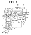
- FIGS. 1 to 10 are each a diagram showing an embodiment of the start control device for an internal combustion engine according to the invention.
- a cylinder block 1a of an engine 1 functioning as an internal combustion engine has four cylinders 2 that are arranged in the order of a first cylinder #1, second cylinder #2, third cylinder #3, and fourth cylinder #4. Note that FIG 1 shows the first cylinder #1 only.
- Each of the cylinders 2 accommodates therein a piston 3 so as to be movable in a reciprocal manner, and each piston 3 is coupled to a crankshaft 8 via a connecting rod 7. Reciprocating motion of the pistons 3 is converted to a rotational motion of the crankshaft 8 by the connecting rod 7. Note that the rotational position of the crankshaft 8 is expressed as a crank angle (° CA).
- a cylinder head 1b is secured to an upper part of the cylinder block 1a. The pistons 3 and the cylinder head 1b define combustion chambers 4 of the respective pistons 2.
- An intake camshaft 13 and exhaust camshaft 14 are supported rotatably to the cylinder head 1b, and an intake valve 11 and exhaust valve 12 are supported to the cylinder head 1b so as to be movable in a reciprocating manner with respect to each of the cylinders 2, and open and close the connection between each combustion chamber 4 and an intake and exhaust passages 9, 10, respectively.
- the intake camshaft 13 and the exhaust camshaft 14 are coupled to the crankshaft 8 by a timing belt 19.
- the intake camshaft 13 and the exhaust camshaft 14 rotate once while the crankshaft 8 rotates twice.
- VVT variable valve timing mechanism
- the VVT 18 is operated to change the rotation phase of the intake camshaft 13 corresponding to the crankshaft 8 in order to change the opening and closing timing of the intake valve 11.
- the VVT 18 is controlled by an electronic control unit (ECU) 100. Details of the ECU 100 constituted by a computer and the like will be described hereinafter.
- the fuel injection timing and the fuel injection amount are regulated by controlling the opening timing and the closing timing of the injector 5 by means of the ECU 100.
- the embodiment adopts a sequential injection system that sequentially injects fuel into the four cylinders 2. It goes without saying that other injection system may be adopted as well.
- each spark plug 6 is attached to the cylinder head 1b so as to correspond to each of the cylinders 2, and the spark plug 6 is electrically connected to an ignition coil 50. Based on high voltage supplied from the ignition coil 50, the spark plug 6 ignites a mixture of fuel and air supplied from the intake port 16 to each combustion chamber 4, and bums the mixture.
- the timing at which the high voltage is generated by the ignition coil 50, that is, the ignition timing of the spark plug 6, is regulated by controlling an igniter 49 by means of the ECU 100.
- the engine 1 is also provided with a starting device 20 serving as starting means.
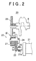
- the starting device 20 has a starter motor 21 serving as a starting motor, and a gear train 22 for transmitting the rotation of the starter motor 21 to the crankshaft 8 of the engine 1 as shown in FIG 2 .
- the gear train 22 has a starter gear 23 which is driven by an output shaft 21a of the starter motor 21, a driven gear 25 which is provided in engagement with the starter gear 23 on a supporting shaft 24 provided parallel to the crankshaft 8 and starter motor 21, an intermediate gear 27 which is provided coaxially with respect to the supporting shaft 24 via a one-way clutch 26 serving as the clutch, and a crank gear 28 which is provided in engagement with the intermediate gear 27 so as to be rotatable integrally with the crankshaft 8.
- the number-of-teeth ratio between the starter gear 23 and the driven gear 25 and the number-of-teeth ratio between the intermediate gear 27 and the crank gear 28 are each set such that the rotation of the starter motor 21 gradually slows down from the output shaft 21a side towards the crankshaft 8 side and the decelerated rotation is transmitted between the gears. In the gear train 22, therefore, the speed of the rotation is gradually reduced and the decelerated rotation is transmitted to the crankshaft 8.
- the driven gear 25 is capable of rotating integrally with the supporting shaft 24.
- the one-way clutch 26 is configured to allow the transmission of the rotation from the supporting shaft 24 to the intermediate gear 27 and inhibit the transmission of the rotation from the intermediate gear 27 to the supporting shaft 24. Specifically, the one-way clutch 26 allows the transmission of the rotation to the crankshaft 8 of the engine 1 and inhibits the transmission of the power of the crankshaft 8 to the starter motor 21.
- FIG 3 shows a specific configuration of the one-way clutch 26.
- the one-way clutch 26 is fitted tightly into an inner peripheral surface 27b of the intermediate gear 27.
- bearings 29, 30 are respectively fitted into inner peripheral surfaces 27a, 27c of the intermediate gear 27, and the one-way clutch 26 is sandwiched between the bearings 29, 30.
- the bearings 29, 30 and the one-way clutch 26 are fitted integrally into the supporting shaft 24 while being incorporated in the intermediate gear 27.
- Outer peripheral surfaces 24a, 24b, 24c of the supporting shaft 24 are configured such that their outer diameters decrease in the order of the outer peripheral surfaces 24a, 24b, 24c to fit the intermediate gear 27 from a shaft end part 24e side of the supporting shaft 24.
- a bearing 32 is press-fitted into the shaft end part 24e of the supporting shaft 24.
- the bearing 32 is retained by the intermediate gear 27 via a leaf spring 33.
- the supporting shaft 24 is supported rotatably by bearings 31, 32 fitted into shaft end parts 24d, 24e.
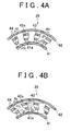
- the one-way clutch 26 has, as shown in FIG 4 , an inner ring 41 and an outer ring 42 surrounding the inner ring 41, a plurality of sprags 43 arranged in the gap between the inner ring 41 and the outer ring 42, and a pair of retainers 44 disposed coaxially with respect to the inner ring 41 and the outer ring 42 and supporting the positions of the sprags 43.
- Each of the sprag 43 functions as a transmission element for switching the direction of transmission of rotation based on the rotational speed of the engine 1, and is operated in the manner shown in FIGS. 4A and 4B .
- a normal direction rotation R1 is input to the inner ring 41, as shown in FIG 4A .
- the sprags 43 are brought into contact with both an outer peripheral surface 41a of the inner ring 41 and an outer peripheral surface 42a of the outer ring 42, and thus normal direction rotation R2 can be transmitted to the outer ring 42 by frictional force between the contacting surfaces.
- each of the cylinders #1 to #4 executes one engine cycle including an intake stroke, a compression stroke, an expansion stroke and an exhaust stroke during two revolutions of the crankshaft 8, as shown in FIG 5 . Therefore, the rotational position of the crankshaft 8 is expressed as one cycle with the rotation angle (i.e., 0° CA to 720° CA) corresponding to two revolutions of the crankshaft 8.
- the respective piston 3 within the first cylinder #1, the third cylinder #3, the fourth cylinder #4 and the second cylinder #2 in the engine 1 of the embodiment are disposed sequentially at the compression stroke top dead center (simply denoted as "TDC" in FIG 5 ) per 180° CA of the crankshaft 8.
- the pistons 3 within the respective cylinders 2 reciprocate in the order of the first cylinder #1, the third cylinder #3, the fourth cylinder #4, and the second cylinder #2 with a phase difference of 180° CA. Therefore, by defining the rotational position of the crankshaft 8 in the crank angle range of 0° CA to 720° CA, the stroke position of the piston 3 of the respective cylinder 2 can be identified, and thereby cylinder identification can be realized.
- each of the shaded areas corresponding mainly to the intake stroke of each cylinder #1 to #4 indicates an opening period of the intake valve 11, and each of the dotted areas above the shaded areas indicates a fuel injection period.
- the fuel-air mixture that is injected to the intake port 16 is introduced to the corresponding cylinder 2 as the intake valve 11 is opened.
- crankshaft 8 is provided with a crank rotor 45 as shown in FIG 6 .
- the crank rotor 45 rotates integrally with the crankshaft 8.
- a crank angle sensor 46 is provided in the vicinity of the crank rotor 45 and is attached to the cylinder block 1a of the engine 1 so as to face an outer peripheral surface of the crank rotor 45.
- the outer peripheral surface of the crank rotor 45 is provided with thirty-four projecting parts 45a arranged at equal intervals (i.e., per 10° CA in the embodiment). However, two adjacent projecting parts 45a at only one section of the outer peripheral surface of the crank rotor 45 are disposed at an interval of 30° CA.
- the shape of the crank rotor 45 is obtained by removing two continuous projections from thirty-six projections arranged at equal intervals.
- the section where the two continuous projections have been removed is termed "missing tooth part 45b" as a reference position for identifying the cylinder 2 on the crank rotor 45.
- crank angle sensor 46 generates one NE pulse signal (i.e., crank pulse), every time when each projecting part 45a passes the facing position of the crank angle sensor 46 as the crank rotor 45 rotates.
- a semiconductor-type sensor, a magnetic sensor such as a hall element and a magnetoresistance element, or an optical sensor can be used as the crank angle sensor 46.
- An electromagnetic pick up coil can also be used as the crank angle sensor 46.
- crank rotor 45 The material or the shape of the crank rotor 45 is determined in accordance with the utilized crank angle sensor 46 to induce corresponding pulses. That is, indicators such as concave parts or holes other than the projecting parts 45a may be provided on the crank rotor 45 in accordance with the type of the crank angle sensor 46.
- the NE pulse signal from the crank angle sensor 46 is input to the ECU 100.
- the ECU 100 then computes the crank angle at every rotation of 10° CA and the rotational speed of the engine 1 based on the NE pulse signal.
- the ECU 100 determines that the NE pulse signal corresponds to the missing tooth part 45b, and defines the missing tooth part 45b as the reference position of the crankshaft 8, so that the ECU 100 identifies, based on the reference position, the cylinder 2 on which the fuel injection control and ignition control is performed.
- crank angle sensor 46 and the ECU 100 in the embodiment may be respectively regarded as the “crank angle detection means” and the “reference position detection means” of the invention.
- the intake camshaft 13 is provided with a cam rotor 47.
- the cam rotor 47 rotates integrally with the intake camshaft 13.
- a cam position sensor 48 is provided in the vicinity of the intake camshaft 13 and is attached to the cylinder head 1b of the engine 1 so as to face an outer peripheral surface of the cam rotor 47.
- the outer peripheral surface of the cam rotor 47 is provided with a first projecting part 47a, a second projecting part 47b, and a third projecting part 47c.
- the second projecting part 47b and the third projecting part 47c serving as auxiliary indicators are disposed at an interval of 180°.
- the first projecting part 47a serving as an identification indicator that is used for identifying the cylinder is disposed at an interval of 90° with respect to both the second projecting part 47b and the third projecting part 47c. There is no projection in a position apart from the first projecting part 47a by 180°.
- the cam position sensor 48 generates one NE pulse signal (i.e., cam pulse), every time when the first projecting part 47a, the second projecting part 47b and the third projecting part 47c pass the facing position of the cam position sensor 48 as the cam rotor 47 rotates.
- NE pulse signal i.e., cam pulse
- a semiconductor-type sensor such as a magnetic sensor and an optical sensor, or an electromagnetic pick up coil can be used as the cam position sensor 48.
- the material or the shape of the cam rotor 47 is also determined in accordance with the utilized cam position sensor 48 to induce pulses. That is, indicators such as concave parts or holes other than the first projecting part 47a, the second projecting part 47b and the third projecting part 47c may be provided on the cam rotor 47 in accordance with the type of the cam position sensor 48.
- the ECU 100 is constituted by a computer having a central processing unit (CPU) 100a, a random access memory (RAM) 100b and a read only memory (ROM) 100c, and is configured to execute various processes required for controlling the operational state of the engine 1 in accordance with programs stored in the ROM 100c.
- CPU central processing unit
- RAM random access memory
- ROM read only memory
- the ECU 100 has an input circuit (not shown) to which signals are input from the crank angle sensor 46 and the cam position sensor 48, and an output circuit (not shown) from which drive signals are output to the injector 5 and the igniter 49.
- the igniter 49 functions to control the ignition timing of the spark plug 6.
- crank angle sensor 46 When the crank rotor 45 rotates along with the crankshaft 8, the crank angle sensor 46 generates a train of crank pulses as shown in FIG 5 , and outputs it to the ECU 100. As shown in FIG 6 , the crank angle sensor 46 generates one crank pulse at every rotation of 10° CA corresponding to the arrangement of the projecting parts 45a on the crank rotor 45.
- the missing tooth part 45b on the crank rotor 45 passes the crank angle sensor 46 once during one revolution of the crank rotor 45, the interval between the crank pulses corresponding to the projecting parts 45a before and behind the missing tooth part 45b becomes 30° CA, and thus a crank pulse that is clearly different from the 10° CA crank pulse is input to the ECU 100. Therefore, the ECU 100 can detect, based on the input 30° CA crank pulse, that the missing tooth part 45b on the crank rotor 45 has been passed.
- the ECU 100 can recognize, based on the input 30° CA crank pulse, that the crankshaft 8 is positioned at a specified rotation angle.
- the period until the crankshaft 8 rotates by a predetermined angle from the generation of the 30° CA crank pulse is set as an identifying period G (identifying angle range) for identifying the cylinder.
- the identifying period G is set at a period until the thirteenth crank pulse is generated from the generation of the 30° CA crank pulse (i.e., the first crank pulse). That is, the identifying period G is set at an angle range until the crankshaft 8 rotates by 120° CA from the detection of the missing tooth part 45b.
- the cam position sensor 48 when the intake camshaft 13 rotates along with the cam rotor 47, the cam position sensor 48 generates a first cam pulse CP1, a second cam pulse CP2 and a third cam pulse CP 3 corresponding to the first projecting part 47a, the second projecting part 47b and the third projecting part 47c respectively, and output these cam pulses to the ECU 100, as shown in FIG. 5 .
- the positional relationship between the crank angle sensor 46 and the crank rotor 45 and the positional relationship between the cam position sensor 48 and the cam rotor 47 are set such that the first cam pulse CP1 corresponding to the first projecting part 47a is generated during the identifying period G, as shown in FIG 5 .
- the crankshaft 8 rotates twice while the intake camshaft 13 rotates once, the identifying period G occurs twice.
- the first cam pulse CP1 serving as an identifying cam signal is generated in synchronism with one of the identifying periods G that occur twice during one revolution of the intake camshaft 13. Based on whether the first cam pulse CP1 is generated during the identifying period G, the rotational position of the crankshaft 8 during two revolutions thereof is specified so that the cylinder can be identified.
- the piston 3 of the first cylinder #1 when the first cam pulse CP1 is generated during the identifying period G as shown in FIG 5 , the piston 3 of the first cylinder #1 is disposed at the compression stroke top dead center, at a timing at which the tenth crank pulse is generated from the end of the identifying period G (i.e., the first crank pulse). That is, the piston 3 of the first cylinder #1 is disposed at the compression stroke top dead center after the crankshaft 8 rotates by 90° CA from the end of the identifying period G
- the piston 3 of the fourth cylinder #4 is disposed at the compression stroke top dead center, at a timing at which the tenth crank pulse is generated from the end of the identifying period G (i.e., the first crank pulse).
- crank counter value CCR indicating the crank angle is set at zero.
- the crank counter value CCR is incremented by "1" every time when the crankshaft 8 rotates by 30° CA, and is reset to zero once the crank counter value CCR reaches "23".
- the rotational position of the crankshaft 8 during its two revolutions is specified based on the crank counter value CCR so that the stroke position of the piston 3 in the respective cylinder 2 can be identified (i.e., the cylinder identification can be performed).
- the ignition control is performed at the timing at which the piston 3 reaches the compression stroke top dead center.
- the second cam pulse CP2 corresponding to the second projecting part 47b is generated during a period until the next missing tooth part 45b is detected from the end of the identifying period G during which the first cam pulse CP1 is generated.
- the second cam pulse CP 2 is generated after the intake camshaft 13 rotates by 90° (equivalent to 180° CA) from the generation of the first cam pulse CP1.
- the third cam pulse CP3 corresponding to the third projecting part 47c is generated during a period until the next missing tooth part 45b is detected from the end of the identifying period G during which the first cam pulse CP1 is not generated.
- the third cam pulse CP3 is generated after the intake camshaft 13 rotates by 180° (equivalent to 360° CA) from the generation of the second cam pulse CP2.
- each of the first cam pulse CP1, second cam pulse CP2 and third cam pulse CP3 is generated out of a fuel injection inhibition period for each of the cylinders #1 to #4, the fuel can be injected into any of the cylinders #1 to #4 irrespective of the timing at which the first cam pulse CP1, second cam pulse CP2 or third cam pulse CP3 is generated.
- output signals from a throttle sensor 51 for detecting the opening of the throttle valve 15 and from a shift position sensor 52 for detecting the position of the shift lever operated by a driver is input to the ECU 100.
- the ECU 100 determines that an idle reduction condition is satisfied and thereby stops the fuel injection and the ignition controls.
- the idle reduction condition may be satisfied, based on the output signal from the crank angle sensor 46, when the vehicle speed is zero and the duration in which the vehicle speed is zero lasts for a predetermined period.
- the ECU 100 is further configured to store the crank angle of the crankshaft 8 at every 10° CA upon stopping of the rotation of the crankshaft 8. For example, in the case where the crank angle detected by the crank angle sensor 46 is 50° CA, the ECU 100 stores "1" as the crank counter value.
- the ECU 100 in the embodiment may be regarded as "crank angle storing means" of the invention.
- the accelerator pedal when the accelerator pedal is operated during the idle reduction state, and thereby it is input to the ECU 100 that the opening of the throttle valve 15 indicates a value other than zero, the ECU 100 determines that the idle reduction condition is released, and the starting device 20 is activated.
- the ECU 100 is configured to compute a missing tooth detection target position as a target rotation angle of a predetermined crank angle from crank angles stored in the RAM 100b.
- the ECU 100 determines the presence of a failure in the starting device 20 based on determining whether the missing tooth part 45b is detected by the crank angle sensor 46 when the NE pulse signal detected by the crank angle sensor 46 is counted up by the crank angle corresponding to the missing tooth detection target position, that is, when the crankshaft 8 rotates by the target rotation angle from the stopped rotational position of the crankshaft 8.
- the ECU 100 After the engine 1 is started by the starting device 20, the ECU 100 identifies the cylinder to be ignited based on the result of determination on the presence of a failure in the starting device 20, and executes the fuel injection control and ignition control on the cylinder to be ignited.
- the ECU 100 in the embodiment determines that there is a high possibility of reverse rotation of the crankshaft 8 due to a failure in the starting device 20 in the case where the missing tooth part 45b is not detected when the counted-up value of the NE pulse signal detected by the crank angle sensor 46 becomes a pulse value corresponding to the missing tooth detection target position.
- crankshaft 8 rotates in the reverse direction immediately before it stops rotating for the idle reduction control, causing vibrations of the crankshaft 8.
- crank angle differs from the crank angle that is stored upon stoppage of the crankshaft 8. Therefore, if the cylinder is identified based on the stored crank angle to execute the fuel injection control and ignition control, erroneous ignition might occur.
- the ECU 100 in the embodiment determines that there is a high possibility of reverse rotation of the crankshaft 8 due to a failure in the starting device 20, performs control to stop executing the fuel injection control and ignition control on the cylinder supposed to be ignited (i.e., the cylinder that has been first determined to be ignited).
- the ECU 100 resets the missing tooth part 45b at the reference position when the crank angle sensor 46 has actually detected the missing tooth part 45b, and re-identifies the cylinder to be ignited, to execute the fuel injection control and ignition control on the cylinder.
- the ECU 100 alarms the failure of the starting device 20 to the driver in the case where the times of no detection of the missing tooth art 45b have been continued and have reached the predetermined number when the counted-up value of the NE pulse signal detected by the crank angle sensor 46 becomes the pulse value corresponding to the missing tooth detection target position.
- the ECU 100 alarms the failure of the starting device 20 to the driver by lighting up or blinking an economical run indicator 53. Alternatively, a sound or buzzer that appeals to the ear may be used for the alarm.
- the ECU 100 in the embodiment may be regarded as "target rotation angle computing means" and “failure determination means” of the invention.
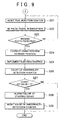
- FIGS. 8 and 9 show an abnormality detection program of the starting device 20 that is stored in the ROM 100c of the ECU 100 and executed by the CPU 100a.
- step S1 the CPU 100a of the ECU 100 determines whether the idle reduction condition is satisfied (step S1).
- step S1 in the case where it is determined based on the output signals from the throttle sensor 51 and shift position sensor 52 that the throttle opening is zero with the shift lever being in the "neutral position” or "parking position," the CPU 100a determines that the idle reduction condition is satisfied, and stops the fuel injection control and ignition control.
- the CPU 100a determines whether the engine 1 is stopped (step S2). Then, when it is determined that the engine is stopped, the ECU 100 stores a stopped-crank position (step S3).
- the crank angle of the crankshaft 8 is stored at every rotation of 10° CA when the crankshaft 8 stops rotating. As shown in FIG 5 , when the crank angle between two projecting parts 45a detected by the crank angle sensor 46 is 50° CA, the number "1" is stored as the crank counter value.
- the CPU 100a determines whether the starting device 20 is switched "on", that is, whether the starter motor 21 is activated (step S4). Specifically, when the throttle sensor 51 outputs a signal indicating that the throttle opening is not zero at least due to a depression of the accelerator pedal, it is determined that the idle reduction condition is released, and thus the starting device 20 is switched "on.”
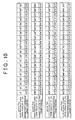
- the CPU 100a computes the missing tooth detection target position by using the map shown in FIG 10 (step S5).
- the map for computing the missing tooth detection target position is stored in the ROM 100c of the ECU 100.
- FIG 10 shows the stop position of the crankshaft 8 and the missing tooth detection target position that defines a position until the missing tooth part 45b is detected from the stop position of the crankshaft 8. That is, FIG 10 shows the relationship of the target rotation angle of the crank angle.
- the missing tooth detection target position is set at the position of 210°. For example, when the stopped-crank position is at 10° CA, it is predicted that the missing tooth part 45b is detected when the crank rotor 45 rotates by 210° CA from the stopped-crank position of 10° CA.
- the missing tooth detection target position is set at the position of 570°.
- the stopped-crank position is at 50° CA
- the missing tooth part 45b is detected twice when the crank rotor 45 rotates by 570° CA from the stopped-crank position.
- the pulse signal by which the missing tooth part 45b is first detected is obtained at 20° CA
- the pulse signal is obtained at 10° CA. Because such extremely unstable signals are obtained immediately after the start of the starting device, the ECU 100 ignores the pulse signal corresponding to 30° CA that is first input from the crank angle sensor 46.
- the gap between the missing tooth detection target position and the stop position of the crankshaft 8 is made wider because the missing tooth part 45b can be detected accurately between the stop position of the crankshaft 8 and the missing tooth detection target position if the crankshaft 8 does not rotate in the reverse direction.
- NE pulse signal interruption is performed based on the output signal from the crank angle sensor 46 (step S6), and then the NE pulse signal is counted up from the stopped-crank position stored in the RAM 100b (step S7).
- step S8 the cylinder to be ignited is identified based on the stop position of the crankshaft 8 that is stored in the RAM 100b, to execute fuel injection (step S8).
- the crank counter value stored in the RAM 100b is "1," the fuel is injected into the fourth cylinder #4.
- step S9 it is determined whether the NE pulse signal that is input after the crankshaft 8 stops rotating becomes the counted-up value corresponding to the missing tooth detection target position.
- the NE pulse signal obtained at the stop position of the crankshaft 8 is 50° CA, it is determined whether the missing tooth detection target position is at 210°.
- the CPU 100a When it is determined that the counted-up value of the NE pulse signal does not reach the missing tooth detection target position, the CPU 100a returns to step S5. Also, when it is determined that the crank angle is in the position where the missing tooth part 45b is to be detected, the CPU 100a determines whether a 30° CA signal is detected or, in other words, whether the detection of the missing tooth is already done (step S10).
- step S10 if it is determined that the missing tooth part 45b has been detected when the counted-up value of the NE pulse signal detected by the crank angle sensor 46 from the stop position of the crankshaft 8 has reached the missing tooth detection target position, start control for economical running is executed (step S11), and the processing is ended.
- step S10 determines that the missing tooth part 45b has been already detected once the NE pulse signal is counted up by 210° CA from the stop position. Consequently, the starting device 20 is determined to be normal and the fourth cylinder #4 is ignited in step S11. The fuel injection following the fourth cylinder #4 is executed on the second cylinder #2, the first cylinder #1 and the third cylinder #3 in sequence.
- step S10 the CPU 100a determines that there is a possibility of a failure in the starting device 20 due to the fact that the missing tooth part 45b has not been detected, although the counted-up value of the NE pulse signal detected by the crank angle sensor 46 from the stop position of the crankshaft 8 has reached the missing tooth detection target position.
- the CPU 100a then resets the fuel injection control and ignition control to be performed on the cylinder that has been supposed to be ignited, as shown in FIG 9 (step S21).
- the one-way clutch 26 provided in the starting device 20, which prevents the reverse rotation of the crankshaft 8, allows the transmission of the rotation from the supporting shaft 24 to the intermediate gear 27 while inhibiting the transmission of the rotation from the intermediate gear 27 to the supporting shaft 24.
- step S21 the fuel injection control and ignition control are reset to prevent erroneous ignition of the cylinder other than the cylinder to be correctly ignited.
- NE pulse signal interruption is performed based on the output signal from the crank angle sensor 46 (step S22), to determine whether the 30° CA signal is detected or, in other words, whether the missing tooth is detected (step S23).
- step S23 When it is determined in step S23 that the missing tooth is detected, the CPU 100a corrects the crank position based on the missing tooth part 45b detected by the crank angle sensor 46 (step S24), and determines, based on the corrected crank position, the cylinder to be ignited. Then, the CPU 100a executes the fuel injection control and ignition control (step S25).
- the CPU 100a counts up the abnormality detection counter provided in the RAM 100b (step S26) and determines whether the counted-up value of the abnormality detection counter is equal to or above a predetermined value, i.e., "5" (step S27).
- the CPU 100a ends the processing.
- the CPU 100a determines that a failure occurs in the starting device 20 because the missing tooth part 45b has not been detected five times in a row, although the counted-up value of the NE pulse signal detected by the crank angle sensor 46 became the pulse value corresponding to the missing tooth detection target position.
- the CPU 100a then alarms the failure of the starting device 20 to the driver by lighting up or blinking the economical run indicator 53 (step S28). Then, the CPU 100a resets the value of the abnormality detection counter (step S29) and ends the processing.
- the target rotation angle between the crank angle stored upon stoppage of the crankshaft 8 and the crank angle at the reference position is computed. Then, in the case where the crankshaft 8 rotates by the target rotation angle from the rotation stop position of the crankshaft 8 after the engine 1 is started by the starting device 20, it is determined whether the crankshaft 8 is driven to rotate in the reverse direction due to abnormalities caused in the one-way clutch 26 and the like based on whether the missing tooth part 45b has been detected. Accordingly, the presence of a failure in the starting device 20 can be determined accurately.
- the missing tooth part 45b has been detected when the crankshaft 8 rotates by the target rotation angle from the rotation stop position of the crankshaft 8 after the engine 1 is started by the starting device 20, it is determined that the starting device 20 is normal, and then the cylinder to be ignited is identified to execute the fuel injection control and ignition control on that cylinder. Consequently, startability of the engine 1 can be improved.
- the CPU 100a stops fuel injection control and ignition control on the cylinder that is supposed to be ignited because there is a high possibility of the reverse rotation of the crankshaft 8 due to a failure in the starting device 20. Therefore, an erroneous ignition can be prevented from occurring after the activation of the starting device 20, and thereby the engine 1 can be prevented from being imposed with an overload.
- the CPU 100a in the case where the missing tooth part 45b has not been detected when the crankshaft 8 rotates by the target rotation angle from the rotation stop position of the crankshaft 8 after the engine 1 is started by the starting device 20, the CPU 100a re-identifies the cylinder to be ignited based on the missing tooth part 45b detected by the crank angle sensor 46, and perform the fuel injection control and ignition control on that cylinder because there is a high possibility of the reverse rotation of the crankshaft 8 due to a failure in the starting device 20. Consequently, even if the starting device 20 has a failure, the cylinder to be ignited can be identified accurately, and thereby the occurrence of erroneous ignition can be prevented securely.
- the failure of the starting device 20 is alarmed by means of the economical run indicator 53.
- the crankshaft 8 rotates by the target rotation angle from the rotation stop position of the crankshaft 8 after the engine 1 is started by the starting device 20
- the starting device 20 has a secure failure, which is alarmed by means of the economical run indicator 53. Consequently, the driver can be notified of the failure of the starting device 20 so that a prompt response of the driver can be promoted.
- the starting device 20 can be used continuously.
- the one-way clutch according to the embodiment utilizes the sprags
- a roller assembly that has rollers functioning as meshing members and springs for urging the rollers may be alternatively utilized.
- an outer race type cam in which the outer race is provided with a flat or curved cam surface may be utilized.
- an inner race type cam in which the inner race is provided with a cam surface may be utilized.
- the start control device for an internal combustion engine has the advantage of accurately determining the presence of a failure in the starting means, and may be useful as a starting control device and the like for an internal combustion engine that determines the presence of a failure in the starting means for starting the internal combustion engine.
Landscapes
- Engineering & Computer Science (AREA)
- Chemical & Material Sciences (AREA)
- Combustion & Propulsion (AREA)
- Mechanical Engineering (AREA)
- General Engineering & Computer Science (AREA)
- Combined Controls Of Internal Combustion Engines (AREA)
- Electrical Control Of Air Or Fuel Supplied To Internal-Combustion Engine (AREA)
- Ignition Installations For Internal Combustion Engines (AREA)
- Output Control And Ontrol Of Special Type Engine (AREA)
Abstract
Description
- The invention relates to a start control device for an internal combustion engine, which determines the presence of a failure in starting means for starting the internal combustion engine.
- From the perspective of energy conservation and reduction of carbon dioxide emissions, installation of an idle reduction function for automatically stopping an internal combustion engine upon stoppage of a vehicle is encouraged.
- Also, as starting means that is suitable for a vehicle installed with the idle reduction function, there is known a starting device that is provided with a one-way clutch that brings a pinion gear of a starter motor into constant engagement with a ring gear of a crankshaft to allow transmission of rotation from the starter motor to the crankshaft of an internal combustion engine and to inhibit transmission of power from the crankshaft to the starter motor (see Japanese Patent Application Publication No.
2005-9430 JP-A-2005-9430 - Also, there is a device which promptly identifies a cylinder for performing fuel injection and ignition upon starting of an internal combustion engine to thereby perform control of fuel injection and ignition on the cylinder, in order to improve startability of the internal combustion engine in a vehicle having the idle reduction function (see Japanese Patent Application Publication No.
11-13528 JP-A-11-13528 - The device disclosed in
JP-A-11-13528 - The NE sensor outputs a pulse signal corresponding to each of the first teeth at every crank angle of 10° and a reference position signal corresponding to the first missing tooth part when the first rotating body rotates as the crankshaft rotates, while the G sensor outputs a pulse signal corresponding to the second tooth at, for example, every crank angle of 360°.
- The crank angle and the TDC of each cylinder are obtained based on the pulse signals output from the NE sensor and G sensor. For example, in the case where the pulse signal corresponding to the first missing tooth part is output from the NE sensor, a TDC of the
first cylinder # 1 or thefourth cylinder # 4 is determined when a pulse signal corresponding to a first tooth subsequent to the first missing tooth part is output, and a TDC of thethird cylinder # 3 or thesecond cylinder # 2 is determined after a crank angle of 180° (18 pulses) from the TDC. - In the above method, however, it is difficult to identify which of the
first cylinder # 1 and thefourth cylinder # 4 is the relevant cylinder. Therefore, when the G sensor outputs a pulse signal corresponding to the teeth of the second rotating body, it is determined that the relevant cylinder corresponds to thefirst cylinder # 1. - The stop positions of the crankshaft and the camshaft can be found based on the pulse signals output from the NE sensor and G sensor before the starting means is activated (upon idle reduction). Therefore, the cylinder that performs fuel injection and ignition is identified based on the stop positions of the crankshaft and the camshaft, and the start of the internal combustion engine can be completed by promptly performing fuel injection and ignition in the corresponding cylinder immediately after the crankshaft starts rotating upon activation of the starting means.
- On the other hand, because the above-described starting means with the one-way clutch can allow transmission of rotation from the starter motor to the crankshaft of the internal combustion engine and inhibit transmission of power from the crankshaft to the starter motor, vibrations of the crankshaft caused immediately before the internal combustion engine is stopped. Thus, the stop positions of the crankshaft and the camshaft can be found more easily based on the pulse signals output from the NE sensor and G sensor.
- Specifically, immediately before the internal combustion engine is stopped, the piston during its compression stroke is pressed back in the vicinity of the top dead center by an increased air pressure of the piston without being unable to exceed the top dead center, whereby the rotation of the crankshaft is reversed.
- However, because the starting means with the one-way clutch can inhibit transmission of power from the crankshaft to the starter motor, the starting means and the crankshaft are locked by the one-way clutch so that the crankshaft is prevented from rotating in the reverse direction.
- In the starting means with the one-way clutch, in the case of a situation where the crankshaft cannot be prevented from rotating in the reverse direction due to abnormalities caused in the one-way clutch, a signal that is output from the NE sensor immediately before the internal combustion engine is stopped is obtained as an output signal containing a normal rotation signal and a reverse rotation signal. For the reason, the stop position of the crankshaft might not be detected accurately.
- Therefore, a different cylinder other than the cylinder to be ignited upon activation of the starting means may be ignited, which causes an overload on the internal combustion engine. Hence, it is desired to accurately determine a failure in the starting means.
- The invention provides a start control device for an internal combustion engine, which accurately determines the presence of a failure in starting means.
- A start control device for an internal combustion engine according to the invention, which includes a starting motor and a one-way clutch that transmits power of the starting motor to a crankshaft of an internal combustion engine and inhibits transmission of power from the crankshaft to the starting motor. Furthermore, the start control device includes: starting means for starting the internal combustion engine; crank angle detection means for detecting a crank angle of the crankshaft; reference position detection means for detecting a reference position that is set at the crank angle; crank angle storing means for storing a crank angle obtained when the crankshaft stops rotating; target rotation angle computing means for computing a target rotation angle of a crank angle that is defined based on the stored crank angle; and failure determination means for determining the presence of a failure in the starting means based on determining whether the reference position has been detected when the crankshaft has rotated by the target rotation angle after the internal combustion engine had been started by the starting means.
- According to the configuration, a target rotation angle of a crank angle between the crank angle stored upon stoppage of the crankshaft and the reference position can be computed. Also, when the crankshaft rotates by the target rotation angle after the internal combustion engine is started by the starting means, it is determined whether the reference position is detected, and thereby it is possible to determine whether the crankshaft is driven to rotate in a reverse direction due to any abnormalities caused in the one-way clutch and the like. Accordingly, the presence of a failure in the starting means can be determined accurately.
- The failure determination means may determine the presence of a failure in the starting means based on determining whether the crankshaft is driven to rotate in the reverse direction.
- The failure determination means may determine the starting means has a failure if the reference position is not detected when the crankshaft rotates by the target rotation angle from the rotation stop position of the crankshaft.
- The failure determination means determines the crankshaft is driven to rotate in the reverse direction due to an abnormality in one-way clutch when it is determined that the starting means has a failure.
- The start control device may further include internal combustion engine control means for stopping fuel injection control and ignition control when a stopping condition of the internal combustion engine is satisfied, and executing the fuel injection control and ignition control on a cylinder when the internal combustion engine is started by the starting means. In the case where the failure determination means determines that the reference position is detected by the reference position detection means when the crankshaft rotates by the target rotation angle since the crankshaft stops rotating, the internal combustion engine control means identifies one cylinder to be ignited among a plurality of cylinders and executes the fuel injection control and ignition control on the cylinder to be ignited; and in the case where the failure determination means determines that the reference position is not detected by the reference position detection means when the crankshaft rotates by the target rotation angle since the crankshaft stops rotating, the internal combustion engine control means stops performing the fuel injection control and ignition control on a cylinder that is first determined to be ignited.
- According to the configuration, in the case where the reference position is detected when the crankshaft rotates by the target rotation angle since the crankshaft stops rotating, it is determined that the starting means is normal, and a cylinder to be ignited can be identified promptly to execute fuel injection control and ignition control on the cylinder to be ignited. Consequently, startability of the internal combustion engine can be improved. Moreover, in the case where the reference position is not detected when the crankshaft rotates by the target rotation angle since the crankshaft stops rotating, there is a high possibility of a failure in the starting means and of reverse rotation of the crankshaft. For the reason, the fuel injection control and ignition control are not performed on the cylinder that is supposed to be ignited, whereby erroneous ignition can be prevented from occurring after starting the internal combustion engine and the internal combustion engine can be prevented from being imposed with an overload.
- Also, in the case where the failure determination means determines that the reference position is not detected by the reference position detection means when the crankshaft rotates by the target rotation angle since the crankshaft stops rotating, the internal combustion engine control means may, again, identify the cylinder to be ignited based on the reference position detected by the reference position detection means, and execute the fuel injection control and ignition control on the cylinder.
- According to the configuration, in the case where the reference position is not detected when the crankshaft rotates by the target rotation angle since the crankshaft stops rotating after the internal combustion engine is started by the starting means, there is a high possibility of a failure in the starting means and of reverse rotation of the crankshaft. For the reason, the cylinder to be ignited is identified again based on the reference position that is set at the actual detected crank angle, to perform the fuel injection control and ignition control, so that the cylinder to be ignited can be identified accurately and the cylinder can be ignited. Consequently, even when the starting means is damaged, the cylinder to be ignited can be identified accurately and the occurrence of erroneous ignition can be prevented securely.
- Furthermore, in the case where the failure determination means determines that the reference position is not detected by the reference position detection means predetermined times in a row when the crankshaft rotates by the target rotation angle since the crankshaft stops rotating, the failure determination means may alarm a failure of the starting means.
- According to the configuration, when the situation where the reference position is not detected by the reference position detection means occurs repeatedly after the internal combustion engine is started by the starting means although the crankshaft rotates by the target rotation angle since the crankshaft stops rotating, it is determined that the starting means is truly damaged and a alarm to that effect is issued, whereby an operator can be notified of the failure of the starting means so that a prompt response can be promoted regarding such occurrence.
- Furthermore, when the situation where the reference position is not detected by the reference position detection means occurs continuously below a predetermined number of times after the internal combustion engine is started by the starting means although the crankshaft rotates by the target rotation angle since the crankshaft stops rotating, it is determined that a detection signal of the crank angle is influenced by noise or the like and thus a failure is not alarmed. Therefore, the starting means can be used continuously.
- The start control device may further include throttle opening detection means for detecting an opening of a throttle valve; and shift position detection means for detecting a shift position of an automatic transmission. The stopping condition of the internal combustion engine may be satisfied when the opening of the throttle valve is zero with one of neutral position and parking position.
- The start control device may further include vehicle speed detection means for detecting a vehicle speed, and the stopping condition of the internal combustion engine may be satisfied when a vehicle speed is zero with the duration in which the vehicle speed is zero lasting for a predetermined period.
- The foregoing and further objects, features and advantages of the invention will become apparent from the following description of preferred embodiments with reference to the accompanying drawings, wherein like numerals are used to represent like element and wherein:
-
FIG 1 is a cross-sectional diagram of an embodiment of a start control device for an internal combustion engine according to the invention, wherein a substantial part of an internal combustion engine is shown; -
FIG 2 is a partial cross-sectional diagram of an embodiment of the start control device for an internal combustion engine according to the invention, wherein a substantial part of a starting device provided in an engine is shown; -
FIG 3 is an enlarged diagram of an embodiment of the start control device for an internal combustion engine according to the invention that is shown at III ofFIG 2 ; -
FIG 4 is a diagram of an embodiment of the start control device for an internal combustion engine according to the invention, wherein how a one-way clutch is activated is shown; -
FIG 5 is a timing chart of an embodiment of the start control device for an internal combustion engine according to the invention, wherein an operation of the internal combustion engine is shown; -
FIG 6 is a diagram of an embodiment of the start control device for an internal combustion engine according to the invention, wherein a crank rotor is shown; -
FIG 7 is a diagram of an embodiment of the start control device for an internal combustion engine according to the invention, wherein a cam rotor is shown; -
FIG 8 is a diagram of an embodiment of the start control device for an internal combustion engine according to the invention, wherein a starting device abnormality detection program is shown; -
FIG 9 shows the starting device abnormality detection program subsequent to that ofFIG 8 ; and -
FIG 10 is a diagram of an embodiment of the start control device for an internal combustion engine according to the invention, wherein a relationship between a missing tooth detection target position and a stop position of a crankshaft is shown. - Embodiments of a start control device for an internal combustion engine according to the invention are described hereinafter with reference to the drawings.
FIGS. 1 to 10 are each a diagram showing an embodiment of the start control device for an internal combustion engine according to the invention. - In
FIG 1 , a cylinder block 1a of anengine 1 functioning as an internal combustion engine has fourcylinders 2 that are arranged in the order of afirst cylinder # 1,second cylinder # 2,third cylinder # 3, andfourth cylinder # 4. Note thatFIG 1 shows thefirst cylinder # 1 only. - Each of the
cylinders 2 accommodates therein apiston 3 so as to be movable in a reciprocal manner, and eachpiston 3 is coupled to acrankshaft 8 via a connectingrod 7. Reciprocating motion of thepistons 3 is converted to a rotational motion of thecrankshaft 8 by the connectingrod 7. Note that the rotational position of thecrankshaft 8 is expressed as a crank angle (° CA). A cylinder head 1b is secured to an upper part of the cylinder block 1a. Thepistons 3 and the cylinder head 1b definecombustion chambers 4 of therespective pistons 2. - An
intake camshaft 13 andexhaust camshaft 14 are supported rotatably to the cylinder head 1b, and an intake valve 11 andexhaust valve 12 are supported to the cylinder head 1b so as to be movable in a reciprocating manner with respect to each of thecylinders 2, and open and close the connection between eachcombustion chamber 4 and an intake andexhaust passages - Also, a
throttle valve 15, which is provided within theintake passage 9, changes its opening depending on the pedaling amount of an accelerator pedal, which is not shown. - The
intake camshaft 13 and theexhaust camshaft 14 are coupled to thecrankshaft 8 by atiming belt 19. Theintake camshaft 13 and theexhaust camshaft 14 rotate once while thecrankshaft 8 rotates twice. - When the
intake camshaft 13 and theexhaust camshaft 14 rotate, the intake valve 11 and theexhaust valve 12 are drive by the respectivelyintake camshaft 13 andexhaust camshaft 14. As the intake valve 11 and theexhaust valve 12 are driven, eachintake port 16 and exhaust port 17 are opened or closed at a predetermined timing. - A variable valve timing mechanism (hereinafter simply referred to as "VVT") 18 for changing opening and closing timings of the intake valve 11 is disposed between the
intake camshaft 13 and thetiming belt 19. TheVVT 18 is operated to change the rotation phase of theintake camshaft 13 corresponding to thecrankshaft 8 in order to change the opening and closing timing of the intake valve 11. TheVVT 18 is controlled by an electronic control unit (ECU) 100. Details of theECU 100 constituted by a computer and the like will be described hereinafter. - An
injector 5, configured by an electromagnetic valve functions as fuel injection means, is provided in theintake port 16 so as to correspond to each of thecylinders 2. Eachinjector 5 injects fuel into thecorresponding intake port 16. - The fuel injection timing and the fuel injection amount are regulated by controlling the opening timing and the closing timing of the
injector 5 by means of theECU 100. Note that the embodiment adopts a sequential injection system that sequentially injects fuel into the fourcylinders 2. It goes without saying that other injection system may be adopted as well. - Moreover, each
spark plug 6 is attached to the cylinder head 1b so as to correspond to each of thecylinders 2, and thespark plug 6 is electrically connected to anignition coil 50. Based on high voltage supplied from theignition coil 50, thespark plug 6 ignites a mixture of fuel and air supplied from theintake port 16 to eachcombustion chamber 4, and bums the mixture. - The timing at which the high voltage is generated by the
ignition coil 50, that is, the ignition timing of thespark plug 6, is regulated by controlling anigniter 49 by means of theECU 100. - The
engine 1 is also provided with a startingdevice 20 serving as starting means. The startingdevice 20 has astarter motor 21 serving as a starting motor, and agear train 22 for transmitting the rotation of thestarter motor 21 to thecrankshaft 8 of theengine 1 as shown inFIG 2 . - The
gear train 22 has astarter gear 23 which is driven by anoutput shaft 21a of thestarter motor 21, a drivengear 25 which is provided in engagement with thestarter gear 23 on a supportingshaft 24 provided parallel to thecrankshaft 8 andstarter motor 21, anintermediate gear 27 which is provided coaxially with respect to the supportingshaft 24 via a one-way clutch 26 serving as the clutch, and acrank gear 28 which is provided in engagement with theintermediate gear 27 so as to be rotatable integrally with thecrankshaft 8. - The number-of-teeth ratio between the
starter gear 23 and the drivengear 25 and the number-of-teeth ratio between theintermediate gear 27 and thecrank gear 28 are each set such that the rotation of thestarter motor 21 gradually slows down from theoutput shaft 21a side towards thecrankshaft 8 side and the decelerated rotation is transmitted between the gears. In thegear train 22, therefore, the speed of the rotation is gradually reduced and the decelerated rotation is transmitted to thecrankshaft 8. Note that the drivengear 25 is capable of rotating integrally with the supportingshaft 24. - The one-way clutch 26 is configured to allow the transmission of the rotation from the supporting
shaft 24 to theintermediate gear 27 and inhibit the transmission of the rotation from theintermediate gear 27 to the supportingshaft 24. Specifically, the one-way clutch 26 allows the transmission of the rotation to thecrankshaft 8 of theengine 1 and inhibits the transmission of the power of thecrankshaft 8 to thestarter motor 21. -
FIG 3 shows a specific configuration of the one-way clutch 26. InFIG 3 , the one-way clutch 26 is fitted tightly into an innerperipheral surface 27b of theintermediate gear 27. On the other hand,bearings peripheral surfaces 27a, 27c of theintermediate gear 27, and the one-way clutch 26 is sandwiched between thebearings - The
bearings shaft 24 while being incorporated in theintermediate gear 27. Outerperipheral surfaces shaft 24 are configured such that their outer diameters decrease in the order of the outerperipheral surfaces intermediate gear 27 from ashaft end part 24e side of the supportingshaft 24. - Also, a
bearing 32 is press-fitted into theshaft end part 24e of the supportingshaft 24. Thebearing 32 is retained by theintermediate gear 27 via aleaf spring 33. The supportingshaft 24 is supported rotatably bybearings shaft end parts - On the other hand, the one-way clutch 26 has, as shown in
FIG 4 , aninner ring 41 and anouter ring 42 surrounding theinner ring 41, a plurality ofsprags 43 arranged in the gap between theinner ring 41 and theouter ring 42, and a pair ofretainers 44 disposed coaxially with respect to theinner ring 41 and theouter ring 42 and supporting the positions of thesprags 43. - Each of the
sprag 43 functions as a transmission element for switching the direction of transmission of rotation based on the rotational speed of theengine 1, and is operated in the manner shown inFIGS. 4A and 4B . Specifically, when theengine 1 is started, a normal direction rotation R1 is input to theinner ring 41, as shown inFIG 4A . At the moment, thesprags 43 are brought into contact with both an outerperipheral surface 41a of theinner ring 41 and an outerperipheral surface 42a of theouter ring 42, and thus normal direction rotation R2 can be transmitted to theouter ring 42 by frictional force between the contacting surfaces. - When the
engine 1 is operated, on the other hand, the rotation of thecrankshaft 8 is transmitted to theouter ring 42 and normal direction rotation R3 is input, as shown inFIG 4B . At the moment, thesprags 43 are rotated and tilted in a direction of the arrow r1 by a centrifugal force. In eachsprag 43, because one diagonal length L1 thereof is shorter than the other diagonal length L2, the tiltedsprags 43 can no longer come into contact with the outerperipheral surface 41a of theinner ring 41. - Because the
outer ring 42 rotates idly around theinner ring 41 along with thesprags 43, transmission of the normal direction rotation R3 of theouter ring 42 is inhibited. As the centrifugal force acting on thesprags 43 becomes small immediately before theengine 1 is stopped, thesprags 43 return to the positions shown inFIG 4A . As a result, theintermediate gear 27 is locked by the one-way clutch 26 when the vehicle stops. Consequently, thestarter motor 21 and thecrankshaft 8 are also locked by the one-way clutch 26 so that thecrankshaft 8 is prevented from rotating in the reverse direction. - On the other hand, each of the
cylinders # 1 to #4 executes one engine cycle including an intake stroke, a compression stroke, an expansion stroke and an exhaust stroke during two revolutions of thecrankshaft 8, as shown inFIG 5 . Therefore, the rotational position of thecrankshaft 8 is expressed as one cycle with the rotation angle (i.e., 0° CA to 720° CA) corresponding to two revolutions of thecrankshaft 8. - Moreover, as shown in
FIG 5 , therespective piston 3 within thefirst cylinder # 1, thethird cylinder # 3, thefourth cylinder # 4 and thesecond cylinder # 2 in theengine 1 of the embodiment are disposed sequentially at the compression stroke top dead center (simply denoted as "TDC" inFIG 5 ) per 180° CA of thecrankshaft 8. - In other words, the
pistons 3 within therespective cylinders 2 reciprocate in the order of thefirst cylinder # 1, thethird cylinder # 3, thefourth cylinder # 4, and thesecond cylinder # 2 with a phase difference of 180° CA. Therefore, by defining the rotational position of thecrankshaft 8 in the crank angle range of 0° CA to 720° CA, the stroke position of thepiston 3 of therespective cylinder 2 can be identified, and thereby cylinder identification can be realized. - Note in
FIG 5 that each of the shaded areas corresponding mainly to the intake stroke of eachcylinder # 1 to #4 indicates an opening period of the intake valve 11, and each of the dotted areas above the shaded areas indicates a fuel injection period. The fuel-air mixture that is injected to theintake port 16 is introduced to thecorresponding cylinder 2 as the intake valve 11 is opened. - Furthermore, the
crankshaft 8 is provided with acrank rotor 45 as shown inFIG 6 . Thecrank rotor 45 rotates integrally with thecrankshaft 8. Acrank angle sensor 46 is provided in the vicinity of thecrank rotor 45 and is attached to the cylinder block 1a of theengine 1 so as to face an outer peripheral surface of thecrank rotor 45. - The outer peripheral surface of the
crank rotor 45 is provided with thirty-four projectingparts 45a arranged at equal intervals (i.e., per 10° CA in the embodiment). However, two adjacent projectingparts 45a at only one section of the outer peripheral surface of thecrank rotor 45 are disposed at an interval of 30° CA. - Therefore, the shape of the
crank rotor 45 is obtained by removing two continuous projections from thirty-six projections arranged at equal intervals. The section where the two continuous projections have been removed is termed "missing tooth part 45b" as a reference position for identifying thecylinder 2 on thecrank rotor 45. - The
crank angle sensor 46 generates one NE pulse signal (i.e., crank pulse), every time when each projectingpart 45a passes the facing position of thecrank angle sensor 46 as thecrank rotor 45 rotates. - A semiconductor-type sensor, a magnetic sensor such as a hall element and a magnetoresistance element, or an optical sensor can be used as the
crank angle sensor 46. An electromagnetic pick up coil can also be used as thecrank angle sensor 46. - The material or the shape of the
crank rotor 45 is determined in accordance with the utilizedcrank angle sensor 46 to induce corresponding pulses. That is, indicators such as concave parts or holes other than the projectingparts 45a may be provided on thecrank rotor 45 in accordance with the type of thecrank angle sensor 46. - In addition, the NE pulse signal from the
crank angle sensor 46 is input to theECU 100. TheECU 100 then computes the crank angle at every rotation of 10° CA and the rotational speed of theengine 1 based on the NE pulse signal. - When an NE pulse signal corresponding to a long interval between adjacent projecting
parts 45a is input to theECU 100, theECU 100 determines that the NE pulse signal corresponds to the missing tooth part 45b, and defines the missing tooth part 45b as the reference position of thecrankshaft 8, so that theECU 100 identifies, based on the reference position, thecylinder 2 on which the fuel injection control and ignition control is performed. - The
crank angle sensor 46 and theECU 100 in the embodiment may be respectively regarded as the "crank angle detection means" and the "reference position detection means" of the invention. - As shown in
FIG 7 , theintake camshaft 13 is provided with acam rotor 47. Thecam rotor 47 rotates integrally with theintake camshaft 13. Acam position sensor 48 is provided in the vicinity of theintake camshaft 13 and is attached to the cylinder head 1b of theengine 1 so as to face an outer peripheral surface of thecam rotor 47. - The outer peripheral surface of the
cam rotor 47 is provided with a first projectingpart 47a, a second projectingpart 47b, and a third projectingpart 47c. Among them, the second projectingpart 47b and the third projectingpart 47c serving as auxiliary indicators are disposed at an interval of 180°. - On the other hand, the first projecting
part 47a serving as an identification indicator that is used for identifying the cylinder, is disposed at an interval of 90° with respect to both the second projectingpart 47b and the third projectingpart 47c. There is no projection in a position apart from the first projectingpart 47a by 180°. - The
cam position sensor 48 generates one NE pulse signal (i.e., cam pulse), every time when the first projectingpart 47a, the second projectingpart 47b and the third projectingpart 47c pass the facing position of thecam position sensor 48 as thecam rotor 47 rotates. - As with the
crank angle sensor 46, a semiconductor-type sensor such as a magnetic sensor and an optical sensor, or an electromagnetic pick up coil can be used as thecam position sensor 48. The material or the shape of thecam rotor 47 is also determined in accordance with the utilizedcam position sensor 48 to induce pulses. That is, indicators such as concave parts or holes other than the first projectingpart 47a, the second projectingpart 47b and the third projectingpart 47c may be provided on thecam rotor 47 in accordance with the type of thecam position sensor 48. - The
ECU 100 is constituted by a computer having a central processing unit (CPU) 100a, a random access memory (RAM) 100b and a read only memory (ROM) 100c, and is configured to execute various processes required for controlling the operational state of theengine 1 in accordance with programs stored in theROM 100c. - Also, the
ECU 100 has an input circuit (not shown) to which signals are input from thecrank angle sensor 46 and thecam position sensor 48, and an output circuit (not shown) from which drive signals are output to theinjector 5 and theigniter 49. Theigniter 49 functions to control the ignition timing of thespark plug 6. - When the
crank rotor 45 rotates along with thecrankshaft 8, thecrank angle sensor 46 generates a train of crank pulses as shown inFIG 5 , and outputs it to theECU 100. As shown inFIG 6 , thecrank angle sensor 46 generates one crank pulse at every rotation of 10° CA corresponding to the arrangement of the projectingparts 45a on thecrank rotor 45. - However, since the missing tooth part 45b on the
crank rotor 45 passes thecrank angle sensor 46 once during one revolution of thecrank rotor 45, the interval between the crank pulses corresponding to the projectingparts 45a before and behind the missing tooth part 45b becomes 30° CA, and thus a crank pulse that is clearly different from the 10° CA crank pulse is input to theECU 100. Therefore, theECU 100 can detect, based on theinput 30° CA crank pulse, that the missing tooth part 45b on thecrank rotor 45 has been passed. - In other words, the
ECU 100 can recognize, based on theinput 30° CA crank pulse, that thecrankshaft 8 is positioned at a specified rotation angle. The period until thecrankshaft 8 rotates by a predetermined angle from the generation of the 30° CA crank pulse is set as an identifying period G (identifying angle range) for identifying the cylinder. - In the embodiment, the identifying period G is set at a period until the thirteenth crank pulse is generated from the generation of the 30° CA crank pulse (i.e., the first crank pulse). That is, the identifying period G is set at an angle range until the
crankshaft 8 rotates by 120° CA from the detection of the missing tooth part 45b. - On the other hand, when the
intake camshaft 13 rotates along with thecam rotor 47, thecam position sensor 48 generates a first cam pulse CP1, a second cam pulse CP2 and a thirdcam pulse CP 3 corresponding to the first projectingpart 47a, the second projectingpart 47b and the third projectingpart 47c respectively, and output these cam pulses to theECU 100, as shown inFIG. 5 . - The positional relationship between the
crank angle sensor 46 and thecrank rotor 45 and the positional relationship between thecam position sensor 48 and thecam rotor 47 are set such that the first cam pulse CP1 corresponding to the first projectingpart 47a is generated during the identifying period G, as shown inFIG 5 . - Because the
crankshaft 8 rotates twice while theintake camshaft 13 rotates once, the identifying period G occurs twice. The first cam pulse CP1 serving as an identifying cam signal is generated in synchronism with one of the identifying periods G that occur twice during one revolution of theintake camshaft 13. Based on whether the first cam pulse CP1 is generated during the identifying period G, the rotational position of thecrankshaft 8 during two revolutions thereof is specified so that the cylinder can be identified. - In the embodiment, when the first cam pulse CP1 is generated during the identifying period G as shown in
FIG 5 , thepiston 3 of thefirst cylinder # 1 is disposed at the compression stroke top dead center, at a timing at which the tenth crank pulse is generated from the end of the identifying period G (i.e., the first crank pulse). That is, thepiston 3 of thefirst cylinder # 1 is disposed at the compression stroke top dead center after thecrankshaft 8 rotates by 90° CA from the end of the identifying period G - On the other hand, when the first cam pulse CP1 is not generated during the identifying period G, the
piston 3 of thefourth cylinder # 4 is disposed at the compression stroke top dead center, at a timing at which the tenth crank pulse is generated from the end of the identifying period G (i.e., the first crank pulse). - When the
piston 3 of thefirst cylinder # 1 is disposed at the compression stroke top dead center, a crank counter value CCR indicating the crank angle is set at zero. The crank counter value CCR is incremented by "1" every time when thecrankshaft 8 rotates by 30° CA, and is reset to zero once the crank counter value CCR reaches "23". - Therefore, the rotational position of the
crankshaft 8 during its two revolutions is specified based on the crank counter value CCR so that the stroke position of thepiston 3 in therespective cylinder 2 can be identified (i.e., the cylinder identification can be performed). As a result of identifying the cylinder, the ignition control is performed at the timing at which thepiston 3 reaches the compression stroke top dead center. - Moreover, the second cam pulse CP2 corresponding to the second projecting
part 47b is generated during a period until the next missing tooth part 45b is detected from the end of the identifying period G during which the first cam pulse CP1 is generated. Specifically, the secondcam pulse CP 2 is generated after theintake camshaft 13 rotates by 90° (equivalent to 180° CA) from the generation of the first cam pulse CP1. The third cam pulse CP3 corresponding to the third projectingpart 47c is generated during a period until the next missing tooth part 45b is detected from the end of the identifying period G during which the first cam pulse CP1 is not generated. - In other words, the third cam pulse CP3 is generated after the
intake camshaft 13 rotates by 180° (equivalent to 360° CA) from the generation of the second cam pulse CP2. - In addition, each of the first cam pulse CP1, second cam pulse CP2 and third cam pulse CP3 is generated out of a fuel injection inhibition period for each of the
cylinders # 1 to #4, the fuel can be injected into any of thecylinders # 1 to #4 irrespective of the timing at which the first cam pulse CP1, second cam pulse CP2 or third cam pulse CP3 is generated. - On the other hand, output signals from a throttle sensor 51 for detecting the opening of the
throttle valve 15 and from ashift position sensor 52 for detecting the position of the shift lever operated by a driver is input to theECU 100. When it is input to theECU 100 that the opening of thethrottle valve 15 indicates zero with "neutral position" or "parking position" detected by theshift position sensor 52, theECU 100 determines that an idle reduction condition is satisfied and thereby stops the fuel injection and the ignition controls. - The idle reduction condition may be satisfied, based on the output signal from the
crank angle sensor 46, when the vehicle speed is zero and the duration in which the vehicle speed is zero lasts for a predetermined period. - The
ECU 100 is further configured to store the crank angle of thecrankshaft 8 at every 10° CA upon stopping of the rotation of thecrankshaft 8. For example, in the case where the crank angle detected by thecrank angle sensor 46 is 50° CA, theECU 100 stores "1" as the crank counter value. TheECU 100 in the embodiment may be regarded as "crank angle storing means" of the invention. - In the embodiment, when the accelerator pedal is operated during the idle reduction state, and thereby it is input to the
ECU 100 that the opening of thethrottle valve 15 indicates a value other than zero, theECU 100 determines that the idle reduction condition is released, and the startingdevice 20 is activated. - Furthermore, the
ECU 100 is configured to compute a missing tooth detection target position as a target rotation angle of a predetermined crank angle from crank angles stored in theRAM 100b. - After the
engine 1 is started by the startingdevice 20, theECU 100 determines the presence of a failure in the startingdevice 20 based on determining whether the missing tooth part 45b is detected by thecrank angle sensor 46 when the NE pulse signal detected by thecrank angle sensor 46 is counted up by the crank angle corresponding to the missing tooth detection target position, that is, when thecrankshaft 8 rotates by the target rotation angle from the stopped rotational position of thecrankshaft 8. - After the
engine 1 is started by the startingdevice 20, theECU 100 identifies the cylinder to be ignited based on the result of determination on the presence of a failure in the startingdevice 20, and executes the fuel injection control and ignition control on the cylinder to be ignited. - The
ECU 100 in the embodiment determines that there is a high possibility of reverse rotation of thecrankshaft 8 due to a failure in the startingdevice 20 in the case where the missing tooth part 45b is not detected when the counted-up value of the NE pulse signal detected by thecrank angle sensor 46 becomes a pulse value corresponding to the missing tooth detection target position. - Specifically, when an abnormality occurs in the one-
way clutch 26 of the startingdevice 20 or the like for any reason, thecrankshaft 8 rotates in the reverse direction immediately before it stops rotating for the idle reduction control, causing vibrations of thecrankshaft 8. - Such a phenomenon is caused because the
piston 3 in the vicinity of the compression stroke top dead center is no longer be able to exceed the top dead center, and is pushed back due to the increased air pressure in thecylinder 2. - In the case, the actual crank angle differs from the crank angle that is stored upon stoppage of the
crankshaft 8. Therefore, if the cylinder is identified based on the stored crank angle to execute the fuel injection control and ignition control, erroneous ignition might occur. - Thus, in the case where the missing tooth part 45b is not detected when the counted-up value of the NE pulse signal detected by the
crank angle sensor 46 becomes a pulse value corresponding to the missing tooth detection target position, theECU 100 in the embodiment determines that there is a high possibility of reverse rotation of thecrankshaft 8 due to a failure in the startingdevice 20, performs control to stop executing the fuel injection control and ignition control on the cylinder supposed to be ignited (i.e., the cylinder that has been first determined to be ignited). - Moreover, in the case where it is determined that there is a failure in the starting
device 20, theECU 100 resets the missing tooth part 45b at the reference position when thecrank angle sensor 46 has actually detected the missing tooth part 45b, and re-identifies the cylinder to be ignited, to execute the fuel injection control and ignition control on the cylinder. - Also, the
ECU 100 alarms the failure of the startingdevice 20 to the driver in the case where the times of no detection of the missing tooth art 45b have been continued and have reached the predetermined number when the counted-up value of the NE pulse signal detected by thecrank angle sensor 46 becomes the pulse value corresponding to the missing tooth detection target position. - The
ECU 100 alarms the failure of the startingdevice 20 to the driver by lighting up or blinking aneconomical run indicator 53. Alternatively, a sound or buzzer that appeals to the ear may be used for the alarm. theECU 100 in the embodiment may be regarded as "target rotation angle computing means" and "failure determination means" of the invention. - Next, a method for detecting a failure in the starting
device 20 is described with reference to the flowcharts shown inFIGS. 8 and9 . The flowcharts ofFIGS. 8 and9 show an abnormality detection program of the startingdevice 20 that is stored in theROM 100c of theECU 100 and executed by theCPU 100a. - First of all, the
CPU 100a of theECU 100 determines whether the idle reduction condition is satisfied (step S1). In step S1, in the case where it is determined based on the output signals from the throttle sensor 51 and shiftposition sensor 52 that the throttle opening is zero with the shift lever being in the "neutral position" or "parking position," theCPU 100a determines that the idle reduction condition is satisfied, and stops the fuel injection control and ignition control. - Next, the
CPU 100a determines whether theengine 1 is stopped (step S2). Then, when it is determined that the engine is stopped, theECU 100 stores a stopped-crank position (step S3). Here, the crank angle of thecrankshaft 8 is stored at every rotation of 10° CA when thecrankshaft 8 stops rotating. As shown inFIG 5 , when the crank angle between two projectingparts 45a detected by thecrank angle sensor 46 is 50° CA, the number "1" is stored as the crank counter value. - Next, the
CPU 100a determines whether the startingdevice 20 is switched "on", that is, whether thestarter motor 21 is activated (step S4). Specifically, when the throttle sensor 51 outputs a signal indicating that the throttle opening is not zero at least due to a depression of the accelerator pedal, it is determined that the idle reduction condition is released, and thus the startingdevice 20 is switched "on." - When it is determined that the starting
device 20 is switched "on," theCPU 100a computes the missing tooth detection target position by using the map shown inFIG 10 (step S5). The map for computing the missing tooth detection target position is stored in theROM 100c of theECU 100. -
FIG 10 shows the stop position of thecrankshaft 8 and the missing tooth detection target position that defines a position until the missing tooth part 45b is detected from the stop position of thecrankshaft 8. That is,FIG 10 shows the relationship of the target rotation angle of the crank angle. InFIG 10 , when the stop position of thecrankshaft 8 is within a range of 0° to 60°, the missing tooth detection target position is set at the position of 210°. For example, when the stopped-crank position is at 10° CA, it is predicted that the missing tooth part 45b is detected when thecrank rotor 45 rotates by 210° CA from the stopped-crank position of 10° CA. - Also, when the stop position of the
crankshaft 8 is within a range of 70° to 420°, the missing tooth detection target position is set at the position of 570°. For example, when the stopped-crank position is at 50° CA, it is predicted that the missing tooth part 45b is already detected when thecrank rotor 45 rotates by 210° CA from the stopped-crank position of 50° CA. - As is clear from
FIG 5 , in the case where the stopped-crank position is at, for example, 100° CA or 110° CA, the missing tooth part 45b is detected twice when thecrank rotor 45 rotates by 570° CA from the stopped-crank position. - Also, when the stopped-crank position is at 100° CA, the pulse signal by which the missing tooth part 45b is first detected is obtained at 20° CA, and when the stopped-crank position is at 110° CA, the pulse signal is obtained at 10° CA. Because such extremely unstable signals are obtained immediately after the start of the starting device, the
ECU 100 ignores the pulse signal corresponding to 30° CA that is first input from thecrank angle sensor 46. - The gap between the missing tooth detection target position and the stop position of the
crankshaft 8 is made wider because the missing tooth part 45b can be detected accurately between the stop position of thecrankshaft 8 and the missing tooth detection target position if thecrankshaft 8 does not rotate in the reverse direction. - Next, NE pulse signal interruption is performed based on the output signal from the crank angle sensor 46 (step S6), and then the NE pulse signal is counted up from the stopped-crank position stored in the
RAM 100b (step S7). - Subsequently, the cylinder to be ignited is identified based on the stop position of the
crankshaft 8 that is stored in theRAM 100b, to execute fuel injection (step S8). InFIG. 5 , when the crank counter value stored in theRAM 100b is "1," the fuel is injected into thefourth cylinder # 4. - As is clear from
FIG 5 , when thecrankshaft 8 is in the stop position corresponding to the crank counter value "1" with theangle 50° CA, the fuel injection following thefourth cylinder # 4 is executed on thesecond cylinder # 2, thefirst cylinder # 1 and thethird cylinder # 3 in sequence. - Next, when the
crankshaft 8 rotates by the target rotation angle from the stop position of thecrankshaft 8, it is determined whether thecrankshaft 8 is in the position where the missing tooth part 45b is to be detected (step S9). In step S9, it is determined whether the NE pulse signal that is input after thecrankshaft 8 stops rotating becomes the counted-up value corresponding to the missing tooth detection target position. InFIG 10 , when the NE pulse signal obtained at the stop position of thecrankshaft 8 is 50° CA, it is determined whether the missing tooth detection target position is at 210°. - When it is determined that the counted-up value of the NE pulse signal does not reach the missing tooth detection target position, the
CPU 100a returns to step S5. Also, when it is determined that the crank angle is in the position where the missing tooth part 45b is to be detected, theCPU 100a determines whether a 30° CA signal is detected or, in other words, whether the detection of the missing tooth is already done (step S10). - In step S10, if it is determined that the missing tooth part 45b has been detected when the counted-up value of the NE pulse signal detected by the
crank angle sensor 46 from the stop position of thecrankshaft 8 has reached the missing tooth detection target position, start control for economical running is executed (step S11), and the processing is ended. - For example, in the case where the result of determination performed in step S10 is "YES" when the stop position of the
crankshaft 8 is at 50° CA, it is determined that the missing tooth part 45b has been already detected once the NE pulse signal is counted up by 210° CA from the stop position. Consequently, the startingdevice 20 is determined to be normal and thefourth cylinder # 4 is ignited in step S11. The fuel injection following thefourth cylinder # 4 is executed on thesecond cylinder # 2, thefirst cylinder # 1 and thethird cylinder # 3 in sequence. - If, on the other hand, it is determined that the missing tooth has not been detected in step S10, the
CPU 100a determines that there is a possibility of a failure in the startingdevice 20 due to the fact that the missing tooth part 45b has not been detected, although the counted-up value of the NE pulse signal detected by thecrank angle sensor 46 from the stop position of thecrankshaft 8 has reached the missing tooth detection target position. TheCPU 100a then resets the fuel injection control and ignition control to be performed on the cylinder that has been supposed to be ignited, as shown inFIG 9 (step S21). - Here, the one-way clutch 26 provided in the starting
device 20, which prevents the reverse rotation of thecrankshaft 8, allows the transmission of the rotation from the supportingshaft 24 to theintermediate gear 27 while inhibiting the transmission of the rotation from theintermediate gear 27 to the supportingshaft 24. - However, if the missing tooth part 45b has not been detected, although the counted-up value of the NE pulse signal detected by the
crank angle sensor 46 from thecrankshaft 8 has reached the missing tooth detection target position, there is a possibility of the reverse rotation of thecrankshaft 8 due to an abnormality in the one-way clutch 26 or the like, resulting in an erroneous detection of the crank angle. Therefore, according to step S21, the fuel injection control and ignition control are reset to prevent erroneous ignition of the cylinder other than the cylinder to be correctly ignited. - Next, NE pulse signal interruption is performed based on the output signal from the crank angle sensor 46 (step S22), to determine whether the 30° CA signal is detected or, in other words, whether the missing tooth is detected (step S23).
- When it is determined in step S23 that the missing tooth is detected, the
CPU 100a corrects the crank position based on the missing tooth part 45b detected by the crank angle sensor 46 (step S24), and determines, based on the corrected crank position, the cylinder to be ignited. Then, theCPU 100a executes the fuel injection control and ignition control (step S25). - Next, the
CPU 100a counts up the abnormality detection counter provided in theRAM 100b (step S26) and determines whether the counted-up value of the abnormality detection counter is equal to or above a predetermined value, i.e., "5" (step S27). - When it is determined that the counted-up value of the abnormality detection counter is below "5," the
CPU 100a ends the processing. When it is determined that the counted-up value of the abnormality detection counter is equal to or above "5," theCPU 100a determines that a failure occurs in the startingdevice 20 because the missing tooth part 45b has not been detected five times in a row, although the counted-up value of the NE pulse signal detected by thecrank angle sensor 46 became the pulse value corresponding to the missing tooth detection target position. TheCPU 100a then alarms the failure of the startingdevice 20 to the driver by lighting up or blinking the economical run indicator 53 (step S28). Then, theCPU 100a resets the value of the abnormality detection counter (step S29) and ends the processing. - As described above, according to the embodiment, the target rotation angle between the crank angle stored upon stoppage of the
crankshaft 8 and the crank angle at the reference position, is computed. Then, in the case where thecrankshaft 8 rotates by the target rotation angle from the rotation stop position of thecrankshaft 8 after theengine 1 is started by the startingdevice 20, it is determined whether thecrankshaft 8 is driven to rotate in the reverse direction due to abnormalities caused in the one-way clutch 26 and the like based on whether the missing tooth part 45b has been detected. Accordingly, the presence of a failure in the startingdevice 20 can be determined accurately. - Moreover, according to the embodiment, in the case where the missing tooth part 45b has been detected when the
crankshaft 8 rotates by the target rotation angle from the rotation stop position of thecrankshaft 8 after theengine 1 is started by the startingdevice 20, it is determined that the startingdevice 20 is normal, and then the cylinder to be ignited is identified to execute the fuel injection control and ignition control on that cylinder. Consequently, startability of theengine 1 can be improved. - According to the embodiment, in the case where the missing tooth part 45b has not been detected when the
crankshaft 8 rotates by the target rotation angle from the rotation stop position of thecrankshaft 8 after theengine 1 is started by the startingdevice 20, theCPU 100a stops fuel injection control and ignition control on the cylinder that is supposed to be ignited because there is a high possibility of the reverse rotation of thecrankshaft 8 due to a failure in the startingdevice 20. Therefore, an erroneous ignition can be prevented from occurring after the activation of the startingdevice 20, and thereby theengine 1 can be prevented from being imposed with an overload. - Also, according to the embodiment, in the case where the missing tooth part 45b has not been detected when the
crankshaft 8 rotates by the target rotation angle from the rotation stop position of thecrankshaft 8 after theengine 1 is started by the startingdevice 20, theCPU 100a re-identifies the cylinder to be ignited based on the missing tooth part 45b detected by thecrank angle sensor 46, and perform the fuel injection control and ignition control on that cylinder because there is a high possibility of the reverse rotation of thecrankshaft 8 due to a failure in the startingdevice 20. Consequently, even if the startingdevice 20 has a failure, the cylinder to be ignited can be identified accurately, and thereby the occurrence of erroneous ignition can be prevented securely. - According to the embodiment, in the case where the missing tooth part 45b has not been detected five times in a row by the
crank angle sensor 46 when thecrankshaft 8 rotates by the target rotation angle from the rotation stop position of thecrankshaft 8 after theengine 1 is started by the startingdevice 20, the failure of the startingdevice 20 is alarmed by means of theeconomical run indicator 53. - More specifically, when the situation where the missing tooth part 45b has not been detected by the
crank angle sensor 46 is repeated, although thecrankshaft 8 rotates by the target rotation angle from the rotation stop position of thecrankshaft 8 after theengine 1 is started by the startingdevice 20, it is determined that the startingdevice 20 has a secure failure, which is alarmed by means of theeconomical run indicator 53. Consequently, the driver can be notified of the failure of the startingdevice 20 so that a prompt response of the driver can be promoted. - On the other hand, in the case where the number that the missing tooth part 45b has not been detected by the
crank angle sensor 46, although thecrankshaft 8 rotates by the target rotation angle from the rotation stop position of thecrankshaft 8 after theengine 1 is started by the startingdevice 20, is below five times, it is determined that a detection signal of the crank angle is influenced by noise or the like, and thus a failure of the startingdevice 20 is not alarmed to the driver. Therefore, the startingdevice 20 can be used continuously. - Although the one-way clutch according to the embodiment utilizes the sprags, a roller assembly that has rollers functioning as meshing members and springs for urging the rollers may be alternatively utilized. Also, an outer race type cam in which the outer race is provided with a flat or curved cam surface may be utilized. Accordingly, an inner race type cam in which the inner race is provided with a cam surface may be utilized.
- While the invention has been described with reference to example embodiment thereof, it is to be understood that the invention is not limited to the described embodiments or constructions. To the contrary, the invention is intended to cover various modifications and equivalent arrangements. In addition, while the various elements of the example embodiments are shown in various combinations and configurations, other combinations and configurations, including more, less or only a single element, are also within the scope of the claimed invention.
- As described above, the start control device for an internal combustion engine according to the invention has the advantage of accurately determining the presence of a failure in the starting means, and may be useful as a starting control device and the like for an internal combustion engine that determines the presence of a failure in the starting means for starting the internal combustion engine.
Claims (9)
- A start control device for an internal combustion engine (1), which includes a starting motor (21), and a one-way clutch (26) that transmits power of the starting motor (21) to a crankshaft (8) of an internal combustion engine (1) while inhibiting transmission of power from the crankshaft (8) to the starting motor (21), the start control device being characterized by comprising:starting means (20) for starting the internal combustion engine (1);crank angle detection means (46) for detecting a crank angle of the crankshaft (8);reference position detection means (100) for detecting a reference position (45b) that is set at the crank angle;crank angle storing means (100b) for storing the crank angle obtained from a rotation stop position of the crankshaft (8);target rotation angle computing means (100) for computing a target rotation angle of the crank angle that is defined based on the stored crank angle; andfailure determination means (100) for determining the presence of a failure in the starting means (20) based on determining whether the reference position (45b) is detected by the reference position detection means (100) when the crankshaft (8) rotates by the target rotation angle from the rotation stop position of the crankshaft (8) after the internal combustion engine (1) is started by the starting means (20).
- The start control device for an internal combustion engine (1) according to claim 1, wherein the failure determination means (100) determines the presence of a failure in the starting means (20) based on determining whether the crankshaft (8) is driven to rotate in the reverse direction.
- The start control device for an internal combustion engine (1) according to claim 1 or 2, wherein the failure determination means (100) determines the starting means (20) has a failure if the reference position (45b) is not detected when the crankshaft (8) rotates by the target rotation angle from the rotation stop position of the crankshaft (8).
- The start control device for an internal combustion engine (1) according to claim 3, wherein the failure determination means (100) determines the crankshaft (8) is driven to rotate in the reverse direction due to an abnormality in one-way clutch (26) when it is determined that the starting means (20) has a failure.
- The start control device for an internal combustion engine (1) according to claim 3 or 4, further comprising internal combustion engine control means (100a) for stopping fuel injection control and ignition control when a stopping condition of the internal combustion engine (1) is satisfied, while executing the fuel injection control and ignition control on a cylinder (2) when the internal combustion engine (1) is started by the starting means (20),
wherein the internal combustion engine control means (100a) identifies one cylinder to be ignited among a plurality of cylinders (2) and executes the fuel injection control and ignition control on the identified cylinder if the failure determination means (100) determines that the reference position (45b) is detected by the reference position detection means (100) when the crankshaft (8) rotates by the target rotation angle from the rotation stop position of the crankshaft (8); and
the internal combustion engine control means (100a) stops executing the fuel injection control and ignition control on the identified cylinder that is supposed to be ignited if the failure determination means (100) determines that the starting means (20) has a failure. - The start control device for an internal combustion engine according to claim 5, wherein the internal combustion engine control means (100a) re-identifies another cylinder to be ignited based on the reference position (45b) detected by the reference position detection means (100), and executes the fuel injection control and ignition control on the re-identified cylinder if the failure determination means (100) determines that the starting means (20) has a failure.
- The start control device for an internal combustion engine according to any one of claims 1 to 6, wherein the failure determination means (100) alarms a failure of the starting means (20) if it is determined that the reference position (45b) is not detected by the reference position detection means (100) predetermined times in a row when the crankshaft (8) rotates by the target rotation angle from the rotation stop position of the crankshaft (8).
- The start control device for an internal combustion engine according to claim 5 or 6, further comprising:throttle opening detection means (51) for detecting an opening of a throttle valve (15); andshift position detection means (52) for detecting a shift position of an automatic transmission,wherein the stopping condition of the internal combustion engine (1) is satisfied when the opening of the throttle valve (15) is zero with one of neutral position and parking position.
- The start control device for an internal combustion engine according to claim 5 or 6, further comprising vehicle speed detection means for detecting a vehicle speed,
wherein the stopping condition of the internal combustion engine (1) is satisfied when a vehicle speed is zero with the duration in which the vehicle speed is zero lasting for a predetermined period.
Applications Claiming Priority (1)
| Application Number | Priority Date | Filing Date | Title |
|---|---|---|---|
| JP2007238162A JP4508225B2 (en) | 2007-09-13 | 2007-09-13 | Start control device for internal combustion engine |
Publications (2)
| Publication Number | Publication Date |
|---|---|
| EP2037118A2 true EP2037118A2 (en) | 2009-03-18 |
| EP2037118A3 EP2037118A3 (en) | 2013-01-09 |
Family
ID=40129097
Family Applications (1)
| Application Number | Title | Priority Date | Filing Date |
|---|---|---|---|
| EP08253013A Withdrawn EP2037118A3 (en) | 2007-09-13 | 2008-09-12 | Start control device for internal combustion engine |
Country Status (2)
| Country | Link |
|---|---|
| EP (1) | EP2037118A3 (en) |
| JP (1) | JP4508225B2 (en) |
Cited By (3)
| Publication number | Priority date | Publication date | Assignee | Title |
|---|---|---|---|---|
| CN111757829A (en) * | 2018-01-04 | 2020-10-09 | 纬湃科技有限责任公司 | Control device and method for controlling operation of an internal combustion engine and electric machine in a hybrid vehicle |
| CN112392617A (en) * | 2020-12-09 | 2021-02-23 | 潍柴动力扬州柴油机有限责任公司 | Device and method for judging and correcting actual top dead center position of engine |
| CN112727600A (en) * | 2021-01-13 | 2021-04-30 | 重庆隆鑫通航发动机制造有限公司 | Unmanned aerial vehicle, engine, control device and missing tooth identification method |
Families Citing this family (2)
| Publication number | Priority date | Publication date | Assignee | Title |
|---|---|---|---|---|
| JP5263124B2 (en) * | 2009-11-04 | 2013-08-14 | 株式会社デンソー | Control device for spark ignition internal combustion engine |
| JP7635639B2 (en) | 2021-05-26 | 2025-02-26 | スズキ株式会社 | Engine starting device |
Citations (2)
| Publication number | Priority date | Publication date | Assignee | Title |
|---|---|---|---|---|
| JPH1113528A (en) | 1997-06-19 | 1999-01-19 | Toyota Motor Corp | Cylinder identification device for multi-cylinder engine |
| JP2005009430A (en) | 2003-06-20 | 2005-01-13 | Toyota Motor Corp | Starter for internal combustion engine |
Family Cites Families (7)
| Publication number | Priority date | Publication date | Assignee | Title |
|---|---|---|---|---|
| JPS6117442U (en) * | 1984-07-06 | 1986-01-31 | 日産自動車株式会社 | Accelerator control device for internal combustion engines for vehicles |
| JP3379271B2 (en) * | 1995-03-28 | 2003-02-24 | 株式会社デンソー | Engine cylinder discriminator |
| DE19735722A1 (en) * | 1997-08-18 | 1999-02-25 | Bayerische Motoren Werke Ag | Method and device for detecting the direction of rotation of an internal combustion engine |
| JP3951562B2 (en) * | 2000-06-28 | 2007-08-01 | アイシン・エィ・ダブリュ株式会社 | Hybrid type vehicle |
| JP3873598B2 (en) * | 2000-08-29 | 2007-01-24 | トヨタ自動車株式会社 | Internal combustion engine stop stroke determination device, fuel injection control device, and start stroke determination device |
| JP4506504B2 (en) * | 2005-02-25 | 2010-07-21 | トヨタ自動車株式会社 | Control device for internal combustion engine |
| JP2006257900A (en) * | 2005-03-15 | 2006-09-28 | Toyota Motor Corp | Starter for internal combustion engine |
-
2007
- 2007-09-13 JP JP2007238162A patent/JP4508225B2/en not_active Expired - Fee Related
-
2008
- 2008-09-12 EP EP08253013A patent/EP2037118A3/en not_active Withdrawn
Patent Citations (2)
| Publication number | Priority date | Publication date | Assignee | Title |
|---|---|---|---|---|
| JPH1113528A (en) | 1997-06-19 | 1999-01-19 | Toyota Motor Corp | Cylinder identification device for multi-cylinder engine |
| JP2005009430A (en) | 2003-06-20 | 2005-01-13 | Toyota Motor Corp | Starter for internal combustion engine |
Cited By (5)
| Publication number | Priority date | Publication date | Assignee | Title |
|---|---|---|---|---|
| CN111757829A (en) * | 2018-01-04 | 2020-10-09 | 纬湃科技有限责任公司 | Control device and method for controlling operation of an internal combustion engine and electric machine in a hybrid vehicle |
| CN111757829B (en) * | 2018-01-04 | 2024-03-22 | 纬湃科技有限责任公司 | Control apparatus and method for controlling operation of internal combustion engine and motor in hybrid vehicle |
| CN112392617A (en) * | 2020-12-09 | 2021-02-23 | 潍柴动力扬州柴油机有限责任公司 | Device and method for judging and correcting actual top dead center position of engine |
| CN112727600A (en) * | 2021-01-13 | 2021-04-30 | 重庆隆鑫通航发动机制造有限公司 | Unmanned aerial vehicle, engine, control device and missing tooth identification method |
| CN112727600B (en) * | 2021-01-13 | 2022-05-03 | 重庆隆鑫通航发动机制造有限公司 | Unmanned aerial vehicle, engine, control device and missing tooth identification method |
Also Published As
| Publication number | Publication date |
|---|---|
| EP2037118A3 (en) | 2013-01-09 |
| JP4508225B2 (en) | 2010-07-21 |
| JP2009068425A (en) | 2009-04-02 |
Similar Documents
| Publication | Publication Date | Title |
|---|---|---|
| US7949461B2 (en) | Engine start control apparatus, engine start control method, and motor vehicle equipped with engine start control apparatus | |
| US8818685B2 (en) | Rotation detecting device and rotation detecting method | |
| US6807934B2 (en) | Stop and start control apparatus of internal combustion engine | |
| JP4419655B2 (en) | Engine stop / start control device | |
| US7079939B2 (en) | Stop position estimating apparatus of internal combustion engine | |
| US8671903B2 (en) | System for restarting internal combustion engine when engine restart condition is met | |
| US10316765B2 (en) | Control device and control method for internal combustion engine | |
| JP2006029247A (en) | Engine stop / start control device | |
| KR101419168B1 (en) | Engine starting device and engine starting method | |
| US7082362B2 (en) | Cylinder identification device for internal combustion engine | |
| EP2037118A2 (en) | Start control device for internal combustion engine | |
| US10240572B2 (en) | Engine starting apparatus | |
| US8301361B2 (en) | Internal combustion engine control system | |
| US10465624B2 (en) | Start-up control device for engine | |
| US6899078B2 (en) | Starting device for internal combustion engine | |
| JP6334389B2 (en) | Engine control device | |
| JP5278369B2 (en) | Control device for internal combustion engine | |
| JP2017008784A (en) | Engine stop determination device | |
| JP2012047104A (en) | Control device for starting engine | |
| JP4968030B2 (en) | Cylinder discrimination device for internal combustion engine | |
| JP2024113324A (en) | Variable valve timing mechanism control device | |
| JP2010019096A (en) | Control device for internal combustion engine | |
| JP5282763B2 (en) | Control device for internal combustion engine | |
| JP2011247154A (en) | Control device of internal combustion engine |
Legal Events
| Date | Code | Title | Description |
|---|---|---|---|
| PUAI | Public reference made under article 153(3) epc to a published international application that has entered the european phase |
Free format text: ORIGINAL CODE: 0009012 |
|
| 17P | Request for examination filed |
Effective date: 20080925 |
|
| AK | Designated contracting states |
Kind code of ref document: A2 Designated state(s): AT BE BG CH CY CZ DE DK EE ES FI FR GB GR HR HU IE IS IT LI LT LU LV MC MT NL NO PL PT RO SE SI SK TR |
|
| AX | Request for extension of the european patent |
Extension state: AL BA MK RS |
|
| PUAL | Search report despatched |
Free format text: ORIGINAL CODE: 0009013 |
|
| AK | Designated contracting states |
Kind code of ref document: A3 Designated state(s): AT BE BG CH CY CZ DE DK EE ES FI FR GB GR HR HU IE IS IT LI LT LU LV MC MT NL NO PL PT RO SE SI SK TR |
|
| AX | Request for extension of the european patent |
Extension state: AL BA MK RS |
|
| RIC1 | Information provided on ipc code assigned before grant |
Ipc: F02N 11/10 20060101AFI20121203BHEP Ipc: F02D 41/34 20060101ALN20121203BHEP Ipc: F02N 15/02 20060101ALI20121203BHEP |
|
| RAP1 | Party data changed (applicant data changed or rights of an application transferred) |
Owner name: TOYOTA JIDOSHA KABUSHIKI KAISHA |
|
| STAA | Information on the status of an ep patent application or granted ep patent |
Free format text: STATUS: THE APPLICATION HAS BEEN WITHDRAWN |
|
| 18W | Application withdrawn |
Effective date: 20130531 |