EP2037114A2 - Gaseous Fuel Mixing Device - Google Patents
Gaseous Fuel Mixing Device Download PDFInfo
- Publication number
- EP2037114A2 EP2037114A2 EP08156789A EP08156789A EP2037114A2 EP 2037114 A2 EP2037114 A2 EP 2037114A2 EP 08156789 A EP08156789 A EP 08156789A EP 08156789 A EP08156789 A EP 08156789A EP 2037114 A2 EP2037114 A2 EP 2037114A2
- Authority
- EP
- European Patent Office
- Prior art keywords
- gaseous fuel
- passageway
- fuel
- jet
- mixing device
- Prior art date
- Legal status (The legal status is an assumption and is not a legal conclusion. Google has not performed a legal analysis and makes no representation as to the accuracy of the status listed.)
- Withdrawn
Links
Images



Classifications
-
- F—MECHANICAL ENGINEERING; LIGHTING; HEATING; WEAPONS; BLASTING
- F02—COMBUSTION ENGINES; HOT-GAS OR COMBUSTION-PRODUCT ENGINE PLANTS
- F02M—SUPPLYING COMBUSTION ENGINES IN GENERAL WITH COMBUSTIBLE MIXTURES OR CONSTITUENTS THEREOF
- F02M13/00—Arrangements of two or more separate carburettors; Carburettors using more than one fuel
- F02M13/08—Carburettors adapted to use liquid and gaseous fuels, e.g. alternatively
-
- F—MECHANICAL ENGINEERING; LIGHTING; HEATING; WEAPONS; BLASTING
- F02—COMBUSTION ENGINES; HOT-GAS OR COMBUSTION-PRODUCT ENGINE PLANTS
- F02M—SUPPLYING COMBUSTION ENGINES IN GENERAL WITH COMBUSTIBLE MIXTURES OR CONSTITUENTS THEREOF
- F02M21/00—Apparatus for supplying engines with non-liquid fuels, e.g. gaseous fuels stored in liquid form
- F02M21/02—Apparatus for supplying engines with non-liquid fuels, e.g. gaseous fuels stored in liquid form for gaseous fuels
- F02M21/0218—Details on the gaseous fuel supply system, e.g. tanks, valves, pipes, pumps, rails, injectors or mixers
- F02M21/023—Valves; Pressure or flow regulators in the fuel supply or return system
- F02M21/0239—Pressure or flow regulators therefor
-
- F—MECHANICAL ENGINEERING; LIGHTING; HEATING; WEAPONS; BLASTING
- F02—COMBUSTION ENGINES; HOT-GAS OR COMBUSTION-PRODUCT ENGINE PLANTS
- F02M—SUPPLYING COMBUSTION ENGINES IN GENERAL WITH COMBUSTIBLE MIXTURES OR CONSTITUENTS THEREOF
- F02M21/00—Apparatus for supplying engines with non-liquid fuels, e.g. gaseous fuels stored in liquid form
- F02M21/02—Apparatus for supplying engines with non-liquid fuels, e.g. gaseous fuels stored in liquid form for gaseous fuels
- F02M21/04—Gas-air mixing apparatus
- F02M21/047—Venturi mixer
-
- Y—GENERAL TAGGING OF NEW TECHNOLOGICAL DEVELOPMENTS; GENERAL TAGGING OF CROSS-SECTIONAL TECHNOLOGIES SPANNING OVER SEVERAL SECTIONS OF THE IPC; TECHNICAL SUBJECTS COVERED BY FORMER USPC CROSS-REFERENCE ART COLLECTIONS [XRACs] AND DIGESTS
- Y02—TECHNOLOGIES OR APPLICATIONS FOR MITIGATION OR ADAPTATION AGAINST CLIMATE CHANGE
- Y02T—CLIMATE CHANGE MITIGATION TECHNOLOGIES RELATED TO TRANSPORTATION
- Y02T10/00—Road transport of goods or passengers
- Y02T10/10—Internal combustion engine [ICE] based vehicles
- Y02T10/30—Use of alternative fuels, e.g. biofuels
-
- Y—GENERAL TAGGING OF NEW TECHNOLOGICAL DEVELOPMENTS; GENERAL TAGGING OF CROSS-SECTIONAL TECHNOLOGIES SPANNING OVER SEVERAL SECTIONS OF THE IPC; TECHNICAL SUBJECTS COVERED BY FORMER USPC CROSS-REFERENCE ART COLLECTIONS [XRACs] AND DIGESTS
- Y10—TECHNICAL SUBJECTS COVERED BY FORMER USPC
- Y10S—TECHNICAL SUBJECTS COVERED BY FORMER USPC CROSS-REFERENCE ART COLLECTIONS [XRACs] AND DIGESTS
- Y10S261/00—Gas and liquid contact apparatus
- Y10S261/74—Valve actuation; electrical
Definitions
- the present invention relates to a mixing device for gaseous fuel. More particularly, the present invention relates to a gaseous fuel mixing device using a modified carburetor body.
- a liquid fuel carburetor typically includes at least one air intake passageway having a venturi and a fuel bowl that is configured to temporarily store a supply of liquid fuel.
- the venturi is in communication with the fuel bowl such that, as air flows through the venturi, liquid fuel is drawn from the fuel bowl and into the intake passageway.
- the fuel mixes with the air to become a vapor and flows through the intake passageway or throat to a cylinder of an internal combustion engine.
- the vaporized fuel is combusted in the cylinder to drive the engine.
- the present invention provides, in one aspect, a mixing device for use with a gaseous fuel internal combustion engine.
- the mixing device uses a modified, existing carburetor body and a gaseous fuel reservoir or intake unit.
- the modified carburetor body includes an air intake passageway, a throttle valve coupled for rotation in the intake passageway, and at least one passageway in communication between the intake unit and the intake passageway.
- the intake unit includes a fuel chamber, a first jet, and an optional second jet.
- the intake unit may also include a valve operable to selectively close the second jet for different gaseous fuels.
- the mixing device may have one or two jets, or could be designed for use with a single fuel (LP or NG) and thus would not require a selector valve.
- the present invention provides, in another aspect, a gaseous fuel mixing device including a body including an air/fuel passageway and a gaseous fuel passageway in fluid communication with the air/fuel passageway, a throttle valve pivotably coupled to the body and positioned in the air/fuel passageway, and an intake unit coupled to the body.
- the intake unit includes an inlet configured to be fluidly connected with a source of gaseous fuel, a first jet fluidly communicating the inlet and the gaseous fuel passageway, a second jet selectively fluidly communicating the inlet and the gaseous fuel passageway, and a selector valve operable to control a flow of gaseous fuel through the second jet.
- the present invention provides, in yet another aspect, a gaseous fuel mixing device including a body having a first air/fuel passageway, a second air/fuel passageway, a first gaseous fuel passageway in fluid communication with the first air/fuel passageway, a second gaseous fuel passageway in fluid communication with the second air/fuel passageway, a first throttle valve pivotably coupled to the body and positioned in the first air/fuel passageway, a second throttle valve pivotably coupled to the body and positioned in the second air/fuel passageway, and an intake unit coupled to the body and in fluid communication with a source of gaseous fuel.
- Each of the first and second gaseous fuel passageways is configured to draw an amount of gaseous fuel, based upon individual demand of fuel through the respective first and second air/fuel passageways, from the intake unit.
- a gaseous fuel mixing device including a modified carburetor body, originally configured for use with a liquid fuel, having an air/fuel passageway, a gaseous fuel passageway having an inlet in communication with an exterior of the body and an outlet in communication with the air/fuel passageway, a closed liquid fuel passageway, a throttle valve pivotably coupled to the carburetor body and positioned in the air/fuel passageway, and an intake unit coupled to the carburetor body.
- the intake unit is configured to deliver gaseous fuel to the gaseous fuel passageway in the carburetor body.
- the present invention provides, in another aspect, a method of converting a carburetor from operating using a liquid fuel to operating using a gaseous fuel.
- the method includes providing a carburetor body including an air/fuel passageway, creating a gaseous fuel passageway through a portion of the body to fluidly communicate the gaseous fuel passageway with the air/fuel passageway, and closing a liquid fuel passageway in the body.
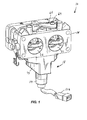
- Fig. 1 is a front perspective view of a gaseous fuel mixing device including a modified carburetor body and an intake unit.
- Fig. 2 is a rear perspective view of the gaseous fuel mixing device of Fig. 1 .
- Fig. 3 is an exploded perspective view of the gaseous fuel mixing device of Fig. 1 .
- Fig. 4 is a rear view of the gaseous fuel mixing device of Fig. 1 .
- Fig. 5 is a top view of the gaseous fuel mixing device of Fig. 1 , with portions removed.
- Fig. 6 is bottom view of the gaseous fuel mixing device of Fig. 1 , with the intake unit removed.
- Fig. 7 is a top view of the intake unit of the gaseous fuel mixing device of Fig. 1 .
- Fig. 8 is a perspective view illustrating the modified carburetor body separated from the intake unit of Fig. 1 , illustrating the mixing device operating in a first condition with a first type of fuel.
- Fig. 9 is a perspective view illustrating the modified carburetor body separated from the intake unit of Fig. 1 , illustrating the mixing device operating in a second condition with the first type of fuel.
- Fig. 10 is a perspective view illustrating the modified carburetor body separated from the intake unit of Fig. 1 , illustrating the mixing device operating in the first condition with a second type of fuel.
- Fig. 11 is a perspective view illustrating the modified carburetor body separated from the intake unit of Fig. 1 , illustrating the mixing device operating in the second condition with the second type of fuel.
- Fig. 12 is a cross-sectional view of the gaseous fuel mixing device of Fig. 1 , along line 12-12 in Fig. 4 , illustrating the mixing device operating in the first condition with the first type of fuel.
- Fig. 13 is a cross-sectional view of the gaseous fuel mixing device of Fig. 1 , along the same line 12-12 in Fig. 4 , illustrating the mixing device operating in the second condition with the first type of fuel.
- Fig. 14 is a cross-sectional view of the gaseous fuel mixing device of Fig. 1 , along the same line 12-12 in Fig. 4 , illustrating the mixing device operating in the first condition with the second type of fuel.
- Fig. 15 is a cross-sectional view of the gaseous fuel mixing device of Fig. 1 , along the same line 12-12 in Fig. 4 , illustrating the mixing device operating in the second condition with the second type of fuel.
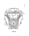
- Fig. 16 is a front view of an engine incorporating the gaseous fuel mixing device of Fig. 1 .
- Fig. 17 is a schematic of the intake unit of Fig. 1 including a fuel selector valve.
- Figs. 1-3 illustrate a mixing device 10 that includes a modified carburetor body 14 and a reservoir or intake unit 18.
- the mixing device 10 is configured for use with a two-cylinder, horizontal shaft engine 12, and may be disposed beneath a removable cover 21 of the engine 12 (see FIG. 16 ).
- the mixing device 10 may be utilized with a vertical shaft engine.
- the engine 12 is powered by a gaseous fuel such as, for example, liquid propane (LP) or natural gas (NG).
- LP liquid propane
- NG natural gas
- the gaseous fuel engine 12 may be used in a standby generator.
- the gaseous fuel engine 12 may be used in other suitable gaseous fuel applications, such as a lawnmower.
- the mixing device 10 may be configured for use with a different number of cylinders, such as a single cylinder engine.
- a first regulator may be positioned upstream of the mixing device 10 to regulate the pressure of the gaseous fuel entering the mixing device 10.
- the first regulator may be positioned near an LP tank or a NG source to reduce the relatively high pressure of the gaseous fuel prior to the gaseous fuel flowing into the intake unit 18.
- the first regulator may be configured to facilitate altering the fuel from a high-pressure liquid state to a lower-pressure gaseous state.
- a second regulator (not shown) may be positioned on or adjacent the engine 12 to reduce the pressure of the gaseous fuel as it enters the mixing device 10.
- the carburetor body 14 is from an existing V-twin carburetor, originally configured for use with a liquid fuel (e.g., gasoline), that is modified for use with a gaseous fuel.
- a liquid fuel e.g., gasoline
- the carburetor body 14 may be modified by closing off (e.g., blocking, plugging, etc.) unneeded passageways, removing a fuel bowl and float (not shown), and adding an input/chamber component (e.g., the intake unit 18) in place of the fuel bowl for use with the gaseous fuel mixing device 10.
- the carburetor body 14 includes a first air/fuel or intake passageway 22, a second air/fuel or intake passageway 26, and respective throttle plates or valves 30 pivotably coupled for rotation in the intake passageways 22, 26.
- the intake passageways 22, 26 are in communication with an external air source and the intake unit 18 to provide the gaseous fuel to corresponding cylinders of the engine 12.
- the throttle valves 30 are responsive to actuation by an engine governor or are manually actuated by a user, and rotate between an opened and a closed position to adjust the amount of gaseous fuel supplied to the engine 12 in accordance with the engine speed or the applied load.
- the gaseous fuel is drawn into the intake passageways 22, 26 by a vacuum pulse generated as air flows through a venturi 32 (i.e., the smaller diameter portion) of the intake passageways 22, 26 (see FIGS. 12-15 ).
- a vacuum pulse generated as air flows through a venturi 32 (i.e., the smaller diameter portion) of the intake passageways 22, 26 (see FIGS. 12-15 ).
- the throttle valves 30 rotate toward an open position to allow more air to flow through the intake passageways 22, 26, creating a larger vacuum pulse and drawing more fuel into the intake passageways 22, 26.
- the throttle valves 30 rotate toward a closed position to restrict the air flow through the intake passageways 22, 26, creating a smaller vacuum pulse and drawing less fuel into the intake passageways 22, 26.
- the original, unmodified carburetor body also includes various passageways for air and/or fuel flow.
- some of the passageways have been blocked off or plugged such that the carburetor body 14 is suitably modified for use with a gaseous fuel.
- passageways that have been blocked are generally indicated by an "X".
- the passageways and holes may be plugged with epoxy or plugs, by removing corresponding core pins in the die used to form the original carburetor body, or by eliminating a machining process for the carburetor body.
- the carburetor body Prior to modification, the carburetor body includes a main liquid (e.g., gasoline) fuel passageway or inlet 34 exposed to an exterior surface 36 of the carburetor body 14, and internal vents 38 (see Fig. 6 ).
- the main gasoline fuel inlet 34 supplies gasoline to the fuel bowl in a gasoline engine.
- the main gasoline fuel inlet 34 is initially defined by a core pin in the die for the carburetor body and then machined (e.g., drilled) once the carburetor body is removed from the die.
- the main gasoline fuel inlet 34 is plugged (e.g., by using an epoxy, etc.) because the gaseous fuel engine does not require gasoline for operation.
- the internal vents 38 vent the airspace above the liquid fuel in the original carburetor fuel bowl.
- the internal vents 38 are formed such that one end ( Fig. 4 ) is downstream of an air cleaner/filter and the other end ( Fig. 6 ) is in the airspace above the fuel in the fuel bowl.
- the original carburetor body also includes a provision 42 for an additional or alternative internal vent.
- the provision 42 may be completely drilled through for use in lieu of the internal vents 38. However, in the illustrated embodiment, no fuel bowl is present and thus the internal vents 38 are not needed. Therefore, both the existing internal vents 38 and the provision 42 for an internal vent are blocked off in the modified carburetor body 14.
- the carburetor body includes nozzles extending into the first and second intake passageways 22, 26 and emulsion tubes extending into the fuel bowl.
- the nozzles are positioned within corresponding nozzle passageways 46 and are typically made of brass. The nozzles carry fuel between the fuel bowl and the intake passageways 22, 26 to supply the fuel during operation of the engine.
- the nozzles are removed and the nozzle passageways 46 are plugged. In some embodiments, the nozzle passageways 46 remain unplugged, but are recalibrated (e.g., resized) for use with gaseous fuels.
- the emulsion tubes are made of brass and extend from corresponding emulsion passageways 50 positioned between the intake passageways 22, 26 ( Fig. 4 ).
- air enters the emulsion tubes and mixes with the liquid fuel. The mixture of fuel and air is then drawn through the nozzles and into the intake passageways 22, 26.
- the emulsion tubes are removed and the emulsion passageways 50 are plugged because the fuel used with the illustrated modified carburetor body 14 is already a gas and does not require additional air to reach a gaseous state.
- the original carburetor body also includes mixing chambers 54, or progression slots or holes, for use at idle speeds.
- the mixing chambers 54 communicate with air bleed inlets 58, fuel bleed inlets 62 ( Fig. 6 ), and idle holes or slots 66.
- the air bleed inlets 58 provide entry points for air to enter the mixing chambers 54 and break up (i.e., vaporize) fuel entering the mixing chambers 54 through the fuel bleed inlets 62. This relatively small mixture of air and fuel then enters the first and second intake passageways 22, 26 through the corresponding idle holes or slots 66 so that the engine continues to run at idle speeds.
- the fuel bleed inlets 62 are recalibrated and the air bleed inlets 58 are blocked (see Fig. 4 ) because the gaseous fuel does not require additional air.
- the idle holes 66 are recalibrated for use with the gaseous fuel.
- the mixing chambers 54 are entirely or partially filled such that only a small, direct passageway exists between the fuel bleed inlets 62 and the idle holes 66.
- the mixing device 10 includes a gasket 67 and a plate 68 coupled to the carburetor body 14 to seal the gasket 67 against the carburetor body 14.
- the gasket 67 and plate 68 are positioned over the mixing chambers 54 to substantially prevent entry of additional air into the mixing chambers 54.
- fasteners e.g., screws 69, etc.
- the plate 68 may be coupled to the carburetor body 14 in any of a number of different ways (e.g., by welding, brazing, by using adhesives, etc.).
- gaseous fuel passageways or apertures 70 are machined (e.g., drilled or bored) near an outer periphery of the carburetor body 14 during the process of modifying the carburetor body 14.
- the apertures 70 include respective inlets 71, each exposed to the exterior surface 36 of the carburetor body 14, and respective outlets 72 exposed to the respective intake passageways 22, 26.
- the apertures 70 are appropriately sized to allow gaseous fuel to flow from the intake unit 18 and into the intake passageways 22, 26.
- the apertures 70 replace the flow passageway previously provided by the nozzle passageways 46.
- the apertures 70 may be omitted and the nozzle passageways 46 may be recalibrated for use with gaseous fuels.
- the intake unit 18 includes a housing 74, a gaseous fuel chamber 78 at least partially defined in the housing 74, a hose connection 82 extending from the housing 74 at least partially defining a gaseous fuel inlet 84 in the housing 74 (see Figs. 12-15 ), a first jet 86 fluidly communicating the inlet 84 and the fuel chamber 78, and a second jet 90 fluidly communicating the inlet 84 and the fuel chamber 78.
- each of the jets 86, 90 is a separate and distinct component from the housing 74.
- each of the jets 86, 90 is generally tubular (see Figs.
- the jets 86, 90 are made from metal (e.g., brass), and are press-fit within respective apertures 93 in the housing 74.
- the jets 86, 90 may be omitted, and the respective apertures 93 in the housing 74 may be sized according to the orifices 92 in the jets 86, 90 to provide a calibrated flow of gaseous fuel from the inlet 84 to the fuel chamber 78.
- the fuel chamber 78 may be omitted from the intake unit 18, such that gaseous fuel is delivered to the carburetor body 14 via conduits interconnecting the carburetor body 14 and the respective jets 86, 90.
- the intake unit 18 also includes a flange 94 having apertures 98 configured to align with corresponding apertures 102 in the carburetor body 14 (see Fig. 6 ).
- Fasteners e.g., a screw 104, a bolt, etc.
- the intake unit 18 is machined or cast from aluminum.
- the intake unit 18 may be composed of another suitable material or combination of materials such as, for example, plastic, steel, ceramic, or the like.
- the fuel chamber 78 is a reservoir to temporarily hold a supply of gaseous fuel.
- the hose connection 82 extends from the intake unit 18 and is configured to communicate with a LP supply or NG supply.
- the hose connection 82 may include threads, barbs or a quick-connect/disconnect coupler to facilitate coupling with the gaseous fuel source.
- the hose connection 82 is a separate piece that is threaded, welded, press-fit, brazed, or cast, or otherwise attached to the housing 74.
- the hose connection 82 may be formed or machined as a single component with the housing 74.
- the first and second jets 86, 90 are positioned within the fuel chamber 78 to allow gaseous fuel entering the intake unit 18 through the hose connection 82 to be temporarily stored within the fuel chamber 78.
- both jets 86, 90 are configured to be open and supply NG to the fuel chamber 78.
- only one jet e.g., the first jet 86
- the jets 86, 90 may include different sized orifices 92, and are calibrated such that the jet 86 used to supply LP supplies the correct amount for optimal efficiency and performance.
- the intake unit 18 includes a selector valve 106 to selectively close one of the jets (e.g., the second jet 90).
- a solenoid or lever 110 is coupled to the valve 106 to actuate the valve 106.
- the valve 106 may be automatically or manually operated to switch between NG and LP applications.
- the valve 106 may be set at an open or closed position during manufacture of the intake unit 18.
- one of the jets (e.g., jet 90) and the selector valve 106 could be eliminated if the mixing device 10 is designed to be used with a single type of fuel (e.g., LP).
- a solenoid 114 is utilized to move the valve 106 relative to the jet 90 to control the flow of gaseous fuel from the inlet 84 to the fuel chamber 78 via the jet 90 (see Fig. 3 ).
- the solenoid 114 includes a plunger 118 upon which the valve 106 is supported, and a biasing member (e.g., a compression spring 122) biasing the plunger 118 and valve 106 toward the jet 90.
- the solenoid 114 is energized to move the plunger 118 and the valve 106 away from the jet 90, against the bias of the spring 122, to substantially open the jet 90 (see Figs. 12 and 13 ).
- the solenoid 114 may be configured such that the valve 106 is biased away from the jet 90, and energizing the solenoid 114 moves the plunger 118 and the valve 106 toward the jet 90, against the bias of a tension spring, to substantially close the jet 90.
- the solenoid 114 includes a wiring harness 126 configured to be selectively connected to a source of electricity.
- the engine 12 must also be connected to the source ofNG.
- the individual need only leave the wiring harness 126 unplugged to configure the engine 12 for operation with LP (in addition to connecting the engine 12 to the source of LP).
- the spring 122 biases the valve 106 against the jet 90 to substantially close the jet 90.
- Incorporating the solenoid 114 and valve 106 with the intake unit 18 allows the mixing device 10 to be packaged on the engine 12 beneath one or more shrouds or housings (e.g., cover 21; see Fig. 16 ), where it might otherwise be difficult to gain access to change or otherwise modify the structure of the intake unit 18 at the installation site to adapt the engine 12 to operate using either a NG fuel source or a LP fuel source.
- an idle jet housing 130 is positioned between the intake unit 18 and the carburetor body 14.
- the idle jet housing 130 includes an upper surface 134 that, when the intake unit 18 is coupled to the carburetor body 14, engages the exterior surface 36 of the carburetor body 14 to define a gaseous fuel sub-chamber 138 within the fuel chamber 78.
- the idle jet housing 130 is a separate and distinct component from the intake unit 18, and is coupled to the intake unit 18 via a plurality of fasteners (e.g., screws 142, etc.).
- the idle jet housing 1.30 may be coupled to the intake unit 18 in any of a number of different ways (e.g., by welding, brazing, by using adhesives, etc.).
- the idle jet housing 130 may be integrally formed as a single piece with the housing 74 of the intake unit 18.
- the idle jet housing 130 substantially surrounds the fuel bleed inlets 62, such that the fuel bleed inlets 62 are not directly exposed to the fuel chamber 78, but instead are directly exposed to the sub-chamber 138 in the idle jet housing 130.
- the idle jet housing 130 includes an orifice 146 in a bottom surface 150 of the idle jet housing 130 in facing relationship with the jet 90, and another orifice 154 in a side surface 158 of the idle jet housing 130. As a result, gaseous fuel in the fuel chamber 78 must pass through the respective orifices 146, 154 to enter the sub-chamber 138 and the fuel bleed inlets 62.
- the orifices 146, 154 may be calibrated to meter different amounts of gaseous fuel into the sub-chamber 138 (e.g., by having different diameters). Further, each of the orifices 146, 1.54 includes a diameter, and therefore a cross-sectional area, less than that of the orifices 92 defined by the jets 86, 90.
- each of the orifices 146, 154 is defined by a respective jet 162, 166 coupled to the idle jet housing 130. Specifically, each of the jets 162, 166 is a separate and distinct component from the idle jet housing 130, and is threadably connected to the idle jet housing 130. Alternatively, the jets 162, 166 may be omitted, and each of the orifices 146, 154 may be defined by respective apertures created in the idle jet housing 130.
- the jet 162 is substantially coaxial with the jet 90 in the intake unit 18.
- a tip 170 of the plunger 118 is engageable with the jet 162 to substantially close the jet 162 at about the same time that the jet 90 is closed by the valve 106 (see Figs. 14 and 15 ).
- the plunger tip 170 may include any of a number of different shapes (e.g., a tapered shape) to facilitate sealing the plunger tip 170 against the jet 162 to substantially prevent flow of gaseous fuel through the jet 162 and into the sub-chamber 138.
- a user rotates the throttle valves 30 relative to the intake passageways 22, 26 (e.g., by pushing a pedal, pulling a lever, etc.), or the engine governor automatically positions the throttle valves 30 to adjust the air flow through the intake passageways 22, 26.
- the throttle valves 30 are substantially parallel to the direction of air flow in the intake passageways 22, 26 (as shown in Figs. 12 and 14 )
- the greatest amount of air flows through the intake passageways 22, 26.
- the flow is slightly reduced at the venturis 32. At normal operating speeds, this creates a vacuum pulse that is capable of drawing gaseous fuel from the intake unit 18 into the intake passageways 22, 26 via the respective passageways or apertures 70.
- the gaseous fuel mixes and flows with the air toward the first and second cylinders of the engine 12 where it is combusted to power the engine 12.
- Figs. 8 and 12 illustrate the mixing device 10 operating in a main or normal running circuit.
- the main circuit is used when the engine 12 is in a normal operating condition (e.g., full throttle), and not simply running at an idle speed.
- the mixing device 10 operates according to this main circuit when the vacuum pulses in the modified carburetor body 14 are sufficiently strong to draw gaseous fuel through the apertures 70 in fluid flow communication with the fuel chamber 78.
- gaseous fuel flows through the hose connection 82, through the first and/or second jets 86, 90, and into the fuel chamber 78 of the intake unit 18.
- the gaseous fuel in the fuel chamber 78 is drawn through the large apertures 70 and into the corresponding intake passageways 22, 26 (see Fig. 12 ).
- the gaseous fuel flows to the respective cylinders of the engine 12 for combustion, based upon the magnitude of the respective individual vacuum pulses generated by each cylinder during the intake stroke of the engine. If the individual vacuum pulses in the intake passageways 22, 26 differ, different amounts of gaseous fuel are drawn from the intake unit 18 into the respective passageways 22, 26 to suit the individual fuel demand for each of the cylinders in the engine 12.
- the valve 106 is open such that the gaseous fuel flows through both jets 86, 90. Such a configuration is desirable for NG applications. In other embodiments, the valve 106 may be closed such that the gaseous fuel can only flow through the first jet 86 (see Fig. 14 ). Such a configuration is desirable for LP applications. For single fuel applications, the valve 106 may be omitted.
- Figs. 9 and 13 illustrate the mixing device 10 operating in an idle or slow circuit, in which the throttle valves 30 are substantially closed.
- the idle circuit is used when the vacuum pulses in the modified carburetor body 14 and mixing device 10 are not strong enough to draw gaseous fuel through the apertures 70, but instead draw the gaseous fuel through the fuel bleed inlets 62. While the engine 12 is using the idle circuit at idle speed, the individual vacuum pulses in the mixing device 10 draw the gaseous fuel through the smaller fuel bleed inlets 62 in a sufficient quantity to keep the engine 12 running at an idle speed.
- the gaseous fuel in the fuel passageway 78 flows through the jets 162, 166, into the sub-chamber 138, through the fuel bleed inlets 62, through the mixing chambers 54 and idle holes 66, and into the intake passageways 22, 26 (see Fig. 13 ).
- the solenoid 114 is energized to maintain the valve 106 in a position spaced from the jet 90 such that both jets 86, 90 supply gaseous fuel to the fuel chamber 78, which, as discussed above, is desirable for NG applications.
- the solenoid 114 may be de-energized to allow the valve 106 to seat against and close the jet 90, and allow the plunger tip 170 to seat against and close the jet 162 in the idle jet housing 130, such that the gaseous fuel only flows through the first jet 86 and the jet 166 in the idle jet housing 130, which is desirable for LP applications (see Fig. 15 ).
- the valve 106 may be omitted.
- the mixing device 10 provides a low-cost structure and method to modify an existing carburetor body for use with a gaseous fuel. More particularly, unneeded passageways in the existing carburetor body may be quickly, inexpensively, and easily blocked without requiring a new mixing device body to be designed and tooled from scratch.
- the existing carburetor body may be fitted with a low-cost, easy to manufacture intake unit to further minimize costs. Gaseous fuel engines may, thereby, become more available while minimizing additional costs that are generated when manufacturing specialized components.
- An important aspect of the present invention is that the individual vacuum pulse of each individual cylinder determines or regulates the amount of fuel drawn in by that cylinder without the need for a separate regulator or injector, and without an electronic controller.
- Each cylinder draws in an individualized quantity of fuel during its own intake stroke.
Landscapes
- Engineering & Computer Science (AREA)
- Chemical & Material Sciences (AREA)
- Combustion & Propulsion (AREA)
- Mechanical Engineering (AREA)
- General Engineering & Computer Science (AREA)
- Chemical Kinetics & Catalysis (AREA)
- General Chemical & Material Sciences (AREA)
- Oil, Petroleum & Natural Gas (AREA)
- Output Control And Ontrol Of Special Type Engine (AREA)
- Gas Burners (AREA)
Abstract
Description
- This application claims priority to
U.S. Provisional Patent Application Serial No. 60/931,84.3 filed on May 25, 2007 - The present invention relates to a mixing device for gaseous fuel. More particularly, the present invention relates to a gaseous fuel mixing device using a modified carburetor body.
- Typically, a liquid fuel carburetor includes at least one air intake passageway having a venturi and a fuel bowl that is configured to temporarily store a supply of liquid fuel. The venturi is in communication with the fuel bowl such that, as air flows through the venturi, liquid fuel is drawn from the fuel bowl and into the intake passageway. The fuel mixes with the air to become a vapor and flows through the intake passageway or throat to a cylinder of an internal combustion engine. The vaporized fuel is combusted in the cylinder to drive the engine.
- Due to governmental regulations on emissions from small engines, it has become more desirable to power internal combustion engines with gaseous fuels (e.g., liquid propane and natural gas). However, these engines do not require typical carburetors that are configured to deliver vaporized gasoline to the cylinder. Rather, these engines require mixing devices that are capable of mixing the fuel with air, and supplying the mixture to the engine.
- The present invention provides, in one aspect, a mixing device for use with a gaseous fuel internal combustion engine. To reduce cost, the mixing device uses a modified, existing carburetor body and a gaseous fuel reservoir or intake unit. The modified carburetor body includes an air intake passageway, a throttle valve coupled for rotation in the intake passageway, and at least one passageway in communication between the intake unit and the intake passageway. The intake unit includes a fuel chamber, a first jet, and an optional second jet. The intake unit may also include a valve operable to selectively close the second jet for different gaseous fuels. In other embodiments, the mixing device may have one or two jets, or could be designed for use with a single fuel (LP or NG) and thus would not require a selector valve.
- The present invention provides, in another aspect, a gaseous fuel mixing device including a body including an air/fuel passageway and a gaseous fuel passageway in fluid communication with the air/fuel passageway, a throttle valve pivotably coupled to the body and positioned in the air/fuel passageway, and an intake unit coupled to the body. The intake unit includes an inlet configured to be fluidly connected with a source of gaseous fuel, a first jet fluidly communicating the inlet and the gaseous fuel passageway, a second jet selectively fluidly communicating the inlet and the gaseous fuel passageway, and a selector valve operable to control a flow of gaseous fuel through the second jet.
- The present invention provides, in yet another aspect, a gaseous fuel mixing device including a body having a first air/fuel passageway, a second air/fuel passageway, a first gaseous fuel passageway in fluid communication with the first air/fuel passageway, a second gaseous fuel passageway in fluid communication with the second air/fuel passageway, a first throttle valve pivotably coupled to the body and positioned in the first air/fuel passageway, a second throttle valve pivotably coupled to the body and positioned in the second air/fuel passageway, and an intake unit coupled to the body and in fluid communication with a source of gaseous fuel. Each of the first and second gaseous fuel passageways is configured to draw an amount of gaseous fuel, based upon individual demand of fuel through the respective first and second air/fuel passageways, from the intake unit..
- The present invention provides, in a further aspect, a gaseous fuel mixing device including a modified carburetor body, originally configured for use with a liquid fuel, having an air/fuel passageway, a gaseous fuel passageway having an inlet in communication with an exterior of the body and an outlet in communication with the air/fuel passageway, a closed liquid fuel passageway, a throttle valve pivotably coupled to the carburetor body and positioned in the air/fuel passageway, and an intake unit coupled to the carburetor body. The intake unit is configured to deliver gaseous fuel to the gaseous fuel passageway in the carburetor body.
- The present invention provides, in another aspect, a method of converting a carburetor from operating using a liquid fuel to operating using a gaseous fuel. The method includes providing a carburetor body including an air/fuel passageway, creating a gaseous fuel passageway through a portion of the body to fluidly communicate the gaseous fuel passageway with the air/fuel passageway, and closing a liquid fuel passageway in the body.
- Other aspects of the invention will become apparent by consideration of the detailed description and accompanying drawings.
-
Fig. 1 is a front perspective view of a gaseous fuel mixing device including a modified carburetor body and an intake unit. -
Fig. 2 is a rear perspective view of the gaseous fuel mixing device ofFig. 1 . -
Fig. 3 is an exploded perspective view of the gaseous fuel mixing device ofFig. 1 . -
Fig. 4 is a rear view of the gaseous fuel mixing device ofFig. 1 . -
Fig. 5 is a top view of the gaseous fuel mixing device ofFig. 1 , with portions removed. -
Fig. 6 is bottom view of the gaseous fuel mixing device ofFig. 1 , with the intake unit removed. -
Fig. 7 is a top view of the intake unit of the gaseous fuel mixing device ofFig. 1 . -
Fig. 8 is a perspective view illustrating the modified carburetor body separated from the intake unit ofFig. 1 , illustrating the mixing device operating in a first condition with a first type of fuel. -
Fig. 9 is a perspective view illustrating the modified carburetor body separated from the intake unit ofFig. 1 , illustrating the mixing device operating in a second condition with the first type of fuel. -
Fig. 10 is a perspective view illustrating the modified carburetor body separated from the intake unit ofFig. 1 , illustrating the mixing device operating in the first condition with a second type of fuel. -
Fig. 11 is a perspective view illustrating the modified carburetor body separated from the intake unit ofFig. 1 , illustrating the mixing device operating in the second condition with the second type of fuel. -
Fig. 12 is a cross-sectional view of the gaseous fuel mixing device ofFig. 1 , along line 12-12 inFig. 4 , illustrating the mixing device operating in the first condition with the first type of fuel. -
Fig. 13 is a cross-sectional view of the gaseous fuel mixing device ofFig. 1 , along the same line 12-12 inFig. 4 , illustrating the mixing device operating in the second condition with the first type of fuel. -
Fig. 14 is a cross-sectional view of the gaseous fuel mixing device ofFig. 1 , along the same line 12-12 inFig. 4 , illustrating the mixing device operating in the first condition with the second type of fuel. -
Fig. 15 is a cross-sectional view of the gaseous fuel mixing device ofFig. 1 , along the same line 12-12 inFig. 4 , illustrating the mixing device operating in the second condition with the second type of fuel. -
Fig. 16 is a front view of an engine incorporating the gaseous fuel mixing device ofFig. 1 . -
Fig. 17 is a schematic of the intake unit ofFig. 1 including a fuel selector valve. - Before any embodiments of the invention are explained in detail, it is to be understood that the invention is not limited in its application to the details of construction and the arrangement of components set forth in the following description or illustrated in the following drawings. The invention is capable of other embodiments and of being practiced or of being carried out in various ways. Also, it is to be understood that the phraseology and terminology used herein are for the purpose of description and should not be regarded as limiting. The use of "including," "comprising," or "having" and variations thereof herein is meant to encompass the items listed thereafter and equivalents thereof as well as additional items. Unless specified or limited otherwise, the terms "mounted," "connected," "supported," and "coupled" and variations thereof are used broadly and encompass both direct and indirect mountings, connections, supports, and couplings. Further, "connected" and "coupled" are not restricted to physical or mechanical connections or couplings.
-
Figs. 1-3 illustrate amixing device 10 that includes a modifiedcarburetor body 14 and a reservoir orintake unit 18. In the illustrated embodiment, themixing device 10 is configured for use with a two-cylinder,horizontal shaft engine 12, and may be disposed beneath aremovable cover 21 of the engine 12 (seeFIG. 16 ). Alternatively, themixing device 10 may be utilized with a vertical shaft engine. Theengine 12 is powered by a gaseous fuel such as, for example, liquid propane (LP) or natural gas (NG). In some embodiments, thegaseous fuel engine 12 may be used in a standby generator. In other embodiments, thegaseous fuel engine 12 may be used in other suitable gaseous fuel applications, such as a lawnmower. Additionally, themixing device 10 may be configured for use with a different number of cylinders, such as a single cylinder engine. - In some embodiments, a first regulator (not shown) may be positioned upstream of the
mixing device 10 to regulate the pressure of the gaseous fuel entering themixing device 10. In one embodiment, the first regulator may be positioned near an LP tank or a NG source to reduce the relatively high pressure of the gaseous fuel prior to the gaseous fuel flowing into theintake unit 18. For example, the first regulator may be configured to facilitate altering the fuel from a high-pressure liquid state to a lower-pressure gaseous state. Additionally or alternatively, a second regulator (not shown) may be positioned on or adjacent theengine 12 to reduce the pressure of the gaseous fuel as it enters themixing device 10. - As shown in
Figs. 1-3 , thecarburetor body 14 is from an existing V-twin carburetor, originally configured for use with a liquid fuel (e.g., gasoline), that is modified for use with a gaseous fuel. For example, thecarburetor body 14 may be modified by closing off (e.g., blocking, plugging, etc.) unneeded passageways, removing a fuel bowl and float (not shown), and adding an input/chamber component (e.g., the intake unit 18) in place of the fuel bowl for use with the gaseousfuel mixing device 10. - With reference to
Fig. 1 , thecarburetor body 14 includes a first air/fuel orintake passageway 22, a second air/fuel orintake passageway 26, and respective throttle plates orvalves 30 pivotably coupled for rotation in theintake passageways intake unit 18 to provide the gaseous fuel to corresponding cylinders of theengine 12. Thethrottle valves 30 are responsive to actuation by an engine governor or are manually actuated by a user, and rotate between an opened and a closed position to adjust the amount of gaseous fuel supplied to theengine 12 in accordance with the engine speed or the applied load. - In the illustrated embodiment, the gaseous fuel is drawn into the
intake passageways intake passageways 22, 26 (seeFIGS. 12-15 ). When theengine 12 requires more fuel, thethrottle valves 30 rotate toward an open position to allow more air to flow through theintake passageways intake passageways engine 12 requires less fuel, thethrottle valves 30 rotate toward a closed position to restrict the air flow through theintake passageways intake passageways - The original, unmodified carburetor body also includes various passageways for air and/or fuel flow. In the illustrated embodiment, some of the passageways have been blocked off or plugged such that the
carburetor body 14 is suitably modified for use with a gaseous fuel. In the figures, passageways that have been blocked are generally indicated by an "X". The passageways and holes may be plugged with epoxy or plugs, by removing corresponding core pins in the die used to form the original carburetor body, or by eliminating a machining process for the carburetor body. - Prior to modification, the carburetor body includes a main liquid (e.g., gasoline) fuel passageway or
inlet 34 exposed to anexterior surface 36 of thecarburetor body 14, and internal vents 38 (seeFig. 6 ). The maingasoline fuel inlet 34 supplies gasoline to the fuel bowl in a gasoline engine. The maingasoline fuel inlet 34 is initially defined by a core pin in the die for the carburetor body and then machined (e.g., drilled) once the carburetor body is removed from the die. In the illustrated embodiment, the maingasoline fuel inlet 34 is plugged (e.g., by using an epoxy, etc.) because the gaseous fuel engine does not require gasoline for operation. - The
internal vents 38 vent the airspace above the liquid fuel in the original carburetor fuel bowl. Theinternal vents 38 are formed such that one end (Fig. 4 ) is downstream of an air cleaner/filter and the other end (Fig. 6 ) is in the airspace above the fuel in the fuel bowl. In some embodiments, the original carburetor body also includes aprovision 42 for an additional or alternative internal vent. Theprovision 42 may be completely drilled through for use in lieu of the internal vents 38. However, in the illustrated embodiment, no fuel bowl is present and thus theinternal vents 38 are not needed. Therefore, both the existinginternal vents 38 and theprovision 42 for an internal vent are blocked off in the modifiedcarburetor body 14. - In addition, prior to modification, the carburetor body includes nozzles extending into the first and
second intake passageways corresponding nozzle passageways 46 and are typically made of brass. The nozzles carry fuel between the fuel bowl and theintake passageways carburetor body 14, the nozzles are removed and the nozzle passageways 46 are plugged. In some embodiments, the nozzle passageways 46 remain unplugged, but are recalibrated (e.g., resized) for use with gaseous fuels. - The emulsion tubes are made of brass and extend from corresponding emulsion passageways 50 positioned between the
intake passageways 22, 26 (Fig. 4 ). In a standard liquid fuel carburetor, air enters the emulsion tubes and mixes with the liquid fuel. The mixture of fuel and air is then drawn through the nozzles and into theintake passageways carburetor body 14 used with the present invention, the emulsion tubes are removed and the emulsion passageways 50 are plugged because the fuel used with the illustrated modifiedcarburetor body 14 is already a gas and does not require additional air to reach a gaseous state. - As shown in
Fig. 5 , the original carburetor body also includes mixingchambers 54, or progression slots or holes, for use at idle speeds. The mixingchambers 54 communicate withair bleed inlets 58, fuel bleed inlets 62 (Fig. 6 ), and idle holes orslots 66. In a typical carburetor, theair bleed inlets 58 provide entry points for air to enter the mixingchambers 54 and break up (i.e., vaporize) fuel entering the mixingchambers 54 through thefuel bleed inlets 62. This relatively small mixture of air and fuel then enters the first andsecond intake passageways slots 66 so that the engine continues to run at idle speeds. In the illustrated embodiment of the modifiedcarburetor body 14, thefuel bleed inlets 62 are recalibrated and theair bleed inlets 58 are blocked (seeFig. 4 ) because the gaseous fuel does not require additional air. In addition, theidle holes 66 are recalibrated for use with the gaseous fuel. In some embodiments, the mixingchambers 54 are entirely or partially filled such that only a small, direct passageway exists between thefuel bleed inlets 62 and the idle holes 66. - As shown in
Fig. 3 , the mixingdevice 10 includes agasket 67 and aplate 68 coupled to thecarburetor body 14 to seal thegasket 67 against thecarburetor body 14. Specifically, thegasket 67 andplate 68 are positioned over the mixingchambers 54 to substantially prevent entry of additional air into the mixingchambers 54. In the illustrated construction of the mixingdevice 10, fasteners (e.g., screws 69, etc.) are utilized to couple theplate 68 to thecarburetor body 14. Alternatively, theplate 68 may be coupled to thecarburetor body 14 in any of a number of different ways (e.g., by welding, brazing, by using adhesives, etc.). - Referring to
Fig. 6 , gaseous fuel passageways orapertures 70 are machined (e.g., drilled or bored) near an outer periphery of thecarburetor body 14 during the process of modifying thecarburetor body 14. Theapertures 70 includerespective inlets 71, each exposed to theexterior surface 36 of thecarburetor body 14, andrespective outlets 72 exposed to therespective intake passageways apertures 70 are appropriately sized to allow gaseous fuel to flow from theintake unit 18 and into theintake passageways apertures 70 replace the flow passageway previously provided by thenozzle passageways 46. As discussed above, in some embodiments, theapertures 70 may be omitted and thenozzle passageways 46 may be recalibrated for use with gaseous fuels. - As shown in
Fig. 3 , theintake unit 18 includes ahousing 74, agaseous fuel chamber 78 at least partially defined in thehousing 74, ahose connection 82 extending from thehousing 74 at least partially defining agaseous fuel inlet 84 in the housing 74 (seeFigs. 12-15 ), afirst jet 86 fluidly communicating theinlet 84 and thefuel chamber 78, and asecond jet 90 fluidly communicating theinlet 84 and thefuel chamber 78. In the illustrated construction of theintake unit 18, each of thejets housing 74. Specifically, each of thejets Figs. 12-15 ) and includes anorifice 92 calibrated for use with different gaseous fuels (e.g., NG or LP). In addition, thejets respective apertures 93 in thehousing 74. Alternatively, thejets respective apertures 93 in thehousing 74 may be sized according to theorifices 92 in thejets inlet 84 to thefuel chamber 78. As a further alternative, thefuel chamber 78 may be omitted from theintake unit 18, such that gaseous fuel is delivered to thecarburetor body 14 via conduits interconnecting thecarburetor body 14 and therespective jets - As shown in
Fig. 3 , theintake unit 18 also includes aflange 94 havingapertures 98 configured to align withcorresponding apertures 102 in the carburetor body 14 (seeFig. 6 ). Fasteners (e.g., ascrew 104, a bolt, etc.) are utilized to couple theintake unit 18 to thecarburetor body 14. In the illustrated embodiment, theintake unit 18 is machined or cast from aluminum. In other embodiments, theintake unit 18 may be composed of another suitable material or combination of materials such as, for example, plastic, steel, ceramic, or the like. In the illustrated embodiment, thefuel chamber 78 is a reservoir to temporarily hold a supply of gaseous fuel. - With reference to
Fig. 3 , thehose connection 82 extends from theintake unit 18 and is configured to communicate with a LP supply or NG supply. In some embodiments, thehose connection 82 may include threads, barbs or a quick-connect/disconnect coupler to facilitate coupling with the gaseous fuel source. In the illustrated embodiment, thehose connection 82 is a separate piece that is threaded, welded, press-fit, brazed, or cast, or otherwise attached to thehousing 74. In other embodiments, thehose connection 82 may be formed or machined as a single component with thehousing 74. - With continued reference to
Fig. 3 , the first andsecond jets fuel chamber 78 to allow gaseous fuel entering theintake unit 18 through thehose connection 82 to be temporarily stored within thefuel chamber 78. In NG applications, bothjets fuel chamber 78. In LP applications, only one jet (e.g., the first jet 86) is configured to be open and supply LP to thefuel chamber 78. Thejets sized orifices 92, and are calibrated such that thejet 86 used to supply LP supplies the correct amount for optimal efficiency and performance. - With reference to
Fig. 3 , theintake unit 18 includes aselector valve 106 to selectively close one of the jets (e.g., the second jet 90). As shown schematically inFig. 17 , a solenoid or lever 110 is coupled to thevalve 106 to actuate thevalve 106. As such, thevalve 106 may be automatically or manually operated to switch between NG and LP applications. Alternatively, thevalve 106 may be set at an open or closed position during manufacture of theintake unit 18. Alternatively, one of the jets (e.g., jet 90) and theselector valve 106 could be eliminated if the mixingdevice 10 is designed to be used with a single type of fuel (e.g., LP). - In the illustrated construction of the
intake unit 18, asolenoid 114 is utilized to move thevalve 106 relative to thejet 90 to control the flow of gaseous fuel from theinlet 84 to thefuel chamber 78 via the jet 90 (seeFig. 3 ). Thesolenoid 114 includes aplunger 118 upon which thevalve 106 is supported, and a biasing member (e.g., a compression spring 122) biasing theplunger 118 andvalve 106 toward thejet 90. In operation of theintake unit 18, as will be discussed in greater detail below, thesolenoid 114 is energized to move theplunger 118 and thevalve 106 away from thejet 90, against the bias of thespring 122, to substantially open the jet 90 (seeFigs. 12 and 13 ). Alternatively, thesolenoid 114 may be configured such that thevalve 106 is biased away from thejet 90, and energizing thesolenoid 114 moves theplunger 118 and thevalve 106 toward thejet 90, against the bias of a tension spring, to substantially close thejet 90. - With reference to
Figs. 1-3 , thesolenoid 114 includes awiring harness 126 configured to be selectively connected to a source of electricity. An individual installing, for example, a household electrical generator incorporating theengine 12, need only connect thewiring harness 126 to a battery or other source of electricity (e.g., the electricity generated by an engine alternator or the generator itself) to configure theengine 12 for operation with NG to maintain thevalve 106 displaced or unseated from thejet 90. Of course, theengine 12 must also be connected to the source ofNG. Likewise, the individual need only leave thewiring harness 126 unplugged to configure theengine 12 for operation with LP (in addition to connecting theengine 12 to the source of LP). As a result, thespring 122 biases thevalve 106 against thejet 90 to substantially close thejet 90. Incorporating thesolenoid 114 andvalve 106 with theintake unit 18 allows the mixingdevice 10 to be packaged on theengine 12 beneath one or more shrouds or housings (e.g., cover 21; seeFig. 16 ), where it might otherwise be difficult to gain access to change or otherwise modify the structure of theintake unit 18 at the installation site to adapt theengine 12 to operate using either a NG fuel source or a LP fuel source. - With reference to
Fig. 3 , anidle jet housing 130 is positioned between theintake unit 18 and thecarburetor body 14. Theidle jet housing 130 includes anupper surface 134 that, when theintake unit 18 is coupled to thecarburetor body 14, engages theexterior surface 36 of thecarburetor body 14 to define agaseous fuel sub-chamber 138 within thefuel chamber 78. In the illustrated construction, theidle jet housing 130 is a separate and distinct component from theintake unit 18, and is coupled to theintake unit 18 via a plurality of fasteners (e.g., screws 142, etc.). Alternatively, the idle jet housing 1.30 may be coupled to theintake unit 18 in any of a number of different ways (e.g., by welding, brazing, by using adhesives, etc.). As a further alternative, theidle jet housing 130 may be integrally formed as a single piece with thehousing 74 of theintake unit 18. - With reference to
Figs. 9 and13 , theidle jet housing 130 substantially surrounds thefuel bleed inlets 62, such that thefuel bleed inlets 62 are not directly exposed to thefuel chamber 78, but instead are directly exposed to the sub-chamber 138 in theidle jet housing 130. With continued reference toFig. 13 , theidle jet housing 130 includes anorifice 146 in abottom surface 150 of theidle jet housing 130 in facing relationship with thejet 90, and anotherorifice 154 in aside surface 158 of theidle jet housing 130. As a result, gaseous fuel in thefuel chamber 78 must pass through therespective orifices fuel bleed inlets 62. Theorifices orifices 146, 1.54 includes a diameter, and therefore a cross-sectional area, less than that of theorifices 92 defined by thejets idle jet housing 130, each of theorifices respective jet idle jet housing 130. Specifically, each of thejets idle jet housing 130, and is threadably connected to theidle jet housing 130. Alternatively, thejets orifices idle jet housing 130. - With reference to
Figs. 7 and9 , thejet 162 is substantially coaxial with thejet 90 in theintake unit 18. In operation of theintake unit 18, as will be discussed in greater detail below, atip 170 of theplunger 118 is engageable with thejet 162 to substantially close thejet 162 at about the same time that thejet 90 is closed by the valve 106 (seeFigs. 14 and 15 ). Theplunger tip 170 may include any of a number of different shapes (e.g., a tapered shape) to facilitate sealing theplunger tip 170 against thejet 162 to substantially prevent flow of gaseous fuel through thejet 162 and into the sub-chamber 138. - In operation of the
engine 12, a user rotates thethrottle valves 30 relative to theintake passageways 22, 26 (e.g., by pushing a pedal, pulling a lever, etc.), or the engine governor automatically positions thethrottle valves 30 to adjust the air flow through theintake passageways throttle valves 30 are substantially parallel to the direction of air flow in theintake passageways 22, 26 (as shown inFigs. 12 and14 ), the greatest amount of air flows through theintake passageways intake passageways venturis 32. At normal operating speeds, this creates a vacuum pulse that is capable of drawing gaseous fuel from theintake unit 18 into theintake passageways apertures 70. The gaseous fuel mixes and flows with the air toward the first and second cylinders of theengine 12 where it is combusted to power theengine 12. -
Figs. 8 and12 illustrate the mixingdevice 10 operating in a main or normal running circuit. The main circuit is used when theengine 12 is in a normal operating condition (e.g., full throttle), and not simply running at an idle speed. The mixingdevice 10 operates according to this main circuit when the vacuum pulses in the modifiedcarburetor body 14 are sufficiently strong to draw gaseous fuel through theapertures 70 in fluid flow communication with thefuel chamber 78. - While operating according to the main circuit, gaseous fuel flows through the
hose connection 82, through the first and/orsecond jets fuel chamber 78 of theintake unit 18. The gaseous fuel in thefuel chamber 78 is drawn through thelarge apertures 70 and into the correspondingintake passageways 22, 26 (seeFig. 12 ). From theintake passageways engine 12 for combustion, based upon the magnitude of the respective individual vacuum pulses generated by each cylinder during the intake stroke of the engine. If the individual vacuum pulses in theintake passageways intake unit 18 into therespective passageways engine 12. In the illustrated embodiment, thevalve 106 is open such that the gaseous fuel flows through bothjets valve 106 may be closed such that the gaseous fuel can only flow through the first jet 86 (seeFig. 14 ). Such a configuration is desirable for LP applications. For single fuel applications, thevalve 106 may be omitted. -
Figs. 9 and13 illustrate the mixingdevice 10 operating in an idle or slow circuit, in which thethrottle valves 30 are substantially closed. The idle circuit is used when the vacuum pulses in the modifiedcarburetor body 14 and mixingdevice 10 are not strong enough to draw gaseous fuel through theapertures 70, but instead draw the gaseous fuel through thefuel bleed inlets 62. While theengine 12 is using the idle circuit at idle speed, the individual vacuum pulses in themixing device 10 draw the gaseous fuel through the smallerfuel bleed inlets 62 in a sufficient quantity to keep theengine 12 running at an idle speed. When the idle circuit is in use, the gaseous fuel in thefuel passageway 78 flows through thejets fuel bleed inlets 62, through the mixingchambers 54 andidle holes 66, and into theintake passageways 22, 26 (seeFig. 13 ). In the illustrated embodiment, thesolenoid 114 is energized to maintain thevalve 106 in a position spaced from thejet 90 such that bothjets fuel chamber 78, which, as discussed above, is desirable for NG applications. In other embodiments, thesolenoid 114 may be de-energized to allow thevalve 106 to seat against and close thejet 90, and allow theplunger tip 170 to seat against and close thejet 162 in theidle jet housing 130, such that the gaseous fuel only flows through thefirst jet 86 and thejet 166 in theidle jet housing 130, which is desirable for LP applications (seeFig. 15 ). For single fuel applications, thevalve 106 may be omitted. - The mixing
device 10 provides a low-cost structure and method to modify an existing carburetor body for use with a gaseous fuel. More particularly, unneeded passageways in the existing carburetor body may be quickly, inexpensively, and easily blocked without requiring a new mixing device body to be designed and tooled from scratch. In addition, the existing carburetor body may be fitted with a low-cost, easy to manufacture intake unit to further minimize costs. Gaseous fuel engines may, thereby, become more available while minimizing additional costs that are generated when manufacturing specialized components. - An important aspect of the present invention is that the individual vacuum pulse of each individual cylinder determines or regulates the amount of fuel drawn in by that cylinder without the need for a separate regulator or injector, and without an electronic controller. Each cylinder draws in an individualized quantity of fuel during its own intake stroke.
- Various features of the invention are set forth in the following claims.
Claims (40)
- A gaseous fuel mixing device configured for use with an internal combustion engine, the mixing device comprising:a body including an air/fuel passageway, and a gaseous fuel passageway in fluid communication with the air/fuel passageway;a throttle valve pivotably coupled to the body and positioned in the air/fuel passageway;an intake unit coupled to the body, the intake unit includingan inlet configured to be fluidly connected with a source of gaseous fuel;a first jet fluidly communicating the inlet and the gaseous fuel passageway;a second jet selectively fluidly communicating the inlet and the gaseous fuel passageway; anda selector valve operable to control a flow of gaseous fuel through the second jet.
- The gaseous fuel mixing device of claim 1, wherein the intake unit includes a gaseous fuel chamber in fluid communication with the gaseous fuel passageway, wherein the first jet is configured to transfer gaseous fuel from the inlet to the gaseous fuel chamber, and wherein the second jet is configured to transfer gaseous fuel, upon actuation of the selector valve, from the inlet to the gaseous fuel chamber.
- The gaseous fuel mixing device of claim 2, further comprising an idle jet housing at least partially positioned within the gaseous fuel chamber, wherein the idle jet housing includes a second gaseous fuel chamber in fluid communication with the gaseous fuel passageway, and at least one orifice selectively fluidly communicating the first gaseous fuel chamber in the intake unit with the second gaseous fuel chamber.
- The gaseous fuel mixing device of claim 3, wherein the selector valve is configured to control the flow of gaseous fuel through the second jet and the orifice in the idle jet housing.
- The gaseous fuel mixing device of claim 3, wherein the body includes a second gaseous fuel passageway in fluid communication with the air/fuel passageway, and wherein the second gaseous fuel passageway directly fluidly connects the first gaseous fuel chamber in the intake unit with the air/fuel passageway.
- The gaseous fuel mixing device of claim 5, wherein the second gaseous fuel passageway is configured to receive gaseous fuel from at least one of the first and second jets when the throttle valve is substantially open.
- The gaseous fuel mixing device of claim 5, wherein the first gaseous fuel passageway is configured to receive gaseous fuel from at least one of the first and second jets, via the orifice in the idle jet housing, when the throttle valve is substantially closed.
- The gaseous fuel mixing device of claim 3, wherein the orifice has a cross-sectional area less than a cross-sectional area of the first jet, and wherein the cross-sectional area of the orifice is less than a cross-sectional area of the second jet.
- The gaseous fuel mixing device of claim 1, wherein the selector valve is configured to be moved between a first position, in which the second jet is at least partially closed, and a second position, in which the second jet is substantially open.
- The gaseous fuel mixing device of claim 1, wherein the body includes a second air/fuel passageway and a second gaseous fuel passageway in fluid communication with the second air/fuel passageway, and wherein each of the first and second gaseous fuel passageways is configured to draw an amount of gaseous fuel, based upon individual demand of fuel through the respective first and second air/fuel passageways, from the intake unit.
- The gaseous fuel mixing device of claim 1, wherein the body includes a modified carburetor body originally configured for use with a liquid fuel, wherein the gaseous fuel passageway has an inlet in communication with an exterior of the body and an outlet in communication with the air/fuel passageway, and wherein the body includes a closed liquid fuel passageway.
- A gaseous fuel mixing device configured for use with an internal combustion engine, the mixing device comprising:a body includinga first air/fuel passageway;a second air/fuel passageway;a first gaseous fuel passageway in fluid communication with the first air/fuel passageway;a second gaseous fuel passageway in fluid communication with the second air/fuel passageway;a first throttle valve pivotably coupled to the body and positioned in the first air/fuel passageway;a second throttle valve pivotably coupled to the body and positioned in the second air/fuel passageway; andan intake unit coupled to the body and in fluid communication with a source of gaseous fuel, wherein each of the first and second gaseous fuel passageways is configured to draw an amount of gaseous fuel, based upon individual demand of fuel through the respective first and second air/fuel passageways, from the intake unit.
- The gaseous fuel mixing device of claim 12, wherein the intake unit includesan inlet configured to be fluidly connected with the source of gaseous fuel;a first jet fluidly communicating the inlet with the first and second gaseous fuel passageways;a second jet selectively fluidly communicating the inlet with the first and second gaseous fuel passageways; anda selector valve configured to control a flow of gaseous fuel through the second jet.
- The gaseous fuel mixing device of claim 13, wherein the intake unit includes a gaseous fuel chamber in fluid communication with the first and second gaseous fuel passageways, wherein the first jet is configured to transfer gaseous fuel from the inlet to the gaseous fuel chamber, and wherein the second jet is configured to transfer gaseous fuel, upon actuation of the selector valve, from the inlet to the gaseous fuel chamber.
- The gaseous fuel mixing device of claim 14, further comprising an idle jet housing at least partially positioned within the gaseous fuel chamber, wherein the idle jet housing includes a second gaseous fuel chamber in fluid communication with the first and second gaseous fuel passageways, and at least one orifice selectively fluidly communicating the first gaseous fuel chamber in the intake unit with the second gaseous fuel chamber.
- The gaseous fuel mixing device of claim 15, wherein the selector valve is configured to control the flow of gaseous fuel through the second jet and the orifice in the idle jet housing.
- The gaseous fuel mixing device of claim 15, wherein the body includesa third gaseous fuel passageway in fluid communication with the first air/fuel passageway; anda fourth gaseous fuel passageway in fluid communication with the second air/fuel passageway, wherein the third gaseous fuel passageway directly fluidly connects the first gaseous fuel chamber in the intake unit with the first air/fuel passageway, and wherein the fourth gaseous fuel passageway directly fluidly connects the first gaseous fuel chamber in the intake unit with the second air/fuel passageway.
- The gaseous fuel mixing device of claim 17, wherein the third and fourth gaseous fuel passageways are each configured to draw gaseous fuel from at least one of the first and second jets when the throttle valve is substantially open.
- The gaseous fuel mixing device of claim 17, wherein the first and second gaseous fuel passageways are each configured to draw gaseous fuel from at least one of the first and second jets, via the orifice in the idle jet housing, when the throttle valve is substantially closed.
- The gaseous fuel mixing device of claim 15, wherein the orifice has a cross-sectional area less than a cross-sectional area of the first jet, and wherein the cross-sectional area of the orifice is less than a cross-sectional area of the second jet.
- The gaseous fuel mixing device of claim 13, wherein the selector valve is configured to be moved between a first position, in which the second jet is at least partially closed, and a second position, in which the second jet is substantially open.
- The gaseous fuel mixing device of claim 12, wherein the body includes a modified carburetor body originally configured for use with a liquid fuel, wherein each of the first and second gaseous fuel passageways has an inlet in communication with an exterior of the body, and wherein the body includes a closed liquid fuel passageway.
- A gaseous fuel mixing device configured for use with an internal combustion engine, the mixing device comprising:a modified carburetor body, originally configured for use with a liquid fuel, includingan air/fuel passageway;a gaseous fuel passageway having an inlet in communication with an exterior of the body and an outlet in communication with the air/fuel passageway;a closed liquid fuel passageway;a throttle valve pivotably coupled to the carburetor body and positioned in the air/fuel passageway; andan intake unit coupled to the carburetor body, the intake unit configured to deliver gaseous fuel to the gaseous fuel passageway in the carburetor body.
- The gaseous fuel mixing device of claim 23, wherein the intake unit includesan inlet configured to be fluidly connected with a source of gaseous fuel;a first jet fluidly communicating the inlet with the gaseous fuel passageway;a second jet selectively fluidly communicating the inlet with the gaseous fuel passageway; anda selector valve operable to control a flow of gaseous fuel through the second jet.
- The gaseous fuel mixing device of claim 24, wherein the intake unit includes a gaseous fuel chamber in fluid communication with the gaseous fuel passageway, wherein the first jet is configured to transfer gaseous fuel from the inlet to the gaseous fuel chamber, and wherein the second jet is configured to transfer gaseous fuel, upon actuation of the selector valve, from the inlet to the gaseous fuel chamber.
- The gaseous fuel mixing device of claim 25, further comprising an idle jet housing at least partially positioned within the gaseous fuel chamber, wherein the idle jet housing includes a second gaseous fuel chamber in fluid communication with the gaseous fuel passageway, and at least one orifice selectively fluidly communicating the first gaseous fuel chamber in the intake unit with the second gaseous fuel chamber.
- The gaseous fuel mixing device of claim 26, wherein the selector valve is configured to control the flow of gaseous fuel through the second jet and the orifice in the idle jet housing.
- The gaseous fuel mixing device of claim 25, wherein the body includes a second gaseous fuel passageway in fluid communication with the air/fuel passageway, and wherein the second gaseous fuel passageway directly fluidly connects the first gaseous fuel chamber in the intake unit with the air/fuel passageway.
- The gaseous fuel mixing device of claim 28, wherein the second gaseous fuel passageway is configured to draw gaseous fuel from at least one of the first and second jets when the throttle valve is substantially open.
- The gaseous fuel mixing device of claim 28, wherein the first gaseous fuel passageway is configured to draw gaseous fuel from at least one of the first and second jets, via the orifice in the idle jet housing, when the throttle valve is substantially closed.
- The gaseous fuel mixing device of claim 26, wherein the orifice has a cross-sectional area less than a cross-sectional area of the first jet, and wherein the cross-sectional area of the orifice is less than a cross-sectional area of the second jet.
- The gaseous fuel mixing device of claim 23, wherein the selector valve is configured to be moved between a first position, in which the second jet is at least partially closed, and a second position, in which the second jet is substantially open.
- The gaseous fuel mixing device of claim 23, wherein the body includes a second air/fuel passageway and a second gaseous fuel passageway in fluid communication with the second air/fuel passageway, and wherein each of the first and second gaseous fuel passageways is configured to draw an amount of gaseous fuel, based upon individual demand of fuel through the respective first and second air/fuel passageways, from the intake unit.
- A method of converting a carburetor from operating using a liquid fuel to operating using a gaseous fuel, the method comprising:providing a carburetor body including an air/fuel passageway;creating a gaseous fuel passageway through a portion of the body to fluidly communicate the gaseous fuel passageway with the air/fuel passageway; andclosing a liquid fuel passageway in the body.
- The method of claim 34, wherein closing the liquid fuel passageway includes closing an end of the liquid fuel passageway exposed to an exterior of the carburetor body.
- The method of claim 34, wherein creating a gaseous fuel passageway includes boring the gaseous fuel passageway through the body.
- The method of claim 34, wherein closing the liquid fuel passageway includes plugging the liquid fuel passageway with an adhesive.
- The method of claim 34, further comprising:coupling an intake unit to the carburetor body, the intake unit configured to fluidly communicate with a source of gaseous fuel; andpositioning an orifice between an inlet in the intake unit and the gaseous fuel passageway to meter a flow of gaseous fuel through the gaseous fuel passageway.
- The method of claim 38, further comprising:positioning an idle jet housing between the carburetor body and the intake unit;fluidly communicating a chamber in the idle jet housing with the gaseous fuel passageway; andpositioning a second orifice in the idle jet housing to meter the flow of gaseous fuel entering the chamber in the idle jet housing and through the gaseous fuel passageway.
- The method of claim 38, further comprising coupling a selector valve to the intake unit to control the flow of gaseous fuel through the orifice.
Applications Claiming Priority (1)
| Application Number | Priority Date | Filing Date | Title |
|---|---|---|---|
| US93184307P | 2007-05-25 | 2007-05-25 |
Publications (2)
| Publication Number | Publication Date |
|---|---|
| EP2037114A2 true EP2037114A2 (en) | 2009-03-18 |
| EP2037114A3 EP2037114A3 (en) | 2011-08-24 |
Family
ID=40071656
Family Applications (1)
| Application Number | Title | Priority Date | Filing Date |
|---|---|---|---|
| EP08156789A Withdrawn EP2037114A3 (en) | 2007-05-25 | 2008-05-23 | Gaseous Fuel Mixing Device |
Country Status (3)
| Country | Link |
|---|---|
| US (1) | US7905469B2 (en) |
| EP (1) | EP2037114A3 (en) |
| CN (1) | CN101311519A (en) |
Families Citing this family (13)
| Publication number | Priority date | Publication date | Assignee | Title |
|---|---|---|---|---|
| US8468993B2 (en) * | 2007-07-12 | 2013-06-25 | Kohler Co. | Manifold communication channel |
| US8991423B2 (en) | 2010-05-10 | 2015-03-31 | Go Natural Cng, Llc | Fuel interface modules and related systems and methods |
| DE102011076106B4 (en) * | 2011-05-19 | 2012-12-06 | Mtu Friedrichshafen Gmbh | Gas mixer, gas mixing system, gas engine |
| USD653263S1 (en) * | 2011-07-25 | 2012-01-31 | Holley Performance Products, Inc. | Carburetor metering body and bowl vent |
| CN103352773B (en) * | 2013-06-20 | 2015-08-12 | 浙江瑞星化油器制造有限公司 | A kind of novel gas combustion vaporizer |
| US9279392B2 (en) * | 2013-08-28 | 2016-03-08 | Kohler Co. | Gaseous engine fuel delivery |
| US9435273B2 (en) | 2013-11-01 | 2016-09-06 | Champion Engine Technology, LLC | Dual fuel selector switch |
| CN203962200U (en) * | 2014-07-25 | 2014-11-26 | 浙江瑞星化油器制造有限公司 | A kind of multi-fuel carburetor with gas conversion valve structure |
| US10167789B2 (en) | 2015-06-12 | 2019-01-01 | Champion Engine Technology, LLC | Dual fuel engine with liquid fuel cut-off |
| US10393034B2 (en) | 2015-06-12 | 2019-08-27 | Champion Power Equipment, Inc. | Fuel system for a multi-fuel internal combustion engine |
| US10697398B2 (en) | 2015-06-12 | 2020-06-30 | Champion Power Equipment, Inc. | Batteryless dual fuel engine with liquid fuel cut-off |
| US10221780B2 (en) | 2015-06-12 | 2019-03-05 | Champion Power Equipment, Inc. | Dual fuel lockout switch for generator engine |
| US11835016B2 (en) | 2021-09-01 | 2023-12-05 | American CNG, LLC | Supplemental fuel system for compression-ignition engine |
Family Cites Families (63)
| Publication number | Priority date | Publication date | Assignee | Title |
|---|---|---|---|---|
| US871134A (en) | 1906-03-13 | 1907-11-19 | Joseph Gabriel Pierre Marie Monnier | Carbureter. |
| US1383994A (en) | 1920-02-24 | 1921-07-05 | Robert C Olson | Crank-handle |
| US1808587A (en) | 1927-01-19 | 1931-06-02 | Adams Henry | Coal loading method and apparatus |
| US1885331A (en) | 1929-11-05 | 1932-11-01 | Collins Douglas | Automatic choke |
| US2737170A (en) | 1951-01-18 | 1956-03-06 | Gen Motors Corp | High compression combustion chambers |
| US2725865A (en) | 1952-05-28 | 1955-12-06 | Gen Motors Corp | Combustion chamber |
| US3089685A (en) | 1960-05-09 | 1963-05-14 | Acf Ind Inc | Carburetor |
| FR2071298A5 (en) | 1969-12-23 | 1971-09-17 | Sibe | |
| US3948226A (en) | 1972-09-05 | 1976-04-06 | Edward Howard Green | Internal combustion engine |
| US3843338A (en) * | 1972-12-08 | 1974-10-22 | Beam Prod Mfg Co | Gaseous fuel carburetor including improved metering and distribution systems |
| US3970059A (en) | 1975-04-30 | 1976-07-20 | Pisar Robert J | Engine speed control for an internal combustion engine adapted for operation with L.P. gas |
| US4216744A (en) | 1976-03-08 | 1980-08-12 | Agence Nationale De Valorisation De La Recherche (Anvar) | Engine whose fuel is a product other than a petroleum product |
| US4158280A (en) | 1977-07-28 | 1979-06-19 | Amf Incorporated | Rotary lawn mower |
| BE873331A (en) | 1978-01-16 | 1979-07-05 | Engelhard Min & Chem | COMBUSTION CONTROL DEVICE FOR AN INTERNAL COMBUSTION ENGINE USING FUELS WITH A VARIABLE PROPORTION OF PARTLY OXIDIZED HYDROCARBONS |
| JPS54126817A (en) * | 1978-03-24 | 1979-10-02 | Mazda Motor Corp | Intake device for multicylinder engine |
| EP0008929A1 (en) | 1978-09-05 | 1980-03-19 | John Walter Rilett | Motors and gas supply apparatus therefor |
| US4235828A (en) | 1979-06-20 | 1980-11-25 | Howes Leslie D | Fuel economizer employing improved turbulent mixing of fuel and air |
| US4351300A (en) | 1980-02-06 | 1982-09-28 | Selvidge Richard H | LP Gas carburetor |
| US4386594A (en) | 1980-09-26 | 1983-06-07 | Szloboda David Tibor | Apparatus for enabling an engine to burn either liquid fuel or gaseous fuel |
| US4492207A (en) * | 1981-02-27 | 1985-01-08 | Petrosystems International, Inc. | Dual fuel system |
| JPS57203851A (en) | 1981-06-06 | 1982-12-14 | Daihatsu Motor Co Ltd | Internal-combustion engine capable of using various kinds of fuel |
| JPS5822723A (en) * | 1981-08-03 | 1983-02-10 | Yamaha Motor Co Ltd | Autobicycle |
| US4651682A (en) | 1981-08-03 | 1987-03-24 | Prodatek Corporation | Liquid fuel system method and apparatus |
| US4398521A (en) | 1981-08-19 | 1983-08-16 | John M. McNamara | Dual flow propane unit |
| US4415507A (en) | 1982-01-06 | 1983-11-15 | Voliva Elmer A | Mixing valve for dual fuel carburetor and method of dual charge mixing performed thereby |
| US4413474A (en) | 1982-07-09 | 1983-11-08 | Moscrip William M | Mechanical arrangements for Stirling-cycle, reciprocating thermal machines |
| US4430275A (en) | 1982-08-13 | 1984-02-07 | Leroy Penrod | Dual bowl metering block for alcohol and/or nitro-methane burning carburetor and method of conversion |
| US4553519A (en) | 1982-09-27 | 1985-11-19 | Masson Laverne F | Propane feeding device for internal combustion engines |
| US4570587A (en) | 1983-03-22 | 1986-02-18 | Honda Giken Kogyo Kabushiki Kaisha | Internal combustion engine |
| US4528966A (en) | 1983-07-01 | 1985-07-16 | Mcgraw-Edison Company | Propane fuel system |
| US4492208A (en) | 1983-07-01 | 1985-01-08 | Mcgraw-Edison Company | Liquid propane gas fuel system |
| US4535728A (en) | 1984-02-02 | 1985-08-20 | Propane Carburetion Systems, Inc. | Fuel feed control system and control valve for dual fuel operation of an internal combustion engine |
| JPS60176820A (en) | 1984-02-23 | 1985-09-10 | Honda Motor Co Ltd | Vehicles and internal combustion engines that can use multiple types of fuel |
| JPS6149159A (en) * | 1984-08-15 | 1986-03-11 | Nippon Carbureter Co Ltd | Mixer for liquefied gas engine |
| US4688537A (en) | 1985-04-15 | 1987-08-25 | Calkins Noel C | Apparatus for preventing freeze-up of a pressure regulator valve in a liquified petroleum fuel system |
| US4884530A (en) | 1987-11-27 | 1989-12-05 | Atlantic Richfield Company | Method for adapting an internal combustion piston engine to run at optimum compression ratios on a variety of fuels requiring different compression ratios |
| US4826517A (en) | 1988-04-29 | 1989-05-02 | Bendix Electronics Limited | Disposable air cleaner with one piece housing |
| US5482024A (en) * | 1989-06-06 | 1996-01-09 | Elliott; Robert H. | Combustion enhancer |
| US5343699A (en) | 1989-06-12 | 1994-09-06 | Mcalister Roy E | Method and apparatus for improved operation of internal combustion engines |
| US5042238A (en) | 1989-07-14 | 1991-08-27 | The Toro Company | Riding lawn mower |
| JPH03279659A (en) * | 1990-03-28 | 1991-12-10 | Aisan Ind Co Ltd | Lpg engine |
| US5010868A (en) | 1990-04-03 | 1991-04-30 | Jerry Clements | Gas-phase propane fuel delivery system |
| US5069190A (en) | 1991-04-30 | 1991-12-03 | Richards Charlie W | Fuel treatment methods, compositions and devices |
| US5797379A (en) * | 1991-10-16 | 1998-08-25 | Gasresearch Australia Pty. Ltd. | Fuel delivery system |
| DE4323969A1 (en) | 1992-07-21 | 1994-01-27 | Walbro Corp | Carburettor for gaseous fuel used in small four stroke engines - pref. includes leaf value of polyimide, polyester flexible corrosion resistant metal or stainless steel allows low speed idling and has high efficiency over middle load range |
| US5411058A (en) | 1992-12-22 | 1995-05-02 | Welsh; James W. | Method and apparatus for utilizing gaseous and liquid fuels in an internal combustion device |
| US5377646A (en) * | 1993-09-10 | 1995-01-03 | Pacer Industries, Inc. | Liquid petroleum gas fuel delivery systems |
| US5476082A (en) | 1994-06-22 | 1995-12-19 | Tecumseh Products Company | Flywheel magnet fuel injection actuator |
| US5581986A (en) | 1994-08-12 | 1996-12-10 | Envirogard, Inc. | Low polluting lawn mower |
| JP3360955B2 (en) | 1994-11-14 | 2003-01-07 | ヤマハ発動機株式会社 | Gas fuel engine fuel supply system |
| US5542398A (en) | 1995-04-26 | 1996-08-06 | Marcon; Robert V. | LPG fuel tank, and fuel supply system, for engines |
| US5803035A (en) | 1995-05-03 | 1998-09-08 | Briggs & Stratton Corporation | Carburetor with primer lockout |
| US6120007A (en) | 1996-02-13 | 2000-09-19 | Grant; Barry | Carburetor with color-coded interchangeable components |
| US5676117A (en) | 1996-06-14 | 1997-10-14 | Williams; Parke D. | Lawn mower powered by alternative fuels |
| US5775309A (en) | 1997-07-14 | 1998-07-07 | Impco Technologies, Inc. | Pre-adjustable fueling system for dual fuel engine |
| US5868117A (en) | 1997-10-29 | 1999-02-09 | Chrysler Corporation | Method of determining ethanol thresholds in a flexible fueled vehicle |
| CA2293040C (en) * | 1998-12-23 | 2006-10-24 | Kohler Co. | Dual fuel system for internal combustion engine |
| BR9903353A (en) * | 1999-07-13 | 2001-03-06 | Hector Francisco Santarrossa | Conversion equipment for a diesel and otto cycle engine |
| US6481698B1 (en) * | 1999-11-15 | 2002-11-19 | Holley Performance Products, Inc. | Dual barrel carburetor for motorcycles |
| SE519535C2 (en) | 2001-03-13 | 2003-03-11 | Ge Top Ab | Modified single-cylinder ottomotor |
| US7395818B2 (en) * | 2005-04-21 | 2008-07-08 | Walbro Engine Management, L.L.C. | Multi-gaseous fuel control device for a combustion engine with a carburetor |
| US7410152B2 (en) * | 2005-09-30 | 2008-08-12 | Continental Controls Corporation | Gaseous fuel and air mixing venturi device and method for carburetor |
| US7591257B2 (en) | 2006-09-07 | 2009-09-22 | Generac Power Systems, Inc. | Fuel selection device |
-
2008
- 2008-05-12 US US12/118,833 patent/US7905469B2/en active Active
- 2008-05-23 EP EP08156789A patent/EP2037114A3/en not_active Withdrawn
- 2008-05-26 CN CNA2008101088264A patent/CN101311519A/en active Pending
Also Published As
| Publication number | Publication date |
|---|---|
| CN101311519A (en) | 2008-11-26 |
| US20080290531A1 (en) | 2008-11-27 |
| US7905469B2 (en) | 2011-03-15 |
| EP2037114A3 (en) | 2011-08-24 |
Similar Documents
| Publication | Publication Date | Title |
|---|---|---|
| US7905469B2 (en) | Gaseous fuel mixing device | |
| US12215659B2 (en) | Electronic fuel injection throttle body assembly | |
| NZ204869A (en) | Air-flow and throttle responsive gas valve for dual fuel system fitted to diesel engine | |
| US8127751B2 (en) | Nitrous oxide/methanol injection system | |
| ITRM940666A1 (en) | EMISSION CONTROL SYSTEM FOR SMALL ENGINES | |
| JPS59138761A (en) | Feeder for fuel of two kind | |
| US7654250B2 (en) | Gas fuel supply apparatus | |
| US6557833B1 (en) | Priming system for an engine carburetor | |
| EP1895143B1 (en) | Fuel feeder for gas engine | |
| US12429019B2 (en) | Fuel and air charge forming device | |
| JPS62247164A (en) | Diaphragm type carburetor for internal combustion engine | |
| US5140816A (en) | Internal combustion engine turbo charger | |
| JPH0245034B2 (en) | ||
| EP3489502A1 (en) | Carburetor having integrated filter | |
| EP1698779A1 (en) | Structure of fuel supply pipe in throttle body comprising two fuel injection valves | |
| US7290531B2 (en) | Integrated fuel supply system for internal combustion engine | |
| KR100692132B1 (en) | Cutoff Solenoid Injector Structure | |
| US7172178B1 (en) | Carburetor with acceleration fuel pump | |
| EP1342906B1 (en) | Carburetor with idle fuel supply arrangement | |
| CN209925123U (en) | Gas carburetor | |
| JPH08284754A (en) | Carburetor for internal combustion engine of portable operating device | |
| US8020542B2 (en) | Nitrous oxide injection system | |
| US9272615B1 (en) | Vapor transport fuel intake system | |
| JPH11270410A (en) | Fuel metering system for general-purpose engines | |
| JPH02256861A (en) | Device for feeding fuel-air mixture to internal combustion engine |
Legal Events
| Date | Code | Title | Description |
|---|---|---|---|
| PUAI | Public reference made under article 153(3) epc to a published international application that has entered the european phase |
Free format text: ORIGINAL CODE: 0009012 |
|
| 17P | Request for examination filed |
Effective date: 20080523 |
|
| AK | Designated contracting states |
Kind code of ref document: A2 Designated state(s): AT BE BG CH CY CZ DE DK EE ES FI FR GB GR HR HU IE IS IT LI LT LU LV MC MT NL NO PL PT RO SE SI SK TR |
|
| AX | Request for extension of the european patent |
Extension state: AL BA MK RS |
|
| PUAL | Search report despatched |
Free format text: ORIGINAL CODE: 0009013 |
|
| RIC1 | Information provided on ipc code assigned before grant |
Ipc: F02M 13/08 20060101AFI20110714BHEP |
|
| AK | Designated contracting states |
Kind code of ref document: A3 Designated state(s): AT BE BG CH CY CZ DE DK EE ES FI FR GB GR HR HU IE IS IT LI LT LU LV MC MT NL NO PL PT RO SE SI SK TR |
|
| AX | Request for extension of the european patent |
Extension state: AL BA MK RS |
|
| AKX | Designation fees paid |
Designated state(s): AT BE BG CH CY CZ DE DK EE ES FI FR GB GR HR HU IE IS IT LI LT LU LV MC MT NL NO PL PT RO SE SI SK TR |
|
| STAA | Information on the status of an ep patent application or granted ep patent |
Free format text: STATUS: THE APPLICATION IS DEEMED TO BE WITHDRAWN |
|
| 18D | Application deemed to be withdrawn |
Effective date: 20120225 |