EP2037058A1 - Floor element with lifting tools - Google Patents
Floor element with lifting tools Download PDFInfo
- Publication number
- EP2037058A1 EP2037058A1 EP07116568A EP07116568A EP2037058A1 EP 2037058 A1 EP2037058 A1 EP 2037058A1 EP 07116568 A EP07116568 A EP 07116568A EP 07116568 A EP07116568 A EP 07116568A EP 2037058 A1 EP2037058 A1 EP 2037058A1
- Authority
- EP
- European Patent Office
- Prior art keywords
- floor element
- shaped structure
- frame shaped
- reinforcing wire
- floor
- Prior art date
- Legal status (The legal status is an assumption and is not a legal conclusion. Google has not performed a legal analysis and makes no representation as to the accuracy of the status listed.)
- Granted
Links
Images

Classifications
-
- E—FIXED CONSTRUCTIONS
- E04—BUILDING
- E04G—SCAFFOLDING; FORMS; SHUTTERING; BUILDING IMPLEMENTS OR AIDS, OR THEIR USE; HANDLING BUILDING MATERIALS ON THE SITE; REPAIRING, BREAKING-UP OR OTHER WORK ON EXISTING BUILDINGS
- E04G21/00—Preparing, conveying, or working-up building materials or building elements in situ; Other devices or measures for constructional work
- E04G21/14—Conveying or assembling building elements
- E04G21/142—Means in or on the elements for connecting same to handling apparatus
-
- E—FIXED CONSTRUCTIONS
- E04—BUILDING
- E04B—GENERAL BUILDING CONSTRUCTIONS; WALLS, e.g. PARTITIONS; ROOFS; FLOORS; CEILINGS; INSULATION OR OTHER PROTECTION OF BUILDINGS
- E04B5/00—Floors; Floor construction with regard to insulation; Connections specially adapted therefor
- E04B5/02—Load-carrying floor structures formed substantially of prefabricated units
- E04B5/04—Load-carrying floor structures formed substantially of prefabricated units with beams or slabs of concrete or other stone-like material, e.g. asbestos cement
- E04B5/043—Load-carrying floor structures formed substantially of prefabricated units with beams or slabs of concrete or other stone-like material, e.g. asbestos cement having elongated hollow cores
-
- E—FIXED CONSTRUCTIONS
- E04—BUILDING
- E04G—SCAFFOLDING; FORMS; SHUTTERING; BUILDING IMPLEMENTS OR AIDS, OR THEIR USE; HANDLING BUILDING MATERIALS ON THE SITE; REPAIRING, BREAKING-UP OR OTHER WORK ON EXISTING BUILDINGS
- E04G21/00—Preparing, conveying, or working-up building materials or building elements in situ; Other devices or measures for constructional work
- E04G21/14—Conveying or assembling building elements
- E04G21/142—Means in or on the elements for connecting same to handling apparatus
- E04G21/145—Means in or on the elements for connecting same to handling apparatus specific for hollow plates
Definitions
- the present invention relates to a floor element which is reinforced by at least one reinforcing wire extending in longitudinal direction of the floor element, the floor element comprising built-in lifting means which are accessible from the outside of the floor element to permit lifting thereof, according to the preamble of the first claim.
- EP-A-1.344.877 discloses a floor element in which lifting hooks are mounted after the production of the floor element has been finished. According to EP-A-1.344.877 , shortly after forming of the floor element, holes are made in one of the sides of the partially hardened concrete, often the top side, in the vicinity of the angled edges. The holes extend into the interior of the floor element, towards the hollow channels. Concrete like filling material is injected through the hole, down to the hollow channel and a lifting hook is embedded in the concrete-like filling material before it is fully hardened. The load bearing capacity of such an element however strongly depends on the quality of the filling material used to embed the lifting hook.
- EP-A-1.344.877 does not disclose the presence of additional safety provisions to withhold the floor element in case the lifting hook or the filling material breaks and the lifting hook is pulled out of the floor element. As a consequence with the floor elements of EP-A-1.344.877 , safety is insufficiently guaranteed.
- BE1016424A6 discloses a lifting hook which is built into the floor element in the course of its production process, to avoid the occurrence of differences in concrete quality between the concrete of the floor element and the concrete surrounding the lifting hook.
- the lifting hook comprises (i) a loop part having the shape of an inverted U which extends mainly parallel to the upright longitudinal side of the floor element and extends in height direction of the floor element, and (ii) a first and a second leg which extend in opposite directions from the end parts of the legs of the hook in transverse direction of the floor element. At least one of the legs runs below a reinforcement wire of the floor element.
- the lifting hook may be accessed by removing an amount of concrete at the position of the lifting hook, upon production. However, the lifting tools may also be accessed after the floor element has been finished by removing material at the position of the lifting tools and re-filling the thus formed hole with easily removable concrete.
- the safety criteria to be met by the lifting tools in terms of strength and safety have become more severe.
- the lifting means are fastened to the pre-constrained steel wires present in pre-constrained concrete.
- a pre-cast panel with built-in lifting means which comprises a top and bottom layer made of concrete material, which are spaced from each other by an intermediate layer of an insulating material.
- the built-in lifting means comprise an apertured body having a pair of spaced apart legs attached thereto. The aperture is accessible from a top side of the panel and is adapted for connection to a lifting device, by means of a dedicated connection tool.
- the spaced apart legs are joined to form a U-shaped portion which is curved to form a hook.
- the hook is provided to engage the junction point of a truss structure provided in a bottom region of the panel.
- the truss structure forms part of a truss structure of a lattice girder which extends in longitudinal direction of the pre-cast panel.
- the lattice girder comprises an upper and lower longitudinally extending bar, which are connected to each other by diagonally extending connecting bars.
- the built-in lifting means are only suitable for use with dedicated connection tools capable of co-operating with the built-in lifting means on the one hand and the lifting device on the other hand. Usually such connection tools are not available at the building site and need to be purchased.
- EP-A-339.018 discloses a three-dimensional support lattice for use in a concrete floor element that is partially prefabricated. A lower flange of the support lattice is embedded in the prefabricated part. The upper flange of the support lattice extends with respect to the prefabricated concrete part and is connected to the lower flange by means of diagonally extending bars.
- the use of a support lattice as reinforcement permits reducing the amount reinforcement and in addition thereto permits reducing the number of support units required during mounting.
- EP-A-339.018 does not disclose to use the lattice girder as a lifting tool for the floor element.
- EP-A-825.307 discloses a prefabricated floor element for constructing a floor field with a predetermined thickness.
- the floor element comprises a centrally positioned beam shaped part with a thickness which corresponds to the thickness of the floor field to be constructed.
- On both opposite sides of the beam shaped part laterally projecting wings are provided, the thickness of which is considerably less than the thickness of the beam shaped part.
- Each wing is provided with longitudinal and transverse reinforcing wires which continue in the lower part of the beam shaped part.
- Each wing is also provided with upwardly extending reinforcing elements that project from the top face of the wing and are connected at a bottom side to the longitudinal and transverse reinforcement of the wing.
- the upwardly extending reinforcing elements form a three-dimensional network with the reinforcing elements and serve as an additional reinforcement and as absorbing means for shearing forces occurring in the in-situ poured concrete when mounting the floor element, when filling up the space above the wing.
- the upwardly extending reinforcement elements are embedded in the concrete to a limited extend only, the bonding to the floor element is limited and renders it unsuitable for use as a lifting tool.
- DE3640985 discloses a floor element which comprises a lower concrete panel provided with steel reinforcement, which may consist of a steel mat or braiding. On top of the reinforcement, a plurality of parallel, spaced-apart lattice girders is mounted. The lattice girders extend in three dimensions and function as a connecting reinforcement for further concrete which is to be poured in-situ when positioning the panel. DE3640985 does however not disclose a pre-fabricated floor element with built-in lattice girders for use as a lifting tool.
- the floor element of this invention is characterized in that
- the lifting tool of the present invention is particularly suitable for use with hollow floor elements, which usually comprise an upper and a lower concrete plate connected to each other by a plurality of walls which separate adjacent hollow channels from one another. As these walls have a limited thickness in transverse direction of the floor element, only those lifting means having limited dimensions in transverse direction of the floor element are suitable for incorporation therein.
- the lifting means used in the floor element of this invention meets this criterion as it extends mainly in two directions, i.e. the longitudinal and height direction of the floor element.
- lifting means which extend in longitudinal and height direction and which are extended in the longitudinal direction of the floor element, has the effect that additional reinforcement is provided in a direction perpendicular to the direction in which bending of the floor element usually occurs. This permits reducing the thickness of the floor element, without giving in on strength and supportive properties and without adversely affecting the bending resistance.
- Lifting means which are extended in the longitudinal direction provide a larger structure within which any local loads occurring during lifting, may be absorbed and neutralized within a larger part of the floor element.
- the larger structure has an extended contact surface area with the concrete phase of the floor element and ensures that any forces or strains occurring within the lifting means during lifting may be transferred to and absorbed within a large part of the floor element.
- connection of the connecting members present in the frame shaped structure to the at least one reinforcing wire permits a direct transfer to and improved absorption of any stresses occurring in the lifting means in the full length of the reinforcing wire.
- the risk to wearing or breaking of the reinforcing wires following lifting is reduced.
- an improved stretch at breaking of the floor element is provided and the risk to the occurrence of shear forces in transverse direction of the floor element is reduced.
- the at least one frame shaped structure is preferably attached to a lower reinforcing wire in a lower part of the floor element proximal to a longitudinal upright side of the floor element, but it may also be attached to an upper reinforcing wire in an upper part of the floor element proximal to a longitudinal upright side of the floor element.
- the frame shaped structure comprises a zig-zag member, more preferably a spring.
- Connection of the zig-zag member to the reinforcing wires may be achieved by inserting the reinforcing wire in the zig-zag member and by sliding it over the reinforcing wire in the longitudinal direction of the floor element. It is further preferred to receive a reinforcing wire in a lower part of the spring and more preferably also in an upper part of the spring or in other words to connect the lifting means to a reinforcing wire in a lower and preferably also in an upper part of the floor element.
- the present invention permits achieving optimum densification of the concrete phase which extends between the components of the zig-zag member.
- the floor element of the present invention 1 is a beam shaped element having a top face 2, a bottom face 12, opposite upright longitudinal sides 3, 13 and opposite upright transverse sides 4, 14.
- the floor element is made of concrete.
- the floor element will usually comprise a plurality of longitudinally extending hollow channels 16, although this is not mandatory. Adjacent hollow channels 16 are separated from each other by means of an upright wall 20.
- the floor element comprises at least one reinforcing wire 6, 21 extending in longitudinal direction of the floor element 1.
- the floor element may comprise one or more lower reinforcing wires 6 in a lower part of the floor element, i.e. the part of the floor element located in the vicinity of a lower part of the channels 16 or below the channels 16.
- the floor element preferably also comprises one or a plurality of upper reinforcing wires 21 in the upper part of the floor element, i.e. the part of the floor element above the channels or in the vicinity of an upper part of the channels.
- upper reinforcing wires 21 In the upper part of the floor element often two or four upper reinforcing wires 21 will be present, two adjacent upper wires on each transverse side of the floor element as is shown in figure 1 .
- the reinforcing wires 6, 21 will be applied at the position of the walls 20 which separate the channels from each other.
- the floor element of this invention may be made of armed concrete or pre-tensioned concrete or a combination of both.
- lifting means 5 are built into the floor element which are accessible from outside the floor element. Access may be provided by means of holes 7, 17 provided thereto.
- the holes 7, 17 may be provided substantially centrally in longitudinal direction of the floor element, or in the vicinity of the corners of the floor element as is shown in figure 1 .
- Preferably access to the lifting means 5 is provided at a position on the longitudinal edge, and extends in the top face and upright longitudinal side of the floor element.
- the holes 7, 17 may however also be provided in the upright longitudinal sides 3, 13, or the top face 2, but they preferably extend into both the upright longitudinal sides 3, 13 and the top face 2 as is shown in figure 1 .
- the holes may be re-filled with a concrete or cement material that may be easily removed when required to get access to the lifting means.
- caps may take any form considered suitable by the person skilled in the art.
- the floor element of this invention comprises built-in lifting means 5, which permit lifting of the floor element.
- the lifting means comprise at least one frame shaped structure with frame elements which run both in height and longitudinal direction of the floor element.
- the frame shaped structure is extended in longitudinal direction of the floor element 1.
- the frame shaped structure 5 may extend along part of or along the whole length of the upright longitudinal side of the floor element 1. This reduces the uncertainty in relation to the position of the lifting means 5 in longitudinal direction of the floor element 1, and permits accessing the lifting means 5 at a plurality of positions in longitudinal direction.
- This extended shape has particular advantages in the production process of the floor elements. Usually, pre-tensioned concrete elements are produced in long lengths, which afterwards are cut to floor elements in the desired length, depending on the envisaged span.
- the extended shape of the frame shaped structure provides a greater versatility as to the position where the concrete elements may be cut without losing accessibility to the lifting means.
- the lifting means are preferably positioned in the vicinity of an upright longitudinal side 3, 13.
- this means that the frame shaped structure will be built in the separation wall 20 closest to a longitudinal upright side 3, 13 of the floor element.
- the person skilled in the art may however also choose to build the frame shaped structure into any other separation wall 20 between adjacent channels 16. In the latter case however, it will be more convenient to access the lifting means along the top face of the floor element.
- the frame shaped structure may extend under an angle with respect to the upright longitudinal sides 3, 13, but preferably runs parallel to the upright longitudinal sides 3, 13 to make it easier for use with the automated production processes that are nowadays used for the production of floor elements. Care has to be taken that the angle is small enough to permit accommodating the frame shaped structure within the thickness of the separation wall 20.
- the dimensions of the frame structured member in height direction will be chosen such that the frame shaped structure fits within the dimensions of the floor element also taken in height direction, or in other words that the frame structured member is fully surrounded with concrete material.
- the frame shaped structure 5 used as a lifting tool for the floor element of this invention consists of a structure which mainly extends in two-dimensions, in height and longitudinal direction of the floor element 1.
- Such lifting means 5, which mainly extend in two directions, are particularly suitable for use with the automated production processes that are nowadays used for the production of floor elements.
- the frame shaped structure 5 which extends in height and longitudinal direction of the floor element 1 and is extended in longitudinal direction of the floor element, may be any structure considered suitable by the person skilled in the art.
- the frame shaped structure comprises a plurality of successive upward 10 and downward 11 extending bars connected to each other by means of connecting pieces 15.
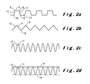
- the frame shaped structure may for example take the shape of a zig-zag member shown in figure 2b or the shape shown in figure 2c or 2d , or for example a ladder of which the rungs extend in height direction of the floor element.
- two or more of these structures may be combined into one floor element or may be combined to form the lifting means.
- connection positions 8, 18 respectively correspond to the position where an upward and downward extending bar meet each other and where a downward and upward extending bar meet each other.
- the top connection positions 8 may be interconnected by means of an upper longitudinal connecting member 9 which extends in longitudinal direction of the two-dimensional structure as is shown in figure 2d .
- the lower connection positions 18 may be interconnected by means of a lower longitudinal connecting member 19 which extends in longitudinal direction of the two-dimensional structure.
- a frame shaped structure is a two-dimensional spring and a lattice girder, the latter being preferred as it is readily commercially available and may be cut at the desired length in a simple manner.
- the frame shaped structure comprises a lower and upper longitudinal connecting member 9, 19 which extend in longitudinal direction of the frame shaped structure and which connect successive connection positions.
- the connection positions will usually take the form of a truss structure.
- a lattice girder comprising one single connecting piece connecting the connection positions in a lower part of the structure, may be used as well.
- Further suitable examples of lifting means are shown in figure 2a, 2b, 2c and 2d .
- the frame shaped structure may be a spring that extends in longitudinal direction of the floor element and has a certain thickness in transverse direction of the structure. In that case the structure takes a position alternating on opposite sides of the reinforcing wire, as the reinforcing wire will extend in longitudinal direction of the spring and be received therein.
- the lower reinforcing wire is preferably received between the successive upward and downward extending bars 10, 11 in the vicinity of the lower connection position 18.
- Connection of the reinforcing wire 6 in the lower region of the floor element 1 provides improved elongation at break and thus improves safety.
- the reinforcing wire 21 in the upper region of the floor element is received between the successive upward and downward extending bars 10, 11 in the vicinity of the upper connection position 8 and may be connected thereto.
- the lower reinforcing wire 6 and/or the upper reinforcing wire 21 are connected to the lower 18 and/or upper 8 connection positions by means of mechanical connecting members, for example a loop, clamp or wire torn around the wire and bars at the connection position.
- the frame shaped structure may be connected to the reinforcing wire 6, 21 at any other suitable position or in any other way considered suitable by the person skilled in the art.
- the connecting pieces 15 connecting the upward and downward extending bars 10, 11 are preferably positioned in such a way that they receive the reinforcing wire within or between them. This facilitates mounting of the lifting means 5.
- the lifting means may be positioned such that the reinforcing wire 6, 21 is received in the windings of the spring or the zig-zag member, whereafter the spring or the zig-zag member is moved by sliding it over the reinforcing wire 6, 21. This may probably also be done in an automatic way, so that manual manipulations are reduced to a minimum.
- the frame shaped structure contains connecting members which permit connection of the frame shaped structure to a reinforcing wire 6, present in a lower region of the floor element 1.
- connection between the frame shaped structure and the reinforcing wire may be established at the connection positions 8, 18, using the connection members 9, 19 or in any other suitable way.
- the frame shaped structure is also connected to reinforcing wires 21 present in an upper region of the floor element 1.
- the connection is preferably established with the reinforcing member positioned in the vicinity of the upright side wall 3, 13, often the reinforcing member most proximal to the upright side wall 3, 13.
- the presence of a connection permits reducing the risk to displacement of the lifting means during pouring of the concrete, to a minimum.
- the connection of the frame shaped structure to the reinforcing wire may be achieved using any technique considered suitable by the person skilled in the art.
- the frame shaped structure may be fastened to the reinforcing wire using gluing, welding, soldering or any other of such techniques.
- the connection may be achieved using mechanical connecting members, although connection may also be established by simply receiving the reinforcing wires within or between the connecting pieces 15 connecting the upward and downward extending bars 10, 11.
- the lifting means are preferably connected to the outermost reinforcing wires of the floor element, but may also be fastened to reinforcing wires shifted more to the interior of the floor element.
- Lifting of the floor element is carried out by accessing a part of the frame shaped structure from the outside of the floor element through holes 7, 17 and inserting for example a lifting hook under the upper longitudinal connecting member 9 or a connection position 8.
Abstract
Description
- The present invention relates to a floor element which is reinforced by at least one reinforcing wire extending in longitudinal direction of the floor element, the floor element comprising built-in lifting means which are accessible from the outside of the floor element to permit lifting thereof, according to the preamble of the first claim.
- Nowadays in building construction it has become common use to construct the floor and/or ceiling of a building of prefabricated floor elements which are usually made of pre-tensioned, steel reinforced concrete. When constructing a floor, a plurality of such prefabricated elements are positioned with their longitudinal sides running adjacent to one another, while the transverse sides rest on the walls of the building in construction. According to a commonly used procedure, the floor elements are produced in a more or less automated production plant and transported from there to the building site where they are to be used. Floor elements are often produced using a moving formwork. Reinforcement is provided by suspending a plurality of longitudinally extending steel wires at a position which corresponds to a lower and upper region of the floor element. The moving formwork is displaced in longitudinal direction of the wires and incorporates a concrete pouring device which pours liquid concrete to embed the wires and form the floor element. To achieve a uniform distribution of the concrete over the element, the concrete is subjected to vibration.
- To permit lifting of the floor element during transport or positioning, lifting tools are incorporated therein.
EP-A-1.344.877 discloses a floor element in which lifting hooks are mounted after the production of the floor element has been finished. According toEP-A-1.344.877 , shortly after forming of the floor element, holes are made in one of the sides of the partially hardened concrete, often the top side, in the vicinity of the angled edges. The holes extend into the interior of the floor element, towards the hollow channels. Concrete like filling material is injected through the hole, down to the hollow channel and a lifting hook is embedded in the concrete-like filling material before it is fully hardened. The load bearing capacity of such an element however strongly depends on the quality of the filling material used to embed the lifting hook.EP-A-1.344.877 does not disclose the presence of additional safety provisions to withhold the floor element in case the lifting hook or the filling material breaks and the lifting hook is pulled out of the floor element. As a consequence with the floor elements ofEP-A-1.344.877 , safety is insufficiently guaranteed. -
BE1016424A6 - Nowadays, the safety criteria to be met by the lifting tools in terms of strength and safety have become more severe. For example, in some countries it is required that the lifting means are fastened to the pre-constrained steel wires present in pre-constrained concrete.
- From
US-A-5.242.249 a pre-cast panel with built-in lifting means is known, which comprises a top and bottom layer made of concrete material, which are spaced from each other by an intermediate layer of an insulating material. The built-in lifting means comprise an apertured body having a pair of spaced apart legs attached thereto. The aperture is accessible from a top side of the panel and is adapted for connection to a lifting device, by means of a dedicated connection tool. The spaced apart legs are joined to form a U-shaped portion which is curved to form a hook. The hook is provided to engage the junction point of a truss structure provided in a bottom region of the panel. The truss structure forms part of a truss structure of a lattice girder which extends in longitudinal direction of the pre-cast panel. The lattice girder comprises an upper and lower longitudinally extending bar, which are connected to each other by diagonally extending connecting bars. However, the built-in lifting means are only suitable for use with dedicated connection tools capable of co-operating with the built-in lifting means on the one hand and the lifting device on the other hand. Usually such connection tools are not available at the building site and need to be purchased. -
EP-A-339.018 EP-A-339.018 -
EP-A-825.307 -
DE3640985 discloses a floor element which comprises a lower concrete panel provided with steel reinforcement, which may consist of a steel mat or braiding. On top of the reinforcement, a plurality of parallel, spaced-apart lattice girders is mounted. The lattice girders extend in three dimensions and function as a connecting reinforcement for further concrete which is to be poured in-situ when positioning the panel.DE3640985 does however not disclose a pre-fabricated floor element with built-in lattice girders for use as a lifting tool. - There is thus a need to a floor element with lifting means which are built-in when producing the floor element using the conventional techniques and devices used for the production of pre-fabricated concrete floor elements, whereby the lifting means do not require the use of dedicated lifting tools.
- This is achieved according to the present invention with the technical features of the characterizing part of the first claim.
- Thereto, the floor element of this invention is characterized in that
- the lifting means comprise at least one frame shaped structure with consecutive frame members running in height and longitudinal direction of the floor element, wherein the at least one frame shaped structure is extended in longitudinal direction of the floor element,
- wherein the at least one frame shaped structure contains connecting means for connection to the at least one reinforcing wire.
- An analysis of the automated production process of floor elements has revealed that the incorporation of lifting means which extend in the longitudinal and height direction of the floor element may be carried out in the course of the automated production process. This way optimum compacting of the concrete phase into which the lifting tool is incorporated may be guaranteed. The lifting tool of the present invention is particularly suitable for use with hollow floor elements, which usually comprise an upper and a lower concrete plate connected to each other by a plurality of walls which separate adjacent hollow channels from one another. As these walls have a limited thickness in transverse direction of the floor element, only those lifting means having limited dimensions in transverse direction of the floor element are suitable for incorporation therein. The lifting means used in the floor element of this invention meets this criterion as it extends mainly in two directions, i.e. the longitudinal and height direction of the floor element.
- The presence of lifting means which extend in longitudinal and height direction and which are extended in the longitudinal direction of the floor element, has the effect that additional reinforcement is provided in a direction perpendicular to the direction in which bending of the floor element usually occurs. This permits reducing the thickness of the floor element, without giving in on strength and supportive properties and without adversely affecting the bending resistance. Lifting means which are extended in the longitudinal direction provide a larger structure within which any local loads occurring during lifting, may be absorbed and neutralized within a larger part of the floor element. The larger structure has an extended contact surface area with the concrete phase of the floor element and ensures that any forces or strains occurring within the lifting means during lifting may be transferred to and absorbed within a large part of the floor element. The connection of the connecting members present in the frame shaped structure to the at least one reinforcing wire permits a direct transfer to and improved absorption of any stresses occurring in the lifting means in the full length of the reinforcing wire. As a result, the risk to wearing or breaking of the reinforcing wires following lifting is reduced. Besides that an improved stretch at breaking of the floor element is provided and the risk to the occurrence of shear forces in transverse direction of the floor element is reduced.
- The at least one frame shaped structure is preferably attached to a lower reinforcing wire in a lower part of the floor element proximal to a longitudinal upright side of the floor element, but it may also be attached to an upper reinforcing wire in an upper part of the floor element proximal to a longitudinal upright side of the floor element.
- Connecting of the two dimensional structure to the reinforcing wires is facilitated in case the frame shaped structure comprises a zig-zag member, more preferably a spring. Connection of the zig-zag member to the reinforcing wires may be achieved by inserting the reinforcing wire in the zig-zag member and by sliding it over the reinforcing wire in the longitudinal direction of the floor element. It is further preferred to receive a reinforcing wire in a lower part of the spring and more preferably also in an upper part of the spring or in other words to connect the lifting means to a reinforcing wire in a lower and preferably also in an upper part of the floor element. The present invention permits achieving optimum densification of the concrete phase which extends between the components of the zig-zag member.
- Further preferred embodiments of the floor element of this invention are defined in the dependent claims.
- The invention is further elucidated in the appending figures and
-
-
Figure 1 shows a view to a floor element of the present invention with part of it showing the interior of the floor element. -
Figure 2a, 2b and 2c show three preferred embodiments of the frame shaped lifting means. -
Figure 2d shows lower and upper longitudinal connecting members interconnecting respectively lower and upper connection positions of the frame shaped lifting means. - As can be seen from
figure 1 , the floor element of the present invention 1 is a beam shaped element having atop face 2, abottom face 12, opposite uprightlongitudinal sides transverse sides wire wires 6 in a lower part of the floor element, i.e. the part of the floor element located in the vicinity of a lower part of the channels 16 or below the channels 16. The person skilled in the art will be capable of adapting the number of reinforcing wires taking into account the envisaged application and expected load to be borne by the floor element. The floor element preferably also comprises one or a plurality of upper reinforcingwires 21 in the upper part of the floor element, i.e. the part of the floor element above the channels or in the vicinity of an upper part of the channels. In the upper part of the floor element often two or four upper reinforcingwires 21 will be present, two adjacent upper wires on each transverse side of the floor element as is shown infigure 1 . Usually the reinforcingwires - To permit lifting of the floor element, lifting means 5 are built into the floor element which are accessible from outside the floor element. Access may be provided by means of
holes holes figure 1 . Preferably access to the lifting means 5 is provided at a position on the longitudinal edge, and extends in the top face and upright longitudinal side of the floor element. Theholes longitudinal sides top face 2, but they preferably extend into both the uprightlongitudinal sides top face 2 as is shown infigure 1 . The holes may be re-filled with a concrete or cement material that may be easily removed when required to get access to the lifting means. In stead of filling the holes with concrete, one may choose to mount one or more caps to an upper or side part of the frame shaped structure, which cover the hole giving access to the lifting means. By removably mounting the caps, access to the frame shaped structure and thus the lifting tool may be achieved by a simple removal of the cap. The caps may take any form considered suitable by the person skilled in the art. - The floor element of this invention comprises built-in lifting means 5, which permit lifting of the floor element. The lifting means comprise at least one frame shaped structure with frame elements which run both in height and longitudinal direction of the floor element. As can be seen from
figure 1 , the frame shaped structure is extended in longitudinal direction of the floor element 1. The frame shaped structure 5 may extend along part of or along the whole length of the upright longitudinal side of the floor element 1. This reduces the uncertainty in relation to the position of the lifting means 5 in longitudinal direction of the floor element 1, and permits accessing the lifting means 5 at a plurality of positions in longitudinal direction. This extended shape has particular advantages in the production process of the floor elements. Usually, pre-tensioned concrete elements are produced in long lengths, which afterwards are cut to floor elements in the desired length, depending on the envisaged span. The extended shape of the frame shaped structure provides a greater versatility as to the position where the concrete elements may be cut without losing accessibility to the lifting means. - The lifting means are preferably positioned in the vicinity of an upright
longitudinal side upright side - The frame shaped structure may extend under an angle with respect to the upright
longitudinal sides longitudinal sides - According to a first preferred embodiment, the frame shaped structure 5 used as a lifting tool for the floor element of this invention, consists of a structure which mainly extends in two-dimensions, in height and longitudinal direction of the floor element 1. Such lifting means 5, which mainly extend in two directions, are particularly suitable for use with the automated production processes that are nowadays used for the production of floor elements.
- The frame shaped structure 5 which extends in height and longitudinal direction of the floor element 1 and is extended in longitudinal direction of the floor element, may be any structure considered suitable by the person skilled in the art. In a preferred embodiment, the frame shaped structure comprises a plurality of successive upward 10 and downward 11 extending bars connected to each other by means of connecting
pieces 15. The frame shaped structure may for example take the shape of a zig-zag member shown infigure 2b or the shape shown infigure 2c or 2d , or for example a ladder of which the rungs extend in height direction of the floor element. However, if so desired two or more of these structures may be combined into one floor element or may be combined to form the lifting means. - The successive upward and downward extending
bars connection position top connection positions 8 may be interconnected by means of an upper longitudinal connectingmember 9 which extends in longitudinal direction of the two-dimensional structure as is shown infigure 2d . In stead thereof or in addition thereto, the lower connection positions 18 may be interconnected by means of a lower longitudinal connectingmember 19 which extends in longitudinal direction of the two-dimensional structure. Other suitable examples of a frame shaped structure are a two-dimensional spring and a lattice girder, the latter being preferred as it is readily commercially available and may be cut at the desired length in a simple manner. In the case of a lattice girder, the frame shaped structure comprises a lower and upper longitudinal connectingmember figure 2a, 2b, 2c and 2d . - According to a second preferred embodiment, the frame shaped structure may be a spring that extends in longitudinal direction of the floor element and has a certain thickness in transverse direction of the structure. In that case the structure takes a position alternating on opposite sides of the reinforcing wire, as the reinforcing wire will extend in longitudinal direction of the spring and be received therein.
- The lower reinforcing wire is preferably received between the successive upward and downward extending
bars lower connection position 18. Connection of the reinforcingwire 6 in the lower region of the floor element 1 provides improved elongation at break and thus improves safety. Preferably also the reinforcingwire 21 in the upper region of the floor element is received between the successive upward and downward extendingbars upper connection position 8 and may be connected thereto. According to another embodiment, the lower reinforcingwire 6 and/or the upper reinforcingwire 21 are connected to the lower 18 and/or upper 8 connection positions by means of mechanical connecting members, for example a loop, clamp or wire torn around the wire and bars at the connection position. However the frame shaped structure may be connected to the reinforcingwire - The connecting
pieces 15 connecting the upward and downward extendingbars wire wire wire 6, present in a lower region of the floor element 1. Connection between the frame shaped structure and the reinforcing wire may be established at the connection positions 8, 18, using theconnection members wires 21 present in an upper region of the floor element 1. The connection is preferably established with the reinforcing member positioned in the vicinity of theupright side wall upright side wall pieces 15 connecting the upward and downward extendingbars - The lifting means are preferably connected to the outermost reinforcing wires of the floor element, but may also be fastened to reinforcing wires shifted more to the interior of the floor element.
- Lifting of the floor element is carried out by accessing a part of the frame shaped structure from the outside of the floor element through
holes member 9 or aconnection position 8.
Claims (15)
- A floor element which is reinforced by at least one reinforcing wire extending in longitudinal direction of the floor element, the floor element comprising a first and a second upright longitudinal side and built-in lifting means which are accessible from outside of the floor element to permit lifting thereof, characterized in that the lifting means comprise at least one frame shaped structure with consecutive frame elements running in height and longitudinal direction of the floor element, wherein the at least one frame shaped structure is extended in longitudinal direction of the floor element, and in that the at least one frame shaped structure contains connecting members for connection to the at least one reinforcing wire.
- A floor element as claimed in claim 1, characterized in that the at least one frame shaped structure is positioned in the vicinity of the first and/or second upright longitudinal side of the floor element.
- A floor element as claimed in anyone of claims 1-2, characterized in that the at least one frame shaped structure runs parallel to the upright longitudinal side of the floor element.
- A floor element as claimed in anyone of claims 1-3, characterized in that the at least one frame shaped structure is connected to a lower reinforcing wire in a lower part of the floor element proximal to the upright longitudinal side of the floor element.
- A floor element as claimed in anyone of claims 1-4, characterized in that the at least one frame shaped structure is connected to an upper reinforcing wire in an upper part of the floor element proximal to the upright longitudinal side of the floor element.
- A floor element as claimed in anyone of claims 1-5, characterized in that the consecutive frame members of the at least one frame shaped structure are connected to each other at connection positions, by means of connecting pieces, wherein the connection positions comprise upper connection positions in the vicinity of upper parts of the consecutive frame members and lower connection positions in the vicinity of lower parts of the consecutive frame members.
- A floor element as claimed in claim 6, characterized in that the at least one frame shaped structure comprises a lower longitudinal connecting member which extends in longitudinal direction of the floor element and which connects the lower connection positions of the consecutive frame members of the at least one frame shaped structure, and an upper longitudinal connecting member which extends in longitudinal direction of the floor element and which connects the upper connection positions of the consecutive frame members of the at least one frame shaped structure, the lower and upper longitudinal connecting member being adapted for connection to respectively a lower reinforcing wire in a lower part of the floor element and an upper reinforcing wire in an upper part of the floor element.
- A floor element as claimed in any one of claims 6-7, characterized in that a lower reinforcing wire in a lower part of the floor element is received between the consecutive frame members extending in upward and downward direction of the floor element in the vicinity of the lower connection positions.
- A floor element as claimed in any one of claims 6-8, characterized in that an upper reinforcing wire in an upper part of the floor element is received between the consecutive frame members extending in upward and downward direction of the floor element in the vicinity of the upper connection positions.
- A floor element as claimed in any one of claims 6-9, characterized in that the consecutive frame members of the at least one frame shaped structure form a zig-zag member.
- A floor element as claimed in any one of claims 6-9, characterized in that the consecutive frame members of the at least one frame shaped structure form a spring which has a limited thickness in transverse direction of the floor element.
- A floor element as claimed in any one of claims 6-11, characterized in that a lower reinforcing wire in a lower part of the floor element is connected to the consecutive frame members in the vicinity of the lower connection positions.
- A floor element as claimed in any one of claims 6-12, characterized in that an upper reinforcing wire in an upper part of the floor element is connected to the consecutive frame members in the vicinity of the upper connection positions.
- A floor element as claimed in any one of claims 1-13, characterized in that the floor element is made of pre-tensioned concrete.
- A floor element as claimed in any one of claims 1-14, characterized in that the floor element is made of armed concrete.
Priority Applications (2)
| Application Number | Priority Date | Filing Date | Title |
|---|---|---|---|
| AT07116568T ATE524627T1 (en) | 2007-09-17 | 2007-09-17 | FLOOR ELEMENT WITH LIFTING TOOLS |
| EP07116568A EP2037058B1 (en) | 2007-09-17 | 2007-09-17 | Floor element with lifting tools |
Applications Claiming Priority (1)
| Application Number | Priority Date | Filing Date | Title |
|---|---|---|---|
| EP07116568A EP2037058B1 (en) | 2007-09-17 | 2007-09-17 | Floor element with lifting tools |
Publications (2)
| Publication Number | Publication Date |
|---|---|
| EP2037058A1 true EP2037058A1 (en) | 2009-03-18 |
| EP2037058B1 EP2037058B1 (en) | 2011-09-14 |
Family
ID=38950826
Family Applications (1)
| Application Number | Title | Priority Date | Filing Date |
|---|---|---|---|
| EP07116568A Not-in-force EP2037058B1 (en) | 2007-09-17 | 2007-09-17 | Floor element with lifting tools |
Country Status (2)
| Country | Link |
|---|---|
| EP (1) | EP2037058B1 (en) |
| AT (1) | ATE524627T1 (en) |
Cited By (2)
| Publication number | Priority date | Publication date | Assignee | Title |
|---|---|---|---|---|
| NO341267B1 (en) * | 2014-08-04 | 2017-10-02 | Svein Berg Holding As | Building element, building comprising one or more building elements and method for joining building elements and supporting elements |
| RU199196U1 (en) * | 2019-12-12 | 2020-08-21 | Акционерное общество "Завод ЖБК-1" | MULTI-CAPACITY PRE-STRESSED CERAMZITE CONCRETE OVERLAPPING PLATE WITH INCREASED ANCHORING OF THE VALVES |
Families Citing this family (1)
| Publication number | Priority date | Publication date | Assignee | Title |
|---|---|---|---|---|
| CN105971175A (en) * | 2016-05-17 | 2016-09-28 | 张宗楼 | Hollow laminated floor slab |
Citations (7)
| Publication number | Priority date | Publication date | Assignee | Title |
|---|---|---|---|---|
| US2794336A (en) * | 1953-06-25 | 1957-06-04 | Superior Concrete Accessories | Lag screw anchoring insert for a concrete slab |
| GB2128654A (en) * | 1982-10-12 | 1984-05-02 | Balfour Beatty Ltd | Wall panel |
| FR2543481A1 (en) * | 1983-03-31 | 1984-10-05 | Francis Laroche | Device for anchoring in concrete |
| US5058345A (en) * | 1990-07-17 | 1991-10-22 | Martinez Manuel J | Reinforced structural panel and method of making same |
| US5242249A (en) * | 1991-08-12 | 1993-09-07 | Mmi Products | Pre-cast panel lifting insert |
| DE29913638U1 (en) * | 1999-07-30 | 2000-02-03 | Jelonnek Guenther | Building construction |
| BE1016424A6 (en) * | 2005-01-24 | 2006-10-03 | Echo | Lifting hook for prefabricated reinforced concrete slab, comprises U shaped loop section and cross direction part for positioning beneath slab reinforcing structure |
-
2007
- 2007-09-17 AT AT07116568T patent/ATE524627T1/en not_active IP Right Cessation
- 2007-09-17 EP EP07116568A patent/EP2037058B1/en not_active Not-in-force
Patent Citations (7)
| Publication number | Priority date | Publication date | Assignee | Title |
|---|---|---|---|---|
| US2794336A (en) * | 1953-06-25 | 1957-06-04 | Superior Concrete Accessories | Lag screw anchoring insert for a concrete slab |
| GB2128654A (en) * | 1982-10-12 | 1984-05-02 | Balfour Beatty Ltd | Wall panel |
| FR2543481A1 (en) * | 1983-03-31 | 1984-10-05 | Francis Laroche | Device for anchoring in concrete |
| US5058345A (en) * | 1990-07-17 | 1991-10-22 | Martinez Manuel J | Reinforced structural panel and method of making same |
| US5242249A (en) * | 1991-08-12 | 1993-09-07 | Mmi Products | Pre-cast panel lifting insert |
| DE29913638U1 (en) * | 1999-07-30 | 2000-02-03 | Jelonnek Guenther | Building construction |
| BE1016424A6 (en) * | 2005-01-24 | 2006-10-03 | Echo | Lifting hook for prefabricated reinforced concrete slab, comprises U shaped loop section and cross direction part for positioning beneath slab reinforcing structure |
Cited By (3)
| Publication number | Priority date | Publication date | Assignee | Title |
|---|---|---|---|---|
| NO341267B1 (en) * | 2014-08-04 | 2017-10-02 | Svein Berg Holding As | Building element, building comprising one or more building elements and method for joining building elements and supporting elements |
| US10081942B2 (en) | 2014-08-04 | 2018-09-25 | Svein Berg Holding As | Building element, a building comprising one or more such building elements and a method for joining such a building element and a support element |
| RU199196U1 (en) * | 2019-12-12 | 2020-08-21 | Акционерное общество "Завод ЖБК-1" | MULTI-CAPACITY PRE-STRESSED CERAMZITE CONCRETE OVERLAPPING PLATE WITH INCREASED ANCHORING OF THE VALVES |
Also Published As
| Publication number | Publication date |
|---|---|
| ATE524627T1 (en) | 2011-09-15 |
| EP2037058B1 (en) | 2011-09-14 |
Similar Documents
| Publication | Publication Date | Title |
|---|---|---|
| KR101870930B1 (en) | Method and device for strengthening and lightening floor and roof framing | |
| KR100742577B1 (en) | Composite structural framing system | |
| KR101018824B1 (en) | Composite beam making method using t-typed channel beam and structure construction method thereof | |
| EP2181224A1 (en) | Improved girders for reinforcing concrete and method for connecting them to pillars in order to provide continuity from bay to bay | |
| EP2037058B1 (en) | Floor element with lifting tools | |
| KR100698608B1 (en) | Doubly prestressed roof-ceiling construction with grid flat-soffit for extremely large spans | |
| CN110392758B (en) | Inverted T-shaped section mixed prestressed concrete beam and panel construction method using same | |
| KR100911148B1 (en) | Lightened Coping for bridge | |
| EP0061483A1 (en) | Box beam reinforced concrete structure | |
| KR101631096B1 (en) | Multiple composite girder for bridge | |
| KR101581320B1 (en) | Precast coping structure for bridge using precast deck | |
| JP5866038B1 (en) | Deck plate, floor slab, deck plate manufacturing method, and floor slab construction method | |
| KR101357280B1 (en) | Pc column for constructing multi story simultaneously and pc integrating method using this pc column | |
| KR101212259B1 (en) | Composite slab using corrugated plate and making method therewith | |
| KR101698807B1 (en) | Manufacturing method of the psc girder using the corrugated steel plate and the psc girder manufactured thereby | |
| EP1416101A1 (en) | Composite beam | |
| JP7264690B2 (en) | METHOD FOR MANUFACTURING CONCRETE WALL STRUCTURE AND BUILDING STRUCTURE | |
| JP2754369B2 (en) | Rebar unit for void slab of building structure | |
| CN112359965A (en) | Precast concrete assembled structure with rib mold structure and construction method thereof | |
| KR200345789Y1 (en) | Steel prestressed concrete grider utilizing a steel pipe as a mold | |
| KR101708274B1 (en) | Integrated hollow bodies for void slab, void slim-floor and flat slab structure using the same | |
| WO2012072671A1 (en) | A composite beam flooring system | |
| CN112942679B (en) | Precast concrete frame beam capable of realizing standardization and construction method thereof | |
| JP6114600B2 (en) | Reinforced concrete structure | |
| CN215167033U (en) | Board end exempts from to go out muscle superimposed sheet and connected node thereof |
Legal Events
| Date | Code | Title | Description |
|---|---|---|---|
| PUAI | Public reference made under article 153(3) epc to a published international application that has entered the european phase |
Free format text: ORIGINAL CODE: 0009012 |
|
| AK | Designated contracting states |
Kind code of ref document: A1 Designated state(s): AT BE BG CH CY CZ DE DK EE ES FI FR GB GR HU IE IS IT LI LT LU LV MC MT NL PL PT RO SE SI SK TR |
|
| AX | Request for extension of the european patent |
Extension state: AL BA HR MK RS |
|
| 17P | Request for examination filed |
Effective date: 20090821 |
|
| 17Q | First examination report despatched |
Effective date: 20090921 |
|
| AKX | Designation fees paid |
Designated state(s): AT BE BG CH CY CZ DE DK EE ES FI FR GB GR HU IE IS IT LI LT LU LV MC MT NL PL PT RO SE SI SK TR |
|
| GRAP | Despatch of communication of intention to grant a patent |
Free format text: ORIGINAL CODE: EPIDOSNIGR1 |
|
| GRAS | Grant fee paid |
Free format text: ORIGINAL CODE: EPIDOSNIGR3 |
|
| GRAA | (expected) grant |
Free format text: ORIGINAL CODE: 0009210 |
|
| AK | Designated contracting states |
Kind code of ref document: B1 Designated state(s): AT BE BG CH CY CZ DE DK EE ES FI FR GB GR HU IE IS IT LI LT LU LV MC MT NL PL PT RO SE SI SK TR |
|
| REG | Reference to a national code |
Ref country code: GB Ref legal event code: FG4D |
|
| REG | Reference to a national code |
Ref country code: CH Ref legal event code: EP |
|
| REG | Reference to a national code |
Ref country code: IE Ref legal event code: FG4D |
|
| REG | Reference to a national code |
Ref country code: DE Ref legal event code: R096 Ref document number: 602007017137 Country of ref document: DE Effective date: 20111110 |
|
| REG | Reference to a national code |
Ref country code: NL Ref legal event code: T3 |
|
| PG25 | Lapsed in a contracting state [announced via postgrant information from national office to epo] |
Ref country code: LT Free format text: LAPSE BECAUSE OF FAILURE TO SUBMIT A TRANSLATION OF THE DESCRIPTION OR TO PAY THE FEE WITHIN THE PRESCRIBED TIME-LIMIT Effective date: 20110914 Ref country code: SE Free format text: LAPSE BECAUSE OF FAILURE TO SUBMIT A TRANSLATION OF THE DESCRIPTION OR TO PAY THE FEE WITHIN THE PRESCRIBED TIME-LIMIT Effective date: 20110914 Ref country code: FI Free format text: LAPSE BECAUSE OF FAILURE TO SUBMIT A TRANSLATION OF THE DESCRIPTION OR TO PAY THE FEE WITHIN THE PRESCRIBED TIME-LIMIT Effective date: 20110914 |
|
| PGFP | Annual fee paid to national office [announced via postgrant information from national office to epo] |
Ref country code: FR Payment date: 20111229 Year of fee payment: 5 Ref country code: NL Payment date: 20111228 Year of fee payment: 5 |
|
| LTIE | Lt: invalidation of european patent or patent extension |
Effective date: 20110914 |
|
| PG25 | Lapsed in a contracting state [announced via postgrant information from national office to epo] |
Ref country code: GR Free format text: LAPSE BECAUSE OF FAILURE TO SUBMIT A TRANSLATION OF THE DESCRIPTION OR TO PAY THE FEE WITHIN THE PRESCRIBED TIME-LIMIT Effective date: 20111215 Ref country code: CY Free format text: LAPSE BECAUSE OF FAILURE TO SUBMIT A TRANSLATION OF THE DESCRIPTION OR TO PAY THE FEE WITHIN THE PRESCRIBED TIME-LIMIT Effective date: 20110914 Ref country code: AT Free format text: LAPSE BECAUSE OF FAILURE TO SUBMIT A TRANSLATION OF THE DESCRIPTION OR TO PAY THE FEE WITHIN THE PRESCRIBED TIME-LIMIT Effective date: 20110914 Ref country code: SI Free format text: LAPSE BECAUSE OF FAILURE TO SUBMIT A TRANSLATION OF THE DESCRIPTION OR TO PAY THE FEE WITHIN THE PRESCRIBED TIME-LIMIT Effective date: 20110914 Ref country code: LV Free format text: LAPSE BECAUSE OF FAILURE TO SUBMIT A TRANSLATION OF THE DESCRIPTION OR TO PAY THE FEE WITHIN THE PRESCRIBED TIME-LIMIT Effective date: 20110914 |
|
| REG | Reference to a national code |
Ref country code: AT Ref legal event code: MK05 Ref document number: 524627 Country of ref document: AT Kind code of ref document: T Effective date: 20110914 |
|
| PG25 | Lapsed in a contracting state [announced via postgrant information from national office to epo] |
Ref country code: MC Free format text: LAPSE BECAUSE OF NON-PAYMENT OF DUE FEES Effective date: 20110930 Ref country code: CZ Free format text: LAPSE BECAUSE OF FAILURE TO SUBMIT A TRANSLATION OF THE DESCRIPTION OR TO PAY THE FEE WITHIN THE PRESCRIBED TIME-LIMIT Effective date: 20110914 Ref country code: IS Free format text: LAPSE BECAUSE OF FAILURE TO SUBMIT A TRANSLATION OF THE DESCRIPTION OR TO PAY THE FEE WITHIN THE PRESCRIBED TIME-LIMIT Effective date: 20120114 Ref country code: SK Free format text: LAPSE BECAUSE OF FAILURE TO SUBMIT A TRANSLATION OF THE DESCRIPTION OR TO PAY THE FEE WITHIN THE PRESCRIBED TIME-LIMIT Effective date: 20110914 |
|
| REG | Reference to a national code |
Ref country code: CH Ref legal event code: PL |
|
| PG25 | Lapsed in a contracting state [announced via postgrant information from national office to epo] |
Ref country code: PL Free format text: LAPSE BECAUSE OF FAILURE TO SUBMIT A TRANSLATION OF THE DESCRIPTION OR TO PAY THE FEE WITHIN THE PRESCRIBED TIME-LIMIT Effective date: 20110914 Ref country code: PT Free format text: LAPSE BECAUSE OF FAILURE TO SUBMIT A TRANSLATION OF THE DESCRIPTION OR TO PAY THE FEE WITHIN THE PRESCRIBED TIME-LIMIT Effective date: 20120116 Ref country code: RO Free format text: LAPSE BECAUSE OF FAILURE TO SUBMIT A TRANSLATION OF THE DESCRIPTION OR TO PAY THE FEE WITHIN THE PRESCRIBED TIME-LIMIT Effective date: 20110914 Ref country code: EE Free format text: LAPSE BECAUSE OF FAILURE TO SUBMIT A TRANSLATION OF THE DESCRIPTION OR TO PAY THE FEE WITHIN THE PRESCRIBED TIME-LIMIT Effective date: 20110914 Ref country code: IT Free format text: LAPSE BECAUSE OF FAILURE TO SUBMIT A TRANSLATION OF THE DESCRIPTION OR TO PAY THE FEE WITHIN THE PRESCRIBED TIME-LIMIT Effective date: 20110914 |
|
| PGFP | Annual fee paid to national office [announced via postgrant information from national office to epo] |
Ref country code: DE Payment date: 20120215 Year of fee payment: 5 |
|
| REG | Reference to a national code |
Ref country code: IE Ref legal event code: MM4A |
|
| PGFP | Annual fee paid to national office [announced via postgrant information from national office to epo] |
Ref country code: BE Payment date: 20120123 Year of fee payment: 5 |
|
| PLBE | No opposition filed within time limit |
Free format text: ORIGINAL CODE: 0009261 |
|
| STAA | Information on the status of an ep patent application or granted ep patent |
Free format text: STATUS: NO OPPOSITION FILED WITHIN TIME LIMIT |
|
| PG25 | Lapsed in a contracting state [announced via postgrant information from national office to epo] |
Ref country code: LI Free format text: LAPSE BECAUSE OF NON-PAYMENT OF DUE FEES Effective date: 20110930 Ref country code: CH Free format text: LAPSE BECAUSE OF NON-PAYMENT OF DUE FEES Effective date: 20110930 Ref country code: DK Free format text: LAPSE BECAUSE OF FAILURE TO SUBMIT A TRANSLATION OF THE DESCRIPTION OR TO PAY THE FEE WITHIN THE PRESCRIBED TIME-LIMIT Effective date: 20110914 Ref country code: IE Free format text: LAPSE BECAUSE OF NON-PAYMENT OF DUE FEES Effective date: 20110917 |
|
| 26N | No opposition filed |
Effective date: 20120615 |
|
| REG | Reference to a national code |
Ref country code: DE Ref legal event code: R097 Ref document number: 602007017137 Country of ref document: DE Effective date: 20120615 |
|
| PG25 | Lapsed in a contracting state [announced via postgrant information from national office to epo] |
Ref country code: MT Free format text: LAPSE BECAUSE OF FAILURE TO SUBMIT A TRANSLATION OF THE DESCRIPTION OR TO PAY THE FEE WITHIN THE PRESCRIBED TIME-LIMIT Effective date: 20110914 |
|
| BERE | Be: lapsed |
Owner name: ECHO Effective date: 20120930 |
|
| REG | Reference to a national code |
Ref country code: NL Ref legal event code: V1 Effective date: 20130401 |
|
| PG25 | Lapsed in a contracting state [announced via postgrant information from national office to epo] |
Ref country code: ES Free format text: LAPSE BECAUSE OF FAILURE TO SUBMIT A TRANSLATION OF THE DESCRIPTION OR TO PAY THE FEE WITHIN THE PRESCRIBED TIME-LIMIT Effective date: 20111225 |
|
| GBPC | Gb: european patent ceased through non-payment of renewal fee |
Effective date: 20120917 |
|
| PG25 | Lapsed in a contracting state [announced via postgrant information from national office to epo] |
Ref country code: BG Free format text: LAPSE BECAUSE OF FAILURE TO SUBMIT A TRANSLATION OF THE DESCRIPTION OR TO PAY THE FEE WITHIN THE PRESCRIBED TIME-LIMIT Effective date: 20111214 |
|
| REG | Reference to a national code |
Ref country code: FR Ref legal event code: ST Effective date: 20130531 |
|
| PG25 | Lapsed in a contracting state [announced via postgrant information from national office to epo] |
Ref country code: BE Free format text: LAPSE BECAUSE OF NON-PAYMENT OF DUE FEES Effective date: 20120930 Ref country code: DE Free format text: LAPSE BECAUSE OF NON-PAYMENT OF DUE FEES Effective date: 20130403 Ref country code: GB Free format text: LAPSE BECAUSE OF NON-PAYMENT OF DUE FEES Effective date: 20120917 |
|
| REG | Reference to a national code |
Ref country code: DE Ref legal event code: R119 Ref document number: 602007017137 Country of ref document: DE Effective date: 20130403 |
|
| PG25 | Lapsed in a contracting state [announced via postgrant information from national office to epo] |
Ref country code: FR Free format text: LAPSE BECAUSE OF NON-PAYMENT OF DUE FEES Effective date: 20121001 Ref country code: NL Free format text: LAPSE BECAUSE OF NON-PAYMENT OF DUE FEES Effective date: 20130401 |
|
| PG25 | Lapsed in a contracting state [announced via postgrant information from national office to epo] |
Ref country code: TR Free format text: LAPSE BECAUSE OF FAILURE TO SUBMIT A TRANSLATION OF THE DESCRIPTION OR TO PAY THE FEE WITHIN THE PRESCRIBED TIME-LIMIT Effective date: 20110914 |
|
| PG25 | Lapsed in a contracting state [announced via postgrant information from national office to epo] |
Ref country code: HU Free format text: LAPSE BECAUSE OF FAILURE TO SUBMIT A TRANSLATION OF THE DESCRIPTION OR TO PAY THE FEE WITHIN THE PRESCRIBED TIME-LIMIT Effective date: 20110914 |
|
| PG25 | Lapsed in a contracting state [announced via postgrant information from national office to epo] |
Ref country code: LU Free format text: LAPSE BECAUSE OF NON-PAYMENT OF DUE FEES Effective date: 20120917 |