EP2036636B1 - Werkzeugaufnahmekopf für eine Drehmaschine - Google Patents
Werkzeugaufnahmekopf für eine Drehmaschine Download PDFInfo
- Publication number
- EP2036636B1 EP2036636B1 EP20080016039 EP08016039A EP2036636B1 EP 2036636 B1 EP2036636 B1 EP 2036636B1 EP 20080016039 EP20080016039 EP 20080016039 EP 08016039 A EP08016039 A EP 08016039A EP 2036636 B1 EP2036636 B1 EP 2036636B1
- Authority
- EP
- European Patent Office
- Prior art keywords
- tool
- holding head
- axis
- head according
- quick
- Prior art date
- Legal status (The legal status is an assumption and is not a legal conclusion. Google has not performed a legal analysis and makes no representation as to the accuracy of the status listed.)
- Not-in-force
Links
- 238000005553 drilling Methods 0.000 claims description 21
- 238000003754 machining Methods 0.000 description 5
- 238000003801 milling Methods 0.000 description 3
- 230000008878 coupling Effects 0.000 description 1
- 238000010168 coupling process Methods 0.000 description 1
- 238000005859 coupling reaction Methods 0.000 description 1
Images


Classifications
-
- B—PERFORMING OPERATIONS; TRANSPORTING
- B23—MACHINE TOOLS; METAL-WORKING NOT OTHERWISE PROVIDED FOR
- B23B—TURNING; BORING
- B23B29/00—Holders for non-rotary cutting tools; Boring bars or boring heads; Accessories for tool holders
- B23B29/24—Tool holders for a plurality of cutting tools, e.g. turrets
- B23B29/32—Turrets adjustable by power drive, i.e. turret heads
- B23B29/323—Turrets with power operated angular positioning devices
-
- B—PERFORMING OPERATIONS; TRANSPORTING
- B23—MACHINE TOOLS; METAL-WORKING NOT OTHERWISE PROVIDED FOR
- B23B—TURNING; BORING
- B23B3/00—General-purpose turning-machines or devices, e.g. centre lathes with feed rod and lead screw; Sets of turning-machines
- B23B3/16—Turret lathes for turning individually-chucked workpieces
- B23B3/167—Turret lathes for turning individually-chucked workpieces lathe with two or more toolslides carrying turrets
- B23B3/168—Arrangements for performing other machining operations, e.g. milling, drilling
-
- B—PERFORMING OPERATIONS; TRANSPORTING
- B23—MACHINE TOOLS; METAL-WORKING NOT OTHERWISE PROVIDED FOR
- B23Q—DETAILS, COMPONENTS, OR ACCESSORIES FOR MACHINE TOOLS, e.g. ARRANGEMENTS FOR COPYING OR CONTROLLING; MACHINE TOOLS IN GENERAL CHARACTERISED BY THE CONSTRUCTION OF PARTICULAR DETAILS OR COMPONENTS; COMBINATIONS OR ASSOCIATIONS OF METAL-WORKING MACHINES, NOT DIRECTED TO A PARTICULAR RESULT
- B23Q1/00—Members which are comprised in the general build-up of a form of machine, particularly relatively large fixed members
- B23Q1/70—Stationary or movable members for carrying working-spindles for attachment of tools or work
-
- B—PERFORMING OPERATIONS; TRANSPORTING
- B23—MACHINE TOOLS; METAL-WORKING NOT OTHERWISE PROVIDED FOR
- B23Q—DETAILS, COMPONENTS, OR ACCESSORIES FOR MACHINE TOOLS, e.g. ARRANGEMENTS FOR COPYING OR CONTROLLING; MACHINE TOOLS IN GENERAL CHARACTERISED BY THE CONSTRUCTION OF PARTICULAR DETAILS OR COMPONENTS; COMBINATIONS OR ASSOCIATIONS OF METAL-WORKING MACHINES, NOT DIRECTED TO A PARTICULAR RESULT
- B23Q5/00—Driving or feeding mechanisms; Control arrangements therefor
- B23Q5/02—Driving main working members
- B23Q5/04—Driving main working members rotary shafts, e.g. working-spindles
- B23Q5/043—Accessories for spindle drives
- B23Q5/045—Angle drives
-
- B—PERFORMING OPERATIONS; TRANSPORTING
- B23—MACHINE TOOLS; METAL-WORKING NOT OTHERWISE PROVIDED FOR
- B23Q—DETAILS, COMPONENTS, OR ACCESSORIES FOR MACHINE TOOLS, e.g. ARRANGEMENTS FOR COPYING OR CONTROLLING; MACHINE TOOLS IN GENERAL CHARACTERISED BY THE CONSTRUCTION OF PARTICULAR DETAILS OR COMPONENTS; COMBINATIONS OR ASSOCIATIONS OF METAL-WORKING MACHINES, NOT DIRECTED TO A PARTICULAR RESULT
- B23Q5/00—Driving or feeding mechanisms; Control arrangements therefor
- B23Q5/02—Driving main working members
- B23Q5/04—Driving main working members rotary shafts, e.g. working-spindles
- B23Q5/20—Adjusting or stopping working-spindles in a predetermined position
Definitions
- the above invention relates to a tool receiving head for a lathe, in particular for a multi-spindle lathe.
- the known tool holder heads are slidably mounted with the aid of dovetail guides.
- tool receiving heads which receive rotating tools, e.g. Drilling or milling tools.
- Out DE-A-3702424 is a tool turret for a machine tool, in particular a lathe, known.
- a drive motor is provided with a first axis of rotation which acts on a second shaft, whose axis is arranged in a second plane and acts via a gear on a third drive shaft for driving a tool which is rotatable about an angular drive about a fourth axis.
- the object of the invention is achieved with a tool receiving head for a lathe according to claim 1.
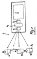
- the tool holder head 1 on a controllable motor 2 has a connector 3, a quick connector 4 and a hydraulic brake 5.
- the tool receiving head 1 is equipped with a variety of tools.
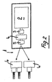
- FIG. 2 Another embodiment of the tool receiving head is in FIG. 2 also shown here, a motor 2, a connector 3, a quick connector 4 and a hydraulic brake 5 are provided which drive in this case tool groups.
- the hydraulic brake 5 When the fixed tools are in the working position, the hydraulic brake 5 is actuated in order to lock the tools in a specific working position. If, however, a number of rotating tools is provided, the brake 5 is released.
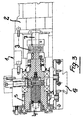
- FIG. 3 can be taken in detail in detail the drive motor 2, the drive shaft 7, a coupling piece 3 and the quick connector 4, a tool (not shown in FIG FIG. 3 ) is set in rotary motion.
- the quick connector is known in the art.
- the tool holder head 1 can be locked in any desired position.
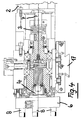
- FIG. 4 can be taken from the drive motor 2 with the associated drive shaft 7; the drive motor 2 drives via a connector 3 to the quick connector 4, which according to FIG. 4 a receptacle 6, which is equipped with numerous stationary tools 8 for performing shooting.
- the tool receiving head 1 is allowed to receive a disk-like tool holder, on which numerous fixed workpieces are arranged for performing radial and frontal machining operations.
- the motor 2 is controlled such that a precision machining of the workpiece is possible, further there is a tool change, whereby the desired machining tool is moved to the processing position.
- the presence of a hydraulic brake 5 allows locking of the turret in a secure and rigid position.
- the motor is operated to give the tool the necessary torque.
- the hydraulic brake 5 is unlocked.
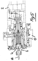
- FIG. 5 can always be the engine 2 with the associated drive shaft 7, the connector 3 and the quick connector 4 are removed.
- the receptacle (6) has a bearing, which has a drilling tool 18 which lies in axis to the motor 2.
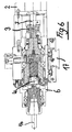
- FIG. 6 the receptacle 6 is shown and equipped with a tool 16 with a larger diameter to perform drilling or milling operations with larger chip removal.
- the tool holder head 1 has a slide 17 in dovetail guide on its underside, thereby allowing a displaceable mounting in the body of the machine tool.
- FIG. 7 shows in section part of the tool holder head, which is suitable for the implementation of a 90 ° deflected bore.
- the tool marked 18 is used to perform in the workpiece P holes in the axis.
- a plate 30 is provided, which serves to tension the drilling tool 18.
- the plate 30 is pivotable and lockable by providing oblong holes 31 arranged along a circular arc line.
- a suitable key on a gear 32 Before use of the drilling tool 18 is acted upon with the aid of a suitable key on a gear 32, thereby making it possible to the teeth 33 of the plate 30th act and thus make a positional arrangement of the drilling tool 18 relative to the workpiece.
- FIG. 9 shows that thanks to an operation on the devices 32, 33 of the plate 30 a pivoting movement about the axis Z has been carried out, whereby the drilling tool 18 was no longer pivoted in axis with the workpiece, but slightly to the left in the drawing, whereby the position of to be performed hole outside the axis of the tool piece P comes to rest.
- the pivoting movement of the plate 31 can take place both to the left and to the right about the axis Z.
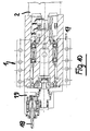
- FIG. 10 shows in section the tool holder with the drilling tool 18, which is received by the device 19 and is offset radially relative to the longitudinal axis of the device.
Landscapes
- Engineering & Computer Science (AREA)
- Mechanical Engineering (AREA)
- Cutting Tools, Boring Holders, And Turrets (AREA)
- Gripping On Spindles (AREA)
- Drilling And Boring (AREA)
Description
- Die vorstehende Erfindung betrifft einen Werkzeugaufnahmekopf für eine Drehmaschine, insbesondere für eine Mehrspindeldrehmaschine.
- Es ist bekannt, dass in Mehrspindeldrehmaschinen Werkzeugaufnahmeköpfe zum Einsatz gelangen, die feststehende Werkzeuge für die Bearbeitung des Werkstückes aufnehmen.
- Die bekannten Werkzeugaufnahmeköpfe sind verschiebbar unter Zuhilfenahme von Schwalbenschwanzführungen gelagert.
- Desweiteren sind Werkzeugaufnahmeköpfe bekannt geworden, welche sich drehende Werkzeuge aufnehmen, z.B. Bohr- oder Fräswerkzeuge.
- Die Tatsache, dass der Werkzeugaufnahmekopf feststehende sowie sich drehende Werkzeuge aufnimmt, bedingt es, zwei unterschiedliche Antriebsvorrichtungen bzw. Arretiervorrichtungen vorzusehen, was einen erheblichen Platzbedarf in der Werkzeugmaschine mit sich bringt.
- Mit Zunahme an Werkzeugaufnahmeköpfen, ergibt sich nicht nur ein erhöhter Platzbedarf für deren Montage, es ist auch ein größerer Zeitaufwand sowie der Einsatz von Fachkräften für die Montage bzw. die Demontage der unterschiedlichen Werkzeugeinheiten erforderlich.
- Diese Tatsache senkt in erheblicher Weise den Wirkungsgrad der Werkzeugmaschine.
- Aus
DE-A-3702424 ist ein Werkzeugrevolver für eine Werkzeugmaschine, insbesondere eine Drehmaschine, bekannt geworden. Dort ist ein Antriebsmotor mit einer ersten Drehachse vorgesehen, der auf eine zweite Welle einwirkt, deren Achse in einer zweiten Ebene angeordnet ist und über ein Zahnrad auf eine dritte Antriebswelle zum Antrieb eines Werkzeuges einwirkt, das über ein Winkeltrieb um eine vierte Achse drehbar ist. - Die Vorsehung mehrerer Drehachsen führt bei dieser Ausführungsform (in der Summe zu erheblichen) Lagerspielen, und zu einer Vergrößerung der Abmessungen dieser bekannten Vorrichtung. Ferner sind bei dem bekannten Werkzeugrevolver für eine Werkzeugmaschine keine Einstellvorgänge (Presetting) außerhalb der Maschine möglich.
- Es ist daher Aufgabe der vorstehenden Erfindung, die Nachteile des Standes der Technik zu vermeiden und einen Werkzeugaufnahmekopf vorzuschlagen, der auf einem bekannten Kreuzschlitten einer Werkzeugmaschine montierbar ist, insbesondere einer Mehrspindeldrehmaschine, der verminderte Abmessungen aufweist und die Möglichkeit bietet, rasch unterschiedliche Werkzeugaufnahmeköpfe zu montieren, wobei diese Werkzeugaufnahemköpfe vormontierbar und außerhalb der Maschine einstellbar sind und ferner die Montage von feststehenden Werkzeugen sowie die Montage von einem oder mehreren sich drehenden Werkzeugen ermöglicht. Desweiteren soll die Möglichkeit eröffnet werden, auf rasche Weise von einer Werkzeugart auf eine andere Werkzeugart umzurüsten, und die Möglichkeit zu schaffen, Bohrungen in Achse sowie außerachsig gegenüber dem Werkzeug anzubringen.
- Die erfindungsgemäße Aufgabe wird mit einem Werkzeugaufnahmekopf für eine Drehmaschine gemäß Anspruch 1 gelöst.
- Die erfindungsgemäße Einrichtung wird nun genauer beschrieben, unter Bezugnahme auf die beigefügten Zeichnungen.
-
-
Figur 1 in schematischer Ansicht einen ersten Werkzeugaufnahmekopf mit einer Werkzeugaufnahme; -
Figur 2 einen zweiten Werkzeugaufnahmekopf mit einer Werkzeugaufnahme; -
Figur 3 den erfindungsgemäßen Werkzeugaufnahmekopf im Längsschnitt; -
Figur 4 den Werkzeugaufnahmekopf im Längsschnitt, ausgerüstet mit einer Vielzahl von Werkzeugen; -
Figur 5 den Werkzeugaufnahmekopf ausgerüstet mit einem Bohrwerkzeug; -
Figur 6 den Werkzeugaufnahmekopf, ausgerüstet mit einem Werkzeug mit größerem Durchmesser, zum Bohren und Fräsen; -
Figur 7 den Werkzeugaufnahmekopf im Schnitt während der Durchführung eines Bohrvorganges, in Achse mit dem Werkstück; -
Figur 8 in Vorderansicht die Einrichtung für die Lageanordnung des Werkzeuges zur Durchführung einer Bohrung radial versetzt zur Längsachse des Werkstückes; -
Figur 9 schematisch in Vorderansicht die Positioniereinrichtung des Werkzeuges zur Durchführung einer radial zur Achse versetzten Bohrung; -
Figur 10 im Schnitt die Vorrichtung gemäßFigur 8 und9 . - Wie der schematischen Zeichnung gemäß
Figur 1 zu entnehmen ist, weist der Werkzeugaufnahmekopf 1 einen steuerbaren Motor 2 auf, dessen Antriebswelle ein Verbindungsstück 3, einen Schnellanschluss 4 sowie eine hydraulische Bremse 5 aufweist. Der Werkzeugaufnahmekopf 1 ist mit einer Vielzahl von Werkzeugen ausgerüstet. - Eine weitere Ausführungsform des Werkzeugaufnahmekopfes ist in
Figur 2 dargestellt, auch hier ist ein Motor 2, ein Verbindungsstück 3, ein Schnellanschluss 4 sowie eine hydraulische Bremse 5 vorgesehen, die in diesem Fall Werkzeuggruppen antreiben. - Wenn sich die fest angeordneten Werkzeuge in Arbeitsstellung befinden, erfolgt ein Betätigen der hydraulischen Bremse 5, um die Werkzeuge in einer bestimmten Arbeitsstellung zu arretieren. Ist hingegen eine Anzahl von sich drehenden Werkzeugen vorgesehen, so ist die Bremse 5 gelöst.
- Der
Figur 3 kann im Schnitt im Detail der Antriebsmotor 2 entnommen werden, dessen Antriebswelle 7, über ein Kupplungsstück 3 und den Schnellanschluss 4, ein Werkzeug (nicht dargestellt inFigur 3 ) in Drehbewegung versetzt. - Der Schnellanschluss ist aus dem Stand der Technik bekannt.
- Dank der Vorsehung einer hydraulischen Bremse 5 kann der Werkzeugaufnahmekopf 1 in jeder gewünschten Lage arretiert werden.
- Der
Figur 4 kann der Antriebsmotor 2 mit der dazugehörenden Antriebswelle 7 entnommen werden; der Antriebsmotor 2 treibt über ein Verbindungsstück 3 den Schnellanschluss 4 an, welcher gemäßFigur 4 eine Aufnahme 6 aufweist, die mit zahlreichen feststehenden Werkzeugen 8 zur Durchführung von Dreharbeiten ausgerüstet ist. - Somit wird es ermöglicht, dass der Werkzeugaufnahmekopf 1 eine scheibenartige Werkzeugaufnahme aufnimmt, auf der zahlreiche fest angeordnete Werkstücke zur Durchführung von radialen und frontalen Bearbeitungsvorgängen angeordnet sind.
- In diesem Fall wird der Motor 2 derartig angesteuert, dass eine Präzisionsbearbeitung des Werkstückes möglich wird, ferner erfolgt ein Werkzeugwechsel, wodurch das gewünschte Bearbeitungswerkzeug in Bearbeitungslage verfahren wird. Das Vorhandensein einer hydraulischen Bremse 5 erlaubt ein Arretieren des Revolverkopfes in sicherer und starrer Lage.
- In dieser Lage wird durch die Vorrichtung die Funktion eines motorisch angetriebenen Schlittens erfüllt (siehe
Figur 5 und6 ). - Für diese Funktionsweise stehen zwei Gerätearten zur Verfügung:
- die erste Geräteart ist schematisch in
Figur 5 zur Durchführung kleiner Bohrungen dargestellt; - die zweite Geräteart entspricht der Darstellung nach
Figur 6 und dient zur Durchführung von schweren Bearbeitungsvorgängen, wobei das Bohrwerkzeug über die Einrichtung 6 sowie die dazugehörenden Wälzlager aufgenommen wird. - In diesem Fall wird der Motor betätigt, um dem Werkzeug die notwendige Drehkraft zu vermitteln. Die hydraulische Bremse 5 ist entriegelt.
- Der
Figur 5 kann stets der Motor 2 mit der dazugehörigen Antriebswelle 7, dem Verbindungsstück 3 sowie dem Schnellanschluss 4 entnommen werden. - In der Darstellung gemäß
Figur 5 weist die Aufnahme (6) eine Lagerung auf, die ein Bohrwerkzeug 18 aufweist, welches in Achse zum Motor 2 liegt. - In
Figur 6 ist die Aufnahme 6 dargestellt und mit einem Werkzeug 16 mit größerem Durchmesser ausgerüstet, um Bohrungen oder Fräsvorgänge mit größerer Spanabnahme durchzuführen. - Den
Figuren 3 ,4 ,5 und6 kann entnommen werden, dass der Werkzeugaufnahmekopf 1 an seiner Unterseite einen Schlitten 17 in Schwalbenschwanzführung aufweist, um dadurch eine verschiebbare Lagerung im Körper der Werkzeugmaschine zu ermöglichen. -
Figur 7 zeigt im Schnitt Teil des Werkzeugaufnahmekopfes, der zur Durchführung von einer um 90° umgelenkten Bohrung geeignet ist. - Durch diese Möglichkeit wird das mit 18 gekennzeichnete Werkzeug eingesetzt, um im Werkstück P Bohrungen in Achse durchzuführen.
- Unter Bezugnahme auf
Figur 10 wird ersichtlich, dass die Werkzeuggruppe gemäßFigur 8 ein Verschwenken der Werkzeugaufnahmevorrichtung 19, zusammen mit dem Werkzeug 18, um die Achse Z ermöglicht. - Für die Lageanordnung des Werkzeuges 18 ist eine Platte 30 vorgesehen, die dazu dient, das Bohrwerkzeug 18 zu spannen.
- Die Platte 30 ist verschwenkbar und blockierbar durch Vorsehung von Langlöchern 31, die entlang einer Kreisbogenlinie angeordnet sind. Vor Einsatz des Bohrwerkzeuges 18 wird unter Zuhilfenahme eines geeigneten Schlüssels auf ein Zahnrad 32 eingewirkt, wodurch es ermöglicht wird, auf die Verzahnung 33 der Platte 30 einzuwirken und somit eine Lageanordnung des Bohrwerkzeuges 18 gegenüber dem Werkstück vorzunehmen.
Figur 9 zeigt, dass dank einer Betätigung über die Vorrichtungen 32, 33 der Platte 30 eine Schwenkbewegung um die Achse Z ausgeführt wurde, wodurch das Bohrwerkzeug 18 nicht mehr in Achse mit dem Werkstück, sondern leicht nach links in der Zeichnung verschwenkt wurde, wodurch die Lage der durchzuführenden Bohrung außerhalb der Achse des Werkzeugstückes P zu liegen kommt. - In der in
Figur 9 dargestellten Lage, dank der Vorsehung der Langlöcher 31, wird es ermöglicht, das Bohrwerkzeug 18 in der dargestellten Bearbeitungslage festzulegen, unter Verwendung von schraubenartigen Bauteilen (nicht dargestellt). - Die Verschwenkbewegung der Platte 31 kann sowohl nach links als auch nach rechts um die Achse Z erfolgen.
-
Figur 10 zeigt im Schnitt die Werkzeugaufnahme mit dem Bohrwerkzeug 18, das von der Vorrichtung 19 aufgenommen ist und radial gegenüber der Längsachse der Vorrichtung versetzt ist.
Claims (7)
- Werkzeugaufnahmekopf (1) für eine Drehmaschine, verschiebbar gelagert unter Einsatz einer Schwalbenschwanzführung (17),
dadurch gekennzeichnet,
dass der Aufnahmekopf (1) einen steuerbaren Motor (2) aufweist, dessen Antriebswelle (7) über ein Verbindungsstück (3) auf einen Schnellanschluss (4) einwirkt, dem eine Hydraulikbremse (5) zugeordnet ist und der Schnellanschluss (4) eine Aufnahme (6) für ein sich drehendes Werkzeug bzw. eine Lagerung zur Aufnahme eines fest angeordneten Werkzeuges (8) aufweist, wobei der Motor (2), die Antriebswelle (7), das Verbindungsstück (3), der Schnellanschluss (4), sowie die Hydraulikbremse in Reihe entlang einer gemeinsamen Längsachse angeordnet sind. - Werkzeugaufnahmekopf, nach Patentanspruch 1, dadurch gekennzeichnet, dass der Schnellanschluss (4) eine Aufnahme (6) aufweist, die mit einem Bohrwerkzeug (18, 16) bestückbar ist.
- Werkzeugaufnahmekopf, nach Patentanspruch 1, dadurch gekennzeichnet, dass die Aufnahme (6) mit einem Bohrwerkzeug (18) ausgerüstet ist, das um 90° gegenüber der Achse (X) des Aufnahmekopfes (1) versetzt angeordnet ist.
- Werkzeugaufnahmekopf, nach Patentanspruch 1, dadurch gekennzeichnet, dass die Vorrichtung (19) zur Aufnahme des Bohrwerkzeuges (18) zur Durchführung von radial gegenüber dem Werkstück versetzten Bohrungen als auch zur Durchführung von Bohrungen in Übereinstimmung mit der Achse des Werkstückes sowohl zur Durchführung von Bohrungen außerhalb der Achse als auch von Bohrungen radial gegenüber dem Werkstück (P) ausgerüstet ist.
- Werkzeugaufnahmekopf, nach Patentanspruch 1, dadurch gekennzeichnet, dass das Bohrwerkzeug (18) durch in seiner Lage einstellbare Mittel von einer um die Achse (Z) verschwenkbaren Platte aufgenommen wird.
- Werkzeugaufnahmekopf, nach Patentanspruch 1, dadurch gekennzeichnet, dass die Platte (30) von einem Bauteil aufgenommen wird, das in Umfangsrichtung eine Verzahnung aufweist, welche mit einem Antriebsrad in Verbindung steht, das mit einer Ausnehmung für das Einführen eines Einstellschlüssels ausgerüstet ist.
- Werkzeugaufnahmekopf, nach Patentanspruch 6, dadurch gekennzeichnet, dass die Platte (30) Langlöcher (31) aufweist, um das Werkzeug (18), in ausgewählter Lage, unter Verwendung von Schrauben zu spannen.
Applications Claiming Priority (1)
| Application Number | Priority Date | Filing Date | Title |
|---|---|---|---|
| ITMI20071770 ITMI20071770A1 (it) | 2007-09-14 | 2007-09-14 | Torretta portautensili per una macchina di tornitura |
Publications (2)
| Publication Number | Publication Date |
|---|---|
| EP2036636A1 EP2036636A1 (de) | 2009-03-18 |
| EP2036636B1 true EP2036636B1 (de) | 2012-06-20 |
Family
ID=40030281
Family Applications (1)
| Application Number | Title | Priority Date | Filing Date |
|---|---|---|---|
| EP20080016039 Not-in-force EP2036636B1 (de) | 2007-09-14 | 2008-09-11 | Werkzeugaufnahmekopf für eine Drehmaschine |
Country Status (2)
| Country | Link |
|---|---|
| EP (1) | EP2036636B1 (de) |
| IT (1) | ITMI20071770A1 (de) |
Family Cites Families (4)
| Publication number | Priority date | Publication date | Assignee | Title |
|---|---|---|---|---|
| DE3702424A1 (de) | 1987-01-28 | 1988-08-11 | Boley Gmbh & Co Werkzeugmaschi | Werkzeugrevolver fuer werkzeugmaschinen, insbesondere drehmaschinen |
| DE8712581U1 (de) * | 1987-09-17 | 1989-01-12 | Pittler GmbH, 6070 Langen | Verriegelbare Werkzeugaufnahme |
| DE3930154A1 (de) * | 1989-09-09 | 1991-03-21 | Gildemeister Max Mueller Gmbh | Werkzeugspannkopf |
| JP3254648B2 (ja) * | 1992-06-18 | 2002-02-12 | ブラザー工業株式会社 | 工作機械の自動工具交換装置 |
-
2007
- 2007-09-14 IT ITMI20071770 patent/ITMI20071770A1/it unknown
-
2008
- 2008-09-11 EP EP20080016039 patent/EP2036636B1/de not_active Not-in-force
Also Published As
| Publication number | Publication date |
|---|---|
| EP2036636A1 (de) | 2009-03-18 |
| ITMI20071770A1 (it) | 2009-03-15 |
Similar Documents
| Publication | Publication Date | Title |
|---|---|---|
| EP1224048B1 (de) | Werkzeughalter | |
| EP0054838B1 (de) | Plan- und Ausdrehkopf, sowie Werkzeugmaschine zur Aufnahme dieses Werkzeuges | |
| DE19711317C2 (de) | Werkzeugmaschine | |
| DE102018126260B4 (de) | Maschine und Verfahren zum Schleifen dünnwandiger Werkstücke | |
| EP0158182A2 (de) | Fraes - und Bohrkopf fuer eine Werkzeugmaschine | |
| DE3010934C2 (de) | ||
| DE3913139C2 (de) | ||
| DE102011082501A1 (de) | Werkstück-Positioniereinrichtung für eine Werkzeugmaschine und Werkzeugmaschine mit einer derartigen Werkstück-Positioniereinrichtung | |
| DE9306460U1 (de) | Drehautomat | |
| EP1884303B1 (de) | Verfahren zum Zentrieren von Werkstücken sowie Vorrichtung zur Durchführung eines solchen Verfahrens | |
| DE69012585T2 (de) | Drehautomat mit unbeweglichem spindelstock und aufbearbeitungsspindel. | |
| DE102018007186B4 (de) | Spannbackensystem | |
| EP4263133B1 (de) | Aufnahmeflansch für einen werkzeugkörper | |
| DE3725014C2 (de) | ||
| EP3081324A1 (de) | Langdrehautomat mit zwei nc-gesteuerten bearbeitungsachsen und verfahren zum bearbeiten von werkstücken auf einem langdrehautomat mit zwei nc-gesteuerten bearbeitungsachsen | |
| DE3106800C2 (de) | Spindelstock eines Bearbeitungszentrums | |
| DE2130649C3 (de) | ||
| EP1797994A1 (de) | Entgratvorrichtung | |
| EP0755315B1 (de) | Mehrspindeldrehmaschine | |
| DE3528437C2 (de) | ||
| AT505069B1 (de) | Werkzeugrevolver | |
| DE19710447C2 (de) | Vorrichtung zur Werkstückzuführung in einen Einspannbereich einer Werkzeugmaschine | |
| DE4419610C2 (de) | CNC-Drehmaschine für schwere Zerspanung | |
| EP2036636A1 (de) | Werkzeugaufnahmekopf für eine Drehmaschine | |
| WO2012130444A1 (de) | Buchsenausrichtvorrichtung für stangenlademagazine und verfahren |
Legal Events
| Date | Code | Title | Description |
|---|---|---|---|
| PUAI | Public reference made under article 153(3) epc to a published international application that has entered the european phase |
Free format text: ORIGINAL CODE: 0009012 |
|
| AK | Designated contracting states |
Kind code of ref document: A1 Designated state(s): AT BE BG CH CY CZ DE DK EE ES FI FR GB GR HR HU IE IS IT LI LT LU LV MC MT NL NO PL PT RO SE SI SK TR |
|
| AX | Request for extension of the european patent |
Extension state: AL BA MK RS |
|
| 17P | Request for examination filed |
Effective date: 20090911 |
|
| 17Q | First examination report despatched |
Effective date: 20091012 |
|
| AKX | Designation fees paid |
Designated state(s): AT BE BG CH CY CZ DE DK EE ES FI FR GB GR HR HU IE IS IT LI LT LU LV MC MT NL NO PL PT RO SE SI SK TR |
|
| GRAP | Despatch of communication of intention to grant a patent |
Free format text: ORIGINAL CODE: EPIDOSNIGR1 |
|
| GRAS | Grant fee paid |
Free format text: ORIGINAL CODE: EPIDOSNIGR3 |
|
| GRAA | (expected) grant |
Free format text: ORIGINAL CODE: 0009210 |
|
| AK | Designated contracting states |
Kind code of ref document: B1 Designated state(s): AT BE BG CH CY CZ DE DK EE ES FI FR GB GR HR HU IE IS IT LI LT LU LV MC MT NL NO PL PT RO SE SI SK TR |
|
| REG | Reference to a national code |
Ref country code: GB Ref legal event code: FG4D Free format text: NOT ENGLISH |
|
| REG | Reference to a national code |
Ref country code: CH Ref legal event code: EP |
|
| REG | Reference to a national code |
Ref country code: AT Ref legal event code: REF Ref document number: 562732 Country of ref document: AT Kind code of ref document: T Effective date: 20120715 |
|
| REG | Reference to a national code |
Ref country code: IE Ref legal event code: FG4D Free format text: LANGUAGE OF EP DOCUMENT: GERMAN |
|
| REG | Reference to a national code |
Ref country code: DE Ref legal event code: R096 Ref document number: 502008007450 Country of ref document: DE Effective date: 20120816 |
|
| REG | Reference to a national code |
Ref country code: CH Ref legal event code: NV Representative=s name: FREI PATENTANWALTSBUERO |
|
| PG25 | Lapsed in a contracting state [announced via postgrant information from national office to epo] |
Ref country code: LT Free format text: LAPSE BECAUSE OF FAILURE TO SUBMIT A TRANSLATION OF THE DESCRIPTION OR TO PAY THE FEE WITHIN THE PRESCRIBED TIME-LIMIT Effective date: 20120620 Ref country code: NO Free format text: LAPSE BECAUSE OF FAILURE TO SUBMIT A TRANSLATION OF THE DESCRIPTION OR TO PAY THE FEE WITHIN THE PRESCRIBED TIME-LIMIT Effective date: 20120920 Ref country code: FI Free format text: LAPSE BECAUSE OF FAILURE TO SUBMIT A TRANSLATION OF THE DESCRIPTION OR TO PAY THE FEE WITHIN THE PRESCRIBED TIME-LIMIT Effective date: 20120620 Ref country code: SE Free format text: LAPSE BECAUSE OF FAILURE TO SUBMIT A TRANSLATION OF THE DESCRIPTION OR TO PAY THE FEE WITHIN THE PRESCRIBED TIME-LIMIT Effective date: 20120620 |
|
| REG | Reference to a national code |
Ref country code: NL Ref legal event code: VDEP Effective date: 20120620 |
|
| REG | Reference to a national code |
Ref country code: LT Ref legal event code: MG4D Effective date: 20120620 |
|
| PG25 | Lapsed in a contracting state [announced via postgrant information from national office to epo] |
Ref country code: GR Free format text: LAPSE BECAUSE OF FAILURE TO SUBMIT A TRANSLATION OF THE DESCRIPTION OR TO PAY THE FEE WITHIN THE PRESCRIBED TIME-LIMIT Effective date: 20120921 Ref country code: SI Free format text: LAPSE BECAUSE OF FAILURE TO SUBMIT A TRANSLATION OF THE DESCRIPTION OR TO PAY THE FEE WITHIN THE PRESCRIBED TIME-LIMIT Effective date: 20120620 Ref country code: LV Free format text: LAPSE BECAUSE OF FAILURE TO SUBMIT A TRANSLATION OF THE DESCRIPTION OR TO PAY THE FEE WITHIN THE PRESCRIBED TIME-LIMIT Effective date: 20120620 Ref country code: HR Free format text: LAPSE BECAUSE OF FAILURE TO SUBMIT A TRANSLATION OF THE DESCRIPTION OR TO PAY THE FEE WITHIN THE PRESCRIBED TIME-LIMIT Effective date: 20120620 |
|
| PG25 | Lapsed in a contracting state [announced via postgrant information from national office to epo] |
Ref country code: SK Free format text: LAPSE BECAUSE OF FAILURE TO SUBMIT A TRANSLATION OF THE DESCRIPTION OR TO PAY THE FEE WITHIN THE PRESCRIBED TIME-LIMIT Effective date: 20120620 Ref country code: EE Free format text: LAPSE BECAUSE OF FAILURE TO SUBMIT A TRANSLATION OF THE DESCRIPTION OR TO PAY THE FEE WITHIN THE PRESCRIBED TIME-LIMIT Effective date: 20120620 Ref country code: IS Free format text: LAPSE BECAUSE OF FAILURE TO SUBMIT A TRANSLATION OF THE DESCRIPTION OR TO PAY THE FEE WITHIN THE PRESCRIBED TIME-LIMIT Effective date: 20121020 Ref country code: RO Free format text: LAPSE BECAUSE OF FAILURE TO SUBMIT A TRANSLATION OF THE DESCRIPTION OR TO PAY THE FEE WITHIN THE PRESCRIBED TIME-LIMIT Effective date: 20120620 Ref country code: CY Free format text: LAPSE BECAUSE OF FAILURE TO SUBMIT A TRANSLATION OF THE DESCRIPTION OR TO PAY THE FEE WITHIN THE PRESCRIBED TIME-LIMIT Effective date: 20120620 Ref country code: CZ Free format text: LAPSE BECAUSE OF FAILURE TO SUBMIT A TRANSLATION OF THE DESCRIPTION OR TO PAY THE FEE WITHIN THE PRESCRIBED TIME-LIMIT Effective date: 20120620 |
|
| PG25 | Lapsed in a contracting state [announced via postgrant information from national office to epo] |
Ref country code: PT Free format text: LAPSE BECAUSE OF FAILURE TO SUBMIT A TRANSLATION OF THE DESCRIPTION OR TO PAY THE FEE WITHIN THE PRESCRIBED TIME-LIMIT Effective date: 20121022 Ref country code: PL Free format text: LAPSE BECAUSE OF FAILURE TO SUBMIT A TRANSLATION OF THE DESCRIPTION OR TO PAY THE FEE WITHIN THE PRESCRIBED TIME-LIMIT Effective date: 20120620 |
|
| PG25 | Lapsed in a contracting state [announced via postgrant information from national office to epo] |
Ref country code: NL Free format text: LAPSE BECAUSE OF FAILURE TO SUBMIT A TRANSLATION OF THE DESCRIPTION OR TO PAY THE FEE WITHIN THE PRESCRIBED TIME-LIMIT Effective date: 20120620 |
|
| BERE | Be: lapsed |
Owner name: GILDEMEISTER ITALIANA S.P.A. Effective date: 20120930 |
|
| PLBE | No opposition filed within time limit |
Free format text: ORIGINAL CODE: 0009261 |
|
| STAA | Information on the status of an ep patent application or granted ep patent |
Free format text: STATUS: NO OPPOSITION FILED WITHIN TIME LIMIT |
|
| PG25 | Lapsed in a contracting state [announced via postgrant information from national office to epo] |
Ref country code: MC Free format text: LAPSE BECAUSE OF NON-PAYMENT OF DUE FEES Effective date: 20120930 Ref country code: DK Free format text: LAPSE BECAUSE OF FAILURE TO SUBMIT A TRANSLATION OF THE DESCRIPTION OR TO PAY THE FEE WITHIN THE PRESCRIBED TIME-LIMIT Effective date: 20120620 |
|
| 26N | No opposition filed |
Effective date: 20130321 |
|
| GBPC | Gb: european patent ceased through non-payment of renewal fee |
Effective date: 20120920 |
|
| REG | Reference to a national code |
Ref country code: IE Ref legal event code: MM4A |
|
| REG | Reference to a national code |
Ref country code: DE Ref legal event code: R097 Ref document number: 502008007450 Country of ref document: DE Effective date: 20130321 |
|
| PG25 | Lapsed in a contracting state [announced via postgrant information from national office to epo] |
Ref country code: BE Free format text: LAPSE BECAUSE OF NON-PAYMENT OF DUE FEES Effective date: 20120930 Ref country code: GB Free format text: LAPSE BECAUSE OF NON-PAYMENT OF DUE FEES Effective date: 20120920 Ref country code: IE Free format text: LAPSE BECAUSE OF NON-PAYMENT OF DUE FEES Effective date: 20120911 Ref country code: BG Free format text: LAPSE BECAUSE OF FAILURE TO SUBMIT A TRANSLATION OF THE DESCRIPTION OR TO PAY THE FEE WITHIN THE PRESCRIBED TIME-LIMIT Effective date: 20120920 |
|
| PG25 | Lapsed in a contracting state [announced via postgrant information from national office to epo] |
Ref country code: ES Free format text: LAPSE BECAUSE OF FAILURE TO SUBMIT A TRANSLATION OF THE DESCRIPTION OR TO PAY THE FEE WITHIN THE PRESCRIBED TIME-LIMIT Effective date: 20121001 |
|
| PG25 | Lapsed in a contracting state [announced via postgrant information from national office to epo] |
Ref country code: MT Free format text: LAPSE BECAUSE OF FAILURE TO SUBMIT A TRANSLATION OF THE DESCRIPTION OR TO PAY THE FEE WITHIN THE PRESCRIBED TIME-LIMIT Effective date: 20120620 |
|
| PG25 | Lapsed in a contracting state [announced via postgrant information from national office to epo] |
Ref country code: TR Free format text: LAPSE BECAUSE OF FAILURE TO SUBMIT A TRANSLATION OF THE DESCRIPTION OR TO PAY THE FEE WITHIN THE PRESCRIBED TIME-LIMIT Effective date: 20120620 |
|
| PG25 | Lapsed in a contracting state [announced via postgrant information from national office to epo] |
Ref country code: LU Free format text: LAPSE BECAUSE OF NON-PAYMENT OF DUE FEES Effective date: 20120911 |
|
| PG25 | Lapsed in a contracting state [announced via postgrant information from national office to epo] |
Ref country code: HU Free format text: LAPSE BECAUSE OF FAILURE TO SUBMIT A TRANSLATION OF THE DESCRIPTION OR TO PAY THE FEE WITHIN THE PRESCRIBED TIME-LIMIT Effective date: 20080911 |
|
| REG | Reference to a national code |
Ref country code: AT Ref legal event code: MM01 Ref document number: 562732 Country of ref document: AT Kind code of ref document: T Effective date: 20130911 |
|
| PG25 | Lapsed in a contracting state [announced via postgrant information from national office to epo] |
Ref country code: AT Free format text: LAPSE BECAUSE OF NON-PAYMENT OF DUE FEES Effective date: 20130911 |
|
| REG | Reference to a national code |
Ref country code: FR Ref legal event code: PLFP Year of fee payment: 9 |
|
| REG | Reference to a national code |
Ref country code: FR Ref legal event code: PLFP Year of fee payment: 10 |
|
| REG | Reference to a national code |
Ref country code: FR Ref legal event code: PLFP Year of fee payment: 11 |
|
| REG | Reference to a national code |
Ref country code: CH Ref legal event code: PFA Owner name: GILDEMEISTER ITALIANA S.P.A., IT Free format text: FORMER OWNER: GILDEMEISTER ITALIANA S.P.A., IT |
|
| PGFP | Annual fee paid to national office [announced via postgrant information from national office to epo] |
Ref country code: FR Payment date: 20190925 Year of fee payment: 12 |
|
| PGFP | Annual fee paid to national office [announced via postgrant information from national office to epo] |
Ref country code: CH Payment date: 20190925 Year of fee payment: 12 Ref country code: DE Payment date: 20191002 Year of fee payment: 12 |
|
| PGFP | Annual fee paid to national office [announced via postgrant information from national office to epo] |
Ref country code: IT Payment date: 20190930 Year of fee payment: 12 |
|
| REG | Reference to a national code |
Ref country code: DE Ref legal event code: R119 Ref document number: 502008007450 Country of ref document: DE |
|
| REG | Reference to a national code |
Ref country code: CH Ref legal event code: PL |
|
| PG25 | Lapsed in a contracting state [announced via postgrant information from national office to epo] |
Ref country code: FR Free format text: LAPSE BECAUSE OF NON-PAYMENT OF DUE FEES Effective date: 20200930 Ref country code: DE Free format text: LAPSE BECAUSE OF NON-PAYMENT OF DUE FEES Effective date: 20210401 |
|
| PG25 | Lapsed in a contracting state [announced via postgrant information from national office to epo] |
Ref country code: CH Free format text: LAPSE BECAUSE OF NON-PAYMENT OF DUE FEES Effective date: 20200930 Ref country code: LI Free format text: LAPSE BECAUSE OF NON-PAYMENT OF DUE FEES Effective date: 20200930 |
|
| PG25 | Lapsed in a contracting state [announced via postgrant information from national office to epo] |
Ref country code: IT Free format text: LAPSE BECAUSE OF NON-PAYMENT OF DUE FEES Effective date: 20200911 |