EP2036313B1 - Procédé de gestion de liaisons de communication par l'intermédiaire de noeuds de traduction d'adresse réseau - Google Patents
Procédé de gestion de liaisons de communication par l'intermédiaire de noeuds de traduction d'adresse réseau Download PDFInfo
- Publication number
- EP2036313B1 EP2036313B1 EP07786915.4A EP07786915A EP2036313B1 EP 2036313 B1 EP2036313 B1 EP 2036313B1 EP 07786915 A EP07786915 A EP 07786915A EP 2036313 B1 EP2036313 B1 EP 2036313B1
- Authority
- EP
- European Patent Office
- Prior art keywords
- communication
- network
- communication system
- linking
- communication terminal
- Prior art date
- Legal status (The legal status is an assumption and is not a legal conclusion. Google has not performed a legal analysis and makes no representation as to the accuracy of the status listed.)
- Active
Links
Images


Classifications
-
- H—ELECTRICITY
- H04—ELECTRIC COMMUNICATION TECHNIQUE
- H04L—TRANSMISSION OF DIGITAL INFORMATION, e.g. TELEGRAPHIC COMMUNICATION
- H04L61/00—Network arrangements, protocols or services for addressing or naming
- H04L61/09—Mapping addresses
- H04L61/25—Mapping addresses of the same type
- H04L61/2503—Translation of Internet protocol [IP] addresses
- H04L61/256—NAT traversal
- H04L61/2578—NAT traversal without involvement of the NAT server
-
- H—ELECTRICITY
- H04—ELECTRIC COMMUNICATION TECHNIQUE
- H04L—TRANSMISSION OF DIGITAL INFORMATION, e.g. TELEGRAPHIC COMMUNICATION
- H04L61/00—Network arrangements, protocols or services for addressing or naming
- H04L61/09—Mapping addresses
- H04L61/25—Mapping addresses of the same type
- H04L61/2503—Translation of Internet protocol [IP] addresses
- H04L61/2521—Translation architectures other than single NAT servers
- H04L61/2528—Translation at a proxy
-
- H—ELECTRICITY
- H04—ELECTRIC COMMUNICATION TECHNIQUE
- H04L—TRANSMISSION OF DIGITAL INFORMATION, e.g. TELEGRAPHIC COMMUNICATION
- H04L61/00—Network arrangements, protocols or services for addressing or naming
- H04L61/09—Mapping addresses
- H04L61/25—Mapping addresses of the same type
- H04L61/2503—Translation of Internet protocol [IP] addresses
- H04L61/256—NAT traversal
- H04L61/2564—NAT traversal for a higher-layer protocol, e.g. for session initiation protocol [SIP]
-
- H—ELECTRICITY
- H04—ELECTRIC COMMUNICATION TECHNIQUE
- H04L—TRANSMISSION OF DIGITAL INFORMATION, e.g. TELEGRAPHIC COMMUNICATION
- H04L65/00—Network arrangements, protocols or services for supporting real-time applications in data packet communication
- H04L65/1066—Session management
- H04L65/1101—Session protocols
- H04L65/1104—Session initiation protocol [SIP]
Definitions
- the invention relates to a method for managing communication links in a communication system.
- NAT Network Address Translation
- a method is known by means of which network elements within a network area can first determine whether the own network area is delimited by a network address converting network node and with the aid of which a crossing of the own network area is supported.
- Such a method is also known as STUN (Simple Traversal of UDP over NATs).
- STUN An essential operation of the STUN protocol is a query of its own public network address directed to the STUN server.
- a query for port numbers is possible, which have been assigned for the query in netzadressumarbamate network node.
- STUN thus supports an assignment of a network address valid for the transport of the following messages, e.g. IP address (Internet Protocol) and a port number.
- a communication endpoint is in communication with multiple external communication endpoints.
- Such a constellation occurs, for example, when a Local network has a plurality of accesses to the global data network via so-called ISP (Internet Service Provider), and the communication endpoint in this way must use a plurality of public network addresses to communicate over the different network address converting network nodes with a plurality of external communication endpoints.
- ISP Internet Service Provider
- WO 2005/062546 A1 For example, a method for converting and traversing a network address is described in which by means of a complete proxy, the crossing of the export network transmitter (NAT) / the firewall by forwarding the call signaling and the media stream from the user terminal in the private network at the same time is reached.
- NAT export network transmitter
- the document EP 1 693 998 A1 is available as an additional application WO 2005/062546 A1 published on 23.08.2006.
- the object of the invention is to provide means by which a simple management of communication links with the participation of several 7-8adressumitder network nodes is made possible.
- a method for managing communication links in a communication system with a communication device and an internal communication terminal connected via the communication device which in a first step builds up at least one binding request with a communication system internally valid source network address via at least one network address converting network node (in particular NAT network node) to at least one communication system-external communication terminal provides.
- At least one binding confirmation is accepted with at least one external communication system source valid external communication system address that can be assigned to the communication system-external communication terminal.
- the at least one communication system-internally valid source network address and the at least one communication system-externally valid source network address to a the communication system-external communication terminal associated binding entry, so that within the communication infrastructure formed by the communication infrastructure different public network addresses , which must use the internal communication terminal or its managing communication device, determined and stored in the respective binding entry, for the communication system-external communication terminal at the time of communication initiation is directly known which external communication system valid network address for the internal communication terminal of the respective network node the respective communication system-external communication terminal will communicate.
- connection entry assigned to the communication system-external network element results, in a particularly advantageous manner, in an easy-to-manage manner Entry with which an addressing of a communication system-external network element, such as a VoIP phone (Voice over Internet Protocol) is enabled.
- VoIP phone Voice over Internet Protocol
- SIP Session Initiation Protocol
- RFC 3261 Request for Comment
- IETF Internet Engineering Task Force
- the actual exchange of communication data via the Session Description Protocol (SDP) and the Realtime Transport Protocol (RTP).
- SDP Session Description Protocol
- RTP Realtime Transport Protocol
- the task of the SDP is to negotiate codecs, transport protocols, etc. to use between the communication endpoints.
- RTP determines the exchange of the actual communication data or payload or "payload" between the communication endpoints.
- payload or payload refers to the data of a data packet, which generally does not contain any further control or protocol information necessary for the communication session.
- UDP User Datagram Protocol
- RTP Real-Time Transport Protocol
- the protocol STUN Simple Traversal over UDP trough NATs
- STUN Simple Traversal over UDP trough NATs
- Fig. 1 shows a network element CLT, which is connected via a network address converting network node NAT with a server SRV.
- the server SRV is - exclusively or among other things - set up for server-side processing of the STUN protocol and is also referred to below as the STUN server.
- a message exchange associated with the STUN protocol includes, for example, a first binding request BRQ1 originating from the network element CLT, which terminates in the network node NAT and is sent to the server SRV in the form of a second binding request BRQ2.
- the server SRV sends a first binding confirmation BRP1, which terminates at the network node NAT and is transmitted in the form of a second binding confirmation BRP2 to the network element CLT.
- a "termination" of a message on a network element is understood to mean that the corresponding message ends at the respective network element, that is to say it is evaluated there, and a "forwarded" message is reassembled by the respective network element.
- the network element CLT has a locally valid source network address X or a locally valid port number x.
- the combination of source network address and port number of the network element CLT is in the form of Notation X: x inserted in a message header or header of the first binding request BRQ1.
- the corresponding combination of the server SRV is entered in the form of the notation P: p.
- the target server is thus identified by the network address P or by the port number p.
- the network node NAT receives the first binding request BRQ1 and makes a network address translation with respect to the source network address X and with respect to the source port x, and passes the binding request in the form of the second binding request BRQ2 across the boundary of the local network to the server SRV continues.
- the changed binding request message BRQ2 is characterized in that the original source network address X has been replaced by a changed source network address A.
- the changed source network address A corresponds to the network address of the network node.
- the prediction applies analogously to the port number which has been changed to a.
- the network node NAT reserves a so-called "pin hole" whereby a binding is noted with a reservation of the network address or the port used.
- This bond is in this case in a corresponding conventional notation (X, x) ⁇ -> (A, a).
- This binding results in that each incoming data packet with a destination address A: a is transmitted to a network element CLT with the network address X: x, and vice versa that in an outgoing data packet the sender address X: x is changed to A: a.
- the duration of such a binding is usually limited by the network node NAT and can be renewed if necessary at periodic intervals.
- the server SRV responds with a first binding acknowledgment message BRP1, which in the aforementioned manner is transmitted to the network element CLT with a network address conversion in the form of a second binding confirmation BRP2.
- a SIP application that has been brought to expiration on the network element CLT can now send an externally valid network address to a SIP proxy server (not shown).
- Fig. 2 shows that off Fig. 1 Known network node as well as the Fig. 1 known server SRV.
- Fig. 1 does not communicate the local network element CLT directly to the network node NAT.
- a first communication terminal PHA connected via a communication device CLT is provided.
- the communication device CLT has an identical reference number to it Fig. 1 known network element CLT to express that the communication device CLT takes over certain functions in place of the first communication terminal PHA, which in the embodiment of the Fig. 1 had to be executed by the local network element CLT itself.
- the first communication terminal PHA is an arbitrary network element, for the description of the invention with reference to a communication environment it is assumed below in a non-limiting manner that the first communication terminal PHA is designed as a VoIP communication terminal.
- the communication device CLT is not for packet-oriented arbitration and management of a multitude illustrated - packet-oriented communicating communication terminals provided.
- the communication device CLT is usually connected to a plurality of network nodes, wherein in the drawing, for reasons of clarity, only a first network node NAT is shown. For reasons of clarity, further possible connections of the network node NAT, for example to an Internet Service Provider (ISP) and to other - not shown - leading to other network areas network nodes are not shown.
- ISP Internet Service Provider
- the network node NAT is in the off FIG. 1 known manner connected to a STUN server SRV.
- the network node NAT is further connected to a second communication terminal PHB, for the technical configuration of which essentially applies to the first communication terminal PHA said.
- the second communication terminal PHB can be connected in an analogous manner via a communication device CLT to the network node NAT.
- this is not relevant for the further description of the method, which is why the communication device CLT is shown in dashed lines on the side of the second communication terminal PHB in the drawing. That at the bottom of the FIG. 2 Flowchart shown thus does not relate to the dashed line communication device CLT, but to the server SRV.
- an invitation message 202 "Invite” is sent by the latter to the communication device CLT.
- the communication device CLT now initiates a binding request involving the network node NAT, which is accompanied by the messages 204, 206, 208, 210, which are essentially identical to those of FIG Fig. 1 known bind request messages BRQ1, BRQ2, BRP1, BRP2 are identical.
- the communication device CLT After binding by the network node NAT, the communication device CLT sends a modified invitation message 212 to the network node NAT.
- the modified invitation message differs from the invitation message 202 sent by the first communication terminal PHA in that in the modified invitation message 212 the corresponding "public" network addresses defined by the binding are included with respect to the payload connection.
- the invitation message 212 received at the network node NAT is sent after execution of the usual network address conversion in the form of the again modified invitation message 214 to the intended destination, namely the second communication terminal PHB.
- Another course of the communication structure essentially corresponds to the specifications of the SIP protocol, in the course of which optionally other - not shown - messages are exchanged.
- a confirmation message 216 which - after a corresponding address translation by the network node NAT - is forwarded in the form of a modified confirmation message 218 from the network node NAT to the communication device CLT.
- a confirmation message 220 is transmitted from the communication device CLT to the first communication terminal PHA, whereupon all conditions for the exchange of user data in a communication session are fulfilled.
- the first communication terminal PHA exchanges now bidirectionally with the second communication terminal PHB user data PLD, which are shown graphically by a plurality of double arrows.
- Fig. 2 only an external communication partner of the first communication terminal PHA assumed in the form of the second communication terminal PHB.
- a communication terminal PHA or its managing communication device CLT must use more than one public network address to the different network areas or different network nodes NAT to communicate with multiple external communication terminals.
- the inventive STUN client management now provides within the communication infrastructure formed essentially by the communication device CLT that the different public network addresses are determined and stored in a respective binding entry. Such a determination does not take place - as has hitherto been customary - in a situational manner, that is to say ad hoc, but in advance, and thus accessible in a simple manner. The determination may be repeated at periodic times in order to renew expired bonds before they expire. In this way, it is immediately known for each external communication terminal PHB at the time the communication is initiated which external network address or which external port number for the internal communication terminal PHA the respective network node NAT will communicate to the respective external communication terminal PHB.
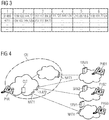
- Fig. 3 shows a compilation of multiple binding entries in a binding table.
- the binding table has in a first column 1 an identification of the communication system-external network element.
- the communication system-external network element or the communication terminal is characterized by its phone number.
- a respective binding entry 31488, 4711 is one within its own network area or within the own communication system valid network address or IP address entered.
- an external network address valid for a first network operator or ISP is entered in the third column 3, and an external network address valid for a second network operator is entered in the fourth column 4.
- Fig. 4 shows a communication system CN, consisting of a communication device CLT to which a plurality of communication terminals are connected.
- a communication terminal PHA is shown by way of example.
- a first, a second and a third network address converting network nodes NAT1, NAT2, NAT3 are provided.
- a corresponding network node NAT1, NAT2, NAT3 is thus also determined via which the call is routed.
- a selection of the associated external network address is implicit.
- the inventive method for the management of communication links takes over the corresponding selection for the communication user to be called.
Landscapes
- Engineering & Computer Science (AREA)
- Computer Networks & Wireless Communication (AREA)
- Signal Processing (AREA)
- Business, Economics & Management (AREA)
- General Business, Economics & Management (AREA)
- Multimedia (AREA)
- Data Exchanges In Wide-Area Networks (AREA)
- Small-Scale Networks (AREA)
Claims (9)
- Procédé de gestion de liaisons de communication dans un système de communication (CN) avec un dispositif de communication (CLT) et un terminal de communication interne (PHA) relié par l'intermédiaire du dispositif de communication (CLT), comprenant les étapes suivantes :a) établissement d'une demande de liaison avec une adresse réseau source valide interne au système de communication par l'intermédiaire d'au moins un noeud de traduction d'adresse réseau (NAT, NAT1, NAT2, NAT3) au niveau d'un terminal de communication externe au système de communication (PHB, PHB1, PHB2, PHB3),b) réception d'une confirmation de liaison avec une adresse réseau valide externe au système de communication attribuée au terminal de communication externe au système de communication (PHB, PHB1, PHB2, PHB3),c) attribution de l'adresse réseau source valide interne au système de communication et de l'adresse réseau valide externe au système de communication à une entrée de liaison attribuée au terminal de communication externe au système de communication (PHB, PHB1, PHB2, PHB3), de sorte qu'à l'intérieur de l'infrastructure de communication formée par le dispositif de communication (CLT), différentes adresses réseau publiques, que le terminal de communication interne (PHA) ou son dispositif de communication de gestion (CLT) doit utiliser, sont déterminées et déposées dans l'entrée de liaison respective, dans lequel les entrées de liaison sont compilées dans un tableau de liaison, etdans lequel pour un établissement d'appel en utilisant le protocole SIP partant du terminal de communication interne (PHA) à un terminal de communication externe au système de communication (PHB, PHB1, PHB2, PHB3) en raison d'une caractéristique de puissance à l'intérieur du dispositif de communication (CLT), une direction correspondante est sélectionnée, laquelle est sélectionnée avec la participation des entrées de liaison du tableau de liaison pour ce partenaire de communication externe.
- Procédé selon la revendication 1, dans lequel les étapes a) à c) sont répétées- pour une pluralité de différentes adresses réseau source valides internes au système de communication du système de communication (CN) et/ou- pour une pluralité de différents éléments de réseau de traduction d'adresse réseau (NAT1, NAT2, NAT3)et la pluralité d'entrées de liaison ainsi créée est entrée dans le tableau de liaisons.
- Procédé selon la revendication 1 ou 2, dans lequel un environnement de communication pour le terminal de communication interne (PHA) comprend plus d'un accès au réseau de données mondial et/ou plusieurs accès à plusieurs fournisseurs SIP et/ou plus d'un noeud (NAT, NAT1, NAT2, NAT3).
- Procédé selon l'une quelconque des revendications précédentes, dans lequel à l'intérieur de l'infrastructure de communication formée par le dispositif de communication (CLT), le terminal de communication interne (PHA) ou son dispositif de communication de gestion (CLT) doit utiliser les différentes adresses réseau publiques pour communiquer avec les plusieurs terminaux de communication externes (PHB, PHB1, PHB2, PHB3) par l'intermédiaire des différentes zones de réseau ou différents noeuds (NAT, NAT1, NAT2, NAT3).
- Procédé selon l'une quelconque des revendications précédentes, dans lequel dans le tableau de liaison pour l'attribution de l'adresse réseau source valide interne au système de communication et de l'adresse réseau valide externe au système de communication à l'entrée de liaison attribuée au terminal de communication externe au système de communication (PHB, PHB1, PHB2, PHB3), plusieurs entrées de liaison sont regroupées et le tableau de liaison présente une identification du terminal de communication externe au système de communication (PHB, PHB1, PHB2, PHB3) sous forme de son numéro d'appel.
- Procédé selon la revendication 5, dans lequel le tableau de liaison présente l'identification du terminal de communication externe au système de communication (PHB, PHB1, PHB2, PHB3) dans une première colonne et dans une deuxième colonne du tableau de liaison pour une entrée de liaison respective dans la première colonne, une adresse IP ou adresse réseau valide à l'intérieur de la propre zone de réseau ou à l'intérieur du propre système de communication.
- Procédé selon la revendication 6, dans lequel une adresse réseau externe valide pour un premier exploitant de réseau ou ISP est entrée dans une troisième colonne du tableau de liaison pour une entrée de liaison respective dans la première colonne, et une adresse réseau externe valide pour un deuxième exploitant de réseau est entrée dans une quatrième colonne.
- Procédé selon la revendication 7, dans lequel d'autres adresses réseau, lesquelles adressent par exemple d'autres exploitants de réseau, sont prévues dans des cinquième et sixième colonnes du tableau de liaison.
- Produit de programme informatique avec code de programme pour la réalisation du procédé selon l'une quelconque des revendications précédentes, lorsque le produit de programme informatique est exécuté sur un dispositif de communication (CLT) pour la gestion d'un terminal de communication (PHA).
Applications Claiming Priority (2)
| Application Number | Priority Date | Filing Date | Title |
|---|---|---|---|
| DE102006030591A DE102006030591A1 (de) | 2006-07-03 | 2006-07-03 | Verfahren zur Verwaltung von Kommunikationsverbindungen |
| PCT/EP2007/056530 WO2008003644A1 (fr) | 2006-07-03 | 2007-06-29 | Procédé de gestion de liaisons de communication par l'intermédiaire de noeuds de traduction d'adresse réseau |
Publications (2)
| Publication Number | Publication Date |
|---|---|
| EP2036313A1 EP2036313A1 (fr) | 2009-03-18 |
| EP2036313B1 true EP2036313B1 (fr) | 2018-10-03 |
Family
ID=38617964
Family Applications (1)
| Application Number | Title | Priority Date | Filing Date |
|---|---|---|---|
| EP07786915.4A Active EP2036313B1 (fr) | 2006-07-03 | 2007-06-29 | Procédé de gestion de liaisons de communication par l'intermédiaire de noeuds de traduction d'adresse réseau |
Country Status (5)
| Country | Link |
|---|---|
| US (1) | US8045579B2 (fr) |
| EP (1) | EP2036313B1 (fr) |
| CN (1) | CN101485179B (fr) |
| DE (1) | DE102006030591A1 (fr) |
| WO (1) | WO2008003644A1 (fr) |
Families Citing this family (3)
| Publication number | Priority date | Publication date | Assignee | Title |
|---|---|---|---|---|
| US8343653B2 (en) * | 2009-11-30 | 2013-01-01 | Samsung Sdi Co., Ltd. | Secondary battery |
| KR101884713B1 (ko) * | 2012-07-20 | 2018-08-30 | 삼성전자주식회사 | 홈 네트워크 시스템 및 상기 시스템에서의 공유기의 네트워크 설정 방법 |
| CN105991957A (zh) * | 2015-03-04 | 2016-10-05 | 中国移动通信集团公司 | 一种双向视频的传输方法及装置 |
Family Cites Families (9)
| Publication number | Priority date | Publication date | Assignee | Title |
|---|---|---|---|---|
| US8224985B2 (en) * | 2005-10-04 | 2012-07-17 | Sony Computer Entertainment Inc. | Peer-to-peer communication traversing symmetric network address translators |
| DE60331426D1 (de) * | 2003-07-14 | 2010-04-08 | Alcatel Lucent | Verfahren zum Aufbau einer Verbindung |
| TWI257217B (en) * | 2003-11-10 | 2006-06-21 | Inst Information Industry | Method to detect the form of network address translation |
| CN100440850C (zh) | 2003-12-24 | 2008-12-03 | 华为技术有限公司 | 多媒体业务网络地址转换穿越的方法及其系统 |
| CN100399768C (zh) * | 2003-12-24 | 2008-07-02 | 华为技术有限公司 | 实现网络地址转换穿越的方法、系统 |
| US7570636B2 (en) * | 2004-06-29 | 2009-08-04 | Damaka, Inc. | System and method for traversing a NAT device for peer-to-peer hybrid communications |
| US7543064B2 (en) * | 2004-09-30 | 2009-06-02 | Logitech Europe S.A. | Multiplayer peer-to-peer connection across firewalls and network address translators using a single local port on the local host |
| US7483393B2 (en) * | 2004-12-07 | 2009-01-27 | Cisco Technology, Inc. | Method and apparatus for discovering internet addresses |
| US7920549B2 (en) * | 2005-07-20 | 2011-04-05 | Verizon Business Global Llc | Method and system for providing secure media gateways to support interdomain traversal |
-
2006
- 2006-07-03 DE DE102006030591A patent/DE102006030591A1/de not_active Ceased
-
2007
- 2007-06-29 US US12/308,733 patent/US8045579B2/en active Active
- 2007-06-29 CN CN2007800253111A patent/CN101485179B/zh not_active Expired - Fee Related
- 2007-06-29 WO PCT/EP2007/056530 patent/WO2008003644A1/fr active Application Filing
- 2007-06-29 EP EP07786915.4A patent/EP2036313B1/fr active Active
Non-Patent Citations (1)
| Title |
|---|
| None * |
Also Published As
| Publication number | Publication date |
|---|---|
| WO2008003644A1 (fr) | 2008-01-10 |
| CN101485179B (zh) | 2013-07-24 |
| US8045579B2 (en) | 2011-10-25 |
| US20100014522A1 (en) | 2010-01-21 |
| DE102006030591A1 (de) | 2008-01-10 |
| EP2036313A1 (fr) | 2009-03-18 |
| CN101485179A (zh) | 2009-07-15 |
Similar Documents
| Publication | Publication Date | Title |
|---|---|---|
| DE10353925B4 (de) | Verfahren zum Austausch von Daten zwischen zwei Hosts | |
| EP2193649B1 (fr) | Procédé et dispositif pour connecter des terminaux de communication en mode paquet | |
| DE102015004668B4 (de) | Aufgeteilte netzwerkadressenübersetzung | |
| EP2036313B1 (fr) | Procédé de gestion de liaisons de communication par l'intermédiaire de noeuds de traduction d'adresse réseau | |
| DE102005043239B4 (de) | Verfahren zum Aufbau und Verwalten einer Verbindung | |
| EP1878205B1 (fr) | Procede et dispositif servant a la conversion d'adresses de protocole internet a l'interieur d'un reseau de communication | |
| EP1317820A1 (fr) | Procede pour etablir des liaisons avec des qualites de service predefinies dans un reseau de communication oriente paquet, a l'aide d'un gestionnaire de ressources | |
| DE102005035733A1 (de) | Verfahren zum Datenaustausch zwischen Netzelementen | |
| EP1421766A1 (fr) | Pre-traitement d'adresses nat | |
| EP1227632B1 (fr) | Procédé pour faire fonctionner un réseau de communications multimedia | |
| WO2003028333A1 (fr) | Unite de connexion de reseaux et systeme de communication pour liaisons de communication en temps reel | |
| WO2004100498A1 (fr) | Procede d'echange de donnees entre des elements de reseau dans des reseaux a differentes zones d'adresse | |
| WO2012130263A1 (fr) | Procédé d'adressage de messages dans un réseau d'ordinateurs | |
| EP2279603B1 (fr) | Dispositif et procédé pour retraiter une liaison multimédia ainsi que système de communication associé, support de mémoire numérique, produit de programme informatique et programme informatique | |
| EP1841164B1 (fr) | Système, procédé et dispositif de connexion pour configurer des routeurs NAT | |
| EP1559241B1 (fr) | Procédé et dispositif pour échanger des données par une liaison tunnel | |
| EP2108229B1 (fr) | Procédé et arrangement de communication pour transporter des données multimédia entre des terminaux ip dans un réseau local d'un wan | |
| EP1383295B1 (fr) | Méthode de mappage d'adresses dans des réseaux de paquets et appareil de mappage pour réseaux de communication | |
| EP1924072A1 (fr) | Établissement d'une connexion dans un réseau IP privé sans contacter un serveur STUN public | |
| EP1522183B1 (fr) | Procédé de conversion d'adresses dans de réseaux de commutation par paquets et element de commande pour réseaux de communication | |
| WO2006042800A1 (fr) | Etablissement d'une liaison de service entre un terminal et un premier element reseau ayant des versions de protocole ip differentes | |
| WO2004032474A1 (fr) | Unite de commande integree |
Legal Events
| Date | Code | Title | Description |
|---|---|---|---|
| PUAI | Public reference made under article 153(3) epc to a published international application that has entered the european phase |
Free format text: ORIGINAL CODE: 0009012 |
|
| 17P | Request for examination filed |
Effective date: 20081204 |
|
| AK | Designated contracting states |
Kind code of ref document: A1 Designated state(s): AT BE BG CH CY CZ DE DK EE ES FI FR GB GR HU IE IS IT LI LT LU LV MC MT NL PL PT RO SE SI SK TR |
|
| AX | Request for extension of the european patent |
Extension state: AL BA HR MK RS |
|
| DAX | Request for extension of the european patent (deleted) | ||
| RBV | Designated contracting states (corrected) |
Designated state(s): DE FR GB IT |
|
| RAP1 | Party data changed (applicant data changed or rights of an application transferred) |
Owner name: SIEMENS ENTERPRISE COMMUNICATIONS GMBH & CO. KG |
|
| 17Q | First examination report despatched |
Effective date: 20131031 |
|
| RAP1 | Party data changed (applicant data changed or rights of an application transferred) |
Owner name: UNIFY GMBH & CO. KG |
|
| RAP1 | Party data changed (applicant data changed or rights of an application transferred) |
Owner name: UNIFY GMBH & CO. KG |
|
| GRAP | Despatch of communication of intention to grant a patent |
Free format text: ORIGINAL CODE: EPIDOSNIGR1 |
|
| INTG | Intention to grant announced |
Effective date: 20180424 |
|
| GRAS | Grant fee paid |
Free format text: ORIGINAL CODE: EPIDOSNIGR3 |
|
| GRAA | (expected) grant |
Free format text: ORIGINAL CODE: 0009210 |
|
| AK | Designated contracting states |
Kind code of ref document: B1 Designated state(s): DE FR GB IT |
|
| REG | Reference to a national code |
Ref country code: GB Ref legal event code: FG4D Free format text: NOT ENGLISH |
|
| REG | Reference to a national code |
Ref country code: DE Ref legal event code: R096 Ref document number: 502007016423 Country of ref document: DE |
|
| REG | Reference to a national code |
Ref country code: DE Ref legal event code: R097 Ref document number: 502007016423 Country of ref document: DE |
|
| PG25 | Lapsed in a contracting state [announced via postgrant information from national office to epo] |
Ref country code: IT Free format text: LAPSE BECAUSE OF FAILURE TO SUBMIT A TRANSLATION OF THE DESCRIPTION OR TO PAY THE FEE WITHIN THE PRESCRIBED TIME-LIMIT Effective date: 20181003 |
|
| PLBE | No opposition filed within time limit |
Free format text: ORIGINAL CODE: 0009261 |
|
| STAA | Information on the status of an ep patent application or granted ep patent |
Free format text: STATUS: NO OPPOSITION FILED WITHIN TIME LIMIT |
|
| 26N | No opposition filed |
Effective date: 20190704 |
|
| REG | Reference to a national code |
Ref country code: DE Ref legal event code: R082 Ref document number: 502007016423 Country of ref document: DE Representative=s name: SCHAAFHAUSEN PATENTANWAELTE PARTNERSCHAFTSGESE, DE |
|
| REG | Reference to a national code |
Ref country code: DE Ref legal event code: R079 Ref document number: 502007016423 Country of ref document: DE Free format text: PREVIOUS MAIN CLASS: H04L0029120000 Ipc: H04L0067286900 |
|
| PGFP | Annual fee paid to national office [announced via postgrant information from national office to epo] |
Ref country code: FR Payment date: 20230622 Year of fee payment: 17 Ref country code: DE Payment date: 20230620 Year of fee payment: 17 |
|
| PGFP | Annual fee paid to national office [announced via postgrant information from national office to epo] |
Ref country code: GB Payment date: 20230622 Year of fee payment: 17 |