EP2035707B1 - Hydraulic pump - Google Patents
Hydraulic pump Download PDFInfo
- Publication number
- EP2035707B1 EP2035707B1 EP20070787017 EP07787017A EP2035707B1 EP 2035707 B1 EP2035707 B1 EP 2035707B1 EP 20070787017 EP20070787017 EP 20070787017 EP 07787017 A EP07787017 A EP 07787017A EP 2035707 B1 EP2035707 B1 EP 2035707B1
- Authority
- EP
- European Patent Office
- Prior art keywords
- passage
- pump
- delivery
- valve
- pump according
- Prior art date
- Legal status (The legal status is an assumption and is not a legal conclusion. Google has not performed a legal analysis and makes no representation as to the accuracy of the status listed.)
- Not-in-force
Links
Images


Classifications
-
- F—MECHANICAL ENGINEERING; LIGHTING; HEATING; WEAPONS; BLASTING
- F04—POSITIVE - DISPLACEMENT MACHINES FOR LIQUIDS; PUMPS FOR LIQUIDS OR ELASTIC FLUIDS
- F04B—POSITIVE-DISPLACEMENT MACHINES FOR LIQUIDS; PUMPS
- F04B53/00—Component parts, details or accessories not provided for in, or of interest apart from, groups F04B1/00 - F04B23/00 or F04B39/00 - F04B47/00
- F04B53/16—Casings; Cylinders; Cylinder liners or heads; Fluid connections
-
- F—MECHANICAL ENGINEERING; LIGHTING; HEATING; WEAPONS; BLASTING
- F04—POSITIVE - DISPLACEMENT MACHINES FOR LIQUIDS; PUMPS FOR LIQUIDS OR ELASTIC FLUIDS
- F04B—POSITIVE-DISPLACEMENT MACHINES FOR LIQUIDS; PUMPS
- F04B1/00—Multi-cylinder machines or pumps characterised by number or arrangement of cylinders
- F04B1/12—Multi-cylinder machines or pumps characterised by number or arrangement of cylinders having cylinder axes coaxial with, or parallel or inclined to, main shaft axis
- F04B1/14—Multi-cylinder machines or pumps characterised by number or arrangement of cylinders having cylinder axes coaxial with, or parallel or inclined to, main shaft axis having stationary cylinders
-
- F—MECHANICAL ENGINEERING; LIGHTING; HEATING; WEAPONS; BLASTING
- F04—POSITIVE - DISPLACEMENT MACHINES FOR LIQUIDS; PUMPS FOR LIQUIDS OR ELASTIC FLUIDS
- F04B—POSITIVE-DISPLACEMENT MACHINES FOR LIQUIDS; PUMPS
- F04B53/00—Component parts, details or accessories not provided for in, or of interest apart from, groups F04B1/00 - F04B23/00 or F04B39/00 - F04B47/00
- F04B53/10—Valves; Arrangement of valves
Definitions
- the present invention relates to a hydraulic pump, and specifically to a hydraulic piston pump.
- a fundamental aspect of pumps used in portable controllers is the discharge from the circuits, since the pressures generated are very large and the pressure must be reduced very quickly in the circuit. This function is usually performed by a discharge valve included in the circuit, but this tends to have a negative effect on both the weight of the device and the complexity of construction of the circuit.
- EP-A-1 586 775 which is considered to represent the closest prior art, which shows an axial piston hydraulic pump, comprising at least one piston 121, coupled by suitable transmission means 150 to drive means 111 and slidable with a reciprocating motion inside a cylinder 122, the said cylinder 122 communicating with a fluid intake passage 40 and a fluid delivery passage 31, one-way means 42 of controlling the flow of the fluid being provided in both passages, the delivery passage 31 communicating with a delivery manifold 120P positioned downstream of the said one-way flow control means 42, wherein said manifold 120P communicates with a switching valve for selectively communicating/blocking the first bypass oil passage 71.
- an axial piston device comprising a housing 10 having a hollow housing body 20 opened at a first end thereof and a plate 30 disposed at the first end of said housing body 20.
- a pump shaft 40 rotatably supported on an axis by said housing body 20 and by said plate 30; a cylinder block 51 supported by said pump shaft ; in which said plate 30 is provided with a pair of first oil passages 101 a and 101b provided with a first ends communicating with a discharge port 50a and with a suction port 50b of said cylinder 51 and second ends opened to the outer surface of said plate 30, and a drain oil passage 110 in order to allow to at least one of said first oil passages 101 a, 101 b to communicate with an oil sump 11.
- the said drain oil passage 110 is provided with a rotary shutoff valve 130 which can be selectively switched to a first closure position in which the drain oil passage 110 is closed to a second position in which said passage 110 opened.
- a reciprocating piston pump is known of the type wherein discharge flow from the pump working chamber is controlled by a spring-biased check valve.
- a hydraulically actuated tool comprising a frame; a hydraulic fluid pump connected to the frame; a ram movably connected to the frame and adapted to be moved relative to the frame by hydraulic fluid pumped by the pump; and a hydraulic fluid reservoir connected to the pump.
- the object of the present invention is therefore to provide a hydraulic piston pump as claimed in claim 1 in which the discharge of the hydraulic circuit does not give rise to structural complications of the circuit or a significant increase in the volume and overall weight of the device
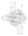
- FIG. 1 shows an embodiment of the pump according to the present invention
- the number 1 indicates the body of the pump, in which the two cylindrical chambers 101 are formed.
- Each chamber 101 has an intake aperture 111 communicating with a passage 151 by means of a valve 121 comprising a seat 141 and a ball plug 131.
- the cylindrical chamber 101 also has a delivery channel 161, communicating with the delivery passage 301 in the way which is explained more fully below.
- the said shaft 3 is mounted inside the cavity 104 of the cover 4 of the pump by means of the thrust bearing 203.
- each piston 2 is inserted into an annular element 212 which interacts with a coil spring 302 placed in an annular groove 201 formed in the body 1 around each of the cylindrical cavities 101.
- the manifold 301 is formed in the body 1 between the two cavities 101, with its axis perpendicular to that of the said cavities; the passage 401, in which the plug 411 is located, is formed in a plane parallel to that in which the said manifold 301 lies.
- FIG 2 the pump according to the invention is shown in section along the line II-II of Figure 1 ; identical parts have been given identical numerals.
- the figure shows how both the cylinders 101 communicate with the intake apertures 111 and also with the delivery passages 161.
- a non-return valve 501 which comprises a seat 511 in which is positioned a ball plug 521 loaded by a spring 531 whose opposite end bears on a bolt 541.
- the valve 501 communicates with a channel 551, which opens directly into the delivery manifold 301, while in the other case the valve 501 communicates with a channel 561 which opens into the passage 351, and the fluid reaches the delivery manifold through the non-return valve formed by the plug 321 loaded by the spring 331, whose opposite end bears on the threaded portion 361 of the joint 341 coupled to the said delivery manifold 301.
- a channel 611 communicating with a maximum pressure valve 601 opens into the delivery manifold 301; another maximum pressure valve 701 is connected to the channel 621 which opens into the passage 351.
- FIG 3 is another sectional view of the pump according to the invention, along the line III-III of Figure 2 ; identical parts have been given identical numerals.
- the delivery manifold 301 communicates, via a channel 461, with the passage 401 into which is introduced the plug 411, which in this case has the same proportions as the piston 2, and is provided with a mushroom-shaped head 421 like that of the piston; the passage is closed at the end facing the outside of the pump by a stopper 431 provided with the axial hole 441.
- the pump as shown in the figures described above is a pump which is immersed in an oil reservoir, from which the oil is drawn through the intake apertures 111 and the corresponding valves 121.
- the motor When the motor is operated, the pressure in the circuit rises rapidly, due to the action of both pistons 2.
- the set value of the valve 701 positioned in the circuit upstream of the non-return valve 321 of the delivery manifold 301 is reached, the portion of the circuit connected to the said valve goes into discharge mode, and the work of compression performed on the fluid is effectively carried out only by the piston which discharges through the passage 551 directly into the delivery manifold 301.
- valve 701 is preferably set to discharge at a pressure in the range from 30 to 70 atmospheres, and preferably about 50 atmospheres.
- the motor that can be used in these conditions is a motor which can develop a power in the range from 500 to 1000 watts, and in particular a power of 750 watts. This makes it possible to use the pump with very small motors, and thus facilitates the use of the pump in transportable power controllers.
- the pressure drop due to the constricted flow of the oil in the intermediate space created between the plug 411 and the passage 401 is very small with respect to the operating pressure of the pump.
- the motor is switched off, the fluid is rapidly discharged from the circuit, and the use of a static member simplifies the construction of the circuit and avoids the introduction of an additional part which would make the device heavier.
- constricted flow member makes it possible to achieve excellent safety margins in operation; this is because, whereas a constricted flow passage having a similar cross section to that used in the case illustrated herein would be subject to a high risk of clogging, the assembly of the passage 401 and the plug 411 provides better control of the constricted flow. Furthermore, the passage 401 is easily accessible, and its maintenance can be facilitated by the removal of the plug 411.
- the plug 411 is made to be entirely similar to the piston 2 used in each of the cylindrical chambers 101 of the pump; the result of this arrangement is that, during construction, the tool used to form the passage 401 and that used to form the cylindrical chambers are identical, and the process of forming the pistons 2 can also be used to form the appropriate plug used in the constricted flow member.
- the pump designed in this way is highly efficient when used at high pressures, and particularly in equipment such as portable power controllers.
Description
- The present invention relates to a hydraulic pump, and specifically to a hydraulic piston pump.
- The characteristics of a pump are essentially determined by the application for which it is intended, and consequently there are numerous different embodiments of these devices, designed to meet different requirements. In particular, the research which led to the present invention was conducted in the field of hydraulic pumps which are intended to deliver fluid at high pressures, up to several hundred atmospheres, and which are made with small dimensions, so that they can be used in easily transportable power controllers.
- There are many problems associated with the construction of this kind of pump; in particular, it is important for the structure of the device to be extremely compact and light, so as to avoid negative effects on the volume and weight of the controller in which it is to be used. Clearly, the chosen type of construction must not have negative effects on essential characteristics such as safety and operating reliability.
- Typically, a fundamental aspect of pumps used in portable controllers is the discharge from the circuits, since the pressures generated are very large and the pressure must be reduced very quickly in the circuit. This function is usually performed by a discharge valve included in the circuit, but this tends to have a negative effect on both the weight of the device and the complexity of construction of the circuit.
- From
EP-A-1 586 775 which is considered to represent the closest prior art, which shows an axial piston hydraulic pump, comprising at least onepiston 121, coupled by suitable transmission means 150 to drivemeans 111 and slidable with a reciprocating motion inside a cylinder 122, the said cylinder 122 communicating with a fluid intake passage 40 and a fluid delivery passage 31, one-way means 42 of controlling the flow of the fluid being provided in both passages, the delivery passage 31 communicating with a delivery manifold 120P positioned downstream of the said one-way flow control means 42, wherein said manifold 120P communicates with a switching valve for selectively communicating/blocking the first bypass oil passage 71. - From
US 2005/053478 A1 an axial piston device is described comprising a housing 10 having a hollow housing body 20 opened at a first end thereof and a plate 30 disposed at the first end of said housing body 20. A pump shaft 40 rotatably supported on an axis by said housing body 20 and by said plate 30; a cylinder block 51 supported by said pump shaft ; in which said plate 30 is provided with a pair of first oil passages 101 a and 101b provided with a first ends communicating with a discharge port 50a and with a suction port 50b of said cylinder 51 and second ends opened to the outer surface of said plate 30, and a drain oil passage 110 in order to allow to at least one of said first oil passages 101 a, 101 b to communicate with an oil sump 11. The said drain oil passage 110 is provided with a rotary shutoff valve 130 which can be selectively switched to a first closure position in which the drain oil passage 110 is closed to a second position in which said passage 110 opened. - From
US-A-3 033 119 a reciprocating piston pump is known of the type wherein discharge flow from the pump working chamber is controlled by a spring-biased check valve. - From
EP-A-1 176 308 a hydraulically actuated tool is known comprising a frame; a hydraulic fluid pump connected to the frame; a ram movably connected to the frame and adapted to be moved relative to the frame by hydraulic fluid pumped by the pump; and a hydraulic fluid reservoir connected to the pump. - The object of the present invention is therefore to provide a hydraulic piston pump as claimed in
claim 1 in which the discharge of the hydraulic circuit does not give rise to structural complications of the circuit or a significant increase in the volume and overall weight of the device - Further advantages and features of the device according to the present invention will be made clear by the following detailed description of an embodiment of the invention, provided, with reference to the attached sheets of drawings, in which:
-
Figure 1 is a sectional view of an embodiment of the pump according to the present invention; -
Figure 2 is a view in cross section along the line II-II ofFigure 1 ; and -
Figure 3 is a sectional view along the line III-III ofFigure 2 . -
Figure 1 shows an embodiment of the pump according to the present invention; thenumber 1 indicates the body of the pump, in which the twocylindrical chambers 101 are formed. Eachchamber 101 has anintake aperture 111 communicating with apassage 151 by means of avalve 121 comprising aseat 141 and aball plug 131. Thecylindrical chamber 101 also has adelivery channel 161, communicating with thedelivery passage 301 in the way which is explained more fully below. Inside eachcylindrical chamber 101 there is therod 102 of apiston 2 which is slidable with a reciprocating motion, the end of the rod opposite the end inserted into thecavity 101 being provided with a mushroom-shaped head 202, which is in contact with the surface of thebearing 303 keyed on theinclined shaft 123 projecting from theplate 103 connected to thedrive shaft 3. The saidshaft 3 is mounted inside thecavity 104 of the cover 4 of the pump by means of the thrust bearing 203. - The
head 202 of eachpiston 2 is inserted into anannular element 212 which interacts with acoil spring 302 placed in anannular groove 201 formed in thebody 1 around each of thecylindrical cavities 101. Themanifold 301 is formed in thebody 1 between the twocavities 101, with its axis perpendicular to that of the said cavities; thepassage 401, in which theplug 411 is located, is formed in a plane parallel to that in which the saidmanifold 301 lies. - In
Figure 2 , the pump according to the invention is shown in section along the line II-II ofFigure 1 ; identical parts have been given identical numerals. The figure shows how both thecylinders 101 communicate with theintake apertures 111 and also with thedelivery passages 161. In each delivery passage there is anon-return valve 501, which comprises aseat 511 in which is positioned aball plug 521 loaded by aspring 531 whose opposite end bears on abolt 541. In one case, thevalve 501 communicates with achannel 551, which opens directly into thedelivery manifold 301, while in the other case thevalve 501 communicates with achannel 561 which opens into thepassage 351, and the fluid reaches the delivery manifold through the non-return valve formed by theplug 321 loaded by thespring 331, whose opposite end bears on the threadedportion 361 of thejoint 341 coupled to the saiddelivery manifold 301. Achannel 611 communicating with amaximum pressure valve 601 opens into thedelivery manifold 301; anothermaximum pressure valve 701 is connected to thechannel 621 which opens into thepassage 351. -
Figure 3 is another sectional view of the pump according to the invention, along the line III-III ofFigure 2 ; identical parts have been given identical numerals. As can be seen, thedelivery manifold 301 communicates, via achannel 461, with thepassage 401 into which is introduced theplug 411, which in this case has the same proportions as thepiston 2, and is provided with a mushroom-shaped head 421 like that of the piston; the passage is closed at the end facing the outside of the pump by astopper 431 provided with theaxial hole 441. - The operation of the pump according to the present invention will be made clear by the following description. The pump as shown in the figures described above is a pump which is immersed in an oil reservoir, from which the oil is drawn through the
intake apertures 111 and thecorresponding valves 121. When the motor is operated, the pressure in the circuit rises rapidly, due to the action of bothpistons 2. When the set value of thevalve 701 positioned in the circuit upstream of thenon-return valve 321 of thedelivery manifold 301 is reached, the portion of the circuit connected to the said valve goes into discharge mode, and the work of compression performed on the fluid is effectively carried out only by the piston which discharges through thepassage 551 directly into thedelivery manifold 301. - Thus very high pressures of about 1000 atmospheres can be achieved, with drive means of very limited power; the
valve 701 is preferably set to discharge at a pressure in the range from 30 to 70 atmospheres, and preferably about 50 atmospheres. The motor that can be used in these conditions is a motor which can develop a power in the range from 500 to 1000 watts, and in particular a power of 750 watts. This makes it possible to use the pump with very small motors, and thus facilitates the use of the pump in transportable power controllers. - According to the principal innovative feature of the present invention, the decision was made to provide a constricted flow member for the discharge of the circuit when the motor is switched off, in order to lighten the system while also simplifying the hydraulic circuit. During the operation of the pump, the pressure drop due to the constricted flow of the oil in the intermediate space created between the
plug 411 and thepassage 401 is very small with respect to the operating pressure of the pump. However, when the motor is switched off, the fluid is rapidly discharged from the circuit, and the use of a static member simplifies the construction of the circuit and avoids the introduction of an additional part which would make the device heavier. - The specific design of the constricted flow member makes it possible to achieve excellent safety margins in operation; this is because, whereas a constricted flow passage having a similar cross section to that used in the case illustrated herein would be subject to a high risk of clogging, the assembly of the
passage 401 and theplug 411 provides better control of the constricted flow. Furthermore, thepassage 401 is easily accessible, and its maintenance can be facilitated by the removal of theplug 411. Advantageously, theplug 411 is made to be entirely similar to thepiston 2 used in each of thecylindrical chambers 101 of the pump; the result of this arrangement is that, during construction, the tool used to form thepassage 401 and that used to form the cylindrical chambers are identical, and the process of forming thepistons 2 can also be used to form the appropriate plug used in the constricted flow member. - The pump designed in this way is highly efficient when used at high pressures, and particularly in equipment such as portable power controllers.
Claims (10)
- An axial piston hydraulic pump comprising at least one piston (2), coupled by transmission means (103, 113) to drive means (3) and slidable with a reciprocating motion inside a cylinder (101), the cylinder (101) communicating with a fluid intake passage (151) and a fluid delivery passage (161), a one-way valve (121, 501) in said fluid intake passage and another one-way valve in said fluid delivery passage controlling a flow of a fluid there through, the delivery passage (161) communicating with a delivery manifold (301) positioned downstream of the one-way valve (501) of the delivery passage, characterized by the fact that the delivery manifold (301) communicates with a constricted flow discharge member (401, 411,) which permits the fluid flow there through during operation of the pump at a pressure drop which is very small relative to the operating pressure of the pump, the constricted flow discharge member (401, 411) communicating at all times with a discharge aperture (441) connected to atmosphere, wherein when the pump is switched off, the constricted discharge member (401,411) enables the fluid to be rapidly discharged from the pump.
- The pump according to Claim 1, in which the said constricted flow discharge member (401,411) comprises a passage (401) in communication with the said delivery manifold (301) at one end and provided with a discharge aperture (441), an insert placed in said passage (401) whose cross section is complementary to said passage (401).
- The pump according to Claim 2, in which the shape and dimensions of the said passage (401) are identical to those of the said piston (2).
- The pump according to any one of the preceding Claims 1 to 3, in which the said pump comprises a body (1) of metallic material, in which the said cylinder (101) and the said intake (151) and delivery (161, 301) passages are formed, and in which the said constricted flow member (401, 411,) is positioned.
- The pump according to any one of the preceding Claims 1 to 4, in which the said delivery manifold (301) is provided with a maximum pressure valve (601) set to a given pressure level.
- The pump according to Claim 5, in which the said pressure level is in the range from 50662,50 kPa (500 atm) to 101325,00 kPa (1000 atm), and is 72954,00 kPa (720 atm).
- The pump according to any one of the preceding Claims 1 to 6, characterized in that said axial piston hydraulic pump comprises at least two pistons (2), each slidable with a reciprocating motion inside the cylinder (101), and in which the delivery manifold (301) is provided with a non-return valve (321, 331), one of two delivery passages (161) being in communication with the said delivery manifold (301) downstream of the said valve (321, 331), the other passage (161) communicating with a portion (351) of the said manifold (301) upstream of the said valve (321, 331), the portion (351) of the delivery manifold (301) having a discharge valve (701) set to a given pressure level.
- The pump according to Claim 7, in which the said pressure level is 5066,25 kPa (50 atm).
- The pump according to Claim 7 or 8 in which a maximum pressure valve (601) is provided which communicates with the said delivery manifold (301) downstream of the non-return valve (321, 331).
- The pump according to any one of Claims 1 to 9, in which the said transmission means comprise an inclined plate (113) placed at a given angle with respect to the axis of the transmission shaft (3) connected to drive means, the said axis of the said shaft (3) being parallel to the axis of the said cylinder (101).
Applications Claiming Priority (2)
| Application Number | Priority Date | Filing Date | Title |
|---|---|---|---|
| IT000071A ITGE20060071A1 (en) | 2006-07-05 | 2006-07-05 | HYDRAULIC PUMP |
| PCT/EP2007/056694 WO2008003705A2 (en) | 2006-07-05 | 2007-07-03 | Hydraulic pump |
Publications (2)
| Publication Number | Publication Date |
|---|---|
| EP2035707A2 EP2035707A2 (en) | 2009-03-18 |
| EP2035707B1 true EP2035707B1 (en) | 2015-04-22 |
Family
ID=38805828
Family Applications (1)
| Application Number | Title | Priority Date | Filing Date |
|---|---|---|---|
| EP20070787017 Not-in-force EP2035707B1 (en) | 2006-07-05 | 2007-07-03 | Hydraulic pump |
Country Status (13)
| Country | Link |
|---|---|
| US (1) | US8303265B2 (en) |
| EP (1) | EP2035707B1 (en) |
| JP (1) | JP5301435B2 (en) |
| KR (1) | KR20090029714A (en) |
| CN (1) | CN101479482B (en) |
| AU (1) | AU2007271190B2 (en) |
| BR (1) | BRPI0713259A2 (en) |
| CA (1) | CA2655185A1 (en) |
| IT (1) | ITGE20060071A1 (en) |
| MX (1) | MX2008016413A (en) |
| RU (1) | RU2443906C2 (en) |
| WO (1) | WO2008003705A2 (en) |
| ZA (1) | ZA200810580B (en) |
Families Citing this family (2)
| Publication number | Priority date | Publication date | Assignee | Title |
|---|---|---|---|---|
| JP5208632B2 (en) * | 2008-09-11 | 2013-06-12 | リューベ株式会社 | Grease pump device |
| IT201900024241A1 (en) * | 2019-12-17 | 2021-06-17 | Mixtron S R L | AXIAL PISTON PUMP WITH INCLINED PLATE |
Family Cites Families (14)
| Publication number | Priority date | Publication date | Assignee | Title |
|---|---|---|---|---|
| US3033119A (en) * | 1959-07-06 | 1962-05-08 | New York Air Brake Co | Pump |
| US3357363A (en) * | 1966-11-15 | 1967-12-12 | Internat Basic Eeonomy Corp | Hydraulic machine |
| SU387136A1 (en) * | 1971-01-21 | 1973-06-21 | AXIAL PISTON PUMP | |
| US3832094A (en) * | 1973-03-23 | 1974-08-27 | Int Basic Economy Corp | Hydraulic pump |
| JPS5540376Y2 (en) * | 1973-05-14 | 1980-09-20 | ||
| JPS56127880U (en) * | 1980-02-28 | 1981-09-29 | ||
| JPH08338357A (en) * | 1995-06-13 | 1996-12-24 | Toyota Autom Loom Works Ltd | Variable displacement type piston pump |
| JP3547900B2 (en) * | 1996-03-22 | 2004-07-28 | 日立建機株式会社 | Axial piston type hydraulic pump |
| JP4282834B2 (en) * | 1999-06-23 | 2009-06-24 | 株式会社日立製作所 | Fluid device |
| DE19928913A1 (en) * | 1999-06-24 | 2001-01-04 | Bosch Gmbh Robert | Piston pump |
| US6453719B1 (en) * | 2000-07-28 | 2002-09-24 | Fci Usa, Inc. | Hydraulic tool with forward surrounding reservoir |
| JP4425590B2 (en) * | 2003-09-09 | 2010-03-03 | 株式会社 神崎高級工機製作所 | Pumping unit |
| EP1586775A3 (en) * | 2004-04-13 | 2011-11-09 | Kanzaki Kokyukoki Mfg. Co., Ltd. | Hydraulic pump unit, hydraulic pump set and working vehicle |
| JP4568807B2 (en) * | 2004-11-16 | 2010-10-27 | 株式会社 神崎高級工機製作所 | Pump device |
-
2006
- 2006-07-05 IT IT000071A patent/ITGE20060071A1/en unknown
-
2007
- 2007-07-03 US US12/307,427 patent/US8303265B2/en not_active Expired - Fee Related
- 2007-07-03 MX MX2008016413A patent/MX2008016413A/en unknown
- 2007-07-03 CA CA002655185A patent/CA2655185A1/en not_active Abandoned
- 2007-07-03 BR BRPI0713259-0A patent/BRPI0713259A2/en not_active IP Right Cessation
- 2007-07-03 RU RU2008149935/06A patent/RU2443906C2/en not_active IP Right Cessation
- 2007-07-03 JP JP2009517260A patent/JP5301435B2/en not_active Expired - Fee Related
- 2007-07-03 WO PCT/EP2007/056694 patent/WO2008003705A2/en active Application Filing
- 2007-07-03 AU AU2007271190A patent/AU2007271190B2/en not_active Ceased
- 2007-07-03 EP EP20070787017 patent/EP2035707B1/en not_active Not-in-force
- 2007-07-03 KR KR1020087029894A patent/KR20090029714A/en active IP Right Grant
- 2007-07-03 CN CN2007800240906A patent/CN101479482B/en not_active Expired - Fee Related
-
2008
- 2008-12-12 ZA ZA200810580A patent/ZA200810580B/en unknown
Also Published As
| Publication number | Publication date |
|---|---|
| JP5301435B2 (en) | 2013-09-25 |
| CN101479482A (en) | 2009-07-08 |
| RU2443906C2 (en) | 2012-02-27 |
| BRPI0713259A2 (en) | 2012-04-03 |
| US20090317274A1 (en) | 2009-12-24 |
| KR20090029714A (en) | 2009-03-23 |
| MX2008016413A (en) | 2009-01-21 |
| CN101479482B (en) | 2012-11-21 |
| JP2009541653A (en) | 2009-11-26 |
| CA2655185A1 (en) | 2008-01-10 |
| WO2008003705A3 (en) | 2008-03-13 |
| WO2008003705A2 (en) | 2008-01-10 |
| ITGE20060071A1 (en) | 2008-01-06 |
| AU2007271190B2 (en) | 2011-12-15 |
| RU2008149935A (en) | 2010-06-27 |
| US8303265B2 (en) | 2012-11-06 |
| EP2035707A2 (en) | 2009-03-18 |
| ZA200810580B (en) | 2010-05-26 |
| AU2007271190A1 (en) | 2008-01-10 |
Similar Documents
| Publication | Publication Date | Title |
|---|---|---|
| JP3555723B2 (en) | Hydraulic operating unit and method of exhausting hydraulic operating unit | |
| CN101379296B (en) | Variable displacement variable pressure vane pump system | |
| KR20100022966A (en) | Diaphragm pump position control with offset valve axis | |
| CN101680461A (en) | Attenuator for damping pressure fluctuations in a hydraulic system | |
| US20030077190A1 (en) | Reciprocating pump and check valve | |
| JP2009191754A (en) | Variable displacement gear pump | |
| EA014972B1 (en) | Pressure compensated pump | |
| EP2035707B1 (en) | Hydraulic pump | |
| CA2379641A1 (en) | Double acting, two-stage pump | |
| KR20220010769A (en) | Spool valves used in variable vane pumps | |
| US6162024A (en) | Constant horsepower continuously variable volume pump | |
| CN110831750A (en) | Device for controlling switching of hydraulic cylinder | |
| KR100329158B1 (en) | Apparatus for relieving start shock in compressors | |
| JP6539231B2 (en) | Swash plate type piston pump | |
| CN113383158A (en) | Hydraulic device with turbine | |
| KR20000013545U (en) | Compressor Shock Absorber | |
| CN111022279B (en) | Reciprocating plunger pump | |
| US5201175A (en) | Hydraulic actuating system and method | |
| KR100712948B1 (en) | A oil pressure pump | |
| JP3809393B2 (en) | Control device for variable displacement piston pump | |
| JPS6125916B2 (en) | ||
| US9689409B2 (en) | Passive piston hydraulic device with partition | |
| JP2002021740A (en) | Drain discharging structure for pump motor | |
| KR20190141933A (en) | Oil pump system | |
| JPH0465268B2 (en) |
Legal Events
| Date | Code | Title | Description |
|---|---|---|---|
| PUAI | Public reference made under article 153(3) epc to a published international application that has entered the european phase |
Free format text: ORIGINAL CODE: 0009012 |
|
| 17P | Request for examination filed |
Effective date: 20081211 |
|
| AK | Designated contracting states |
Kind code of ref document: A2 Designated state(s): AT BE BG CH CY CZ DE DK EE ES FI FR GB GR HU IE IS IT LI LT LU LV MC MT NL PL PT RO SE SI SK TR |
|
| AX | Request for extension of the european patent |
Extension state: AL BA HR MK RS |
|
| 17Q | First examination report despatched |
Effective date: 20090525 |
|
| DAX | Request for extension of the european patent (deleted) | ||
| RIC1 | Information provided on ipc code assigned before grant |
Ipc: F04B 1/14 20060101ALI20140930BHEP Ipc: F04B 53/10 20060101ALI20140930BHEP Ipc: F04B 53/16 20060101AFI20140930BHEP |
|
| GRAP | Despatch of communication of intention to grant a patent |
Free format text: ORIGINAL CODE: EPIDOSNIGR1 |
|
| INTG | Intention to grant announced |
Effective date: 20141118 |
|
| GRAS | Grant fee paid |
Free format text: ORIGINAL CODE: EPIDOSNIGR3 |
|
| GRAA | (expected) grant |
Free format text: ORIGINAL CODE: 0009210 |
|
| AK | Designated contracting states |
Kind code of ref document: B1 Designated state(s): AT BE BG CH CY CZ DE DK EE ES FI FR GB GR HU IE IS IT LI LT LU LV MC MT NL PL PT RO SE SI SK TR |
|
| REG | Reference to a national code |
Ref country code: GB Ref legal event code: FG4D |
|
| REG | Reference to a national code |
Ref country code: CH Ref legal event code: EP |
|
| REG | Reference to a national code |
Ref country code: AT Ref legal event code: REF Ref document number: 723409 Country of ref document: AT Kind code of ref document: T Effective date: 20150515 |
|
| REG | Reference to a national code |
Ref country code: IE Ref legal event code: FG4D |
|
| REG | Reference to a national code |
Ref country code: DE Ref legal event code: R096 Ref document number: 602007041162 Country of ref document: DE Effective date: 20150603 |
|
| REG | Reference to a national code |
Ref country code: NL Ref legal event code: T3 |
|
| REG | Reference to a national code |
Ref country code: AT Ref legal event code: MK05 Ref document number: 723409 Country of ref document: AT Kind code of ref document: T Effective date: 20150422 |
|
| REG | Reference to a national code |
Ref country code: LT Ref legal event code: MG4D |
|
| PGFP | Annual fee paid to national office [announced via postgrant information from national office to epo] |
Ref country code: NL Payment date: 20150729 Year of fee payment: 9 |
|
| PG25 | Lapsed in a contracting state [announced via postgrant information from national office to epo] |
Ref country code: PT Free format text: LAPSE BECAUSE OF FAILURE TO SUBMIT A TRANSLATION OF THE DESCRIPTION OR TO PAY THE FEE WITHIN THE PRESCRIBED TIME-LIMIT Effective date: 20150824 Ref country code: LT Free format text: LAPSE BECAUSE OF FAILURE TO SUBMIT A TRANSLATION OF THE DESCRIPTION OR TO PAY THE FEE WITHIN THE PRESCRIBED TIME-LIMIT Effective date: 20150422 Ref country code: FI Free format text: LAPSE BECAUSE OF FAILURE TO SUBMIT A TRANSLATION OF THE DESCRIPTION OR TO PAY THE FEE WITHIN THE PRESCRIBED TIME-LIMIT Effective date: 20150422 Ref country code: ES Free format text: LAPSE BECAUSE OF FAILURE TO SUBMIT A TRANSLATION OF THE DESCRIPTION OR TO PAY THE FEE WITHIN THE PRESCRIBED TIME-LIMIT Effective date: 20150422 |
|
| PG25 | Lapsed in a contracting state [announced via postgrant information from national office to epo] |
Ref country code: IS Free format text: LAPSE BECAUSE OF FAILURE TO SUBMIT A TRANSLATION OF THE DESCRIPTION OR TO PAY THE FEE WITHIN THE PRESCRIBED TIME-LIMIT Effective date: 20150822 Ref country code: LV Free format text: LAPSE BECAUSE OF FAILURE TO SUBMIT A TRANSLATION OF THE DESCRIPTION OR TO PAY THE FEE WITHIN THE PRESCRIBED TIME-LIMIT Effective date: 20150422 Ref country code: AT Free format text: LAPSE BECAUSE OF FAILURE TO SUBMIT A TRANSLATION OF THE DESCRIPTION OR TO PAY THE FEE WITHIN THE PRESCRIBED TIME-LIMIT Effective date: 20150422 Ref country code: GR Free format text: LAPSE BECAUSE OF FAILURE TO SUBMIT A TRANSLATION OF THE DESCRIPTION OR TO PAY THE FEE WITHIN THE PRESCRIBED TIME-LIMIT Effective date: 20150723 |
|
| PGFP | Annual fee paid to national office [announced via postgrant information from national office to epo] |
Ref country code: IT Payment date: 20150721 Year of fee payment: 9 |
|
| REG | Reference to a national code |
Ref country code: DE Ref legal event code: R097 Ref document number: 602007041162 Country of ref document: DE |
|
| PG25 | Lapsed in a contracting state [announced via postgrant information from national office to epo] |
Ref country code: DK Free format text: LAPSE BECAUSE OF FAILURE TO SUBMIT A TRANSLATION OF THE DESCRIPTION OR TO PAY THE FEE WITHIN THE PRESCRIBED TIME-LIMIT Effective date: 20150422 Ref country code: EE Free format text: LAPSE BECAUSE OF FAILURE TO SUBMIT A TRANSLATION OF THE DESCRIPTION OR TO PAY THE FEE WITHIN THE PRESCRIBED TIME-LIMIT Effective date: 20150422 |
|
| REG | Reference to a national code |
Ref country code: DE Ref legal event code: R119 Ref document number: 602007041162 Country of ref document: DE |
|
| PLBE | No opposition filed within time limit |
Free format text: ORIGINAL CODE: 0009261 |
|
| STAA | Information on the status of an ep patent application or granted ep patent |
Free format text: STATUS: NO OPPOSITION FILED WITHIN TIME LIMIT |
|
| PG25 | Lapsed in a contracting state [announced via postgrant information from national office to epo] |
Ref country code: RO Free format text: LAPSE BECAUSE OF NON-PAYMENT OF DUE FEES Effective date: 20150422 Ref country code: SK Free format text: LAPSE BECAUSE OF FAILURE TO SUBMIT A TRANSLATION OF THE DESCRIPTION OR TO PAY THE FEE WITHIN THE PRESCRIBED TIME-LIMIT Effective date: 20150422 Ref country code: CZ Free format text: LAPSE BECAUSE OF FAILURE TO SUBMIT A TRANSLATION OF THE DESCRIPTION OR TO PAY THE FEE WITHIN THE PRESCRIBED TIME-LIMIT Effective date: 20150422 Ref country code: PL Free format text: LAPSE BECAUSE OF FAILURE TO SUBMIT A TRANSLATION OF THE DESCRIPTION OR TO PAY THE FEE WITHIN THE PRESCRIBED TIME-LIMIT Effective date: 20150422 Ref country code: MC Free format text: LAPSE BECAUSE OF FAILURE TO SUBMIT A TRANSLATION OF THE DESCRIPTION OR TO PAY THE FEE WITHIN THE PRESCRIBED TIME-LIMIT Effective date: 20150422 |
|
| REG | Reference to a national code |
Ref country code: CH Ref legal event code: PL |
|
| GBPC | Gb: european patent ceased through non-payment of renewal fee |
Effective date: 20150722 |
|
| 26N | No opposition filed |
Effective date: 20160125 |
|
| PG25 | Lapsed in a contracting state [announced via postgrant information from national office to epo] |
Ref country code: LU Free format text: LAPSE BECAUSE OF FAILURE TO SUBMIT A TRANSLATION OF THE DESCRIPTION OR TO PAY THE FEE WITHIN THE PRESCRIBED TIME-LIMIT Effective date: 20150703 |
|
| REG | Reference to a national code |
Ref country code: IE Ref legal event code: MM4A |
|
| PG25 | Lapsed in a contracting state [announced via postgrant information from national office to epo] |
Ref country code: DE Free format text: LAPSE BECAUSE OF NON-PAYMENT OF DUE FEES Effective date: 20160202 Ref country code: LI Free format text: LAPSE BECAUSE OF NON-PAYMENT OF DUE FEES Effective date: 20150731 Ref country code: GB Free format text: LAPSE BECAUSE OF NON-PAYMENT OF DUE FEES Effective date: 20150722 Ref country code: CH Free format text: LAPSE BECAUSE OF NON-PAYMENT OF DUE FEES Effective date: 20150731 |
|
| REG | Reference to a national code |
Ref country code: FR Ref legal event code: ST Effective date: 20160331 |
|
| PG25 | Lapsed in a contracting state [announced via postgrant information from national office to epo] |
Ref country code: SI Free format text: LAPSE BECAUSE OF FAILURE TO SUBMIT A TRANSLATION OF THE DESCRIPTION OR TO PAY THE FEE WITHIN THE PRESCRIBED TIME-LIMIT Effective date: 20150422 Ref country code: FR Free format text: LAPSE BECAUSE OF NON-PAYMENT OF DUE FEES Effective date: 20150731 |
|
| PG25 | Lapsed in a contracting state [announced via postgrant information from national office to epo] |
Ref country code: IE Free format text: LAPSE BECAUSE OF NON-PAYMENT OF DUE FEES Effective date: 20150703 |
|
| PG25 | Lapsed in a contracting state [announced via postgrant information from national office to epo] |
Ref country code: BE Free format text: LAPSE BECAUSE OF FAILURE TO SUBMIT A TRANSLATION OF THE DESCRIPTION OR TO PAY THE FEE WITHIN THE PRESCRIBED TIME-LIMIT Effective date: 20150422 |
|
| REG | Reference to a national code |
Ref country code: NL Ref legal event code: MM Effective date: 20160801 |
|
| PG25 | Lapsed in a contracting state [announced via postgrant information from national office to epo] |
Ref country code: MT Free format text: LAPSE BECAUSE OF FAILURE TO SUBMIT A TRANSLATION OF THE DESCRIPTION OR TO PAY THE FEE WITHIN THE PRESCRIBED TIME-LIMIT Effective date: 20150422 |
|
| PG25 | Lapsed in a contracting state [announced via postgrant information from national office to epo] |
Ref country code: NL Free format text: LAPSE BECAUSE OF NON-PAYMENT OF DUE FEES Effective date: 20160801 |
|
| PG25 | Lapsed in a contracting state [announced via postgrant information from national office to epo] |
Ref country code: BG Free format text: LAPSE BECAUSE OF FAILURE TO SUBMIT A TRANSLATION OF THE DESCRIPTION OR TO PAY THE FEE WITHIN THE PRESCRIBED TIME-LIMIT Effective date: 20150422 Ref country code: HU Free format text: LAPSE BECAUSE OF FAILURE TO SUBMIT A TRANSLATION OF THE DESCRIPTION OR TO PAY THE FEE WITHIN THE PRESCRIBED TIME-LIMIT; INVALID AB INITIO Effective date: 20070703 |
|
| PG25 | Lapsed in a contracting state [announced via postgrant information from national office to epo] |
Ref country code: SE Free format text: LAPSE BECAUSE OF FAILURE TO SUBMIT A TRANSLATION OF THE DESCRIPTION OR TO PAY THE FEE WITHIN THE PRESCRIBED TIME-LIMIT Effective date: 20150422 Ref country code: CY Free format text: LAPSE BECAUSE OF FAILURE TO SUBMIT A TRANSLATION OF THE DESCRIPTION OR TO PAY THE FEE WITHIN THE PRESCRIBED TIME-LIMIT Effective date: 20150422 |
|
| PG25 | Lapsed in a contracting state [announced via postgrant information from national office to epo] |
Ref country code: IT Free format text: LAPSE BECAUSE OF NON-PAYMENT OF DUE FEES Effective date: 20160703 Ref country code: TR Free format text: LAPSE BECAUSE OF FAILURE TO SUBMIT A TRANSLATION OF THE DESCRIPTION OR TO PAY THE FEE WITHIN THE PRESCRIBED TIME-LIMIT Effective date: 20150422 |