EP2034904B1 - Gewebebefestigungselemente und relevante einführvorrichtungen - Google Patents
Gewebebefestigungselemente und relevante einführvorrichtungen Download PDFInfo
- Publication number
- EP2034904B1 EP2034904B1 EP07810174.8A EP07810174A EP2034904B1 EP 2034904 B1 EP2034904 B1 EP 2034904B1 EP 07810174 A EP07810174 A EP 07810174A EP 2034904 B1 EP2034904 B1 EP 2034904B1
- Authority
- EP
- European Patent Office
- Prior art keywords
- fastener
- tissue
- insertion device
- leg
- section
- Prior art date
- Legal status (The legal status is an assumption and is not a legal conclusion. Google has not performed a legal analysis and makes no representation as to the accuracy of the status listed.)
- Not-in-force
Links
Images


Classifications
-
- A—HUMAN NECESSITIES
- A61—MEDICAL OR VETERINARY SCIENCE; HYGIENE
- A61B—DIAGNOSIS; SURGERY; IDENTIFICATION
- A61B17/00—Surgical instruments, devices or methods, e.g. tourniquets
- A61B17/064—Surgical staples, i.e. penetrating the tissue
-
- A—HUMAN NECESSITIES
- A61—MEDICAL OR VETERINARY SCIENCE; HYGIENE
- A61B—DIAGNOSIS; SURGERY; IDENTIFICATION
- A61B17/00—Surgical instruments, devices or methods, e.g. tourniquets
- A61B17/068—Surgical staplers, e.g. containing multiple staples or clamps
- A61B17/0682—Surgical staplers, e.g. containing multiple staples or clamps for applying U-shaped staples or clamps, e.g. without a forming anvil
-
- A—HUMAN NECESSITIES
- A61—MEDICAL OR VETERINARY SCIENCE; HYGIENE
- A61B—DIAGNOSIS; SURGERY; IDENTIFICATION
- A61B17/00—Surgical instruments, devices or methods, e.g. tourniquets
- A61B17/08—Wound clamps or clips, i.e. not or only partly penetrating the tissue ; Devices for bringing together the edges of a wound
-
- A—HUMAN NECESSITIES
- A61—MEDICAL OR VETERINARY SCIENCE; HYGIENE
- A61B—DIAGNOSIS; SURGERY; IDENTIFICATION
- A61B17/00—Surgical instruments, devices or methods, e.g. tourniquets
- A61B2017/00004—(bio)absorbable, (bio)resorbable, resorptive
-
- A—HUMAN NECESSITIES
- A61—MEDICAL OR VETERINARY SCIENCE; HYGIENE
- A61B—DIAGNOSIS; SURGERY; IDENTIFICATION
- A61B17/00—Surgical instruments, devices or methods, e.g. tourniquets
- A61B17/064—Surgical staples, i.e. penetrating the tissue
- A61B2017/0641—Surgical staples, i.e. penetrating the tissue having at least three legs as part of one single body
-
- A—HUMAN NECESSITIES
- A61—MEDICAL OR VETERINARY SCIENCE; HYGIENE
- A61B—DIAGNOSIS; SURGERY; IDENTIFICATION
- A61B17/00—Surgical instruments, devices or methods, e.g. tourniquets
- A61B17/08—Wound clamps or clips, i.e. not or only partly penetrating the tissue ; Devices for bringing together the edges of a wound
- A61B2017/081—Tissue approximator
Definitions
- This invention relates to fasteners for apposing the two sides of an incision or cut in human skin and other tissue and, more particularly, to bioabsorbable fasteners and related insertion devices.
- Sutures for closing incisions in human skin are well known.
- the sutures are applied by physicians using a needle to pull the suture material through the two sides of the incision.
- the suture material is tied which fastens or apposes the two sides to allow healing.
- the suture material may be non-absorbable such as silk, polyester, etc. or it may be formed from bioabsorbable materials such as polyglycolic acid polymers. Applying sutures in this way requires skill and dexterity. Also it exposes the operator to possible needle stick injury. For these reasons and because of the time that it takes to apply sutures, other fasteners have been developed, the most popular of these being referred to as staples.
- Surgical staples are made of non-reactive metals and are strong enough to hold the tissues together once the ends of the staple have been bent inward.
- staples are faster and safer to apply than sutures, they have disadvantages. Because they penetrate the epidermis and remain exposed on the surface of the skin, they (i) present an opportunity for infection, (ii) the wound must be kept dry until the staples are removed (5-7 days), and (iii) the patient must return for removal which requires another device, is time consuming, inconvenient and can cause discomfort.
- U.S. Patent No. 6,726,705 relates to a mechanical method and apparatus for fastening tissue.
- the invention relates to a fastening system as defined in independent claim 1. Further embodiments are defined in the dependent claims.
- the single piece of material can be bioabsorbable, and the bioabsorbable material can be a polyglycolic acid polymer, a copolymer, or a blend of polymers.
- the bridge section can include a frangible connector for releasably connecting the bridge section to another tissue fastener.
- the insertion device can be part of a larger insertion mechanism that an operator (such as a surgeon) manually operates to move indirectly the insertion device to deploy the tissue fastener from above the tissue in a generally perpendicular orientation in relation to the surface of the tissue.
- a tissue fastening system further comprising a compressing forceps that include first and second arms where each of the arms includes a surface for contacting the tissue.
- the first and second arms can include a pair of movable tissue compressing arms.
- the bioabsorbable fastener comprises two legs cannulated to receive an insertion device (which can be at least partially metallic), each leg having at least one barb oriented to resist retraction of the fastener after deployment into tissue.
- the two legs are connected by a flexible bridge and initially oriented parallel to each other.
- the bridge may be formed from a bioabsorbable polymer that becomes flexible at body temperature and/or can be shaped in a manner, such as having a rectangular cross-section, which bends easily and allows the legs to spread angularly after insertion.
- a fastener according to the invention is designed to hold the tissue in apposition while remaining totally below the surface of the skin.
- one preferred target area for each leg is the deep surface of the dermis between 1 and 4 mm, and preferably between 2 and 3 mm displaced from the cut surface in one embodiment.
- the delivering needles are withdrawn, leaving the fastener within the tissue and the tissue is released to allow the skin to relax as the legs of the embedded fastener open outwardly.
- the resulting final orientation of the embedded fastener brings the barbs into tension when the two sides of the tissue are apposed and slightly everted with the fastener resting completely below the surface of the skin.
- a fastener according to the invention is designed to occupy a small volume within the wound to promote wound healing.
- the legs of the bioabsorbable fastener are cannulated with very thin side walls having a radial thickness between 0.1 and 0.5 mm, for example, and preferably between 0.2 and 0.3 mm in one embodiment.
- the thin walls of the legs are tapered inwardly at their distal ends so that they reduce the penetrating force needed to insert them into the tissue.
- Strength to penetrate human tissue is provided by an insertion device, which has dual metallic needles in one embodiment, dimensioned so that they slide into the two legs of the fastener and exit the tapered ends of each leg. The dual needles are sharpened at their distal ends thus providing a sharp point for entry into the tissue to be apposed.
- a fastener made according to the present invention holds the two apposing tissues together by tension forces between the barbs at the ends of each leg.
- a bioabsorbable material such as a polyglycolic acid polymer, a copolymer, or a blend of polymers, is chosen to have mechanical properties such that each cannulated leg has a tensile breaking strength of 2.5 pounds or greater in one embodiment.
- One bioabsorbable material is polyglycolide, which is also known as polglycolic acid or (PGA), and it has a glass transition temperature of 35-40°C, which is sufficiently low to allow the fastener, especially the bridge structure connecting the two legs, to become flexible at body temperature. Since the present fasteners operate in tension, while other staples operate by their structural strength, compressive strength, or resistance to deforming, fasteners according to the present invention do not need to be as massive, thus reducing the volume of foreign material in the wound.
- Fasteners according to the invention are designed to be deployed from above the skin. Accordingly, specially adapted compressing forceps or presser feet are used in conjunction with tissue manipulators to evert the tissues to be apposed and thereby turn them upwards and also to compress them to a predetermined dimension suitable for accepting the fastener.
- the fastener, mounted on the insertion device then may be manually driven into the tissue in the predetermined space between the compressing forceps.
- the compressing forceps can be used in conjunction with a stapler-like device to deploy the fasteners.
- the stapler-like device may be manually positioned with respect to the compressing forceps using indexing pins or other features suitable for mechanically referencing one part to another.
- Fasteners according to the invention are designed to be deployed easily and reproducibly without requiring special dexterity.
- An insertion mechanism may be used (in conjunction, for example, with tissue manipulators) to provide a way to reproducibly position the surfaces of the dermal layer and to deploy the fastener.
- the insertion mechanism desireably is able to carry multiple fasteners of the present invention, and comprises a means for loading the fasteners one at a time onto the insertion device by passing the sharpened needles of the insertion device through the legs of the fastener.
- the insertion mechanism can carry a cartridge of insertion devices each preloaded with a bioabsorbable fastener of the present invention, and means for moving the insertion devices one at a time into the translating mechanism to drive into the tissue and then retract the insertion device thereby leaving the fastener in place.
- the insertion mechanism has two features (indentations or slots) into which two manipulators are positioned, each having pinched one side of the tissue to be apposed. Tissue compressing arms, located on either side of the insertion mechanism, move in unison when the user presses an actuating lever. The tissue compressing arms descend, opposing the tissue below the points held in place by the tissue manipulators, and positions the two sides of the tissue against one another.
- the insertion mechanism further comprises an actuation arm attached to the insertion device which allows only vertical translation synchronized to deploy the insertion device carrying one of the fasteners after the tissue is positioned.
- This vertical translation may be driven by electromotive, spring, or manual force through coupling arms, or other means known in the art for driving staples.
- the final downward position may be constrained by a mechanical stop adjusted to deploy the fastener to a desired depth in the tissue.
- the final downward position is determined by a limiting spring, which is chosen to compress significantly only when a force comparable to the maximum force to be applied to the insertion device to seat the fastener fully within the everted tissue is applied.
- the insertion device is retracted leaving the fastener in place in the tissue. Further retraction of the actuation mechanism allows the insertion mechanism to be withdrawn and the tissue compressing arms to reopen.
- the user urges the two sides of the tissue that have been held with the tissue manipulators toward the line of apposition until the cut surfaces come into contact with one another, and then releases the epidermis.
- Indications for the bioabsorbable fastener of the present invention include minimally invasive surgical skin wound closure as well as longer skin wound closure (both surgical and accidental). Also, approximating other tissues, such as intestines, arteries and veins, or any soft tissue apposition in an everted or inverted orientation such as anastamoses, are procedures that would benefit from the present invention. While the present invention is described utilizing bioabsorbable materials, it will be appreciated that in some circumstances many of the benefits of the fastener can be achieved using non-bioabsorbable materials.
- an aspect of the disclosure involves a fastener for use in apposing body tissues, said fastener being fabricated from bioabsorbable material such as a polyglycolic acid, a copolymer, or a blend of polymers.
- the fastener is formed to have two legs, each leg having an inwardly tapered distal end and barbs oriented to resist dislodgement of the fastener after insertion into tissue.
- the two legs are connected by a flexible bridge at their proximal end and cannulated to receive an insertion device, which extends through the legs and exits the distal end exposing a sharp point to facilitate insertion of the fastener into tissue.
- tissue manipulators to pull upwards and index the two sides to be apposed with respect to compressing forceps, such procedure being adapted to roll the surfaces of the dermis from a horizontal to a vertical orientation while compressing the tissue together.
- the two sides of the incision or wound are held in this upward facing orientation while the bioabsorbable fastener is inserted from above.
- Still another aspect of the disclosure comprises an insertion mechanism able to carry multiple fasteners of the present invention, at least one insertion device having two sharpened needles inserted into the cannulated legs of the fastener to facilitate penetration of the tissue, mechanical means to reference the two sides of the tissue to be apposed, to compress and hold the tissue in a favorable orientation for receiving the fastener, and a translating mechanism to drive and then retract the at least one insertion device into the tissue thereby leaving the fastener in place.
- tissue fasteners Disclosed and contemplated aspects of tissue fasteners, insertion mechanisms, insertion devices, and methods for closing a wound (whether created surgically or otherwise) with the fastener, are different in a variety of ways than known surgical staples and related stapler devices.
- embodiments of tissue fasteners according to the invention are structurally distinct from known staples.
- the inventive fasteners are deployed in a distinct way.
- fasteners according to the invention once deployed into the body hold wounds together by tension.
- the document US2001/0027322 discloses a fastener system according to the preamble of claim 1.
- an opening 50 in the skin 53 is shown such as may be caused by an incision or wound.
- the "upward" or vertical direction is that direction generally perpendicular to the surface of the skin 53, even if that surface is curved or facing in another direction.
- Human skin is comprised of layers that are indicated in FIG. 1 and seen in FIG. 2 which is a cross-section taken along line 2-2'.
- the outermost layer, the epidermis 56 consists of mostly dead cells.
- the dermal layer 59 that is a thin layer of strong living tissue and then the subcutaneous layer 62.
- the line of apposition 65 represents a vertical plane that runs longitudinally bisecting the opening 50 in the skin 53.
- the surfaces 68a and 68b of the living dermal layer must be brought together and held in close contact for several days.
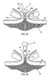
- the fastener 71 of the present invention is positioned in relation to the driving end of an insertion device 74.
- the fastener 71 is mounted onto the insertion device 74 for purposes of deploying the fastener into tissue.
- the fastener 71 is made from bioabsorbable plastic materials such as polyglycolides and comprises two legs 77a, 77b cannulated to receive the insertion needles 79a, 79b of the insertion device 74.
- the insertion device 74 is shown aligned for insertion into the fastener 71, while FIG. 3b shows the two components fully assembled, as would be the case prior to deployment into tissue.
- the needles 79a, 79b of the insertion device 74 when fully inserted in the legs 77a, 77b as shown in FIG. 3b , extend a small distance beyond the distal end of legs 77a, 77b to expose sharp ends 80.
- the sharp ends 80 facilitate penetration into tissue.
- the sharp ends 80 can be, for example, tapered similar to a typical pencil point, as shown in FIG. 3b and other figures. If the sharp ends 80 are tapered, each of them has a centered point, as would a sharpened pencil.
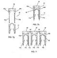
- the sharp ends 80 instead can be, for example, beveled as shown in FIGS. 7g-7i .
- Each leg 77a or 77b of the fastener 71 has at least one barb 83 oriented to resist retraction of the fastener 71 after deployment into tissue.
- the two legs 77a, 77b are connected at the proximal end by a flexible bridge 86.
- FIG. 4a shows the skin 53 being pulled upward by tissue manipulators 91a, 91b while being urged toward the line of apposition 65 by arms 94a, 94b.
- tissue manipulators 91a, 91 b as shown in FIG. 4b and urging by arms 94a, 94b causes the surfaces 68a, 68b of the dermal layer to move from a generally vertical orientation facing each other, to a generally horizontal one facing upward pulling it away from the subdermal tissue and exposing the underside of the dermal layer.
- the insertion device 74 carrying the fastener 71 is shown in the correct orientation prior to inserting the fastener 71 into the tissue.
- FIG. 5a shows the insertion device 74 with fastener 71 after insertion showing the entry point for the legs 77a, 77b into the under side of the dermal layer 59.
- the displacement 97 indicated for leg 77b (and similar for leg 77a) is the distance along the underside of the dermal layer 59 from the cut surface 68b to the insertion point for leg 77b. This displacement 97 of the insertion point is approximately half the length of the bridge 86 where it connects the two legs 77a and 77b.
- this insertion technique allows the barbs 83 to engage the tissue at a depth sufficiently far from the surfaces 68a, 68b so that the bridge 86 can provide a tension holding the tissues together after the insertion device 74 is removed from the fastener 71 as shown in FIG. 5b .
- FIG. 6 shows the tissues of FIG. 5b after the tissue manipulators 91a, 91b and arms 94a, 94b have been removed.
- the flexible bridge 86 bends easily and allows the legs 77a, 77b to spread angularly after the insertion device 74 is removed. A small amount of curvature may remain in the bridge 86, as it is desirable that the tissue be slightly everted where it meets along the line of apposition 65.
- FIGS. 7a through 7e show alternate embodiments of the fastener 71 of the present invention differing principally in the position and number of barbs 83.
- the barbs may further lie in any plane that passes through the axis of the leg, either to facilitate manufacturing (e.g. using injection molding tooling) or to enhance the fastener's retention strength in tissue. However, it is desirable that no barb should be placed such that its pointed element, once the fastener is in place, is directed upwards towards the skin surface 53.
- the fastener in FIG. 7b adds axially directed barbs 98 at the top of each leg that can supplement the retention strength of the other barbs 83 when they are engaged as shown in FIG. 6b .
- fasteners individually, it will be understood that they may be placed in an assembly containing a plurality of fasteners held in relation to one another by a cartridge means or molded in such an assembly with inter connecting frangible plastic components 99, as shown in FIG. 7f . While the inter-connecting components 99 are shown for only one of the alternate embodiments it will be understood that components 99 can be added to other embodiments of FIGS. 7a to 7e .
- the legs 77a, 77b may be oriented in the open position similar to that shown in FIG. 7e with the bridge 86 straightened and subsequently bent to the configuration as shown in FIG. 7a prior to deployment.
- fasteners 71 can be made using a manufacturing process known as insert molding, as shown in FIGS. 7g through 7i .
- insert molding a manufacturing process known as insert molding
- the insertion device 74' is fabricated prior to molding fastener 71.
- Needles 79'a and 79'b are installed in cylindrical shoulders 90a and 90b respectively which are part of yoke 92.
- Insertion device 74' is inserted into a molding cavity in an injection molding process, and the bioabsorbable polymer is injected around it to form fastener 71.
- FIG. 7h shows the combination of insertion device 79' and fastener 71 as molded by this process.
- FIG. 7i shows how the insert molding process described above can be used in a multicavity tool to yield multiple fasteners each connected to another by frangible components 99'.
- FIG. 8 shows compressing forceps 101 that facilitate insertion of the bioabsorbable fastener of the present invention.
- the compressing forceps 101 have at the distal ends of each arm 103a, 103b, half-cylinder components 106a, 106b with features 109a, 109b (indentations or slots) at the top of the half-cylinder components 106a, 106b into which tissue manipulators 91a, 91b can be positioned.
- the user places the compressing forceps 101 so that each cylindrical component 106a, 106b presses against the skin 53 on either side of the line of apposition 65 with the axes of the cylinders parallel to incision or wound.
- Tissue manipulators 91a, 91b are used to pinch each side of the tissue to be apposed and pull it upwards indexing the tips of the manipulators in the features 109a, 109b at the top of the cylindrical component.
- the compressing forceps 101 are then squeezed until stopping elements 112a, 112b in the forceps meet to restrict further compression.
- the stopping elements 112a, 112b are designed to allow the tissues to be compressed leaving a predetermined distance of 4 - 8 mm separating the inner surfaces of the cylindrical components (dimension A in FIG. 8 ).
- This configuration assures that the cut surfaces 68a, 68b of the dermal layer are displaced away from the insertion device exposing the underside of the dermal layer and orienting it upwards to accept the fastener from above.
- the user deploys the fastener using the insertion device by penetrating the compressed dermal tissue between the two cylindrical components 106a, 106b.
- the compressing forceps 101 may also have indexing means to align an insertion device (not shown) so that it penetrates the underside of the dermal tissue equally spaced between the cylindrical components 106a, 106b.
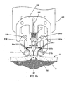
- FIGS. 9a - 9d show an insertion mechanism 200 which provides a means for deploying the fastener 71 from above the skin 53.
- An alternate embodiment of the fastener 71, described above in FIG. 7b is depicted being used with the insertion mechanism 200.
- one method uses an insertion mechanism 200 in conjunction with tissue manipulators 91 a, 91b, to provide a means to coordinate the relative positions of the driving head of the insertion device 74, the tissue compressing arms 203a, 203b and the dermal layer.
- the tissue manipulators 91a, 91b are manually used to pinch the epidermis 56 and pull upwards on the two sides of the incision.
- the distal ends of the tissue manipulators 91a, 91b are then positioned in index cavities 206a, 206b which positions the cut surfaces 68a, 68b of the dermal layer away for the point of penetration on either side of the line of apposition 65.
- the tissue compressing arms 203a, 203b are movably attached to the insertion mechanism 200 as for example, with pivoting elements 209a, 209b.
- the tissue compressing arms 203a, 203b located on either side of the insertion mechanism 200, move in unison when the user presses an actuating lever (not shown).
- the insertion mechanism 200 further comprises an actuation arm 216 attached to the insertion device 74 which allows only vertical translation synchronized to deploy the insertion device 74 carrying one of the fasteners 71 after the tissue is compressed.
- This vertical translation may be driven by electromotive, spring, or manual force through coupling arms, or other means known in the art for driving staples.
- the final downward position may be constrained by a mechanical stop (not shown) adjusted to deploy the fastener to a desired depth in the tissue.
- the final downward position is determined by a limiting spring 219, which is chosen to compress significantly only when a force comparable to the maximum force to be applied to the insertion device to seat the fastener fully within the everted tissue is applied. If the motive force for the actuation arm 216 is manual force the limiting spring 219 can provide force feedback to the user without appreciably advancing the fastener further into the tissue. This adds a degree of compliance to the mechanism making the exact vertical position of the surfaces 68a, 68b of the dermis less critical than with a rigid mechanism. In addition, the likelihood of tissue tearing as a result of excessive force applied to the actuation arm 216 is reduced so long as the user remains sensitive to the maximum appropriate force to be applied.
- tissue manipulators 91a, 91b have pinched the epidermis 56 on either side of the wound to be apposed and the insertion mechanism 200 has been brought into place.
- the tissue manipulators 91a, 91b have been located to index cavities 206a, 206b provided on the insertion mechanism for this purpose.
- a fastener 71 has been mounted on the insertion device 74, which is in turn mounted to the actuation arm 216 by means of a shaft 222 that allows only vertical translation.
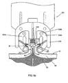
- the actuating arm 216 of the mechanism has started to descend, forcing tissue compressing arms 203a, 203b against the edges of epidermis 56 held by the tissue manipulators 91a, 91b. Movement of the tissue compressing arms 203a, 203b is limited by the engagement of the actuating arm 216 such that the cylindrical elements 213a, 213b remain separated a predetermined distance between 4mm and 8mm as indicated by dimension "B".
- the fastener 71 is shown ready to descend with the insertion device 74 driven by the actuation arm 216 towards the underside of the dermal layer of the wound.
- the actuating arm 216 of the insertion mechanism 200 has descended further than in FIG. 9b , maintaining the position of the tissue compressing arms 203a, 203b while inserting the fastener 71 into the tissue with the aid of the sharp ends 80 of the insertion device 74.
- the sharp ends 80 can be tapered as shown in FIG. 3b or beveled as shown in FIGS. 7g-7i , to give just two examples of the possible shapes of the sharp ends 80.
- the limiting spring 219 is compressing, which builds up the force feedback on the user who is providing the motivating force on the actuation arm without appreciably advancing the fastener further into the tissue.
- the fastener 71 is desireably inserted at a point that is displaced from the edge of the cut surfaces 68a, 68b by a distance C that is approximately half the length of the bridge 86 of the fastener 71.
- the actuation arm 216 is shown in a partially retracted position leaving the fastener 71 in place in the dermal layer 59.
- Remaining steps include the further retraction of the actuation arm 216, allowing the tissue compressing arms 203a, 203b to reopen, and the insertion mechanism 200 to be withdrawn while the tissue manipulators 91a, 91b momentarily retain the edges of the epidermis 56.
- the user brings the tissue manipulators 91a and 91b together along the line of apposition thereby pulling the two sides of the dermal layer 59 until the surfaces 68a, 68b of the dermal layer touch one another.
- the bridge straightens and comes into tension at the point where the surfaces 68a, 68b touch.
- FIG. 10 shows compressing forceps 301 having tissue contacting members 306a and 306b that are referred to herein as presser feet and which are shown in FIG. 10 in cross section.
- the presser feet 306a and 306b have a lower vertical profile than the half-cylinder components 106a and 106b of compressing forceps 101 of FIG. 8 , with that height or profile of the presser feet 306a, 306b shown in FIG. 10 as "d" where "d" can be, for example, about 1.0 mm.
- This lower profile allows the cut surfaces 68a and 68b of the skin tissue to be everted and reflected over the presser feet 306a and 306b at a more acute angle than achievable with the arrangements of FIGS.
- the presser feet 306a and 306b can include surface features 309a and 309b for engaging the ends of tissue manipulators 391a and 391b.
- the surface features 309a and 309b can be notches or ridges, for example. By engaging the ends of tissue manipulators 391a and 391b, the surface features 309a and 309b help to stabilize the manipulators 391a and 391b in a fixed position once the cut surfaces 68a and 68b of the skin tissue have been elevated and reflected over the presser feet 306a and 306b to the extent desired.
- the presser feet 306a and 306b can be made of any sterilizable metal (such as stainless steel), sterilizable or single use plastic, or other material suitable for use in surgical instruments. They can be formed integrally with the arms 303a and 303b of the compressing forceps 301, or they can be attached by means of weld joints, screws, adhesive, and/or snap-fitting connecting members.
- the presser feet 306a and 306b can be brought into apposition by squeezing the compressing forceps 301 until the stopping elements 312a and 312b make contact. As shown in FIG. 10 , a predetermined gap A' remains between the opposing presser feet 306a and 306b when stopping element 312a makes contact with stopping element 312b. This gap A' is designed to bring the cut surfaces 68a and 68b together to the extent necessary to align fastener leg 77a with cut surface 68a, and fastener leg 77b with cut surface 68b, as shown in FIG. 12a .
- Gap A' is larger than fastener width B' by about 1.0mm to ensure that fastener legs 77a and 77b reliably penetrate through the dermis 59 and partially into the subcutaneous tissue 62, as shown in FIG. 12b .
- the gap A' can be in the range of about 4.05mm to about 4.15mm.
- the tissue is then ready to receive an insertion device 74 having a mounted fastener 71.
- the insertion device can be inserted into the tissue in a number of ways. For example, an operator can grasp insertion device 74 manually with thumb and index finger and advance it generally perpendicular to the plane or surface of the tissue as shown in FIG. 12a . After depositing the fastener 71 into cut surfaces 68a and 68b, the operator can then withdraw the insertion device 74, as shown in FIG. 12c .
- FIG. 11 is a perspective view of a hand-held insertion mechanism 400 which can hold and deploy the fastener 71 from above the plane of the tissue 453 (e.g., the skin of a human or other mammal) having the cut or incision.
- the insertion mechanism 400 is held in a position to place its insertion device 74 generally perpendicular to the plane or surface of the tissue having the cut or incision, as shown in FIG. 12a .
- the insertion mechanism 400 can have loaded into it and held internally one or more of the fasteners 71.
- the insertion mechanism 400 comprises a pair of opposing presser feet 406a and 406b attached to the insertion mechanism 400 via arms 403a and 403b, respectively. Arms 403a and 403b are spaced apart by gap 412 which is chosen to provide the correct gap A' between the opposing presser feet 406a and 406b. Gap 412 may be fixed by the mechanical assembly of the insertion mechanism 400 or in another example gap 412 can be adjustable by a screw or other means know in the art.
- At least one of the presser feet 406a and 406b can have an angular or curved shape in the horizontal plane, such that the distal ends of presser feet 406a and 406b define a wider lead-in area that becomes progressively narrower from front to back, as shown in FIG. 11 .
- the lead-in area reaches a minimum width which defines gap A' directly beneath the insertion device 74.
- tissue manipulators 491a and 491b to raise cut surfaces 68a and 68b.
- the operator can then slide insertion mechanism 400 longitudinally along the cut, trapping and compressing the cut surfaces 68a and 68b between the fixed presser feet 406a and 406b, as shown in FIG. 11 .
- arms 403a and 403b of the insertion mechanism 400 can move in response to handles 410a and 410b to move presser feet 406a and 406b laterally into and out of the operative field.
- the insertion mechanism 400 can be placed directly over the planned insertion site with reference to alignment mark 420, and the operator can move handles 410a and 410b through a first distance to compress presser feet 406a and 406b and align the tissue segments.
- an operator can manually compress handles 410a and 410b through a second distance, causing downward movement of the insertion device 74.
- the insertion device 74 As the insertion device 74 is made to move downward toward the tissue, it exits fastener cartridge 416 and penetrates the cut surfaces 68a and 68b, depositing fastener 71 (not shown).
- the handles 410a and 410b can be spring-loaded, so that upon release of the handles, the insertion device 74 can retract into fastener cartridge 416, leaving the embedded fastener 71 behind as shown in FIG. 12c .
- the insertion mechanism 400 also can be configured to accept a plurality of the fasteners 71 held in fastener cartridge 416.
- each fastener 71 is factory installed onto a disposable insertion device 74 and the plurality of these assemblies is held in fastener cartridge 416.
- the assemblies of fastener 71 and insertion device 74 can be fabricated from separate components, or by an insert molding process as described previously with reference to FIGS. 7g, 7h, and 7i .
- the insertion mechanism 400 operates on the insertion devices one at a time to deploy the tissue fasteners 71 into the tissue and to store each insertion device 74'after deploying its preloaded tissue fastener 71.
- insertion mechanism 400 has one insertion device 74 and a plurality of fasteners 71 are positioned within fastener cartridge 416.
- the plurality of fasteners 71 may be individually placed into fastener cartridge or inserted as a molded assembly with inter-connecting frangible components 99, as shown in FIG. 7f .
- the frangible components 99 can be formed with and made out of the same bioabsorbable material used to form the fasteners 71.
- This assembly of breakaway fasteners provides ease of loading the fasteners 71 into the cartridge 416 and also provides controlled positioning of the fasteners 71 to facilitate the mechanical loading of the fastener onto the insertion device 74 for deployment.
- FIG. 7f depicts the frangible components 99 interconnecting the bridge sections 86 of the fasteners 71, the breakaway connecting components 99 can instead, or additionally, releasably connect together one or more other sections of adjacent fasteners 71.
- FIG. 12a - 12d The method of deploying fastener 71 into tissue is further explained in FIG. 12a - 12d .
- the sequence of steps is similar for an operator manually inserting individual insertion devices 74 with the aid of compressing forceps 301 or using the hand-held insertion mechanism 400.
- the low profile of presser feet 306a and 306b (or 406a and 406b), allows the cut surfaces 68a and 68b to be raised and retracted at an acute angle with respect to the plane of tissue 53.
- FIG. 12b the acute angle of reflection of the cut surfaces 68a and 68b allows the needles 79a and 79b of insertion device 74 to enter and exit the dermis 59.
- FIG. 12a the low profile of presser feet 306a and 306b (or 406a and 406b)
- the fastener 71 is left behind in the tissue by virtue of the engagement of barbs 83 of legs 77a and 77b into the dermis 59.
- FIG. 12d upon release of the cut surfaces 68a and 68b and removal of the tissue manipulators 391a and 391b (or 491a and 491b), as well as presser feet 306a and 306b (or 406a and 406b), the cut surfaces 68a and 68b relax into anatomical apposition with one another.
- the elasticity of the tissue causes the two cut surfaces 68a and 68b to exert a distracting force against the embedded fastener 71, causing its legs 77a and 77b to spread apart, a process facilitated by the flexible bridge 86.
- the curvature of the flexible bridge 86 is reduced, and the distracting force places the bridge 86 in tension thereby aligning and holding legs 77a and 77b from further separation.
- the tensile strength of legs 77a, 77b, and bridge 86 acting on the engagement of barbs 83 with the dermis 59 holds the tissue in apposition. As shown in FIG.
- incorporating additional barbs 98 can provide support for apposing the tissue to reduce the likelihood of the tissue receding to expose the mid-section of bridge 86 under conditions of increased distraction force. These conditions can occur, for example in skin that overlies a joint, or that is otherwise subject to frequent stretching (such as facial skin).
- An advantage of the fastener 71 is that it functions by placing the legs 77a and 77b in tension with bridge 86.
- Various known staples whether metal or plastic, hold the tissue in apposition by structural strength, compressive strength, or resistance to deformation.
- a property of plastics, such as bioabsorbable materials used in the present invention, is to be significantly stronger in tensile strength than in deformation resistance strength.
- the fastener 71 can be made smaller and less irritating to tissue than known fasteners.
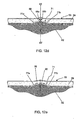
- FIG. 13a A perspective view of an embodiment of fastener 71 is shown in FIG. 13a .
- a top view of fastener 71 is shown in FIG. 13b .
- the distance 85 between lumen 84a of leg 77a and lumen 84b of leg 77b is approximately 2.75mm.
- FIG. 13c Shown in FIG. 13c is a front view of fastener 71 through section A-A of FIG. 13b .
- a partial cutaway view of leg 77b is shown, demonstrating the dimensional relationships between leg 77b, lumen 84b and barb 83.
- Barb 83 for example, can form an angle 72 of approximately 30 degrees with respect to the long axis of leg 77b.
- the effective sharpness of barb 83 can be given by angle 73, which in this case is approximately 25 degrees.
- the perpendicular distance 70 of the tip of barb 83 from the surface of leg 77b in this embodiment is approximately 0.6 mm.
- the amount by which the distal portion 78b of leg 77b tapers inwardly can be determined by angle 75, which in this embodiment is approximately 15 degrees.
- the overall width 76 of leg 77b is approximately 0.8mm
- the diameter 81 of lumen 84b is approximately 0.3mm
- the radial thickness of the wall of leg 77b tapers from approximately 0.25 mm to approximately 0.075 mm at its tip 78.
- FIG. 13d is a side view of fastener 71, through section B-B of FIG. 13c .
- the overall length 87 of legs 77a and 77b is approximately 5.25mm.
- the cross-sectional rectangular shape of bridge 86 of this embodiment is also apparent in this view, a shape that contributes to the lateral flexibility of the bridge.
- the bridge 86 of FIG. 13d has a vertical thickness 88 of approximately 0.25mm and a transverse thickness 89 of approximately 0.7mm.
- Embodiments of fasteners according to the invention can be manufactured from one or more bioabsorbable materials, such as copolymers of L-Lactide or D,L-Lactide, and Glycolide. Any suitable bioabsorbable material(s) can be used to form the fastener 71, as long as the material(s) can be formed into the fastener 71 and perform as disclosed herein.
- bioabsorbable and bioabsorbable material as used herein are intended to include any suitable material(s) for fasteners according to the invention that hold their shape and are stable outside of the body but that degrade, resorb, absorb, erode, and/or otherwise breakdown within the body of a patient over time and are eliminated by the body's normal functions.
- a fastener made of a poly(lactic-glycolic) acid (“PLGA”) copolymer can have a ratio of L-lactide to Glycolide of from about 10:90 to about 95:5 by weight, such as for example 80:20, 82:18, or 85:15.
- PLGA poly(lactic-glycolic) acid
- the bioabsorbable material used for the fastener 71 is a lactide/glycolide copolymer (such as, for example, poly-DL-Lactide-co-Glycolide or "PDLGA") where the ratio is never less than at least 10% of one element and, in a more specific embodiment, is in a range of 60%-70% lactide.
- a lactide/glycolide copolymer such as, for example, poly-DL-Lactide-co-Glycolide or "PDLGA”
- bioabsorbable materials that could be used to form a fastener according to the invention include poly(d1-lactide), poly(1-lactide), polyglycolide, poly(dioxanone), poly(glycolide-co-trimethylene carbonate), poly(1-lactide-co-glycolide), poly(d1-lactide-co-glycolide), poly(1-lactide-co-d1-lactide), poly(glycolide-co-trimethylene carbonate-co-dioxanone), caprolactone, ploydioxane, and/or copolymers of L-Lactide or D,L-Lactide, and Glycolide.
- the material used for the fastener 71 could include compositions with naturally occurring biopolymers such as collagen and elastin, or stainless steel, metal, nylon or any other biocompatible materials in the case of a non-absorbable fastener, or even various combinations of such materials depending upon the desired application and performance of the fastener 71.
- a bioabsorbable fastener is formed of a polymer, or a formulation of polymers, which provides a tensile breaking strength from leg 77a to leg 77b across bridge 86 of about 3.5 lbs. upon initial deployment into a patient and maintains that breaking strength at or above about 2 lbs. for a minimum of about 5 days.
- a fastener made of PLGA having a ratio of L-lactide to Glycolide of about 82:18 and having a bridge of a rectangular cross-section of about 0.25 mm high and about 0.8 mm wide can have such force-withstanding properties.
- each of the fasteners 71 will be formed in such a way and of one or more bioabsorbable materials suitable to allow the fastener 71 to maintain its structural integrity within the body of the patient for about 14 days or for a minimum of about 5 days.
- the specific time it takes for any particular fastener to be bioabsorbed in any particular application within the body of a patient typically will vary and is a function of the bioabsorbable material(s) used to form the fastener, the fastener's precise shape, the area within the body of the patient where the fastener is deployed, and the patient himself or herself.
Claims (7)
- Ein Befestigungssystem zum Einsatz beim Aneinanderlegen von zwei Seiten einer Inzision oder Wunde in einer Oberfläche von Hautgewebe durch Zusammenhalten der Seiten unter Zugspannung, welches Folgendes umfasst:ein Befestigungselement (71), welches aus Folgendem besteht: i. ein Brückenteil (86), welches ein erstes und ein zweites Stück umfasst, ii. ein erstes Beinteilstück (77a), welches mit dem Brückenteil (86) fest verbunden ist und sich aus dem ersten Teilbereich des Brückenteils (86) erstreckt, wobei das erste Beinteilstück (77a) ein erstes Lumen (84a) aufweist, das dort hindurch in einer Weise verläuft, dass das erste Beinteilstück (77a) kanüliert ist, und iii. ein zweites Beinteilstück (77b), welches mit dem Brückenteil (86) fest verbunden ist und sich aus dem zweiten Teilbereich des Brückenteils (86) erstreckt, wobei das zweite Beinteilstück ein zweites Lumen (84b) aufweist, das dort hindurch in einer Weise verläuft, dass das zweite Beinteilstück (77b) kanüliert ist, ein distaler Teil eines jeden der ersten und zweiten Beinteilstücke (77a, 77b) läuft konisch zu, jedes der ersten und zweiten Beinteilstücke (77a, 77b) umfasst mindestens einen Widerhaken (83), das Brückenteil (86) ist ausreichend nachgiebig, um es den ersten und zweiten Beinteilstücken (77a, 77b) zu ermöglichen, sich winkelförmig auseinander zu spreizen, wenn sie vollständig unter der Oberfläche des Hautgewebes implantiert sind, dergestalt, dass die Seiten der Inzision oder Wunde unter Zugspannungskräften zwischen den Widerhaken zusammengehalten werden, das Brückenteil (86) und die ersten und zweiten Beinteilstücke (77a, 77b) sind aus einem einzigen Materialstück gebildet; undeine Einbringungsvorrichtung (74), dazu gestaltet um das Befestigungselement (71) von oben und in einer im Allgemeinen senkrechten Ausrichtung, bezogen auf die Oberfläche des Hautgewebes, in das Hautgewebe einzubringen, dergestalt dass das eingebrachte Befestigungselement (71) so angeordnet wird, dass es vollständig unter der Oberfläche des Hautgewebes eingesetzt ist, um die Seiten der Inzision oder Wunde durch Zugspannung zusammen zu halten, die Einbringungsvorrichtung (74), welche eine erste Nadel (79a) umfasst, die dafür gestaltet ist, um durch das erste Lumen (84a) des kanülierten ersten Beinteilstücks (77a) hindurch zu führen, und eine zweite Nadel (79b) umfasst, die dafür gestaltet ist, um durch das zweite Lumen (84b) des kanülierten zweiten Beinteilstücks (77b) hindurch zu führen, die ersten und zweiten Nadeln (79a, 79b) stehen im Wesentlichen parallel zueinander, jede der ersten und zweiten Nadeln (79a, 79b) weist ein spitzes Ende (80) auf, welches freigelegt wird, wenn das Befestigungselement (71) in der Einbringungsvorrichtung (74) vollständig eingesetzt ist, die spitzen Enden (80) dienen zur Durchdringung in das Hautgewebe,dadurch gekennzeichnet, dass jeder der Widerhaken (83) ein spitz zulaufendes Element aufweist und positioniert wird, um so ausgerichtet zu werden, dass sein spitz zulaufendes Element von der Oberfläche des Hautgewebes weggeführt wird, und dergestalt, dass der Widerhaken (83) einer Verlagerung des Befestigungselements (71) widersteht, nachdem das Befestigungselement (71) in das Hautgewebe und unter die Oberfläche des Hautgewebes eingebracht wurde.
- Das System von Anspruch 1, wobei das Befestigungselement (71) in die Einbringungsvorrichtung (74) voreingesetzt ist.
- Das System von Anspruch 1, wobei das einzelne Materialstück im Körper abbaubar ist.
- Das System von Anspruch 3, wobei das im Körper abbaubare Material ein Copolymer umfasst.
- Das System von Anspruch 3, wobei das im Körper abbaubare Material eine Mischung von Polymeren umfasst.
- Das System von Anspruch 1, wobei der Brückenteil (86) einen zerbrechlichen Verbinder (99) zum lösbaren Verbinden des Brückenteils (86) mit einem anderen Befestigungselement (71) umfasst.
- Das System von Anspruch 1, wobei bei in die Einbringungsvorrichtung (74) eingesetztem Befestigungselement (71) der mindestens eine Widerhaken (83) des ersten Beinteilstücks (77a) des Befestigungselements (71) dem mindestens einen Widerhaken (83) des zweiten Beinteilstücks (77b) des Befestigungselements (71) gegenüberliegt.
Priority Applications (1)
| Application Number | Priority Date | Filing Date | Title |
|---|---|---|---|
| EP15167751.5A EP2987456A1 (de) | 2006-07-01 | 2007-06-29 | Chirurgische befestigungen und zugehörige einsetzvorrichtungen, und -mechanismen |
Applications Claiming Priority (2)
| Application Number | Priority Date | Filing Date | Title |
|---|---|---|---|
| US81785806P | 2006-07-01 | 2006-07-01 | |
| PCT/US2007/015418 WO2008005465A2 (en) | 2006-07-01 | 2007-06-29 | Tissue fasteners and related insertion devices, mechanisms, and methods |
Related Child Applications (1)
| Application Number | Title | Priority Date | Filing Date |
|---|---|---|---|
| EP15167751.5A Division EP2987456A1 (de) | 2006-07-01 | 2007-06-29 | Chirurgische befestigungen und zugehörige einsetzvorrichtungen, und -mechanismen |
Publications (3)
| Publication Number | Publication Date |
|---|---|
| EP2034904A2 EP2034904A2 (de) | 2009-03-18 |
| EP2034904A4 EP2034904A4 (de) | 2013-01-23 |
| EP2034904B1 true EP2034904B1 (de) | 2015-06-03 |
Family
ID=38895203
Family Applications (2)
| Application Number | Title | Priority Date | Filing Date |
|---|---|---|---|
| EP07810174.8A Not-in-force EP2034904B1 (de) | 2006-07-01 | 2007-06-29 | Gewebebefestigungselemente und relevante einführvorrichtungen |
| EP15167751.5A Withdrawn EP2987456A1 (de) | 2006-07-01 | 2007-06-29 | Chirurgische befestigungen und zugehörige einsetzvorrichtungen, und -mechanismen |
Family Applications After (1)
| Application Number | Title | Priority Date | Filing Date |
|---|---|---|---|
| EP15167751.5A Withdrawn EP2987456A1 (de) | 2006-07-01 | 2007-06-29 | Chirurgische befestigungen und zugehörige einsetzvorrichtungen, und -mechanismen |
Country Status (8)
| Country | Link |
|---|---|
| US (3) | US8506591B2 (de) |
| EP (2) | EP2034904B1 (de) |
| JP (1) | JP5067976B2 (de) |
| CN (1) | CN101511278B (de) |
| AU (1) | AU2007269655B2 (de) |
| CA (1) | CA2655197C (de) |
| HK (1) | HK1123961A1 (de) |
| WO (1) | WO2008005465A2 (de) |
Families Citing this family (33)
| Publication number | Priority date | Publication date | Assignee | Title |
|---|---|---|---|---|
| US20120145765A1 (en) | 2002-06-25 | 2012-06-14 | Peterson James A | Mechanical method and apparatus for bilateral tissue fastening |
| EP2015681B1 (de) | 2006-05-03 | 2018-03-28 | Datascope Corp. | Gewebeverschlussvorrichtung |
| EP2034904B1 (de) | 2006-07-01 | 2015-06-03 | Opus KSD, Inc. | Gewebebefestigungselemente und relevante einführvorrichtungen |
| US20100082046A1 (en) * | 2007-07-18 | 2010-04-01 | Harris Jason L | Device For Deploying A Fastener For Use in a Gastric Volume Reduction Procedure |
| US8602286B2 (en) | 2009-01-26 | 2013-12-10 | Ethicon Endo-Surgery, Inc. | Apparatus for feeding staples in a low profile surgical stapler |
| US9713468B2 (en) | 2009-01-26 | 2017-07-25 | Ethicon Endo-Surgery, Inc. | Surgical stapler for applying a large staple through a small delivery port and a method of using the stapler to secure a tissue fold |
| US8439244B2 (en) | 2010-01-20 | 2013-05-14 | Ethicon Endo-Surgery, Inc. | Surgical stapler fastening device with movable anvil |
| US20100187285A1 (en) * | 2009-01-26 | 2010-07-29 | Harris Jason L | Surgical stapler for applying a large staple though a small delivery port and a method of using the stapler to secure a tissue fold |
| US8801732B2 (en) * | 2009-01-26 | 2014-08-12 | Ethicon Endo-Surgery, Inc. | Surgical stapler to secure a tissue fold |
| US8469252B2 (en) | 2009-01-26 | 2013-06-25 | Ethicon Endo-Surgery, Inc. | Surgical stapler fastening device with adjustable anvil |
| US9713471B2 (en) | 2009-01-26 | 2017-07-25 | Ethicon Endo-Surgery, Inc. | Surgical device with tandem fasteners |
| US20100191262A1 (en) * | 2009-01-26 | 2010-07-29 | Harris Jason L | Surgical stapler for applying a large staple through small delivery port and a method of using the stapler to secure a tissue fold |
| US8453905B2 (en) | 2009-01-26 | 2013-06-04 | Ethicon Endo-Surgery, Inc. | Surgical fastener for applying a large staple through a small delivery port |
| JP5465787B2 (ja) * | 2009-11-19 | 2014-04-09 | ディージーアイメド オーソ, インコーポレイテッド | 髄内システムおよび方法 |
| WO2012135530A1 (en) | 2011-03-29 | 2012-10-04 | Ocunetics, Inc. | Fasteners, deployment systems, and methods for ophthalmic tissue closure and fixation of ophthalmic prostheses and other uses |
| US9974928B2 (en) * | 2011-05-10 | 2018-05-22 | Safesharp Technologies Corporation | Apparatus for securing a medical clamp to a patient |
| EP2787898B1 (de) | 2011-12-08 | 2019-05-01 | O3 Optix LLC | Befestigungselemente, einsatzsysteme und verfahren für augengewebeverschlüsse und zur fixierung von augenprothesen und für andere anwendungen |
| US8992547B2 (en) | 2012-03-21 | 2015-03-31 | Ethicon Endo-Surgery, Inc. | Methods and devices for creating tissue plications |
| US9232943B2 (en) | 2013-01-31 | 2016-01-12 | Opus Ksd Inc. | Delivering bioabsorbable fasteners |
| US20140276968A1 (en) * | 2013-03-14 | 2014-09-18 | Ethicon, Inc. | Applicator systems for surgical fasteners |
| EP3013395B1 (de) | 2013-06-28 | 2019-10-02 | Duc Hong Le | Katheterverankerungsvorrichtung und verfahren |
| US9427232B2 (en) | 2013-11-08 | 2016-08-30 | C.R. Bard, Inc. | Surgical fastener |
| US10052105B2 (en) * | 2013-11-18 | 2018-08-21 | Ethicon, Inc. | Recessed surgical fastening devices |
| US10485545B2 (en) | 2013-11-19 | 2019-11-26 | Datascope Corp. | Fastener applicator with interlock |
| US9844377B2 (en) | 2014-04-25 | 2017-12-19 | Incisive Surgical, Inc. | Method and apparatus for wound closure with sequential tissue positioning and retention |
| CN105310735B (zh) * | 2014-11-27 | 2017-05-10 | 中国人民解放军第二军医大学 | 组织闭合钉 |
| USD752219S1 (en) * | 2015-01-02 | 2016-03-22 | Incisive Surgical, Inc. | Tissue fastening instrument |
| US10786248B2 (en) | 2016-01-11 | 2020-09-29 | Ethicon. Inc. | Intra dermal tissue fixation device |
| JP7348199B2 (ja) | 2018-03-28 | 2023-09-20 | データスコープ コーポレイション | 心耳除外のためのデバイス |
| US20190374220A1 (en) * | 2018-04-05 | 2019-12-12 | Quickstitch Surgical, Inc. | Apparatus and methods for approximating and securing tissue |
| CA3235943A1 (en) * | 2021-11-01 | 2023-05-04 | Felmont F. Eaves | Applicator tool capable of use with force modulating tissue bridge, and associated systems, methods and kits |
| CN113995457B (zh) * | 2021-12-10 | 2024-01-16 | 苏州法兰克曼医疗器械有限公司 | 一种具有高稳定性的电动皮肤吻合器 |
| WO2023172446A1 (en) | 2022-03-11 | 2023-09-14 | Opus Ksd Inc. | Devices for deploying tissue fasteners |
Family Cites Families (81)
| Publication number | Priority date | Publication date | Assignee | Title |
|---|---|---|---|---|
| US2206460A (en) * | 1936-03-14 | 1940-07-02 | Hansen Mfg Co A L | Tacking and stapling machine |
| US2457362A (en) * | 1944-12-22 | 1948-12-28 | Premier Thread Company | Apparatus for cooling sewing machine needles |
| US3716058A (en) | 1970-07-17 | 1973-02-13 | Atlanta Res Inst | Barbed suture |
| US3875648A (en) | 1973-04-04 | 1975-04-08 | Dennison Mfg Co | Fastener attachment apparatus and method |
| US4179063A (en) | 1976-03-29 | 1979-12-18 | Dennison Manufacturing Company | Feed and severing apparatus |
| US4410125A (en) * | 1981-10-02 | 1983-10-18 | United States Surgical Corporation | Surgical stapler apparatus with curved staple pusher |
| US4627437A (en) | 1983-06-20 | 1986-12-09 | Ethicon, Inc. | Method of applying a fastener to tissue with a pair of hollow needles |
| EP0185026A1 (de) * | 1984-05-07 | 1986-06-25 | PUCHY, David Peter William | Vorrichtung zum anbringen von wundklammern mit einstellbarer weite |
| US4736746A (en) | 1985-04-11 | 1988-04-12 | Dennison Manufacturing Company | Method of fastening tissues |
| US4669473A (en) | 1985-09-06 | 1987-06-02 | Acufex Microsurgical, Inc. | Surgical fastener |
| IT1203985B (it) * | 1987-04-30 | 1989-02-23 | Rockwell Rimoldi Spa | Macchina per cucire modulare, predisposta per il comando di dispositivi ausiliari |
| US4994073A (en) | 1989-02-22 | 1991-02-19 | United States Surgical Corp. | Skin fastener |
| US5089009A (en) | 1989-06-27 | 1992-02-18 | United States Surgical Corporation | Inwardly biased skin fastener |
| US5038931A (en) | 1989-05-04 | 1991-08-13 | Kunreuther Steven J | Assembly of attachments and device for attaching same |
| CA2049123C (en) | 1990-09-13 | 2002-01-15 | David T. Green | Apparatus and method for subcuticular stapling of body tissue |
| US5269783A (en) | 1991-05-13 | 1993-12-14 | United States Surgical Corporation | Device and method for repairing torn tissue |
| CA2437773C (en) | 1992-09-21 | 2005-02-22 | United States Surgical Corporation | Device for applying a meniscal staple |
| CH686681A5 (de) * | 1993-03-31 | 1996-05-31 | Fritz Gegauf Ag Bernina N Hmas | Naehfuss. |
| US5342376A (en) | 1993-05-03 | 1994-08-30 | Dermagraphics, Inc. | Inserting device for a barbed tissue connector |
| US5584859A (en) | 1993-10-12 | 1996-12-17 | Brotz; Gregory R. | Suture assembly |
| ZA947935B (en) * | 1993-10-18 | 1995-05-25 | Press Engineering Proprietary | "File fastener" |
| US5466243A (en) | 1994-02-17 | 1995-11-14 | Arthrex, Inc. | Method and apparatus for installing a suture anchor through a hollow cannulated grasper |
| US5618311A (en) | 1994-09-28 | 1997-04-08 | Gryskiewicz; Joseph M. | Surgical subcuticular fastener system |
| US5615816A (en) | 1995-05-08 | 1997-04-01 | Avery Dennison Corporation | Dispensing of attachments |
| US5718359A (en) | 1995-08-14 | 1998-02-17 | United States Of America Surgical Corporation | Surgical stapler with lockout mechanism |
| US5810851A (en) * | 1996-03-05 | 1998-09-22 | Yoon; Inbae | Suture spring device |
| GB2317621B (en) | 1996-09-19 | 1998-08-19 | Dennis Huang | Handy button attaching apparatus |
| US5709708A (en) * | 1997-01-31 | 1998-01-20 | Thal; Raymond | Captured-loop knotless suture anchor assembly |
| US5984949A (en) * | 1997-10-06 | 1999-11-16 | Levin; John M. | Tissue hooks and tools for applying same |
| CA2326125A1 (en) | 1998-04-01 | 1999-10-07 | Bionx Implants Oy | Bioabsorbable surgical fastener for tissue treatment |
| US6200330B1 (en) * | 1998-11-23 | 2001-03-13 | Theodore V. Benderev | Systems for securing sutures, grafts and soft tissue to bone and periosteum |
| US6402759B1 (en) | 1998-12-11 | 2002-06-11 | Biohorizons Implant Systems, Inc. | Surgical fastener driver |
| US6387113B1 (en) * | 1999-02-02 | 2002-05-14 | Biomet, Inc. | Method and apparatus for repairing a torn meniscus |
| US6991643B2 (en) | 2000-12-20 | 2006-01-31 | Usgi Medical Inc. | Multi-barbed device for retaining tissue in apposition and methods of use |
| US6423073B2 (en) * | 1999-07-23 | 2002-07-23 | Ethicon, Inc. | Instrument for inserting graft fixation device |
| US6179840B1 (en) * | 1999-07-23 | 2001-01-30 | Ethicon, Inc. | Graft fixation device and method |
| US6554852B1 (en) * | 1999-08-25 | 2003-04-29 | Michael A. Oberlander | Multi-anchor suture |
| US6231561B1 (en) * | 1999-09-20 | 2001-05-15 | Appriva Medical, Inc. | Method and apparatus for closing a body lumen |
| US6610079B1 (en) | 1999-12-14 | 2003-08-26 | Linvatec Corporation | Fixation system and method |
| CH694357A5 (fr) * | 2000-05-31 | 2004-12-15 | M D Supply S A R L | Ensemble de fixation d'un tissu mou sur un os |
| US6485504B1 (en) * | 2000-06-22 | 2002-11-26 | James A. Magovern | Hard or soft tissue closure |
| US6325007B1 (en) * | 2000-07-17 | 2001-12-04 | Bennie Farmer | Thread guide attachment for sewing machines |
| US6663633B1 (en) | 2000-10-25 | 2003-12-16 | Pierson, Iii Raymond H. | Helical orthopedic fixation and reduction device, insertion system, and associated methods |
| US6733506B1 (en) * | 2000-11-16 | 2004-05-11 | Ethicon, Inc. | Apparatus and method for attaching soft tissue to bone |
| CA2432904C (en) | 2000-12-21 | 2007-09-11 | Nektar Therapeutics | Induced phase transition method for the production of microparticles containing hydrophobic active agents |
| DE10064531C2 (de) | 2000-12-22 | 2002-11-07 | Roland Man Druckmasch | Vorrichtung zum schwebenden Führen von Bahn- oder Bogenmaterial in einer Verarbeitungsmaschine |
| US20020111641A1 (en) | 2001-01-08 | 2002-08-15 | Incisive Surgical, Inc. | Bioabsorbable surgical clip with engageable expansion structure |
| US7033379B2 (en) | 2001-06-08 | 2006-04-25 | Incisive Surgical, Inc. | Suture lock having non-through bore capture zone |
| US7056331B2 (en) | 2001-06-29 | 2006-06-06 | Quill Medical, Inc. | Suture method |
| US20040005937A1 (en) * | 2001-07-02 | 2004-01-08 | Saiz Manuel Munoz | Golf ball |
| WO2003011148A1 (en) | 2001-07-31 | 2003-02-13 | William Bauer | Stapling device for closure of deep tissue |
| US6652563B2 (en) * | 2001-10-02 | 2003-11-25 | Arthrex, Inc. | Suture anchor with internal suture loop |
| US6601748B1 (en) * | 2001-12-15 | 2003-08-05 | Modern Medical Equip. Mfg., Ltd. | Surgical stapler |
| DE60333344D1 (de) * | 2002-02-25 | 2010-08-26 | Teresa T Yeung | Spreizbares befestigungselement mit zusammendrückbaren greifelementen |
| US7077850B2 (en) | 2002-05-01 | 2006-07-18 | Scimed Life Systems, Inc. | Tissue fastening devices and related insertion tools and methods |
| US8105342B2 (en) | 2002-05-08 | 2012-01-31 | Apollo Endosurgery, Inc. | Apparatus for ligating/suturing living tissues and system for resecting/suturing living tissues |
| US7059509B2 (en) * | 2002-05-28 | 2006-06-13 | Phillip Clay Brown | Surgical stapling device |
| US7004950B1 (en) * | 2002-06-21 | 2006-02-28 | Collins James R | Tissue aligning surgical stapler and method of use |
| US8074857B2 (en) * | 2002-06-25 | 2011-12-13 | Incisive Surgical, Inc. | Method and apparatus for tissue fastening with single translating trigger operation |
| US6726705B2 (en) | 2002-06-25 | 2004-04-27 | Incisive Surgical, Inc. | Mechanical method and apparatus for bilateral tissue fastening |
| US20120145765A1 (en) | 2002-06-25 | 2012-06-14 | Peterson James A | Mechanical method and apparatus for bilateral tissue fastening |
| US7112214B2 (en) | 2002-06-25 | 2006-09-26 | Incisive Surgical, Inc. | Dynamic bioabsorbable fastener for use in wound closure |
| US7950559B2 (en) * | 2002-06-25 | 2011-05-31 | Incisive Surgical, Inc. | Mechanical method and apparatus for bilateral tissue fastening |
| US7413570B2 (en) * | 2002-08-21 | 2008-08-19 | Kci Licensing, Inc. | Medical closure screen installation systems and methods |
| US7048171B2 (en) * | 2002-08-29 | 2006-05-23 | Dale H. Kosted | Surgical stapler with removable staple cartridge |
| CA2515892C (en) | 2003-02-14 | 2012-10-23 | Children's Hospital & Research Center At Oakland | Lipophilic drug delivery vehicle and methods of use thereof |
| USD532107S1 (en) | 2003-06-25 | 2006-11-14 | Incisive Surgical, Inc. | Tissue fastening instrument |
| US7104999B2 (en) * | 2003-06-28 | 2006-09-12 | Ethicon, Inc. | Surgical anchor inserter |
| US20060009792A1 (en) * | 2004-02-20 | 2006-01-12 | Esophyx, Inc. | Tissue fixation assembly having prepositioned fasteners and method |
| US7971768B2 (en) * | 2004-05-04 | 2011-07-05 | Illinois Tool Works Inc. | Guidance system for fasteners |
| US20050288689A1 (en) | 2004-06-25 | 2005-12-29 | Kammerer Gene W | Applicator and method for deploying a surgical fastener |
| US20060122635A1 (en) | 2004-12-03 | 2006-06-08 | Naegeli Chad D | Storage system for bioabsorbable fasteners |
| US7682372B2 (en) * | 2004-12-22 | 2010-03-23 | Incisive Surgical, Inc. | Sequential tissue forceps for use in tissue fastening |
| US20060253131A1 (en) | 2005-05-03 | 2006-11-09 | Endogastric Solutions, Inc. | Tissue fixation assemblies providing single stroke deployment |
| WO2007013906A2 (en) | 2005-07-15 | 2007-02-01 | Incisive Surgical, Inc. | Mechanical method and apparatus for sequential tissue fastening |
| EP2034904B1 (de) | 2006-07-01 | 2015-06-03 | Opus KSD, Inc. | Gewebebefestigungselemente und relevante einführvorrichtungen |
| US20080249563A1 (en) | 2007-04-04 | 2008-10-09 | Peterson James A | Method and apparatus for tissue fastening |
| US8894669B2 (en) | 2009-05-12 | 2014-11-25 | Ethicon, Inc. | Surgical fasteners, applicator instruments, and methods for deploying surgical fasteners |
| AU2010256472B2 (en) | 2009-06-04 | 2015-07-09 | Rotation Medical, Inc. | Apparatus for fixing sheet-like materials to a target tissue |
| USD635259S1 (en) | 2010-04-26 | 2011-03-29 | Incisive Surgical, Inc. | Tissue fastening instrument |
| US9232943B2 (en) | 2013-01-31 | 2016-01-12 | Opus Ksd Inc. | Delivering bioabsorbable fasteners |
-
2007
- 2007-06-29 EP EP07810174.8A patent/EP2034904B1/de not_active Not-in-force
- 2007-06-29 EP EP15167751.5A patent/EP2987456A1/de not_active Withdrawn
- 2007-06-29 US US12/305,071 patent/US8506591B2/en active Active
- 2007-06-29 AU AU2007269655A patent/AU2007269655B2/en active Active
- 2007-06-29 CN CN2007800324634A patent/CN101511278B/zh active Active
- 2007-06-29 CA CA2655197A patent/CA2655197C/en active Active
- 2007-06-29 WO PCT/US2007/015418 patent/WO2008005465A2/en active Application Filing
- 2007-06-29 JP JP2009518351A patent/JP5067976B2/ja active Active
-
2009
- 2009-05-04 HK HK09104098.4A patent/HK1123961A1/xx unknown
-
2012
- 2012-09-05 US US13/604,190 patent/US20120325889A1/en not_active Abandoned
-
2015
- 2015-10-28 US US14/925,355 patent/US10441278B2/en active Active
Also Published As
| Publication number | Publication date |
|---|---|
| WO2008005465A3 (en) | 2008-10-23 |
| EP2034904A2 (de) | 2009-03-18 |
| CA2655197A1 (en) | 2008-01-10 |
| US20160051255A1 (en) | 2016-02-25 |
| JP5067976B2 (ja) | 2012-11-07 |
| CA2655197C (en) | 2014-02-18 |
| CN101511278A (zh) | 2009-08-19 |
| CN101511278B (zh) | 2012-03-14 |
| US20090206127A1 (en) | 2009-08-20 |
| AU2007269655B2 (en) | 2012-06-07 |
| US20120325889A1 (en) | 2012-12-27 |
| JP2009542345A (ja) | 2009-12-03 |
| AU2007269655A1 (en) | 2008-01-10 |
| US10441278B2 (en) | 2019-10-15 |
| EP2987456A1 (de) | 2016-02-24 |
| WO2008005465B1 (en) | 2008-12-18 |
| EP2034904A4 (de) | 2013-01-23 |
| US8506591B2 (en) | 2013-08-13 |
| HK1123961A1 (en) | 2009-07-03 |
| WO2008005465A2 (en) | 2008-01-10 |
Similar Documents
| Publication | Publication Date | Title |
|---|---|---|
| EP2034904B1 (de) | Gewebebefestigungselemente und relevante einführvorrichtungen | |
| US10426479B2 (en) | Fasteners, deployment systems, and methods for ophthalmic tissue closure and fixation of ophthalmic prostheses and other uses | |
| US11419607B2 (en) | Mechanical method and apparatus for bilateral tissue fastening | |
| US6726705B2 (en) | Mechanical method and apparatus for bilateral tissue fastening | |
| US8074857B2 (en) | Method and apparatus for tissue fastening with single translating trigger operation | |
| US5618311A (en) | Surgical subcuticular fastener system | |
| US7954683B1 (en) | Feeder belt with integrated surgical staples | |
| US7950559B2 (en) | Mechanical method and apparatus for bilateral tissue fastening | |
| EP2691055A1 (de) | Befestigungselemente, einsatzsysteme und verfahren für augengewebeverschlüsse, zur fixierung von augenprothesen und für andere anwendungen | |
| US20180125493A1 (en) | Method and apparatus for wound closure with sequential tissue positioning and retention | |
| WO2019014158A1 (en) | SYSTEMS, DEVICES AND METHODS FOR POSTING TRANSFASCIAL SUTURE IMPLANTS FOR FIXING A SURGICAL MESH TO A FABRIC | |
| WO2009046368A1 (en) | Wound closure fasteners and device for tissue approximation | |
| WO2008028133A2 (en) | Surgical fastener and method of use |
Legal Events
| Date | Code | Title | Description |
|---|---|---|---|
| PUAI | Public reference made under article 153(3) epc to a published international application that has entered the european phase |
Free format text: ORIGINAL CODE: 0009012 |
|
| 17P | Request for examination filed |
Effective date: 20081212 |
|
| AK | Designated contracting states |
Kind code of ref document: A2 Designated state(s): AT BE BG CH CY CZ DE DK EE ES FI FR GB GR HU IE IS IT LI LT LU LV MC MT NL PL PT RO SE SI SK TR |
|
| AX | Request for extension of the european patent |
Extension state: AL BA HR MK RS |
|
| REG | Reference to a national code |
Ref country code: HK Ref legal event code: DE Ref document number: 1123961 Country of ref document: HK |
|
| DAX | Request for extension of the european patent (deleted) | ||
| REG | Reference to a national code |
Ref country code: DE Ref legal event code: R079 Ref document number: 602007041681 Country of ref document: DE Free format text: PREVIOUS MAIN CLASS: A61B0017040000 Ipc: A61B0017064000 |
|
| A4 | Supplementary search report drawn up and despatched |
Effective date: 20121221 |
|
| RIC1 | Information provided on ipc code assigned before grant |
Ipc: A61B 17/064 20060101AFI20121217BHEP Ipc: A61B 17/068 20060101ALI20121217BHEP Ipc: A61B 17/08 20060101ALI20121217BHEP |
|
| GRAP | Despatch of communication of intention to grant a patent |
Free format text: ORIGINAL CODE: EPIDOSNIGR1 |
|
| INTG | Intention to grant announced |
Effective date: 20150318 |
|
| GRAS | Grant fee paid |
Free format text: ORIGINAL CODE: EPIDOSNIGR3 |
|
| GRAA | (expected) grant |
Free format text: ORIGINAL CODE: 0009210 |
|
| AK | Designated contracting states |
Kind code of ref document: B1 Designated state(s): AT BE BG CH CY CZ DE DK EE ES FI FR GB GR HU IE IS IT LI LT LU LV MC MT NL PL PT RO SE SI SK TR |
|
| REG | Reference to a national code |
Ref country code: GB Ref legal event code: FG4D |
|
| RIN1 | Information on inventor provided before grant (corrected) |
Inventor name: ROGERS, CHARLES, H. Inventor name: DANIELSON, KENNETH, S. Inventor name: HALL, EDWARD, R. Inventor name: STOKES, PETER, L. |
|
| REG | Reference to a national code |
Ref country code: CH Ref legal event code: EP |
|
| REG | Reference to a national code |
Ref country code: AT Ref legal event code: REF Ref document number: 729504 Country of ref document: AT Kind code of ref document: T Effective date: 20150715 Ref country code: IE Ref legal event code: FG4D |
|
| REG | Reference to a national code |
Ref country code: DE Ref legal event code: R096 Ref document number: 602007041681 Country of ref document: DE Ref country code: DE Ref legal event code: R096 Ref document number: 602007041681 Country of ref document: DE Effective date: 20150716 |
|
| REG | Reference to a national code |
Ref country code: AT Ref legal event code: MK05 Ref document number: 729504 Country of ref document: AT Kind code of ref document: T Effective date: 20150603 |
|
| PG25 | Lapsed in a contracting state [announced via postgrant information from national office to epo] |
Ref country code: LT Free format text: LAPSE BECAUSE OF FAILURE TO SUBMIT A TRANSLATION OF THE DESCRIPTION OR TO PAY THE FEE WITHIN THE PRESCRIBED TIME-LIMIT Effective date: 20150603 Ref country code: FI Free format text: LAPSE BECAUSE OF FAILURE TO SUBMIT A TRANSLATION OF THE DESCRIPTION OR TO PAY THE FEE WITHIN THE PRESCRIBED TIME-LIMIT Effective date: 20150603 Ref country code: ES Free format text: LAPSE BECAUSE OF FAILURE TO SUBMIT A TRANSLATION OF THE DESCRIPTION OR TO PAY THE FEE WITHIN THE PRESCRIBED TIME-LIMIT Effective date: 20150603 |
|
| REG | Reference to a national code |
Ref country code: HK Ref legal event code: GR Ref document number: 1123961 Country of ref document: HK |
|
| REG | Reference to a national code |
Ref country code: NL Ref legal event code: MP Effective date: 20150603 |
|
| REG | Reference to a national code |
Ref country code: LT Ref legal event code: MG4D |
|
| PG25 | Lapsed in a contracting state [announced via postgrant information from national office to epo] |
Ref country code: LV Free format text: LAPSE BECAUSE OF FAILURE TO SUBMIT A TRANSLATION OF THE DESCRIPTION OR TO PAY THE FEE WITHIN THE PRESCRIBED TIME-LIMIT Effective date: 20150603 Ref country code: GR Free format text: LAPSE BECAUSE OF FAILURE TO SUBMIT A TRANSLATION OF THE DESCRIPTION OR TO PAY THE FEE WITHIN THE PRESCRIBED TIME-LIMIT Effective date: 20150904 Ref country code: BG Free format text: LAPSE BECAUSE OF FAILURE TO SUBMIT A TRANSLATION OF THE DESCRIPTION OR TO PAY THE FEE WITHIN THE PRESCRIBED TIME-LIMIT Effective date: 20150903 Ref country code: AT Free format text: LAPSE BECAUSE OF FAILURE TO SUBMIT A TRANSLATION OF THE DESCRIPTION OR TO PAY THE FEE WITHIN THE PRESCRIBED TIME-LIMIT Effective date: 20150603 |
|
| PG25 | Lapsed in a contracting state [announced via postgrant information from national office to epo] |
Ref country code: EE Free format text: LAPSE BECAUSE OF FAILURE TO SUBMIT A TRANSLATION OF THE DESCRIPTION OR TO PAY THE FEE WITHIN THE PRESCRIBED TIME-LIMIT Effective date: 20150603 |
|
| REG | Reference to a national code |
Ref country code: CH Ref legal event code: PL |
|
| PG25 | Lapsed in a contracting state [announced via postgrant information from national office to epo] |
Ref country code: PT Free format text: LAPSE BECAUSE OF FAILURE TO SUBMIT A TRANSLATION OF THE DESCRIPTION OR TO PAY THE FEE WITHIN THE PRESCRIBED TIME-LIMIT Effective date: 20151006 Ref country code: PL Free format text: LAPSE BECAUSE OF FAILURE TO SUBMIT A TRANSLATION OF THE DESCRIPTION OR TO PAY THE FEE WITHIN THE PRESCRIBED TIME-LIMIT Effective date: 20150603 Ref country code: RO Free format text: LAPSE BECAUSE OF NON-PAYMENT OF DUE FEES Effective date: 20150603 Ref country code: CZ Free format text: LAPSE BECAUSE OF FAILURE TO SUBMIT A TRANSLATION OF THE DESCRIPTION OR TO PAY THE FEE WITHIN THE PRESCRIBED TIME-LIMIT Effective date: 20150603 Ref country code: SK Free format text: LAPSE BECAUSE OF FAILURE TO SUBMIT A TRANSLATION OF THE DESCRIPTION OR TO PAY THE FEE WITHIN THE PRESCRIBED TIME-LIMIT Effective date: 20150603 Ref country code: IS Free format text: LAPSE BECAUSE OF FAILURE TO SUBMIT A TRANSLATION OF THE DESCRIPTION OR TO PAY THE FEE WITHIN THE PRESCRIBED TIME-LIMIT Effective date: 20151003 |
|
| REG | Reference to a national code |
Ref country code: DE Ref legal event code: R097 Ref document number: 602007041681 Country of ref document: DE |
|
| PG25 | Lapsed in a contracting state [announced via postgrant information from national office to epo] |
Ref country code: MC Free format text: LAPSE BECAUSE OF FAILURE TO SUBMIT A TRANSLATION OF THE DESCRIPTION OR TO PAY THE FEE WITHIN THE PRESCRIBED TIME-LIMIT Effective date: 20150603 |
|
| PLBE | No opposition filed within time limit |
Free format text: ORIGINAL CODE: 0009261 |
|
| STAA | Information on the status of an ep patent application or granted ep patent |
Free format text: STATUS: NO OPPOSITION FILED WITHIN TIME LIMIT |
|
| PG25 | Lapsed in a contracting state [announced via postgrant information from national office to epo] |
Ref country code: DK Free format text: LAPSE BECAUSE OF FAILURE TO SUBMIT A TRANSLATION OF THE DESCRIPTION OR TO PAY THE FEE WITHIN THE PRESCRIBED TIME-LIMIT Effective date: 20150603 Ref country code: LI Free format text: LAPSE BECAUSE OF NON-PAYMENT OF DUE FEES Effective date: 20150630 Ref country code: CH Free format text: LAPSE BECAUSE OF NON-PAYMENT OF DUE FEES Effective date: 20150630 |
|
| 26N | No opposition filed |
Effective date: 20160304 |
|
| PG25 | Lapsed in a contracting state [announced via postgrant information from national office to epo] |
Ref country code: SI Free format text: LAPSE BECAUSE OF FAILURE TO SUBMIT A TRANSLATION OF THE DESCRIPTION OR TO PAY THE FEE WITHIN THE PRESCRIBED TIME-LIMIT Effective date: 20150603 |
|
| REG | Reference to a national code |
Ref country code: FR Ref legal event code: PLFP Year of fee payment: 10 |
|
| PG25 | Lapsed in a contracting state [announced via postgrant information from national office to epo] |
Ref country code: MT Free format text: LAPSE BECAUSE OF FAILURE TO SUBMIT A TRANSLATION OF THE DESCRIPTION OR TO PAY THE FEE WITHIN THE PRESCRIBED TIME-LIMIT Effective date: 20150603 Ref country code: BE Free format text: LAPSE BECAUSE OF FAILURE TO SUBMIT A TRANSLATION OF THE DESCRIPTION OR TO PAY THE FEE WITHIN THE PRESCRIBED TIME-LIMIT Effective date: 20150603 |
|
| PG25 | Lapsed in a contracting state [announced via postgrant information from national office to epo] |
Ref country code: HU Free format text: LAPSE BECAUSE OF FAILURE TO SUBMIT A TRANSLATION OF THE DESCRIPTION OR TO PAY THE FEE WITHIN THE PRESCRIBED TIME-LIMIT; INVALID AB INITIO Effective date: 20070629 |
|
| REG | Reference to a national code |
Ref country code: FR Ref legal event code: PLFP Year of fee payment: 11 |
|
| PG25 | Lapsed in a contracting state [announced via postgrant information from national office to epo] |
Ref country code: CY Free format text: LAPSE BECAUSE OF FAILURE TO SUBMIT A TRANSLATION OF THE DESCRIPTION OR TO PAY THE FEE WITHIN THE PRESCRIBED TIME-LIMIT Effective date: 20150603 Ref country code: NL Free format text: LAPSE BECAUSE OF FAILURE TO SUBMIT A TRANSLATION OF THE DESCRIPTION OR TO PAY THE FEE WITHIN THE PRESCRIBED TIME-LIMIT Effective date: 20150603 Ref country code: SE Free format text: LAPSE BECAUSE OF FAILURE TO SUBMIT A TRANSLATION OF THE DESCRIPTION OR TO PAY THE FEE WITHIN THE PRESCRIBED TIME-LIMIT Effective date: 20150603 |
|
| PG25 | Lapsed in a contracting state [announced via postgrant information from national office to epo] |
Ref country code: TR Free format text: LAPSE BECAUSE OF FAILURE TO SUBMIT A TRANSLATION OF THE DESCRIPTION OR TO PAY THE FEE WITHIN THE PRESCRIBED TIME-LIMIT Effective date: 20150603 |
|
| PG25 | Lapsed in a contracting state [announced via postgrant information from national office to epo] |
Ref country code: LU Free format text: LAPSE BECAUSE OF NON-PAYMENT OF DUE FEES Effective date: 20150629 |
|
| REG | Reference to a national code |
Ref country code: FR Ref legal event code: PLFP Year of fee payment: 12 |
|
| PGFP | Annual fee paid to national office [announced via postgrant information from national office to epo] |
Ref country code: FR Payment date: 20200625 Year of fee payment: 14 Ref country code: IE Payment date: 20200629 Year of fee payment: 14 Ref country code: DE Payment date: 20200629 Year of fee payment: 14 |
|
| PGFP | Annual fee paid to national office [announced via postgrant information from national office to epo] |
Ref country code: IT Payment date: 20200619 Year of fee payment: 14 Ref country code: GB Payment date: 20200629 Year of fee payment: 14 |
|
| REG | Reference to a national code |
Ref country code: DE Ref legal event code: R119 Ref document number: 602007041681 Country of ref document: DE |
|
| GBPC | Gb: european patent ceased through non-payment of renewal fee |
Effective date: 20210629 |
|
| PG25 | Lapsed in a contracting state [announced via postgrant information from national office to epo] |
Ref country code: IE Free format text: LAPSE BECAUSE OF NON-PAYMENT OF DUE FEES Effective date: 20210629 Ref country code: GB Free format text: LAPSE BECAUSE OF NON-PAYMENT OF DUE FEES Effective date: 20210629 Ref country code: DE Free format text: LAPSE BECAUSE OF NON-PAYMENT OF DUE FEES Effective date: 20220101 |
|
| PG25 | Lapsed in a contracting state [announced via postgrant information from national office to epo] |
Ref country code: FR Free format text: LAPSE BECAUSE OF NON-PAYMENT OF DUE FEES Effective date: 20210630 |
|
| PG25 | Lapsed in a contracting state [announced via postgrant information from national office to epo] |
Ref country code: IT Free format text: LAPSE BECAUSE OF NON-PAYMENT OF DUE FEES Effective date: 20210629 |