EP2034710A2 - Multipoint communication apparatus with sound level adjustment unit - Google Patents
Multipoint communication apparatus with sound level adjustment unit Download PDFInfo
- Publication number
- EP2034710A2 EP2034710A2 EP08157992A EP08157992A EP2034710A2 EP 2034710 A2 EP2034710 A2 EP 2034710A2 EP 08157992 A EP08157992 A EP 08157992A EP 08157992 A EP08157992 A EP 08157992A EP 2034710 A2 EP2034710 A2 EP 2034710A2
- Authority
- EP
- European Patent Office
- Prior art keywords
- noise
- signal
- gain
- unit
- signals
- Prior art date
- Legal status (The legal status is an assumption and is not a legal conclusion. Google has not performed a legal analysis and makes no representation as to the accuracy of the status listed.)
- Granted
Links
Images


Classifications
-
- H—ELECTRICITY
- H03—ELECTRONIC CIRCUITRY
- H03G—CONTROL OF AMPLIFICATION
- H03G9/00—Combinations of two or more types of control, e.g. gain control and tone control
- H03G9/02—Combinations of two or more types of control, e.g. gain control and tone control in untuned amplifiers
- H03G9/025—Combinations of two or more types of control, e.g. gain control and tone control in untuned amplifiers frequency-dependent volume compression or expansion, e.g. multiple-band systems
-
- H—ELECTRICITY
- H04—ELECTRIC COMMUNICATION TECHNIQUE
- H04M—TELEPHONIC COMMUNICATION
- H04M1/00—Substation equipment, e.g. for use by subscribers
- H04M1/60—Substation equipment, e.g. for use by subscribers including speech amplifiers
- H04M1/6016—Substation equipment, e.g. for use by subscribers including speech amplifiers in the receiver circuit
-
- H—ELECTRICITY
- H04—ELECTRIC COMMUNICATION TECHNIQUE
- H04M—TELEPHONIC COMMUNICATION
- H04M3/00—Automatic or semi-automatic exchanges
- H04M3/42—Systems providing special services or facilities to subscribers
- H04M3/56—Arrangements for connecting several subscribers to a common circuit, i.e. affording conference facilities
Definitions
- the present invention relates to a sound volume control unit and a method for automatically adjusting sound volume of sound signals.
- a multi-point speech system for speaking among two or more points by using cellular phones, IP (Internet Protocol) telephones, television conference systems and the like has come to be used lately.
- sound volume of receiving signals may differ per point due to sensitivity of microphones of transmitting-side units of the respective points even if reproducing volume of a receiving-side unit is set at certain level.
- Fig. 19 shows an exemplary configuration of such multi-point speech system.
- Transmitting-side telephones 101 and 102 as well as a receiving-side telephone 104 are connected to a communication network 103.
- the telephone 104 receives a voice signal S1 from the telephone 101 and a voice signal S2 from the telephone 102 and a speaker 105 converts output signals and outputs as voice.
- volume of the voice signal S1 is large and volume of the voice signal S2 is small at this time, volume of the voices outputted out of the speaker 105 differs between those from the telephone 101 and the telephone 102. Then, it has been desired to automatically adjust the volumes of the receiving signals in order to make the volumes of sounds of the all points even.
- Fig. 20 shows a prior art sound volume control method using automatic gain controls (AGC).
- AGC automatic gain controls
- the AGC is a function for automatically adjusting an amplification factor (gain) of an amplifying circuit so that volume of an output is adjusted to a desirable level even when amplitude of an input signal fluctuates.
- a mixer 203 performs mixing (addition) in this volume control method after leveling the volumes of the receiving signals S1 and S2 of the respective points by the AGCs 201 and 202, respectively. Thereby, it becomes possible to correct the difference between the volumes of the points.
- Various configurations have been proposed as the configuration of the AGCs 201 and 202.
- Fig. 21 is a structural view of an AGC described in a non-patent literature, Peter L. Chu, "VOICE-ACTIVATED AGC FOR TELECONFERENCING" proceedings ICASSP96 vol.2, pp.929-932, 1996 .
- a frame electric power calculating section 301 divides an input signal into frames of 20 ms and calculates energy (frame power) within each frame.
- a maximum value calculating section 302 calculates a maximum value of the frame power from the past to the present time and a gain calculating section 303 calculates a gain from a difference of powers between the maximum value and a target level.
- a multiplier 304 multiplies the gain with the input signal to generate an output signal.
- Japanese Patent Application Laid-open No. 2004-133403 relates to a voice signal processing apparatus that samples voices that form a conversation in a conversation state in which a plurality of voices and noises are mixed and raises an output volume of its voice or lowers a volume of other sounds.
- Japanese Patent Application Laid-open No. 2004-507141 relates to a method for processing a voice signal to overcome background noise not related to the voice signal
- Japanese Patent Application Laid-open No. 2002-223268 relates to a voice control unit for obtaining receiving voice from which a discomfort feeling is eliminated without being buried in an ambient background noise
- Japanese Patent Application Laid-open No. 2002-1575100 relates to an adaptive noise suppressing voice coding apparatus that detects and eliminates noises within a present speech.
- a multipoint communication apparatus comprises: a receiving unit for receiving a plurality of signals containing voice signal elements and noise signal elements from the plurality of other communication apparatuses, respectively; a noise estimating unit for estimating the plurality of noise signal elements in the plurality of received signals, respectively; a gain control unit for adjusting gains of the plurality of signals passing therethrough so as to equalize the levels of the plurality of noise signal elements outputted from the gain element on the basis of the estimated levels of the noise signal elements ; a combining unit for combining the plurality of signals passed through the gain control unit; and an output unit for outputting a sound signal on the basis of the a combined signal by the combining unit.
- Fig. 1 shows an exemplary configuration of a sound volume control unit (multi-point teleconferencing apparatus) applied to a multi-point teleconferencing system.
- This multi-point teleconferencing apparatus has noise volume estimating sections 401 and 402, an inter-point volume control section 403, AGCs 404 and 405 and a mixer 406 and outputs an output signal by adjusting sound volumes (levels) of receiving signals from two points.
- the noise volume estimating sections 401 and 402 calculate levels of noises contained respectively in the receiving signals S1 and S2 and output calculation results to the inter-point volume control section 403. Based on the calculation results of the noise level, the inter-point volume control section 403 controls levels of the receiving signals S1 and S2 so that the noise levels of the receiving signals S1 and S2 are made even and output them to the AGCs 404 and 405, respectively.
- the AGCs 404 and 405 adjust gains of the signals outputted out of the inter-point volume control section 403 to a target level and the mixer 406 performs mixing on the output signals from the AGCs 404 and 405 and then outputs an output signal.
- Fig. 2 shows an exemplary configuration of the inter-point volume control section 403 in Fig. 1 .
- the inter-point volume control section 403 has amplifiers 501 and 502 and a gain calculating section 503.
- the amplifiers 501 and 502 amplify the receiving signals S1 and S2, respectively, and output them to the AGCs 404 and 405.
- the gain calculating section 503 adjusts gains of the amplifiers 501 and 502 based on the calculation results of the noise volume estimating sections 401 and 402.
- the gain calculating section 503 calculates the gains of the amplifiers 501 and 502 so as to adjust the noise level of each receiving signal to a reference level of noise level of a point having a highest SNR and sets the obtained gain to each of the amplifiers. It facilitates to catch a voice of the point where the SNR is large and the voice levels are made even among the points. It is noted that a minimum value of the noise levels or a predetermined noise level of the plurality of points may be used as the reference level instead of the noise level of the point having the highest SNR.
- Fig. 3 shows an exemplary configuration of the AGCs 404 and 405 in Fig. 1 .
- This AGC includes a fast Fourier transforming section 601 (FFT), a noise spectrum estimating section 602, a SNR estimating section 603, a target gain calculating section 604, a gain calculating section 605, a multiplier 606 and an inverse fast Fourier transforming section 607 (IFFT) and controls an amplification amount of each band corresponding to the SNR and a target level in a frequency domain.
- FFT fast Fourier transforming section 601
- noise spectrum estimating section 602 e.g., a noise spectrum estimating section 602
- SNR estimating section 603 e.g., a target gain calculating section 604
- IFFT inverse fast Fourier transforming section 607
- the FFT 601 transforms the input signal from a temporal domain to the frequency domain by orthogonal transformation to find a power spectrum (input spectrum) of input sounds. Specifically, the FFT 601 divides the input signal into a plurality of bands to calculate a band signal of each band and finds the power per band from each band signal to calculate the input spectrum.
- the noise spectrum estimating section 602 outputs a spectrum of non-voice section containing only noise signals in the input spectrum as a noise spectrum and the SNR estimating section 603 finds a SNR spectrum that is a ratio between the input spectrum and the noise spectrum.
- the SNR spectrum represents the SNR of each band.
- the target gain calculating section 604 calculates a target gain so that volume of the output signal is adjusted to the target level from the input spectrum and the target level and the gain calculating section 605 calculates a gain of each band from the target gain and the SNR spectrum. At this time, the gain calculating section 605 calculates the gain of each band so that the gain is adjusted to the target gain in the band whose SNR is high and so that the gain is adjusted to 1 in the band whose SNR is low, i.e., so as not to be amplified.
- the multiplier 606 multiplies the gain of each band with each band of the input spectrum to adjust the level of each band.
- the IFFT 607 generates an output signal by transforming the input signal from the frequency domain to the temporal domain by orthogonal inverse transformation.
- Such AGC allows only voice components whose SNR is high to be adjusted to the target level without changing the noise components whose SNR is low.
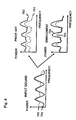
- Fig. 4 shows power spectrums of a voice section containing voices, other than noise, such as a voice of a speaker.
- a power spectrum 701 of the input sound of the AGC contains a power spectrum 702 of the voice component.
- the power spectrum 701 changes like a power spectrum 703 in the prior art AGC shown in Fig. 21 because the whole band is amplified homogeneously.
- the noise component is also amplified together with the voice component and sound offensive to ears is outputted.
- fluctuation of the level of the noise component occurs, causing sound more offensive to the ears, because the gain changes between the voice section and the non-voice section.
- the power spectrum 701 changes like a power spectrum 704 in the AGC in Fig. 3 because the bands whose SNR is low are not amplified and only the bands whose SNR is high are selectively amplified. Accordingly, it becomes possible to amplify only the voice components without amplifying the noise components.
- Fig. 5 shows powers of the output signals after mixing the receiving signals of the two points.
- the sound level becomes constant by adjusting the receiving signals S1 and S2 by the AGCs in the prior art volume control method shown in Fig. 20
- the SNR after mixing becomes low.
- the SNR after mixing becomes large as compared to the prior art in the volume control method in Fig. 1 by applying the AGC after adjusting the noise levels between the points.
- FIG. 1 shows the case when the receiving signals from the two points are processed, the same applies to a case when receiving signals of three or more points are processed.
- Fig. 6 shows an exemplary configuration of a case when the AGC in Fig. 3 is applied to a receiving section of a cellular phone.
- a decoding section 901 decodes a receiving signal and outputs it to an AGC 902 and the AGC 902 adjusts a gain of the signal outputted out of the decoding section 901 and outputs it to a speaker 903.
- Fig. 7 shows an exemplary configuration of the AGC 902 in Fig. 6 .
- This AGC has the FFT 601, the noise spectrum estimating section 602, the SNR estimating section 603, the gain calculating section 605, the multiplier 606, the IFFT 607, a voice action detecting section 1001 (VAD), an average voice level calculating section 1002 and a target gain calculating section 1003.
- VAD voice action detecting section 1001
- the VAD 1001 detects voice sections and non-voice sections from an input signal and the average voice level calculating section 1002 calculates an average voice level from an average level of the voice sections.
- the target gain calculating section 1003 calculates a target gain G0 from a ratio between the average voice level and a target level.
- the FFT 601 calculates an input spectrum by performing the FFT on the input signal.
- the noise spectrum estimating section 602 detects the voice sections and the non-voice sections by detecting a speech action from the input spectrum and calculates a noise spectrum from an average level of the non-voice sections.
- the SNR estimating section 603 calculates a SNR spectrum from the input spectrum and the noise spectrum.
- the i-th factor ⁇ (i) is determined corresponding to the SNR of the i-th band contained in the SNR spectrum.
- ⁇ (i) takes a value as shown in Fig. 8 for example when G0 and G(i) are represented by logarithmic gain.
- ⁇ (i) of the band whose SNR is 0 to 2 dB is zero and ⁇ (i) of the band whose SNR exceeds 6 dB is 1.
- ⁇ (i) of the band whose SNR is 2 to 6 dB assumes a value from zero to 1. Accordingly, G(i) of the band whose SNR is 0 to 2dB turns out to be 0, G(i) of the band whose SNR exceeds 6 dB coincides with G0 and G(i) of the band whose SNR is 2 to 6 dB assumes a value from 0 to G0.
- the multiplier 606 multiplies G(i) with the power of the i-th band in the input spectrum to calculate an output spectrum and the IFFT 607 perform the IFFT on the output spectrum to generate an output signal.
- Fig. 9 shows an exemplary configuration in which the AGC in Fig. 7 is applied to the multi-point teleconferencing apparatus.
- a teleconference is carried out among three points in this case.
- the multi-point teleconferencing apparatus has a noise volume estimating section 1201, an inter-point volume control section 1202, AGCs 1203 and 1204 and a mixer 1205.
- An operation of the noise volume estimating section 1201 is the same with the noise volume estimating sections 401 and 402 in Fig. 1 and operations of the inter-point volume control section 1202 and the mixer 1205 are the same with those of the inter-point volume control section 403 and the mixer 406 in Fig. 1 .
- the AGCs 1203 and 1204 have the same configuration with that shown in Fig. 7 .
- Fig. 10 illustrates exemplary sound control in the multi-point teleconferencing apparatus in Fig. 9 .
- the noise volume estimating section 1201 calculates a noise level of each point at first.
- the noise volume estimating section 1201 calculates a noise level 1303 (-60 dBov) from power 1301 of the receiving signal S1 and calculates a noise level 1304 (-80 dBov) from power 1302 of the receiving signal S2.
- the noise level 1304 corresponds to a minimum value of the noise level.
- the inter-point volume control section 1202 attenuates the receiving signal S1 so that the noise level 1303 coincides with the noise level 1304. Thereby, the power 1301 of the receiving signal S1 changes like power 1305.
- the AGC 1203 amplifies only the voice components of the receiving signal S1 to a target level 1306 (-26 dBov). Thereby, the power 1305 of the receiving signal S1 changes like power 1307. Meanwhile, the voice components of the receiving signal S2 have been already reaching to the target level 1306.
- the mixer 1205 generates the output signal by mixing adjusted signals from the AGCs 1203 and 1204.
- a voice level of the generated output signal is -26 dBov and a noise level thereof is -80 dBov.
- the AGC 201 amplifies the receiving signal S1 to the target level 1306 as shown in Fig. 11 .
- the power 1301 of the receiving signal S1 changes like power 1401 and a noise level 1303 rises to a noise level 1402 (-40 dBov).
- the mixer 203 outputs the output signal by mixing the adjusted signals from the AGCs 201 and 202.
- a voice level of the generated output signal is -26 dBov and a noise level is -40 dBov.
- the noise level after mixing is -40 dBov in the prior art, it is -80 dBov in the invention and the apparatus of the invention can lower the noise level.
- Fig. 12 shows another exemplary configuration of the multi-point teleconferencing apparatus.
- This multi-point teleconferencing apparatus has a configuration in which the inter-point volume control section 1202 in the configuration in Fig. 9 is replaced with an inter-point volume control section 1502 and a SNR estimating section 1501 is added.
- the SNR estimating section 1501 calculates SNRs of the receiving signals S1 and S2 and outputs them to the inter-point volume control section 1502.
- the inter-point volume control section 1502 finds a maximum value of the SNRs from the SNR estimating section 1501 and calculates a target noise level from a difference between the maximum value of the SNR and a target level. Then, the inter-point volume control section 1502 adjusts the level of the receiving signal of each point so that the noise levels of all of the points are adjusted to the target level.
- Fig. 13 shows an exemplary volume control of the multi-point teleconferencing apparatus in Fig. 12 .
- the noise volume estimating section 1201 calculates a noise level of each point at first and the SNR estimating section 1501 calculates SNR of each point. They calculate a voice level 1603 (-50 dBov) and a noise level 1605 (-60 dBov) from power 1601 of the receiving signal S1, and the SNR of the receiving signal S1 turns out to be 10 dB. They also calculate a voice level 1604 (-60 dBov) and a noise level 1606 (-80 dBov) from power 1602 of the receiving signal S2 and, the SNR of the receiving signal S2 turns out to be 20 dB.
- the inter-point volume control section 1502 calculates a target noise level 1608 (-46 dBov) by subtracting the maximum value 20dB of the SNR from a target level 1607 (-26 dBov). Then, the receiving signals S1 and S2 are amplified respectively so that the noise levels 1606 and 1606 coincide with the target noise level 1608. Thereby, the power 1601 of the receiving signal S1 changes like power 1609 and a voice level 1611 thereof turns out to be -36 dBov. The power 1602 of the receiving signal S2 changes like power 1610 and a voice level thereof coincides with the target level 1607 (-26 dBov).
- the AGC 1203 amplifies only the voice component of the receiving signal S1 to the target level 1607 (-26 dBov). Thereby, the power 1609 of the receiving signal S1 changes like power 1612. Meanwhile, the voice component of the receiving signal S2 has been already reaching to the target level 1607.
- the mixer 1205 generates the output signal by mixing adjusted signals from the AGCs 1203 and 1204.
- a sound level of the generated output signal is -26 dBov and a noise level thereof is -46 dBov.
- the AGC 201 amplifies the receiving signal S1 to the target level 1607 as shown in Fig. 14 and the AGC 202 amplifies the receiving signal S2 to the target level 1607.
- power 1601 of the receiving signal S1 changes like power 1701 and a noise level 1605 rises to a noise level 1703 (-36 dBov).
- power 1602 of the receiving signal S2 changes like power 1702 and a noise level 1606 rises to a noise level 1704 (-46 dBov).
- the mixer 203 outputs the output signal by mixing the adjusted signals from the AGCs 201 and 202.
- a voice level of the generated output signal is -26 dBov and a noise level is -36 dBov.
- the noise level after mixing is -36 dBov in the prior art, it is -46 dBov in the invention and the apparatus of the invention can lower the noise level.
- Fig. 15 shows a still other exemplary configuration of the multi-point teleconferencing apparatus.
- This multi-point teleconferencing apparatus has a noise volume estimating section 1801, a SNR estimating section 1802, an inter-point volume control section 1803, AGCs 1804 through 1806 and a mixer 1807 and generates an output signal from three receiving signals S1 through S3 in the same manner with the multi-point teleconferencing apparatus in Fig. 12 .
- Fig. 16 shows exemplary volume control in the multi-point teleconferencing apparatus in Fig. 15 .
- the noise volume estimating section 1801 calculates noise levels of the respective points at first and the SNR estimating section 1802 calculates SNRs of the respective point.
- Voice levels of the receiving signals S1, S2 and S3 are -10 dBov, -30 dBov and -40 dBov (1901), respectively, and noise levels thereof are -30 dBov, -60 dBov and -80 dBov (1902), respectively.
- SNRs thereof are 20 dB, 30 dB and 40 dB (1903), respectively.
- the inter-point volume control section 1803 subtracts a SNR maximum value of 40 dB from the target level (-25 dBov) to calculate a target noise level (-65 dBov). Then, it adjusts the receiving signals S1, S2 and S3 so that the respective noise levels coincide with the target noise level. Thereby, the voice levels of the receiving signals S1, S2 and S3 turn out to be -45 dBov, -35 dBov and -25 dBov (1904) and the noise level turns out to be -65 dBov (1905).
- the AGCs 1804 and 1805 amplify only the voice components of the receiving signals S1 and S2 to the target level (-25 dBov). Thereby, the voice level of the receiving signals S1, S2 and S3 turn out to be -25 dBov (1906). Meanwhile, the noise level is kept to be -65 dBov (1907).
- the mixer 1807 outputs the output signal by mixing the adjusted signals from the AGCs 1804 through 1806.
- a voice level of the generated output signal turns out to be - 25 dBov (1908) and a noise level thereof turns out to be -65 dBov (1909).
- Fig. 17 shows the prior art exemplary volume control shown in Fig. 20 .
- Voice levels (2001) and noise levels (2002) of receiving signals S1, S2 and S3 are the same with those shown in Fig. 16 in this case.
- the AGCs adjust these receiving signals to the target level (-25 dBov).
- voice levels of the receiving signals S1, S2 and S3 turn out to be -25 dBov (2003) and noise levels thereof turn out to be -45 dBov, -55 dBov and -65 dBov (2004), respectively.
- a voice level of the generated output signal turns out to be -25 dBov (2005) and a noise level thereof turns out to be -45 dBov (2006).
- the noise level after mixing is -45 dBov according to the prior art, it is 65 dBov according to the invention and the apparatus of the invention can lower the noise level.
- FIGs. 12 and 15 show the configurations for processing the receiving signals from two and three points, respectively, the same applies to a configuration for processing receiving signals from four or more points.
- Fig. 18 shows another exemplary configuration of the AGCs shown in Figs. 6 , 9 , 12 and 15 .
- a voice action is detected based on an input spectrum instead of receiving signals in this configuration.
- the AGC has the FFT 601, the SNR estimating section 603, the gain calculating section 605, the multiplier 606, the IFFT 607, a noise spectrum estimating section 2101, a VAD 2102 and a target gain calculating section 2103. Among them, operations of the FFT 601, the SNR estimating section 603, the gain calculating section 605, the multiplier 606 and the IFFT 607 are the same with those shown in Fig. 7 .
- the VAD 2102 detects voice sections and non-voice sections from the input spectrum and the noise spectrum estimating section calculates a noise spectrum from an average level of the non-voice sections and outputs it to the SNR estimating section 603.
- the target gain calculating section 2103 calculates an average voice level from an average level of the voice sections, calculates a target gain G0 from a ratio between the average voice level and the target level and outputs it to the gain calculating section 605.
- voice may distort if the voice is amplified to much by the AGC and the SNR drops if the Voice is attenuated. Then, it is desirable to set upper and lower limits for the calculated target gain. When the calculated target gain exceeds the upper limit, the target gain is replaced with a value of the upper limit and when the calculated target gain is lower than the lower limit, the target gain is replaced with a value of the lower limit. Zero dB is used as the lower limit of the target gain for example.
- the voice may also distort when the noise level of a certain point is too small because the SNR becomes large and a large gain is set and the voice is clipped when the noise level is too large in the multi-point teleconferencing apparatus. Then, it is desirable to provide a noise superimposing section for superimposing low level noise to a receiving signal inputted to the inter-point volume control section. Thereby, it becomes possible to assure noise of certain level or more for each point.
- the target gain calculating section within the AGC has calculated the target gain from the target level common to the all bands in the embodiments described above, it is also possible, instead of that, to calculate the target gain different per each band from the target level different per each band.
- the AGC may perform the automatic gain control based on an amplitude spectrum of the input sound instead.
- the FFT outputs the amplitude spectrum of the input sound as an input spectrum and the multiplier generates an output spectrum by multiplying G(i) with the i-th band in the input spectrum.
- a multipoint communication apparatus also achieves the performance of adjusting gains of signals receiving from a plurality of other communication apparatuses by processing at a CPU in the multipoint communication apparatus.
- the invention also provides a computer program or a computer program product for carrying out any of the methods described herein, and a computer readable medium having stored thereon a program for carrying out any of the methods described herein.
- a computer program embodying the invention may be stored on a computer-readable medium, or it could, for example, be in the form of a signal such as a downloadable data signal provided from an Internet website, or it could be in any other form.
Abstract
Description
- The present invention relates to a sound volume control unit and a method for automatically adjusting sound volume of sound signals.
- A multi-point speech system for speaking among two or more points by using cellular phones, IP (Internet Protocol) telephones, television conference systems and the like has come to be used lately. In such multi-point speech system, sound volume of receiving signals may differ per point due to sensitivity of microphones of transmitting-side units of the respective points even if reproducing volume of a receiving-side unit is set at certain level.
-
Fig. 19 shows an exemplary configuration of such multi-point speech system. Transmitting-side telephones side telephone 104 are connected to acommunication network 103. Thetelephone 104 receives a voice signal S1 from thetelephone 101 and a voice signal S2 from thetelephone 102 and aspeaker 105 converts output signals and outputs as voice. - When volume of the voice signal S1 is large and volume of the voice signal S2 is small at this time, volume of the voices outputted out of the
speaker 105 differs between those from thetelephone 101 and thetelephone 102. Then, it has been desired to automatically adjust the volumes of the receiving signals in order to make the volumes of sounds of the all points even. -
Fig. 20 shows a prior art sound volume control method using automatic gain controls (AGC). The AGC is a function for automatically adjusting an amplification factor (gain) of an amplifying circuit so that volume of an output is adjusted to a desirable level even when amplitude of an input signal fluctuates. - A
mixer 203 performs mixing (addition) in this volume control method after leveling the volumes of the receiving signals S1 and S2 of the respective points by theAGCs AGCs -
Fig. 21 is a structural view of an AGC described in a non-patent literature, Peter L. Chu, "VOICE-ACTIVATED AGC FOR TELECONFERENCING" proceedings ICASSP96 vol.2, pp.929-932, 1996. According to this configuration, a frame electricpower calculating section 301 divides an input signal into frames of 20 ms and calculates energy (frame power) within each frame. Next, a maximumvalue calculating section 302 calculates a maximum value of the frame power from the past to the present time and again calculating section 303 calculates a gain from a difference of powers between the maximum value and a target level. Then, amultiplier 304 multiplies the gain with the input signal to generate an output signal. - However, although the volumes of voices of speakers in the output signals of the AGC are almost leveled in all of the points, volume of noise that depends on an ambient environment differs per each point. Still more, a SNR (Signal-to-Noise Ratio) of each point does not change. Accordingly, a SNR of an output signal after mixing is adjusted to a value of a point where the SNR of the receiving signal is least among all of the points. Therefore, when there is such point where the SNR is small, the SNR of all of the points becomes small and it becomes hard to catch the voices.
- Japanese Patent Application Laid-open No.
2004-133403 - Japanese Patent Application Laid-open No.
2004-507141 2002-223268 2002-1575100 - According to an aspect of an embodiment, a multipoint communication apparatus comprises: a receiving unit for receiving a plurality of signals containing voice signal elements and noise signal elements from the plurality of other communication apparatuses, respectively; a noise estimating unit for estimating the plurality of noise signal elements in the plurality of received signals, respectively; a gain control unit for adjusting gains of the plurality of signals passing therethrough so as to equalize the levels of the plurality of noise signal elements outputted from the gain element on the basis of the estimated levels of the noise signal elements ; a combining unit for combining the plurality of signals passed through the gain control unit; and an output unit for outputting a sound signal on the basis of the a combined signal by the combining unit.
-
-
Fig. 1 is a structural view of a first multi-point teleconferencing apparatus; -
Fig. 2 is a structural view of an inter-point sound volume control section; -
Fig. 3 is a structural view of a first AGC; -
Fig. 4 illustrates charts showing power spectrums of a voice section; -
Fig. 5 illustrates charts showing powers after mixing; -
Fig. 6 is a structural view of a receiving section of a cellular phone; -
Fig. 7 is a structural view of a second AGC; -
Fig. 8 is a graph showing a relationship between a multiplication factor and SNR; -
Fig. 9 is a structural view of a second multi-point teleconferencing apparatus; -
Fig. 10 illustrates charts showing first volume control of the invention; -
Fig. 11 illustrates charts showing prior art first volume control; -
Fig. 12 is a structural view of a third multi-point teleconferencing apparatus; -
Fig. 13 illustrates charts showing second volume control of the invention; -
Fig. 14 illustrates charts showing prior art second volume control; -
Fig. 15 is a structural view of a fourth multi-point teleconferencing apparatus; -
Fig. 16 illustrates charts showing third volume control of the invention; -
Fig. 17 illustrates charts showing prior art third volume control; -
Fig. 18 is a structural view of a third AGC; -
Fig. 19 is a structural view of a prior art multi-point teleconference system; -
Fig. 20 is a structural view of a prior art sound volume control method; and -
Fig. 21 is a structural view of a prior art AGC. - Preferred embodiments for carrying out the invention will be explained below in detail with reference to the drawings.
-
Fig. 1 shows an exemplary configuration of a sound volume control unit (multi-point teleconferencing apparatus) applied to a multi-point teleconferencing system. A teleconference is carried out among three points in this case. This multi-point teleconferencing apparatus has noisevolume estimating sections volume control section 403,AGCs mixer 406 and outputs an output signal by adjusting sound volumes (levels) of receiving signals from two points. - The noise
volume estimating sections volume control section 403. Based on the calculation results of the noise level, the inter-pointvolume control section 403 controls levels of the receiving signals S1 and S2 so that the noise levels of the receiving signals S1 and S2 are made even and output them to theAGCs - The
AGCs volume control section 403 to a target level and themixer 406 performs mixing on the output signals from theAGCs -
Fig. 2 shows an exemplary configuration of the inter-pointvolume control section 403 inFig. 1 . The inter-pointvolume control section 403 hasamplifiers gain calculating section 503. Theamplifiers AGCs gain calculating section 503 adjusts gains of theamplifiers volume estimating sections - The
gain calculating section 503 calculates the gains of theamplifiers -
Fig. 3 shows an exemplary configuration of theAGCs Fig. 1 . This AGC includes a fast Fourier transforming section 601 (FFT), a noisespectrum estimating section 602, aSNR estimating section 603, a targetgain calculating section 604, again calculating section 605, amultiplier 606 and an inverse fast Fourier transforming section 607 (IFFT) and controls an amplification amount of each band corresponding to the SNR and a target level in a frequency domain. Each domain corresponds to each discrete value of the frequency for example. - The
FFT 601 transforms the input signal from a temporal domain to the frequency domain by orthogonal transformation to find a power spectrum (input spectrum) of input sounds. Specifically, theFFT 601 divides the input signal into a plurality of bands to calculate a band signal of each band and finds the power per band from each band signal to calculate the input spectrum. - The noise
spectrum estimating section 602 outputs a spectrum of non-voice section containing only noise signals in the input spectrum as a noise spectrum and theSNR estimating section 603 finds a SNR spectrum that is a ratio between the input spectrum and the noise spectrum. The SNR spectrum represents the SNR of each band. - The target
gain calculating section 604 calculates a target gain so that volume of the output signal is adjusted to the target level from the input spectrum and the target level and thegain calculating section 605 calculates a gain of each band from the target gain and the SNR spectrum. At this time, thegain calculating section 605 calculates the gain of each band so that the gain is adjusted to the target gain in the band whose SNR is high and so that the gain is adjusted to 1 in the band whose SNR is low, i.e., so as not to be amplified. - The
multiplier 606 multiplies the gain of each band with each band of the input spectrum to adjust the level of each band. TheIFFT 607 generates an output signal by transforming the input signal from the frequency domain to the temporal domain by orthogonal inverse transformation. - Such AGC allows only voice components whose SNR is high to be adjusted to the target level without changing the noise components whose SNR is low.
-
Fig. 4 shows power spectrums of a voice section containing voices, other than noise, such as a voice of a speaker. Apower spectrum 701 of the input sound of the AGC contains apower spectrum 702 of the voice component. - The
power spectrum 701 changes like apower spectrum 703 in the prior art AGC shown inFig. 21 because the whole band is amplified homogeneously. In this case, the noise component is also amplified together with the voice component and sound offensive to ears is outputted. In addition to that, fluctuation of the level of the noise component occurs, causing sound more offensive to the ears, because the gain changes between the voice section and the non-voice section. - In contrary to that, the
power spectrum 701 changes like apower spectrum 704 in the AGC inFig. 3 because the bands whose SNR is low are not amplified and only the bands whose SNR is high are selectively amplified. Accordingly, it becomes possible to amplify only the voice components without amplifying the noise components. -
Fig. 5 shows powers of the output signals after mixing the receiving signals of the two points. Although the sound level becomes constant by adjusting the receiving signals S1 and S2 by the AGCs in the prior art volume control method shown inFig. 20 , the SNR after mixing becomes low. In contrary to that, the SNR after mixing becomes large as compared to the prior art in the volume control method inFig. 1 by applying the AGC after adjusting the noise levels between the points. - Although
Fig. 1 shows the case when the receiving signals from the two points are processed, the same applies to a case when receiving signals of three or more points are processed. -
Fig. 6 shows an exemplary configuration of a case when the AGC inFig. 3 is applied to a receiving section of a cellular phone. Adecoding section 901 decodes a receiving signal and outputs it to anAGC 902 and theAGC 902 adjusts a gain of the signal outputted out of thedecoding section 901 and outputs it to aspeaker 903. -
Fig. 7 shows an exemplary configuration of theAGC 902 inFig. 6 . This AGC has theFFT 601, the noisespectrum estimating section 602, theSNR estimating section 603, thegain calculating section 605, themultiplier 606, theIFFT 607, a voice action detecting section 1001 (VAD), an average voicelevel calculating section 1002 and a targetgain calculating section 1003. - The
VAD 1001 detects voice sections and non-voice sections from an input signal and the average voicelevel calculating section 1002 calculates an average voice level from an average level of the voice sections. The targetgain calculating section 1003 calculates a target gain G0 from a ratio between the average voice level and a target level. - The
FFT 601 calculates an input spectrum by performing the FFT on the input signal. The noisespectrum estimating section 602 detects the voice sections and the non-voice sections by detecting a speech action from the input spectrum and calculates a noise spectrum from an average level of the non-voice sections. TheSNR estimating section 603 calculates a SNR spectrum from the input spectrum and the noise spectrum. - The
gain calculating section 605 calculates a gain G(i) from an i-th band from the target gain G0 and the SNR spectrum by the following expression:
- Where, the i-th factor β(i) is determined corresponding to the SNR of the i-th band contained in the SNR spectrum.
- β(i) takes a value as shown in
Fig. 8 for example when G0 and G(i) are represented by logarithmic gain. In this case, β(i) of the band whose SNR is 0 to 2 dB is zero and β(i) of the band whose SNR exceeds 6 dB is 1. β(i) of the band whose SNR is 2 to 6 dB assumes a value from zero to 1. Accordingly, G(i) of the band whose SNR is 0 to 2dB turns out to be 0, G(i) of the band whose SNR exceeds 6 dB coincides with G0 and G(i) of the band whose SNR is 2 to 6 dB assumes a value from 0 to G0. - The
multiplier 606 multiplies G(i) with the power of the i-th band in the input spectrum to calculate an output spectrum and theIFFT 607 perform the IFFT on the output spectrum to generate an output signal. -
Fig. 9 shows an exemplary configuration in which the AGC inFig. 7 is applied to the multi-point teleconferencing apparatus. A teleconference is carried out among three points in this case. The multi-point teleconferencing apparatus has a noisevolume estimating section 1201, an inter-pointvolume control section 1202, AGCs 1203 and 1204 and amixer 1205. - An operation of the noise
volume estimating section 1201 is the same with the noisevolume estimating sections Fig. 1 and operations of the inter-pointvolume control section 1202 and themixer 1205 are the same with those of the inter-pointvolume control section 403 and themixer 406 inFig. 1 . TheAGCs Fig. 7 . -
Fig. 10 illustrates exemplary sound control in the multi-point teleconferencing apparatus inFig. 9 . The noisevolume estimating section 1201 calculates a noise level of each point at first. The noisevolume estimating section 1201 calculates a noise level 1303 (-60 dBov) frompower 1301 of the receiving signal S1 and calculates a noise level 1304 (-80 dBov) frompower 1302 of the receiving signal S2. In this case, thenoise level 1304 corresponds to a minimum value of the noise level. - Then, the inter-point
volume control section 1202 attenuates the receiving signal S1 so that thenoise level 1303 coincides with thenoise level 1304. Thereby, thepower 1301 of the receiving signal S1 changes likepower 1305. - Next, the
AGC 1203 amplifies only the voice components of the receiving signal S1 to a target level 1306 (-26 dBov). Thereby, thepower 1305 of the receiving signal S1 changes likepower 1307. Meanwhile, the voice components of the receiving signal S2 have been already reaching to thetarget level 1306. - Next, the
mixer 1205 generates the output signal by mixing adjusted signals from theAGCs - In contrary to that, according to the prior art volume control method shown in
Fig. 20 , theAGC 201 amplifies the receiving signal S1 to thetarget level 1306 as shown inFig. 11 . Thereby, thepower 1301 of the receiving signal S1 changes likepower 1401 and anoise level 1303 rises to a noise level 1402 (-40 dBov). - Next, the
mixer 203 outputs the output signal by mixing the adjusted signals from theAGCs - Thus, although the noise level after mixing is -40 dBov in the prior art, it is -80 dBov in the invention and the apparatus of the invention can lower the noise level.
-
Fig. 12 shows another exemplary configuration of the multi-point teleconferencing apparatus. This multi-point teleconferencing apparatus has a configuration in which the inter-pointvolume control section 1202 in the configuration inFig. 9 is replaced with an inter-pointvolume control section 1502 and aSNR estimating section 1501 is added. - The
SNR estimating section 1501 calculates SNRs of the receiving signals S1 and S2 and outputs them to the inter-pointvolume control section 1502. The inter-pointvolume control section 1502 finds a maximum value of the SNRs from theSNR estimating section 1501 and calculates a target noise level from a difference between the maximum value of the SNR and a target level. Then, the inter-pointvolume control section 1502 adjusts the level of the receiving signal of each point so that the noise levels of all of the points are adjusted to the target level. -
Fig. 13 shows an exemplary volume control of the multi-point teleconferencing apparatus inFig. 12 . The noisevolume estimating section 1201 calculates a noise level of each point at first and theSNR estimating section 1501 calculates SNR of each point. They calculate a voice level 1603 (-50 dBov) and a noise level 1605 (-60 dBov) frompower 1601 of the receiving signal S1, and the SNR of the receiving signal S1 turns out to be 10 dB. They also calculate a voice level 1604 (-60 dBov) and a noise level 1606 (-80 dBov) frompower 1602 of the receiving signal S2 and, the SNR of the receiving signal S2 turns out to be 20 dB. - Next, the inter-point
volume control section 1502 calculates a target noise level 1608 (-46 dBov) by subtracting the maximum value 20dB of the SNR from a target level 1607 (-26 dBov). Then, the receiving signals S1 and S2 are amplified respectively so that thenoise levels target noise level 1608. Thereby, thepower 1601 of the receiving signal S1 changes likepower 1609 and avoice level 1611 thereof turns out to be -36 dBov. Thepower 1602 of the receiving signal S2 changes likepower 1610 and a voice level thereof coincides with the target level 1607 (-26 dBov). - Next, the
AGC 1203 amplifies only the voice component of the receiving signal S1 to the target level 1607 (-26 dBov). Thereby, thepower 1609 of the receiving signal S1 changes likepower 1612. Meanwhile, the voice component of the receiving signal S2 has been already reaching to thetarget level 1607. - Next, the
mixer 1205 generates the output signal by mixing adjusted signals from theAGCs - In contrary to that, according to the prior art volume control method shown in
Fig. 20 , theAGC 201 amplifies the receiving signal S1 to thetarget level 1607 as shown inFig. 14 and theAGC 202 amplifies the receiving signal S2 to thetarget level 1607. Thereby,power 1601 of the receiving signal S1 changes likepower 1701 and anoise level 1605 rises to a noise level 1703 (-36 dBov). Also,power 1602 of the receiving signal S2 changes likepower 1702 and anoise level 1606 rises to a noise level 1704 (-46 dBov). - Next, the
mixer 203 outputs the output signal by mixing the adjusted signals from theAGCs - Thus, although the noise level after mixing is -36 dBov in the prior art, it is -46 dBov in the invention and the apparatus of the invention can lower the noise level.
-
Fig. 15 shows a still other exemplary configuration of the multi-point teleconferencing apparatus. A teleconference is carried out among four points in this case. This multi-point teleconferencing apparatus has a noisevolume estimating section 1801, aSNR estimating section 1802, an inter-pointvolume control section 1803, AGCs 1804 through 1806 and amixer 1807 and generates an output signal from three receiving signals S1 through S3 in the same manner with the multi-point teleconferencing apparatus inFig. 12 . -
Fig. 16 shows exemplary volume control in the multi-point teleconferencing apparatus inFig. 15 . The noisevolume estimating section 1801 calculates noise levels of the respective points at first and theSNR estimating section 1802 calculates SNRs of the respective point. Voice levels of the receiving signals S1, S2 and S3 are -10 dBov, -30 dBov and -40 dBov (1901), respectively, and noise levels thereof are -30 dBov, -60 dBov and -80 dBov (1902), respectively. Accordingly, SNRs thereof are 20 dB, 30 dB and 40 dB (1903), respectively. - Next, the inter-point
volume control section 1803 subtracts a SNR maximum value of 40 dB from the target level (-25 dBov) to calculate a target noise level (-65 dBov). Then, it adjusts the receiving signals S1, S2 and S3 so that the respective noise levels coincide with the target noise level. Thereby, the voice levels of the receiving signals S1, S2 and S3 turn out to be -45 dBov, -35 dBov and -25 dBov (1904) and the noise level turns out to be -65 dBov (1905). - Next, the
AGCs - Next, the
mixer 1807 outputs the output signal by mixing the adjusted signals from theAGCs 1804 through 1806. A voice level of the generated output signal turns out to be - 25 dBov (1908) and a noise level thereof turns out to be -65 dBov (1909). -
Fig. 17 shows the prior art exemplary volume control shown inFig. 20 . Voice levels (2001) and noise levels (2002) of receiving signals S1, S2 and S3 are the same with those shown inFig. 16 in this case. The AGCs adjust these receiving signals to the target level (-25 dBov). Thereby, voice levels of the receiving signals S1, S2 and S3 turn out to be -25 dBov (2003) and noise levels thereof turn out to be -45 dBov, -55 dBov and -65 dBov (2004), respectively. - Next, mixing is performed on the adjusted signals to generate an output signal. A voice level of the generated output signal turns out to be -25 dBov (2005) and a noise level thereof turns out to be -45 dBov (2006).
- Thus, while the noise level after mixing is -45 dBov according to the prior art, it is 65 dBov according to the invention and the apparatus of the invention can lower the noise level.
- Although
Figs. 12 and15 show the configurations for processing the receiving signals from two and three points, respectively, the same applies to a configuration for processing receiving signals from four or more points. -
Fig. 18 shows another exemplary configuration of the AGCs shown inFigs. 6 ,9 ,12 and15 . A voice action is detected based on an input spectrum instead of receiving signals in this configuration. - The AGC has the
FFT 601, theSNR estimating section 603, thegain calculating section 605, themultiplier 606, theIFFT 607, a noisespectrum estimating section 2101, aVAD 2102 and a targetgain calculating section 2103. Among them, operations of theFFT 601, theSNR estimating section 603, thegain calculating section 605, themultiplier 606 and theIFFT 607 are the same with those shown inFig. 7 . - The
VAD 2102 detects voice sections and non-voice sections from the input spectrum and the noise spectrum estimating section calculates a noise spectrum from an average level of the non-voice sections and outputs it to theSNR estimating section 603. The targetgain calculating section 2103 calculates an average voice level from an average level of the voice sections, calculates a target gain G0 from a ratio between the average voice level and the target level and outputs it to thegain calculating section 605. - By the way, voice may distort if the voice is amplified to much by the AGC and the SNR drops if the Voice is attenuated. Then, it is desirable to set upper and lower limits for the calculated target gain. When the calculated target gain exceeds the upper limit, the target gain is replaced with a value of the upper limit and when the calculated target gain is lower than the lower limit, the target gain is replaced with a value of the lower limit. Zero dB is used as the lower limit of the target gain for example.
- The voice may also distort when the noise level of a certain point is too small because the SNR becomes large and a large gain is set and the voice is clipped when the noise level is too large in the multi-point teleconferencing apparatus. Then, it is desirable to provide a noise superimposing section for superimposing low level noise to a receiving signal inputted to the inter-point volume control section. Thereby, it becomes possible to assure noise of certain level or more for each point.
- It is also possible to set upper and lower limits for the noise level of each point, instead of superimposing the low level noise. In this case, when the noise level exceeds the upper limit, the noise level is replaced with a value of the upper limit and when the noise level is lower than the lower limit, the noise level is replaced with a value of the lower limit.
- Although the target gain calculating section within the AGC has calculated the target gain from the target level common to the all bands in the embodiments described above, it is also possible, instead of that, to calculate the target gain different per each band from the target level different per each band.
- Still more, although the AGC has performed the automatic gain control based on the power spectrum of the input sound, it may perform the automatic gain control based on an amplitude spectrum of the input sound instead. In this case, the FFT outputs the amplitude spectrum of the input sound as an input spectrum and the multiplier generates an output spectrum by multiplying G(i) with the i-th band in the input spectrum.
- A multipoint communication apparatus also achieves the performance of adjusting gains of signals receiving from a plurality of other communication apparatuses by processing at a CPU in the multipoint communication apparatus.
- In any of the above aspects, the various features may be implemented in hardware, or as software modules running on one or more processors. Features of one aspect may be applied to any of the other aspects.
- The invention also provides a computer program or a computer program product for carrying out any of the methods described herein, and a computer readable medium having stored thereon a program for carrying out any of the methods described herein. A computer program embodying the invention may be stored on a computer-readable medium, or it could, for example, be in the form of a signal such as a downloadable data signal provided from an Internet website, or it could be in any other form.
Claims (14)
- A multipoint communication apparatus for controlling and outputting a signal by combining a plurality of signals receiving from a plurality of other communication apparatuses, comprising:a receiving unit for receiving a plurality of signals containing voice signal elements and noise signal elements from the plurality of other communication apparatuses, respectively;a noise estimating unit for estimating the plurality of noise signal elements in the plurality of received signals, respectively;a gain control unit for adjusting gains of the plurality of signals passing therethrough so as to equalize the levels of the plurality of noise signal elements outputted from the gain element on the basis of the estimated levels of the noise signal elements ;a combining unit for combining the plurality of signals passed through the gain control unit; andan output unit for outputting a sound signal on the basis of a combined signal by the combining unit.
- The multipoint communication apparatus according to claim 1, wherein the gain control unit adjusts a gain of the voice signal elements in the controlled signal to a target gain.
- The multipoint communication apparatus according to claim 1 or 2, further comprising:a noise superimposing unit for superimposing low level noise elements to the plurality of signals.
- The multipoint communication apparatus according to any of the preceding claims, wherein the gain control unit replaces the plurality of noise volume elements respectively to an upper limit value when the noise volume elements is larger than the upper limit value and replaces the plurality of noise volume elements respectively to a lower limit value when the noise volume elements is smaller than the lower limit value.
- The multipoint communication apparatus according to any of the preceding claims, further comprising:a plurality of second gain control units for controlling a gain of the controlled signal outputted out of the control unit respectively;wherein the each second gain control unit comprises:a spectrum generating unit for dividing the controlled signal outputted out of the control unit into a plurality of bands and generating an input spectrum representing a signal level of the each band;a noise spectrum estimating unit for finding a noise spectrum representing a noise level of the each band from the signal level of the each band;a signal-to-noise ratio estimating unit for finding a signal-to-noise ratio of the each band from a ratio between the input spectrum and the noise spectrum;a gain calculating unit for finding a gain of the each band from a target gain and the signal-to-noise ratio of the each band; anda multiplier for finding an output level of the each band by multiplying the signal level of the each band with the gain of each band.
- The multipoint communication apparatus according to claim 5, wherein the plurality of gain control units further comprises:a target gain calculating unit for finding the target gain from a target volume and the volume of the controlled signal inputted from the control unit.
- The multipoint communication apparatus according to claim 5, wherein the plurality of gain control units further comprises:a target gain calculating unit for finding the target gain from a target volume and the signal level of each band.
- A multipoint communication apparatus for controlling and outputting a signal by combining a plurality of signals receiving from a plurality of other communication apparatuses, comprising:a receiving unit for receiving a plurality of signals containing voice volume elements and noise volume elements from the plurality of other communication apparatuses respectively;a noise volume estimating unit for calculating the plurality of noise volume elements in the plurality of received signals respectively;a signal-to-noise ratio estimating unit for finding the plurality of signal-to-noise ratios of the plurality of receiving signals in accordance with the estimated noise volume elements respectively;a control unit for finding the largest signal-to-noise ratio of the receiving signal in the plurality of signal-to-noise and finding a target noise volume from the largest signal-to-noise ratio of the receiving signal and controlling the plurality of signals to adjust to the target noise volume.a combining unit for combining the plurality of controlled signals; andan output unit for outputting a combined signal.
- A multipoint communication apparatus for controlling and outputting a signal by combining a plurality of signals receiving from a plurality of other communication apparatuses, comprising:a receiving unit for receiving a plurality of signals containing voice volume elements and noise volume elements from the plurality of other communication apparatuses respectively;a noise volume estimating unit for calculating the plurality of noise volume elements in the plurality of received signals respectively;a control unit for controlling the plurality of signals to adjust the plurality of noise volume elements of the plurality of signals to a predetermined noise volume respectively;a combining unit for combining the plurality of controlled signals; andan output unit for outputting a combined signal.
- A volume control unit comprising:a spectrum generating unit for dividing a input signal containing voice volume elements and noise volume elements into a plurality of bands and generating a plurality of input spectra representing a signal level of the each band respectively;a noise spectrum estimating unit for finding a plurality of noise spectra representing a noise level of the each band from the signal level of the each band respectively;a signal-to-noise ratio estimating unit for finding a plurality of signal-to-noise ratios of the each band from a ratio between the input spectrum and the noise spectrum respectively;a gain calculating unit for finding a plurality of gains of the each band from a target gain and the signal-to-noise ratio of the each band respectively; anda multiplier for finding a plurality of output levels of the each band by multiplying the signal level of the each band with the gain of each band respectively.
- The volume control unit according to claim 10 further comprising:a target gain calculating unit for finding the target gain from a target volume the volume of the input signal.
- The volume control unit according to claim 10, further comprising:a target gain calculating unit for finding the target gain from the target volume and the signal level of each band.
- The volume control unit according to claim 10, 11 or 12, wherein the target gain calculating unit sets the target gain as an upper limit value when the target gain is larger than the upper limit value and sets the target gain as a lower limit value when the target gain is smaller than the lower limit value.
- A multipoint communication apparatus for controlling and outputting a signal by combining a plurality of signals receiving from a plurality of other communication apparatuses, comprising:a receiving unit for receiving a plurality of signals containing voice signal elements and noise signal elements from the plurality of other communication apparatuses, respectively;a processor for performing a process of adjusting gains of the plurality of signals comprising the steps of:estimating the plurality of noise signal elements in the plurality of received signals, respectively;adjusting gains of the plurality of signals passing therethrough so as to equalize the levels of the plurality of noise signal elements outputted from the gain element on the basis of the estimated levels of the noise signal elements ;combining the plurality of signals passed through the gain control unit; andan output unit for outputting a sound signal on the basis of the a combined signal by the combining unit.
Applications Claiming Priority (1)
| Application Number | Priority Date | Filing Date | Title |
|---|---|---|---|
| JP2007153789A JP4580409B2 (en) | 2007-06-11 | 2007-06-11 | Volume control apparatus and method |
Publications (3)
| Publication Number | Publication Date |
|---|---|
| EP2034710A2 true EP2034710A2 (en) | 2009-03-11 |
| EP2034710A3 EP2034710A3 (en) | 2010-03-31 |
| EP2034710B1 EP2034710B1 (en) | 2012-01-04 |
Family
ID=39828947
Family Applications (1)
| Application Number | Title | Priority Date | Filing Date |
|---|---|---|---|
| EP08157992A Expired - Fee Related EP2034710B1 (en) | 2007-06-11 | 2008-06-10 | Multipoint communication apparatus with sound level adjustment unit |
Country Status (3)
| Country | Link |
|---|---|
| US (1) | US8218777B2 (en) |
| EP (1) | EP2034710B1 (en) |
| JP (1) | JP4580409B2 (en) |
Cited By (1)
| Publication number | Priority date | Publication date | Assignee | Title |
|---|---|---|---|---|
| CN109274909A (en) * | 2018-09-19 | 2019-01-25 | 深圳创维-Rgb电子有限公司 | Television sound method of adjustment, television set and storage medium |
Families Citing this family (11)
| Publication number | Priority date | Publication date | Assignee | Title |
|---|---|---|---|---|
| JP4826625B2 (en) * | 2008-12-04 | 2011-11-30 | ソニー株式会社 | Volume correction device, volume correction method, volume correction program, and electronic device |
| JP4844622B2 (en) * | 2008-12-05 | 2011-12-28 | ソニー株式会社 | Volume correction apparatus, volume correction method, volume correction program, electronic device, and audio apparatus |
| JP5120288B2 (en) * | 2009-02-16 | 2013-01-16 | ソニー株式会社 | Volume correction device, volume correction method, volume correction program, and electronic device |
| JP5548950B2 (en) * | 2010-06-21 | 2014-07-16 | カシオ計算機株式会社 | Image processing apparatus and method, and program |
| US20130325458A1 (en) * | 2010-11-29 | 2013-12-05 | Markus Buck | Dynamic microphone signal mixer |
| TWI578755B (en) * | 2012-07-06 | 2017-04-11 | 鴻海精密工業股份有限公司 | System and method for adjusting volume of multiuser conference |
| JP6135106B2 (en) | 2012-11-29 | 2017-05-31 | 富士通株式会社 | Speech enhancement device, speech enhancement method, and computer program for speech enhancement |
| US20140278380A1 (en) * | 2013-03-14 | 2014-09-18 | Dolby Laboratories Licensing Corporation | Spectral and Spatial Modification of Noise Captured During Teleconferencing |
| EP3053356B8 (en) | 2013-10-30 | 2020-06-17 | Cerence Operating Company | Methods and apparatus for selective microphone signal combining |
| CN103680513B (en) * | 2013-12-13 | 2016-11-02 | 广州华多网络科技有限公司 | Audio signal processing method, device and server |
| JP7095586B2 (en) * | 2018-12-14 | 2022-07-05 | 富士通株式会社 | Voice correction device and voice correction method |
Citations (4)
| Publication number | Priority date | Publication date | Assignee | Title |
|---|---|---|---|---|
| JP2002175100A (en) | 2000-12-08 | 2002-06-21 | Matsushita Electric Ind Co Ltd | Adaptive noise suppression/voice-encoding device |
| JP2002223268A (en) | 2001-01-29 | 2002-08-09 | Mitsubishi Electric Corp | Voice control device and mobile telephone using the same |
| JP2004507141A (en) | 2000-08-14 | 2004-03-04 | クリアー オーディオ リミテッド | Voice enhancement system |
| JP2004133403A (en) | 2002-09-20 | 2004-04-30 | Kobe Steel Ltd | Sound signal processing apparatus |
Family Cites Families (8)
| Publication number | Priority date | Publication date | Assignee | Title |
|---|---|---|---|---|
| ES2037128T3 (en) * | 1987-05-15 | 1993-06-16 | Alcatel N.V. | VOICE CONTROL CIRCUIT FOR A TELECOMMUNICATION TERMINAL. |
| FI100840B (en) * | 1995-12-12 | 1998-02-27 | Nokia Mobile Phones Ltd | Noise attenuator and method for attenuating background noise from noisy speech and a mobile station |
| JP3454402B2 (en) * | 1996-11-28 | 2003-10-06 | 日本電信電話株式会社 | Band division type noise reduction method |
| JP3678611B2 (en) * | 1999-07-06 | 2005-08-03 | 日本電気エンジニアリング株式会社 | Audio conference system |
| JP2003060459A (en) * | 2001-08-21 | 2003-02-28 | Oki Electric Ind Co Ltd | Automatic gain control(agc) amplifier |
| JP4282317B2 (en) | 2002-12-05 | 2009-06-17 | アルパイン株式会社 | Voice communication device |
| JP2005175674A (en) * | 2003-12-09 | 2005-06-30 | Nec Corp | Signal compression/decompression device and portable communication terminal |
| US7945006B2 (en) | 2004-06-24 | 2011-05-17 | Alcatel-Lucent Usa Inc. | Data-driven method and apparatus for real-time mixing of multichannel signals in a media server |
-
2007
- 2007-06-11 JP JP2007153789A patent/JP4580409B2/en not_active Expired - Fee Related
-
2008
- 2008-06-10 US US12/155,828 patent/US8218777B2/en not_active Expired - Fee Related
- 2008-06-10 EP EP08157992A patent/EP2034710B1/en not_active Expired - Fee Related
Patent Citations (4)
| Publication number | Priority date | Publication date | Assignee | Title |
|---|---|---|---|---|
| JP2004507141A (en) | 2000-08-14 | 2004-03-04 | クリアー オーディオ リミテッド | Voice enhancement system |
| JP2002175100A (en) | 2000-12-08 | 2002-06-21 | Matsushita Electric Ind Co Ltd | Adaptive noise suppression/voice-encoding device |
| JP2002223268A (en) | 2001-01-29 | 2002-08-09 | Mitsubishi Electric Corp | Voice control device and mobile telephone using the same |
| JP2004133403A (en) | 2002-09-20 | 2004-04-30 | Kobe Steel Ltd | Sound signal processing apparatus |
Non-Patent Citations (1)
| Title |
|---|
| PETER L. CHU: "VOICE-ACTIVATED AGC FOR TELECONFERENCING", ICASSP96, vol. 2, 1996, pages 929 - 932 |
Cited By (1)
| Publication number | Priority date | Publication date | Assignee | Title |
|---|---|---|---|---|
| CN109274909A (en) * | 2018-09-19 | 2019-01-25 | 深圳创维-Rgb电子有限公司 | Television sound method of adjustment, television set and storage medium |
Also Published As
| Publication number | Publication date |
|---|---|
| JP4580409B2 (en) | 2010-11-10 |
| EP2034710A3 (en) | 2010-03-31 |
| US8218777B2 (en) | 2012-07-10 |
| JP2008306630A (en) | 2008-12-18 |
| EP2034710B1 (en) | 2012-01-04 |
| US20080304673A1 (en) | 2008-12-11 |
Similar Documents
| Publication | Publication Date | Title |
|---|---|---|
| EP2034710B1 (en) | Multipoint communication apparatus with sound level adjustment unit | |
| EP2283484B1 (en) | System and method for dynamic sound delivery | |
| EP1312162B1 (en) | Voice enhancement system | |
| US6744882B1 (en) | Method and apparatus for automatically adjusting speaker and microphone gains within a mobile telephone | |
| US20030216907A1 (en) | Enhancing the aural perception of speech | |
| US8019603B2 (en) | Apparatus and method for enhancing speech intelligibility in a mobile terminal | |
| AU3336101A (en) | Time-domain noise suppression | |
| KR20080019685A (en) | Device and method for audio signal gain control | |
| KR102502521B1 (en) | Audio signal processing method and apparatus for controlling loudness level | |
| US7260209B2 (en) | Methods and apparatus for improving voice quality in an environment with noise | |
| US6999920B1 (en) | Exponential echo and noise reduction in silence intervals | |
| JP2004061617A (en) | Received speech processing apparatus | |
| EP1969721B1 (en) | Telecommunications terminal and method of operation of the terminal | |
| US7756714B2 (en) | System and method for extending spectral bandwidth of an audio signal | |
| JP4850191B2 (en) | Automatic volume control device and voice communication device using the same | |
| JP4843691B2 (en) | Signal characteristic change device | |
| US9177566B2 (en) | Noise suppression method and apparatus | |
| GB2490092A (en) | Reducing howling by applying a noise attenuation factor to a frequency which has above average gain | |
| US9614486B1 (en) | Adaptive gain control | |
| US8532309B2 (en) | Signal correction apparatus and signal correction method | |
| JP2012163682A (en) | Voice processor and voice processing method | |
| WO2006055354A2 (en) | Adaptive time-based noise suppression | |
| EP3952335A1 (en) | Echo suppression device, echo suppression method, and echo suppression program | |
| US6711259B1 (en) | Method and apparatus for noise suppression and side-tone generation | |
| EP1211671A2 (en) | Automatic gain control with noise suppression |
Legal Events
| Date | Code | Title | Description |
|---|---|---|---|
| PUAI | Public reference made under article 153(3) epc to a published international application that has entered the european phase |
Free format text: ORIGINAL CODE: 0009012 |
|
| PUAI | Public reference made under article 153(3) epc to a published international application that has entered the european phase |
Free format text: ORIGINAL CODE: 0009012 |
|
| AK | Designated contracting states |
Kind code of ref document: A2 Designated state(s): AT BE BG CH CY CZ DE DK EE ES FI FR GB GR HR HU IE IS IT LI LT LU LV MC MT NL NO PL PT RO SE SI SK TR |
|
| AX | Request for extension of the european patent |
Extension state: AL BA MK RS |
|
| PUAL | Search report despatched |
Free format text: ORIGINAL CODE: 0009013 |
|
| AK | Designated contracting states |
Kind code of ref document: A3 Designated state(s): AT BE BG CH CY CZ DE DK EE ES FI FR GB GR HR HU IE IS IT LI LT LU LV MC MT NL NO PL PT RO SE SI SK TR |
|
| AX | Request for extension of the european patent |
Extension state: AL BA MK RS |
|
| 17P | Request for examination filed |
Effective date: 20100927 |
|
| AKX | Designation fees paid |
Designated state(s): DE FR GB |
|
| GRAP | Despatch of communication of intention to grant a patent |
Free format text: ORIGINAL CODE: EPIDOSNIGR1 |
|
| GRAS | Grant fee paid |
Free format text: ORIGINAL CODE: EPIDOSNIGR3 |
|
| GRAA | (expected) grant |
Free format text: ORIGINAL CODE: 0009210 |
|
| AK | Designated contracting states |
Kind code of ref document: B1 Designated state(s): DE FR GB |
|
| REG | Reference to a national code |
Ref country code: GB Ref legal event code: FG4D |
|
| REG | Reference to a national code |
Ref country code: DE Ref legal event code: R096 Ref document number: 602008012450 Country of ref document: DE Effective date: 20120301 |
|
| PLBE | No opposition filed within time limit |
Free format text: ORIGINAL CODE: 0009261 |
|
| STAA | Information on the status of an ep patent application or granted ep patent |
Free format text: STATUS: NO OPPOSITION FILED WITHIN TIME LIMIT |
|
| 26N | No opposition filed |
Effective date: 20121005 |
|
| REG | Reference to a national code |
Ref country code: DE Ref legal event code: R097 Ref document number: 602008012450 Country of ref document: DE Effective date: 20121005 |
|
| REG | Reference to a national code |
Ref country code: FR Ref legal event code: PLFP Year of fee payment: 9 |
|
| REG | Reference to a national code |
Ref country code: FR Ref legal event code: PLFP Year of fee payment: 10 |
|
| PGFP | Annual fee paid to national office [announced via postgrant information from national office to epo] |
Ref country code: GB Payment date: 20170607 Year of fee payment: 10 Ref country code: FR Payment date: 20170511 Year of fee payment: 10 Ref country code: DE Payment date: 20170606 Year of fee payment: 10 |
|
| REG | Reference to a national code |
Ref country code: DE Ref legal event code: R119 Ref document number: 602008012450 Country of ref document: DE |
|
| GBPC | Gb: european patent ceased through non-payment of renewal fee |
Effective date: 20180610 |
|
| PG25 | Lapsed in a contracting state [announced via postgrant information from national office to epo] |
Ref country code: GB Free format text: LAPSE BECAUSE OF NON-PAYMENT OF DUE FEES Effective date: 20180610 Ref country code: FR Free format text: LAPSE BECAUSE OF NON-PAYMENT OF DUE FEES Effective date: 20180630 Ref country code: DE Free format text: LAPSE BECAUSE OF NON-PAYMENT OF DUE FEES Effective date: 20190101 |