EP2034580B1 - Electric power-feeding structure - Google Patents
Electric power-feeding structure Download PDFInfo
- Publication number
- EP2034580B1 EP2034580B1 EP08015773.8A EP08015773A EP2034580B1 EP 2034580 B1 EP2034580 B1 EP 2034580B1 EP 08015773 A EP08015773 A EP 08015773A EP 2034580 B1 EP2034580 B1 EP 2034580B1
- Authority
- EP
- European Patent Office
- Prior art keywords
- arm
- electric power
- electrical wire
- feeding structure
- main arm
- Prior art date
- Legal status (The legal status is an assumption and is not a legal conclusion. Google has not performed a legal analysis and makes no representation as to the accuracy of the status listed.)
- Active
Links
- 230000007246 mechanism Effects 0.000 claims description 25
- 239000005357 flat glass Substances 0.000 description 44
- 239000002390 adhesive tape Substances 0.000 description 6
- 230000000717 retained effect Effects 0.000 description 4
- 239000011521 glass Substances 0.000 description 2
- 238000010438 heat treatment Methods 0.000 description 2
- 230000004308 accommodation Effects 0.000 description 1
- 239000000853 adhesive Substances 0.000 description 1
- 230000001070 adhesive effect Effects 0.000 description 1
- 230000005494 condensation Effects 0.000 description 1
- 238000009833 condensation Methods 0.000 description 1
- 239000000470 constituent Substances 0.000 description 1
- 230000007257 malfunction Effects 0.000 description 1
- 238000000034 method Methods 0.000 description 1
- 230000004048 modification Effects 0.000 description 1
- 238000012986 modification Methods 0.000 description 1
- 230000002093 peripheral effect Effects 0.000 description 1
- 230000002265 prevention Effects 0.000 description 1
- 230000008569 process Effects 0.000 description 1
- 230000017260 vegetative to reproductive phase transition of meristem Effects 0.000 description 1
Images


Classifications
-
- H—ELECTRICITY
- H02—GENERATION; CONVERSION OR DISTRIBUTION OF ELECTRIC POWER
- H02G—INSTALLATION OF ELECTRIC CABLES OR LINES, OR OF COMBINED OPTICAL AND ELECTRIC CABLES OR LINES
- H02G11/00—Arrangements of electric cables or lines between relatively-movable parts
-
- B—PERFORMING OPERATIONS; TRANSPORTING
- B60—VEHICLES IN GENERAL
- B60R—VEHICLES, VEHICLE FITTINGS, OR VEHICLE PARTS, NOT OTHERWISE PROVIDED FOR
- B60R16/00—Electric or fluid circuits specially adapted for vehicles and not otherwise provided for; Arrangement of elements of electric or fluid circuits specially adapted for vehicles and not otherwise provided for
- B60R16/02—Electric or fluid circuits specially adapted for vehicles and not otherwise provided for; Arrangement of elements of electric or fluid circuits specially adapted for vehicles and not otherwise provided for electric constitutive elements
- B60R16/0207—Wire harnesses
- B60R16/0215—Protecting, fastening and routing means therefor
Definitions
- the present Invention relates to an electric power-feeding structure for feeding electric power to a moving body which is driven to be raised or lowered, such as a window glass of a motor vehicle.
- an electric power-feeding structure for feeding electric power to the window glass in cases such as where the heating wire is laid in the window glass which is driven to be raised or lowered an electric power-feeding structure shown in Figs. 7A and 7B is conventionally known.
- a moving body-side connector 105 provided on a window glass 102 which is disposed in an inner space of a door 101 and is driven to be raised or lowered, and a door-side connector 106 provided in the door 101 are connected via a feeding line to feed electric power to the window glass 102.
- Looseness is produced in the feeding line in conjunction with the raising or lowering of the window glass 102, and in a case where the amount of looseness is large and if such a feeding line is able to move without any restriction, there is a possibility of causing a malfunction such as the feeding line becoming bitten by a raising and lowering mechanism of the window glass 102. For this reason, the looseness produced in the feeding line is restricted by an excess-length absorbing device 103 disposed in the inner space of the door 101.
- the excess-length absorbing device 103 is so configured that the feeding line is accommodated in a case 111 in such a manner as to be turned back in a U-shape along the raising or lowering direction of the window glass 102.
- On end portion side (indicated by reference numeral 104 in the drawings) of the feeding line is held by a sliding member 112 engaged with the case 111 movably in the raising or lowering direction of the window glass 102, is led out from the case 111, and is connected to the moving body-side connector 105.
- the sliding member 112 moves vertically while being accompanied by the deformation of the feeding line turned back in the U-shape inside the case 111, and the feeding line 104 follows the raising or lowering of the window glass 102.
- the feeding line is accommodated in the case 111 in such a manner as to be turned back in the U-shape along the raising or lowering direction of the window glass 102 to cope with the raising or lowering of the window glass 102.
- an excess length by at least more than half the stroke of the window glass 102 is required for the feeding line, and the amount of looseness produced in the feeding line in conjunction with the raising or lowering of the window glass 102 is also relatively large.
- the case 111 for accommodating the feeding line is necessary, and the case 111 becomes large in size. It is difficult to further secure an accommodation space for the case 111 in the inner space of the door 101 in which the window glass 102 and its raising and lowering mechanism are accommodated
- JP-A-61060345 discloses an electric power-feeding structure according to the preamble of claim 1.
- the present Invention has been devised in view of the above-described circumstances, and its object is to provide a miniaturized and simplified electric power-feeding structure for feeding electric power to a moving body which is driven to be raised or lowered.
- the electrical wire is routed alongside the arm which drives the raising or lowering of the moving body, so that a major portion of the electrical wire which follows the raising and lowering of the moving body can be restricted by the arm. Accordingly, a member for restricting the movement of the electrical wire, such as a case for accommodating the electrical wire, is not separately required, so that it is possible to miniaturize and simplify the electric power-feeding structure.
- the electrical wire is routed alongside the side surface of the arm, and moves on the locus of the swinging motion of the arm in conjunction with the swinging motion of the arm.
- the electrical wire does not interfere with the moving body and other elements making up the raising and lowering mechanism of that moving body, and it is possible to narrow the gap between the arm and each of the moving body and the other elements making up the raising and lowering mechanism of that moving body, thereby making it possible to further miniaturize the electric power-feeding structure.
- Fig. 1 is a cross-sectional view of a door of an automobile to which the electric power-feeding structure in accordance with the invention is applied.
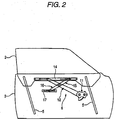
- Fig. 2 is a front elevational view illustrating a raising and lowering mechanism of a window glass of the door shown in Fig. 1 .
- Fig. 3 is a detailed front elevational view of the raising and lowering mechanism shown in Fig. 2 and illustrates an embodiment of the electric power-feeding structure In accordance with the invention.
- Fig. 4 is a plan view of the raising and lowering mechanism shown in Fig. 3 .
- Figs. 5A to 5F are cross-sectional views of an arm of the raising and flowering mechanism shown in Fig. 3 .
- Figs. 6A to 6C are schematic views illustrating the operation of the electric power-feeding structure shown in Fig. 3 in conjunction with the raising or lowering of the window glass.
- the electric power-feeding structure in accordance with this embodiment is provided in the door of the automobile, and is adapted to feed electric power to the window glass which is disposed in this door and is driven to be raised or lowered.
- the raising and lowering mechanism of the window glass will be given.
- a door panel 1 is constructed such that an outer panel 3 and an inner panel 4, which are respectively press-formed into predetermined shapes, are joined, and a required space is formed therein.
- a window glass 2 is interposed between the outer panel 3 and the inner panel 4, and is driven to be raised or lowered in a substantially vertical direction by the raising and lowering mechanism which will be described later.
- the window glass 2 is thereby made to emerge outside the door panel 1 through the gap between the outer panel 3 and the inner panel 4, which corresponds to an upper edge of the door panel 1. and dives back down into the inner space of the door panel 1.
- a pair of glass guides 5 respectively extending in the substantially vertical direction are disposed between the window glass 2 and the outer panel 3 at a predetermined interval therebetween in a forward-backward direction, i.e., a longitudinal direction of the automobile.
- the movement of the window glass 2 in the substantially vertical direction is guided with its lower end engaged with the pair of glass guides 5.
- a window regulator (raising and lowering mechanism) 6 for driving the raising and lowering of the window glass 2 is disposed in the inner space of the door panel 1.
- the window regulator 6 is a window regulator of the so-called X-arm type and has a base plate 11 which is fixed to the door panel 1, a main arm 12 which is rotatably supported by this base plate 11, and a pair of auxiliary arms 15 and 16 which are rotatably supported by this main arm 12.
- the main arm 12 is rotatably supported by the base plate 11 through a rotating shaft 13 provided at its proximal end.
- a distal end of the main arm 12 is coupled to a rail 14 fixed to a lower end portion of the window glass 2 and extending in the substantially forward-backward direction.
- the distal end of the main arm 12 is movable in the substantially forward-backward direction along the rail 14.
- One auxiliary arm 15 and the other auxiliary arm 16 are respectively located on the obverse surface side and the reverse surface side of the main arm 12, and are respectively disposed to extend In a rectilinear direction and intersect the main arm 12 substantially in the form of an X-shape. Further, the pair of auxiliary arms 15 and 16 have their respective proximal ends supported rotatably by a substantially longitudinally central portion of the main arm 12 so as to rotate mutually coaxially and integrally
- a distal end of the auxiliary arm 15 is coupled to the rail 14 fixed to the lower end portion of the window glass 2 and extending in the substantially forward-backward direction, and is movable in the substantially forward-backward direction along the rail 14.
- a distal end of the auxiliary arm 16 is coupled to a rail 17 fixed to the door panel 1 and extending in the substantially forward-backward direction in parallel with the rail 14, and is movable in the substantially forward-backward direction along the rail 17.
- a driving mechanism 18 is provided on the base plate 11.
- This driving mechanism 18 includes a driving source (which is not shown) such as a motor or a manual handle, as well as a pinion gear 18a which is rotated by the operation of this driving source. Further, a sector gear 19 is secured to the proximal end of the main arm 12 so as to rotate integrally therewith, and this sector gear 19 meshes with the pinion gear 18a of the driving mechanism 18.
- the main arm 12 when the driving source of the driving mechanism 18 is operated, the main arm 12 is rotatably driven and is swung by the meshing between the pinion gear 18a of the driving mechanism 18 and the sector gear 19. In conjunction with the swinging motion of the main arm 12, the distal end of the main arm 12 moves in the forward-backward direction along the rail 14, and moves the rail 14 in the vertical direction. As a result, the window glass 2 is raised or lowered.
- An electrical wire 21 for feeding electric power to the window glass 2 which is driven to be raised or lowered is passed by, for example, a vicinity of a hinge mechanism Installed on a vehicle body while openably supporting the door panel 1, and is introduced from the vehicle body side into the inner space of the door panel 1. Then, the electrical wire 21 is routed alongside the main arm 12 and is connected to the window glass 2. Specifically, the electrical wire 21 has its predetermined portion fixed to the base plate 11, is passed by a vicinity of the rotating shaft 13 of the main arm 12, reaches the distal end of the main arm 12 alongside one side surface of the main arm 12, is extended from the distal end of the main arm 12, and is connected to the lower end portion of the window glass 2.
- the electrical wire 21 is fixed to the main arm 12 in an entire region or a plurality of portions of the side surface of the main arm 12 alongside which the electrical wire 21 extends.
- the fixing means is not particularly limited, but it is possible to use such as an adhesive tape or clips, for example.
- the electrical wire at its portion connected to the window glass 2 may be directly fixed to the lower end portion of the window glass 2, or may be connected to the window glass 2 by being fixed to an attachment member of the window glass 2 such as the rail 14.
- the electrical wire 21 is fixed to the main arm 12 by using an adhesive tape.
- a single adhesive tape 22 is bent back substantially in a U-shape and is adhered to both obverse and reverse surfaces of the side end portion of the main arm 12, and the electrical wire 21 is tucked inside it so as to be retained.
- the electrical wire 21 is clamped and retained between two adhesive tapes 22a and 22b whose one ends are respectively adhered to the obverse surface and the reverse surface of the side end portion of the main arm 12.
- Fig. 5A a single adhesive tape 22 is bent back substantially in a U-shape and is adhered to both obverse and reverse surfaces of the side end portion of the main arm 12, and the electrical wire 21 is tucked inside it so as to be retained.
- the electrical wire 21 is clamped and retained between two adhesive tapes 22a and 22b whose one ends are respectively adhered to the obverse surface and the reverse surface of the side end portion of the main arm 12.
- Fig. 5A a single
- the electrical wire 21 is adhered and retained by an adhesive surface at one end of the single adhesive tape 22 whose other end is adhered to the obverse surface or the reverse surface of the side end portion of the main arm 12.
- the electrical wire 21 is tucked in and retained by one end of the single adhesive tape 22 whose other end is adhered to the obverse surface or the reverse surface of the side end portion of the main arm 12.
- the electrical wire 21 is fixed to the main arm by using a clip.
- a clip 23 shown in Fig. 5E has a pair of clamping pieces 23a and 23b for clamping the side end portion of the main arm 12 from its both obverse and reverse surface sides, as well as a connecting piece 23c which connects together the pair of clamping pieces 23a and 23b.
- a retaining pawl 23d is projected on that surface of one clamping piece 23a of the clip 23 which opposes the clamping piece 23b.
- the retaining pawl 23d is retainably inserted in a through hole 12a formed in the side end portion of the main arm 12, the pair of clamping pieces 23a and 23b are secured to the main arm 12 by clamping the side end portion of the main arm 12, and the electrical wire 21 is accommodated in a gap formed between the connecting piece 23c and the side surface of the main arm 12, thus allowing the clip 23 to retain the electrical wire 21.
- a clip 24 shown in Fig. 5F has a supporting piece 24a extending alongside the reverse surface of the side end portion of the main arm 12, as well as a holding frame 24b which is provided continuously from a leading end of the supporting piece 24a and is disposed adjacent to the side surface of the main arm 12.
- a retaining projection 24c is projected on the supporting piece 24a.
- the retaining projection 24c is passed through the through hole 12a, which is formed in the side end portion of the main arm 12, from the reverse surface side toward the obverse surface side, and is secured to the main arm 12 by being engaged with a peripheral edge portion on the obverse surface side of the through hole 12a, and the electrical wire 21 is accommodated inside the holding frame 24b, thus allowing the clip 24 to retain the electrical wire 21.
- Fig. 6A shows a state of the window regulator 6 when the window glass 2 is closed.
- Fig. 6B shows a state of the window regulator 6 when the window glass 2 is half open.
- Fig. 6C shows a state of the window regulator 6 when the window glass 2 is fully open.
- the main arm 12 is swung in the direction of arrow A as its proximal end is rotatably driven.
- the distal end of the main arm 12 reciprocally moves in the directions of arrows B and C along the rail 14 and lowers the rails 14.
- the window glass 2 is lowered and opened.
- the pair of auxiliary arms 15 and 16 rotate integrally while their respective distal ends are moved in the forward-backward direction along the rails 14 and 17 in conjunction with the lowering of the rail 14.
- the auxiliary arm 15 passes over the obverse surface of the main arm 12, and the auxiliary arm 16 passes over the reverse surface of the main arm 12.
- the electrical wire 21 is secured alongside the side surface of the main arm 12, so that the Interference between the electrical wire 21 and the auxiliary arms 15 and 16 is avoided. Accordingly, it is possible to narrow the gap between the main arm 12 and each of the auxiliary arms 15 and 16.
- the electrical wire is routed alongside the arm which drives the raising or lowering of the moving body, so that a major portion of the electrical wire which follows the raising and lowering of the moving body can be restricted by the arm. Accordingly, a member for restricting the movement of the electrical wire, such as a case for accommodating the electrical wire, is not separately required, so that it is possible to miniaturize and simplify the electric power-feeding structure.
- the electrical wire is routed alongside the side surface of the arm, and moves on the locus of the swinging motion of the arm in conjunction with the swinging motion of the arm.
- the electrical wire does not interfere with the moving body and other elements making up the raising and lowering mechanism of that moving body, and it is possible to narrow the gap between the arm and each of the moving body and the other elements making up the raising and lowering mechanism of that moving body, thereby making it possible to further miniaturize the electric power-feeding structure.
Description
- The present Invention relates to an electric power-feeding structure for feeding electric power to a moving body which is driven to be raised or lowered, such as a window glass of a motor vehicle.
- In the window glass of a motor vehicle, such as an automobile, electric power is fed to the window glass in which a heating wire is laid for such as the prevention of dew condensation. As an electric power-feeding structure for feeding electric power to the window glass in cases such as where the heating wire is laid in the window glass which is driven to be raised or lowered, an electric power-feeding structure shown in
Figs. 7A and 7B is conventionally known. - In the electric power-feeding structure shown in
Figs. 7A and 7B , a moving body-side connector 105 provided on awindow glass 102 which is disposed in an inner space of adoor 101 and is driven to be raised or lowered, and a door-side connector 106 provided in thedoor 101 are connected via a feeding line to feed electric power to thewindow glass 102. Looseness is produced in the feeding line in conjunction with the raising or lowering of thewindow glass 102, and in a case where the amount of looseness is large and if such a feeding line is able to move without any restriction, there is a possibility of causing a malfunction such as the feeding line becoming bitten by a raising and lowering mechanism of thewindow glass 102. For this reason, the looseness produced in the feeding line is restricted by an excess-length absorbing device 103 disposed in the inner space of thedoor 101. - The excess-
length absorbing device 103 is so configured that the feeding line is accommodated in acase 111 in such a manner as to be turned back in a U-shape along the raising or lowering direction of thewindow glass 102. On end portion side (indicated byreference numeral 104 in the drawings) of the feeding line is held by a slidingmember 112 engaged with thecase 111 movably in the raising or lowering direction of thewindow glass 102, is led out from thecase 111, and is connected to the moving body-side connector 105. The slidingmember 112 moves vertically while being accompanied by the deformation of the feeding line turned back in the U-shape inside thecase 111, and thefeeding line 104 follows the raising or lowering of thewindow glass 102. Although looseness is produced in the feeding line within thecase 111 in conjunction with the vertical movement of thesliding member 112, its movement is restricted to within thecase 111, and the biting by the raising and lowering mechanism of thewindow glass 102 is prevented (refer to patent document 1).
[Patent Document 1]JP-A-2005-57828 - In the electric power-feeding structure disclosed in the
patent document 1, the feeding line is accommodated in thecase 111 in such a manner as to be turned back in the U-shape along the raising or lowering direction of thewindow glass 102 to cope with the raising or lowering of thewindow glass 102. In this case, an excess length by at least more than half the stroke of thewindow glass 102 is required for the feeding line, and the amount of looseness produced in the feeding line in conjunction with the raising or lowering of thewindow glass 102 is also relatively large. For this reason, thecase 111 for accommodating the feeding line is necessary, and thecase 111 becomes large in size. It is difficult to further secure an accommodation space for thecase 111 in the inner space of thedoor 101 in which thewindow glass 102 and its raising and lowering mechanism are accommodated -
JP-A-61060345 claim 1. - The present Invention has been devised in view of the above-described circumstances, and its object is to provide a miniaturized and simplified electric power-feeding structure for feeding electric power to a moving body which is driven to be raised or lowered.
- To attain the above object, in accordance with an aspect of the invention there is provided an electric power-feeding structure according to
claim 1. - In the electric power-feeding structure in accordance with the invention, the electrical wire is routed alongside the arm which drives the raising or lowering of the moving body, so that a major portion of the electrical wire which follows the raising and lowering of the moving body can be restricted by the arm. Accordingly, a member for restricting the movement of the electrical wire, such as a case for accommodating the electrical wire, is not separately required, so that it is possible to miniaturize and simplify the electric power-feeding structure. In addition, the electrical wire is routed alongside the side surface of the arm, and moves on the locus of the swinging motion of the arm in conjunction with the swinging motion of the arm. Accordingly, the electrical wire does not interfere with the moving body and other elements making up the raising and lowering mechanism of that moving body, and it is possible to narrow the gap between the arm and each of the moving body and the other elements making up the raising and lowering mechanism of that moving body, thereby making it possible to further miniaturize the electric power-feeding structure.
- The above objects and advantages of the present invention will become more apparent by describing in detail preferred exemplary embodiments thereof with reference to the accompanying drawings, wherein like reference numerals designate like or corresponding parts throughout the several views, and wherein:
-
Fig. 1 is a cross-sectional view of a door of an automobile to which the electric power-feeding structure in accordance with the invention is applied; -
Fig. 2 is a front elevational view illustrating a raising and lowering mechanism of a window glass of the door shown inFig. 1 ; -
Fig. 3 is a detailed front elevational view of the raising and lowering mechanism shown inFig. 2 and illustrates an embodiment of the electric power-feeding structure in accordance with the invention; -
Fig. 4 is a plan view of the raising and lowering mechanism shown inFig. 3 ; -
Figs. 5A to 5F are cross-sectional views of an arm of the raising and lowering mechanism shown inFig. 3 ; -
Figs. 6A to 6C are schematic views illustrating the operation of the electric power-feeding structure shown inFig. 3 in conjunction with the raising or lowering of the window glass; and -
Figs. 7A and 7B are cross-sectional views of a door of an automobile illustrating a conventional electric power-feeding structure. - Referring now to the accompanying drawings, a description will be given of a preferred embodiment of an electric power-feeding structure in accordance with the invention.
-
Fig. 1 is a cross-sectional view of a door of an automobile to which the electric power-feeding structure in accordance with the invention is applied.Fig. 2 is a front elevational view illustrating a raising and lowering mechanism of a window glass of the door shown inFig. 1 .Fig. 3 is a detailed front elevational view of the raising and lowering mechanism shown inFig. 2 and illustrates an embodiment of the electric power-feeding structure In accordance with the invention.Fig. 4 is a plan view of the raising and lowering mechanism shown inFig. 3 .Figs. 5A to 5F are cross-sectional views of an arm of the raising and flowering mechanism shown inFig. 3 .Figs. 6A to 6C are schematic views illustrating the operation of the electric power-feeding structure shown inFig. 3 in conjunction with the raising or lowering of the window glass. - As shown in
Figs. 1 and2 , the electric power-feeding structure in accordance with this embodiment is provided in the door of the automobile, and is adapted to feed electric power to the window glass which is disposed in this door and is driven to be raised or lowered. Hereafter, a description will be given of the raising and lowering mechanism of the window glass. - A
door panel 1 is constructed such that anouter panel 3 and an inner panel 4, which are respectively press-formed into predetermined shapes, are joined, and a required space is formed therein. - A
window glass 2 is interposed between theouter panel 3 and the inner panel 4, and is driven to be raised or lowered in a substantially vertical direction by the raising and lowering mechanism which will be described later. Thewindow glass 2 is thereby made to emerge outside thedoor panel 1 through the gap between theouter panel 3 and the inner panel 4, which corresponds to an upper edge of thedoor panel 1. and dives back down into the inner space of thedoor panel 1. - A pair of
glass guides 5 respectively extending in the substantially vertical direction are disposed between thewindow glass 2 and theouter panel 3 at a predetermined interval therebetween in a forward-backward direction, i.e., a longitudinal direction of the automobile. The movement of thewindow glass 2 in the substantially vertical direction is guided with its lower end engaged with the pair ofglass guides 5. - Further, a window regulator (raising and lowering mechanism) 6 for driving the raising and lowering of the
window glass 2 is disposed in the inner space of thedoor panel 1. - Referring further to
Figs. 3 and4 , thewindow regulator 6 is a window regulator of the so-called X-arm type and has abase plate 11 which is fixed to thedoor panel 1, amain arm 12 which is rotatably supported by thisbase plate 11, and a pair ofauxiliary arms main arm 12. - The
main arm 12 is rotatably supported by thebase plate 11 through a rotatingshaft 13 provided at its proximal end. A distal end of themain arm 12 is coupled to arail 14 fixed to a lower end portion of thewindow glass 2 and extending in the substantially forward-backward direction. The distal end of themain arm 12 is movable in the substantially forward-backward direction along therail 14. - One
auxiliary arm 15 and the otherauxiliary arm 16 are respectively located on the obverse surface side and the reverse surface side of themain arm 12, and are respectively disposed to extend In a rectilinear direction and intersect themain arm 12 substantially in the form of an X-shape. Further, the pair ofauxiliary arms main arm 12 so as to rotate mutually coaxially and integrally - In the same way as the distal end of the
main arm 12, a distal end of theauxiliary arm 15 is coupled to therail 14 fixed to the lower end portion of thewindow glass 2 and extending in the substantially forward-backward direction, and is movable in the substantially forward-backward direction along therail 14. Meanwhile, a distal end of theauxiliary arm 16 is coupled to arail 17 fixed to thedoor panel 1 and extending in the substantially forward-backward direction in parallel with therail 14, and is movable in the substantially forward-backward direction along therail 17. - A
driving mechanism 18 is provided on thebase plate 11. Thisdriving mechanism 18 includes a driving source (which is not shown) such as a motor or a manual handle, as well as apinion gear 18a which is rotated by the operation of this driving source. Further, asector gear 19 is secured to the proximal end of themain arm 12 so as to rotate integrally therewith, and thissector gear 19 meshes with thepinion gear 18a of thedriving mechanism 18. - In the above-described configuration, when the driving source of the
driving mechanism 18 is operated, themain arm 12 is rotatably driven and is swung by the meshing between thepinion gear 18a of thedriving mechanism 18 and thesector gear 19. In conjunction with the swinging motion of themain arm 12, the distal end of themain arm 12 moves in the forward-backward direction along therail 14, and moves therail 14 in the vertical direction. As a result, thewindow glass 2 is raised or lowered. - In a state In which the pair of
auxiliary arms rail 14 which is vertically moved and therail 17 which is fixed to thedoor panel 1, the pair ofauxiliary arms rails rail 14, allowing the posture of therail 14 to be maintained. As a result, thewindow glass 2 is raised or lowered stably. - An
electrical wire 21 for feeding electric power to thewindow glass 2 which is driven to be raised or lowered is passed by, for example, a vicinity of a hinge mechanism Installed on a vehicle body while openably supporting thedoor panel 1, and is introduced from the vehicle body side into the inner space of thedoor panel 1. Then, theelectrical wire 21 is routed alongside themain arm 12 and is connected to thewindow glass 2. Specifically, theelectrical wire 21 has its predetermined portion fixed to thebase plate 11, is passed by a vicinity of therotating shaft 13 of themain arm 12, reaches the distal end of themain arm 12 alongside one side surface of themain arm 12, is extended from the distal end of themain arm 12, and is connected to the lower end portion of thewindow glass 2. - The
electrical wire 21 is fixed to themain arm 12 in an entire region or a plurality of portions of the side surface of themain arm 12 alongside which theelectrical wire 21 extends. The fixing means is not particularly limited, but it is possible to use such as an adhesive tape or clips, for example. The electrical wire at its portion connected to thewindow glass 2 may be directly fixed to the lower end portion of thewindow glass 2, or may be connected to thewindow glass 2 by being fixed to an attachment member of thewindow glass 2 such as therail 14. - In the examples shown in
Figs. 5A to 5D , theelectrical wire 21 is fixed to themain arm 12 by using an adhesive tape. InFig. 5A , a singleadhesive tape 22 is bent back substantially in a U-shape and is adhered to both obverse and reverse surfaces of the side end portion of themain arm 12, and theelectrical wire 21 is tucked inside it so as to be retained. InFig. 5B , theelectrical wire 21 is clamped and retained between twoadhesive tapes main arm 12. InFig. 5C , theelectrical wire 21 is adhered and retained by an adhesive surface at one end of the singleadhesive tape 22 whose other end is adhered to the obverse surface or the reverse surface of the side end portion of themain arm 12. InFig. 5D , theelectrical wire 21 is tucked in and retained by one end of the singleadhesive tape 22 whose other end is adhered to the obverse surface or the reverse surface of the side end portion of themain arm 12. - In addition, in the examples shown in
Figs. 5E and 5F , theelectrical wire 21 is fixed to the main arm by using a clip. Aclip 23 shown inFig. 5E has a pair of clampingpieces main arm 12 from its both obverse and reverse surface sides, as well as a connectingpiece 23c which connects together the pair of clampingpieces pawl 23d is projected on that surface of oneclamping piece 23a of theclip 23 which opposes theclamping piece 23b. The retainingpawl 23d is retainably inserted in a throughhole 12a formed in the side end portion of themain arm 12, the pair of clampingpieces main arm 12 by clamping the side end portion of themain arm 12, and theelectrical wire 21 is accommodated in a gap formed between the connectingpiece 23c and the side surface of themain arm 12, thus allowing theclip 23 to retain theelectrical wire 21. Aclip 24 shown inFig. 5F has a supportingpiece 24a extending alongside the reverse surface of the side end portion of themain arm 12, as well as a holdingframe 24b which is provided continuously from a leading end of the supportingpiece 24a and is disposed adjacent to the side surface of themain arm 12. A retainingprojection 24c is projected on the supportingpiece 24a. The retainingprojection 24c is passed through the throughhole 12a, which is formed in the side end portion of themain arm 12, from the reverse surface side toward the obverse surface side, and is secured to themain arm 12 by being engaged with a peripheral edge portion on the obverse surface side of the throughhole 12a, and theelectrical wire 21 is accommodated inside the holdingframe 24b, thus allowing theclip 24 to retain theelectrical wire 21. - Next, referring to
Figs. 6A to 6C , a description will be given of the operation of the electric power-feeding structure in accordance with this embodiment.Fig. 6A shows a state of thewindow regulator 6 when thewindow glass 2 is closed.Fig. 6B shows a state of thewindow regulator 6 when thewindow glass 2 is half open.Fig. 6C shows a state of thewindow regulator 6 when thewindow glass 2 is fully open. - From the state of the
window regulator 6 shown inFig. 6A , themain arm 12 is swung in the direction of arrow A as its proximal end is rotatably driven. In conjunction with the swinging motion of themain arm 12 in the direction of the arrow A, as sequentially shown inFigs. 6B and 6C , the distal end of themain arm 12 reciprocally moves in the directions of arrows B and C along therail 14 and lowers therails 14. As a result, thewindow glass 2 is lowered and opened. - Further, in the state in which the pair of
auxiliary arms rail 14 which is lowered and therail 17 which is fixed to thedoor panel 1, the pair ofauxiliary arms rails rail 14. In that process, theauxiliary arm 15 passes over the obverse surface of themain arm 12, and theauxiliary arm 16 passes over the reverse surface of themain arm 12. However, theelectrical wire 21 is secured alongside the side surface of themain arm 12, so that the Interference between theelectrical wire 21 and theauxiliary arms main arm 12 and each of theauxiliary arms - As described above, according to the electric power-feeding structure of this embodiment, the electrical wire is routed alongside the arm which drives the raising or lowering of the moving body, so that a major portion of the electrical wire which follows the raising and lowering of the moving body can be restricted by the arm. Accordingly, a member for restricting the movement of the electrical wire, such as a case for accommodating the electrical wire, is not separately required, so that it is possible to miniaturize and simplify the electric power-feeding structure. In addition, the electrical wire is routed alongside the side surface of the arm, and moves on the locus of the swinging motion of the arm in conjunction with the swinging motion of the arm. Accordingly, the electrical wire does not interfere with the moving body and other elements making up the raising and lowering mechanism of that moving body, and it is possible to narrow the gap between the arm and each of the moving body and the other elements making up the raising and lowering mechanism of that moving body, thereby making it possible to further miniaturize the electric power-feeding structure.
- It should be noted that the invention is not limited to the above-described embodiment, and modifications, improvements, and the like are possible, as required. In addition, the shapes, dimensions, numerical values, forms, numbers, places of disposition, and the like of the respective constituent elements in the above-described embodiment are arbitrary and are not limited Insofar as they are capable of attaining the invention.
- For example, although in the above-described embodiment a description has been given of the example in which the invention is applied to the X-arm
type window regulator 6 having themain arm 12 and the pair ofauxiliary arms main arm 12.
Claims (6)
- An electric power-feeding structure for feeding electric power to a moving body (2) which is driven to be raised or lowered, comprising:an arm (12) having an obverse surface, a reverse surface, opposite sides surfaces, a distal end connected to the moving body (2) movably in a direction perpendicular to a raising or lowering direction of the moving body (2) and a proximal end adapted to be rotatably driven so as to swing, to thereby control the raising or lowering of the moving body (2),characterized in thatan electrical wire (21) is routed alongside one of the side surfaces of the arm (12), and one end of the electrical wire (21) extending from the distal end of the arm (12) is connected to the moving body (2) to feed electric power to the moving body (2).
- The electric power-feeding structure according to claim 1, wherein the arm (12) includes a main arm (12) having a drive mechanism to rotate the main arm (12), and an auxiliary arm (15, 16) rotated in accordance with a rotation of the main arm (12), and
wherein the electrical wire (21) is routed alongside one of the side surfaces of the main arm (12). - The electric power-feeding structure according to claim 1, further comprising: a fixing unit (22, 23, 24) which is attached to the arm (12) to fix the electrical wire (21) to the arm (12).
- The electric power-feeding structure according to claim 3, wherein the fixing unit (22, 23, 24) accommodates the electrical wire (21) therein to fix the electrical wire (21) to the arm (12).
- The electric power-feeding structure according to claim 4, wherein the fixing unit (23, 24) includes a first engaging portion (23d, 24c), and wherein the arm (12) includes a second engaging portion (12a) engaged with the first engaging portion (23d, 24c).
- The electric power-feeding structure according to claim 1, wherein the electrical wire (21) is routed alongside the one of the side surfaces of the arm (12) from the distal end to the proximal end of the arm (12).
Applications Claiming Priority (1)
| Application Number | Priority Date | Filing Date | Title |
|---|---|---|---|
| JP2007234119A JP5052267B2 (en) | 2007-09-10 | 2007-09-10 | Feeding structure |
Publications (2)
| Publication Number | Publication Date |
|---|---|
| EP2034580A1 EP2034580A1 (en) | 2009-03-11 |
| EP2034580B1 true EP2034580B1 (en) | 2016-06-29 |
Family
ID=40149629
Family Applications (1)
| Application Number | Title | Priority Date | Filing Date |
|---|---|---|---|
| EP08015773.8A Active EP2034580B1 (en) | 2007-09-10 | 2008-09-08 | Electric power-feeding structure |
Country Status (5)
| Country | Link |
|---|---|
| US (1) | US8125100B2 (en) |
| EP (1) | EP2034580B1 (en) |
| JP (1) | JP5052267B2 (en) |
| CN (1) | CN101388534B (en) |
| AU (1) | AU2008212082B2 (en) |
Families Citing this family (3)
| Publication number | Priority date | Publication date | Assignee | Title |
|---|---|---|---|---|
| JP5743504B2 (en) * | 2010-11-30 | 2015-07-01 | シロキ工業株式会社 | Window regulator |
| CN107335838A (en) * | 2017-07-31 | 2017-11-10 | 湖州华通研磨制造有限公司 | One kind machining uses multifunctional hole-drilling machine |
| KR20220104252A (en) * | 2019-12-05 | 2022-07-26 | 가부시키가이샤나가키세이키 | Wire Grippers and Wire Cutting Tools |
Family Cites Families (21)
| Publication number | Priority date | Publication date | Assignee | Title |
|---|---|---|---|---|
| US3724133A (en) * | 1970-04-03 | 1973-04-03 | Nippon Denso Co | Means for opening and closing a window assembly of a vehicle |
| US3782037A (en) * | 1972-07-31 | 1974-01-01 | Hancock Ind Inc | Cam operated two-stage window regulator |
| US3816962A (en) * | 1973-03-07 | 1974-06-18 | Ford Motor Co | Window regulator mechanism |
| JPS6160345A (en) * | 1984-08-31 | 1986-03-28 | Hino Motors Ltd | Wiring structure of feed wire for defogger heating wire |
| US4823507A (en) * | 1987-06-24 | 1989-04-25 | General Motors Corporation | Window regulator mechanism for frameless windows |
| US4939867A (en) * | 1989-07-31 | 1990-07-10 | Amso Co., Ltd. | Power supplying system for self-driving closure device |
| US5255470A (en) * | 1992-06-23 | 1993-10-26 | Gencorp Inc. | Vehicle door glass regulator |
| US5201144A (en) * | 1992-09-14 | 1993-04-13 | General Motors Corporation | Eccentrically located aperture in a cam slider for window regulator |
| JP3931537B2 (en) * | 2000-06-28 | 2007-06-20 | アイシン精機株式会社 | Window door opening and closing device for vehicle sliding door |
| JP3483862B2 (en) * | 2001-04-17 | 2004-01-06 | ファナック株式会社 | Robot cable handling structure |
| KR20030008974A (en) * | 2001-07-21 | 2003-01-29 | 현대자동차주식회사 | Power window regulator for vehicle |
| JP2003214027A (en) * | 2002-01-28 | 2003-07-30 | Fuji Heavy Ind Ltd | Window regulator |
| FR2853870B1 (en) * | 2003-04-18 | 2006-05-19 | Arvinmeritor Light Vehicle Sys | VEHICLE DOOR |
| JP4220325B2 (en) | 2003-08-04 | 2009-02-04 | 三菱電線工業株式会社 | Wire surplus length absorber |
| JP2005065451A (en) * | 2003-08-19 | 2005-03-10 | Komatsu Ltd | Cable processor and work transfer device using the cable processor |
| KR100528515B1 (en) * | 2003-09-16 | 2005-11-15 | 현대자동차주식회사 | Regulator assembly of door glass for automobile |
| US7224136B2 (en) * | 2005-06-28 | 2007-05-29 | Asmo Co., Ltd. | Control apparatus for closure device |
| JP4668784B2 (en) * | 2005-12-27 | 2011-04-13 | 矢崎総業株式会社 | Link-type movable harness wiring structure |
| JP4800030B2 (en) * | 2005-12-27 | 2011-10-26 | 本田技研工業株式会社 | Window glass lifting device |
| JP5052268B2 (en) * | 2007-09-10 | 2012-10-17 | 矢崎総業株式会社 | Feeding structure |
| JP5063266B2 (en) * | 2007-09-10 | 2012-10-31 | 矢崎総業株式会社 | Feeding structure |
-
2007
- 2007-09-10 JP JP2007234119A patent/JP5052267B2/en active Active
-
2008
- 2008-09-08 EP EP08015773.8A patent/EP2034580B1/en active Active
- 2008-09-09 US US12/207,295 patent/US8125100B2/en active Active
- 2008-09-09 CN CN2008102155711A patent/CN101388534B/en active Active
- 2008-09-09 AU AU2008212082A patent/AU2008212082B2/en not_active Ceased
Also Published As
| Publication number | Publication date |
|---|---|
| JP5052267B2 (en) | 2012-10-17 |
| AU2008212082B2 (en) | 2012-12-13 |
| EP2034580A1 (en) | 2009-03-11 |
| CN101388534A (en) | 2009-03-18 |
| AU2008212082A1 (en) | 2009-03-26 |
| JP2009071892A (en) | 2009-04-02 |
| CN101388534B (en) | 2012-01-04 |
| US8125100B2 (en) | 2012-02-28 |
| US20090066155A1 (en) | 2009-03-12 |
Similar Documents
| Publication | Publication Date | Title |
|---|---|---|
| US5784833A (en) | Silding window with motor-driven regulator | |
| EP2034581B1 (en) | Electric power-feeding structure | |
| US20110120019A1 (en) | Vehicle Window Regulator Having a Floating Window Carrier | |
| US10287815B2 (en) | Door operator | |
| EP2520450B1 (en) | Window shade device for vehicles | |
| EP2034580B1 (en) | Electric power-feeding structure | |
| US20130000941A1 (en) | Power feeding wiring structure | |
| JP3813093B2 (en) | Automatic switchgear for vehicles | |
| US8004108B2 (en) | Electric power-feeding structure with arm and electric wire for feeding electric power to moving body | |
| US7571958B2 (en) | Sunshade panel apparatus | |
| JP4669177B2 (en) | Automobile sliding door opening movement restriction device | |
| JP4018321B2 (en) | Opening / closing member driving device | |
| JP5052266B2 (en) | Feeding structure | |
| US20070056218A1 (en) | Window lifter for a motor vehicle | |
| JP5068201B2 (en) | Feeding structure | |
| JP5075604B2 (en) | Vehicle door opening and closing device | |
| JP3734684B2 (en) | VEHICLE DOOR HAVING WIRE-TYPE WINDOW REGULATOR AND METHOD OF ASSEMBLING THE SAME | |
| WO2000023293A1 (en) | Door and door module for vehicle | |
| JPH04155083A (en) | Power window device of vehicle's door | |
| EP3074584B1 (en) | A window regulator mechanism | |
| JP5052273B2 (en) | Feeding structure | |
| JP2009071890A (en) | Electric power-feeding structure | |
| JP2555489Y2 (en) | Geared wire support structure for geared wire window regulator | |
| JP2001349132A (en) | Arm-type window regulator | |
| JPS6374719A (en) | Door structure for automobile |
Legal Events
| Date | Code | Title | Description |
|---|---|---|---|
| PUAI | Public reference made under article 153(3) epc to a published international application that has entered the european phase |
Free format text: ORIGINAL CODE: 0009012 |
|
| AK | Designated contracting states |
Kind code of ref document: A1 Designated state(s): AT BE BG CH CY CZ DE DK EE ES FI FR GB GR HR HU IE IS IT LI LT LU LV MC MT NL NO PL PT RO SE SI SK TR |
|
| AX | Request for extension of the european patent |
Extension state: AL BA MK RS |
|
| 17P | Request for examination filed |
Effective date: 20090730 |
|
| AKX | Designation fees paid |
Designated state(s): DE FR GB IT |
|
| 17Q | First examination report despatched |
Effective date: 20150824 |
|
| GRAP | Despatch of communication of intention to grant a patent |
Free format text: ORIGINAL CODE: EPIDOSNIGR1 |
|
| INTG | Intention to grant announced |
Effective date: 20160307 |
|
| GRAS | Grant fee paid |
Free format text: ORIGINAL CODE: EPIDOSNIGR3 |
|
| GRAA | (expected) grant |
Free format text: ORIGINAL CODE: 0009210 |
|
| AK | Designated contracting states |
Kind code of ref document: B1 Designated state(s): DE FR GB IT |
|
| REG | Reference to a national code |
Ref country code: GB Ref legal event code: FG4D |
|
| REG | Reference to a national code |
Ref country code: DE Ref legal event code: R096 Ref document number: 602008044853 Country of ref document: DE |
|
| PG25 | Lapsed in a contracting state [announced via postgrant information from national office to epo] |
Ref country code: IT Free format text: LAPSE BECAUSE OF FAILURE TO SUBMIT A TRANSLATION OF THE DESCRIPTION OR TO PAY THE FEE WITHIN THE PRESCRIBED TIME-LIMIT Effective date: 20160629 |
|
| REG | Reference to a national code |
Ref country code: DE Ref legal event code: R097 Ref document number: 602008044853 Country of ref document: DE |
|
| PLBE | No opposition filed within time limit |
Free format text: ORIGINAL CODE: 0009261 |
|
| STAA | Information on the status of an ep patent application or granted ep patent |
Free format text: STATUS: NO OPPOSITION FILED WITHIN TIME LIMIT |
|
| GBPC | Gb: european patent ceased through non-payment of renewal fee |
Effective date: 20160929 |
|
| 26N | No opposition filed |
Effective date: 20170330 |
|
| STAA | Information on the status of an ep patent application or granted ep patent |
Free format text: STATUS: NO OPPOSITION FILED WITHIN TIME LIMIT |
|
| REG | Reference to a national code |
Ref country code: FR Ref legal event code: ST Effective date: 20170531 |
|
| PG25 | Lapsed in a contracting state [announced via postgrant information from national office to epo] |
Ref country code: FR Free format text: LAPSE BECAUSE OF NON-PAYMENT OF DUE FEES Effective date: 20160930 Ref country code: GB Free format text: LAPSE BECAUSE OF NON-PAYMENT OF DUE FEES Effective date: 20160929 |
|
| PGFP | Annual fee paid to national office [announced via postgrant information from national office to epo] |
Ref country code: DE Payment date: 20230802 Year of fee payment: 16 |