EP2034465A2 - Electronic device - Google Patents
Electronic device Download PDFInfo
- Publication number
- EP2034465A2 EP2034465A2 EP08015491A EP08015491A EP2034465A2 EP 2034465 A2 EP2034465 A2 EP 2034465A2 EP 08015491 A EP08015491 A EP 08015491A EP 08015491 A EP08015491 A EP 08015491A EP 2034465 A2 EP2034465 A2 EP 2034465A2
- Authority
- EP
- European Patent Office
- Prior art keywords
- control
- electronic device
- component
- keys
- assignment
- Prior art date
- Legal status (The legal status is an assumption and is not a legal conclusion. Google has not performed a legal analysis and makes no representation as to the accuracy of the status listed.)
- Withdrawn
Links
- 230000006870 function Effects 0.000 claims description 43
- 230000003287 optical effect Effects 0.000 description 6
- 230000005236 sound signal Effects 0.000 description 4
- 238000006243 chemical reaction Methods 0.000 description 2
- 238000010586 diagram Methods 0.000 description 2
- 239000004973 liquid crystal related substance Substances 0.000 description 2
- 230000009977 dual effect Effects 0.000 description 1
- 238000004519 manufacturing process Methods 0.000 description 1
- 238000012986 modification Methods 0.000 description 1
- 230000004048 modification Effects 0.000 description 1
Images
Classifications
-
- G—PHYSICS
- G08—SIGNALLING
- G08C—TRANSMISSION SYSTEMS FOR MEASURED VALUES, CONTROL OR SIMILAR SIGNALS
- G08C17/00—Arrangements for transmitting signals characterised by the use of a wireless electrical link
-
- G—PHYSICS
- G08—SIGNALLING
- G08C—TRANSMISSION SYSTEMS FOR MEASURED VALUES, CONTROL OR SIMILAR SIGNALS
- G08C2201/00—Transmission systems of control signals via wireless link
- G08C2201/40—Remote control systems using repeaters, converters, gateways
Definitions
- the present invention generally relates to an electronic device. More specifically, the present invention relates to an electronic device that is connected to an external electronic device via a control cable.
- the television receivers are used with DVD recorders, DVD recorders with built-in hard disks, and other such information recording and reproduction devices. Between the television receivers and the information recording and reproduction devices, large quantities of video and audio data are sent and received. Thus, an HDMI (High Definition Multimedia Interface) interface circuit has been used to connect between the television receivers and the information recording and reproduction devices.
- HDMI High Definition Multimedia Interface
- the HDMI is an interface for transmitting various kinds of data, including video and audio data, between a sending side, such as a television receiver or a projector, and a receiving side, such as a DVD recorder or a DVD recorder with a built-in hard disk.
- a CEC (Consumer Electronics Control) function of the HDMI allows power of the information recording and reproduction device to be switched on when power of the television receiver is switched on, for example.
- the electronic devices can be connected via an HDMI cable to another electronic device that meets the HDMI standards.
- remote control a single remote control transmitter
- the remote control that comes with a television set made by company A is equipped with a dedicated switch group for controlling the television set made by the company A.
- the remote control is equipped with an other device switch group for controlling another device (such as a DVD player made by company B).
- a control code assigned to a function corresponding to the switch is transmitted as a remote control signal.
- the remote control signal is received by a remote control receiver of the television set made by company A.
- a CPU of the television set made by company A recognizes the control code received through the remote control receiver as a control code for controlling the DVD player made by the company B
- the received control code is converted into a corresponding common control code based on a conversion table.
- the converted common control code is transmitted through an AV cable to the DVD player made by company B.
- a CPU of the DVD player made by company B converts the common control code received from the television set made by company A into a company B-specific code based on a conversion table. As a result, the DVD player is operated based on the converted company B-specific code.
- control codes for other devices are pre-assigned to the switches of the other device switch group provided to the remote control. Therefore, the user has to remember which control code is assigned to which switch. Also, users use remote controls in different ways. Thus, some switches used often and others less often.
- the control codes are pre-assigned to each of the switches of the other device switch group, depending on the user, the control codes that are not used very often are assigned to switches in easy-to-operate locations, and the control codes that are used frequently are assigned to switches in difficult-to-operate locations.
- the other device switch group is provided separately from the dedicated switch group, there are more switches on the remote control.
- the remote control itself is required to be smaller, the size of the switches themselves ends up being smaller, or the switches have to be positioned more closely together. As a result, it becomes more difficult for the user to operate the remote control.
- the present invention is conceived in light of the above-mentioned problems.
- One object of the present invention is to provide an electric device that makes it easier to operate an external electronic device connected to the electric device with a remote control of the electric device.
- an electronic device is electrically connected to an external electronic device.
- the electronic device includes an assignment component, a memory component and a control component.
- the assignment component is configured to assign control codes that control operations of the external electronic device to a plurality of control keys of a remote control to generate assignment information indicating corresponding relationship between the control codes and the control keys of the remote control.
- the memory component is configured to store the assignment information generated by the assignment component.
- the control component is configured to control the external electronic device based on the assignment information stored in the memory component when the control component receives an operation signal indicating that one of the control keys of the remote control is operated.
- the electric device of the present invention it is possible to provide an electric device that makes it easier to operate an external electronic device connected to the electric device with a remote control of the electric device.
- FIG. 1 is a block diagram illustrating a television receiver in accordance with a first embodiment of the present invention
- FIG. 2 is a plan view of a remote control of the television receiver illustrated in FIG. 1 ;
- FIG. 3 is a screen shot of a control code assignment setting screen
- FIG. 4 is a screen shot of a control key assignment information displayed on a program screen
- FIG. 5 is a plan view of a remote control of a television receiver in accordance with a second embodiment of the present invention.
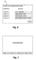
- FIG. 6 is a screen shot of a control code assignment setting screen
- FIG. 7 is a screen shot of a control key assignment information displayed on a program screen.
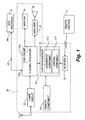
- FIG. 1 is a block diagram of a television receiver (e.g., electronic device).
- the television receiver receives digital broadcasts.
- the television receiver includes a TV control system 20 housed in a casing of the television receiver.
- the TV control system 20 further includes a TV microprocessor 21, a tuner circuit 22, TV signal processor (e.g., television receiving component) 24, a receiver 25, a monitor 26, an amplifier 27, a internal speaker 28 and a memory component 29.
- the TV microprocessor 21 controls the entire TV control system 20.
- the TV microprocessor 21 includes an assignment component 21 a and a control component 21b.
- the assignment component 21 a assigns control codes to first to fourth control keys 41 f to 41i of a remote control transmitter (hereinafter referred to as "remote control") 41 shown in FIG.
- remote control remote control transmitter
- the control codes are operation commands that control operations of a DVD recorder (e.g., external electronic device) 30 externally connected to the television receiver.
- the control key assignment information indicates corresponding relationship between the control codes and the first to fourth control keys 41f to 41i of the remote control 41.
- the control component 21 b controls the DVD recorder 30 based on the control key assignment information.
- the tuner circuit 22 receives digital television signals of the digital broadcasts. An output of the tuner circuit 22 is connected to the TV signal processor 24.
- the TV signal processor 24 performs signal processing of the digital broadcasts. Specifically, the TV signal processor 24 performs video and audio signal processing of the digital broadcasts.
- An output of the TV signal processor 24 is connected to the monitor 26.
- the monitor includes a display device, such as a CRT, a liquid crystal panel, and the like.
- the output of the TV signal processor 24 is also connected to the internal speaker 28 via the amplifier 27.
- the TV signal processor 24 has an OSD circuit (e.g., display component) 24a and an HDMI (High Definition Multimedia Interface) terminal 24b.
- the OSD circuit 24a displays various setting screens on the monitor 26. Specifically, the OSD circuit 24a displays a menu screen for performing various settings of the television receiver, a channel tuning screen when a channel is changed, or a control key assignment setting screen (e.g., assignment setting screen) 100.
- the HDMI terminal 24b is an input/output terminal for digital signals (digital video signal, digital audio signal or digital control signal) that meets HDMI standards.
- the HDMI terminal 24b is connected via an HDMI cable 40 to an HDMI terminal 30a of the DVD recorder 30 that meets HDMI standards.
- the HDMI terminal 24b transmits the control codes to the DVD recorder 30.
- the DVD recorder 30 is electrically and externally connected to the television receiver.
- the TV signal processor 24 decodes the digital television signals received via the tuner circuit 22 into the digital video and audio signals.
- the TV signal processor 24 also displays the video signal on the monitor 26 and outputs the audio signal from the internal speaker 28.
- the control component 21 b of the TV microprocessor 21 controls the TV signal processor 24.
- the receiver 25 receives various operation signals from the remote control 41 of the television receiver.
- the TV microprocessor 21 is connected to an output of the receiver 25.
- the control component 21b of the TV microprocessor 21 performs operational control of the TV control system 20, setting of the control codes of the DVD recorder 30 and control processing of the DVD recorder 30 based on the various operation signals sent from the remote control 41.
- the memory component 29 is connected to the TV microprocessor 21.
- the memory component 29 stores a channel table, processing programs, the control codes, the control key assignment information, etc.
- the channel table is a table information in which various channels have been set by auto-preset or the like through operation of the remote control 41.
- the processing programs is programs for setting connection settings (such as video and audio settings) when the television receiver is connected via the HDMI cable 40 to the DVD recorder 30.
- the control codes are operation command for the DVD recorder 30. Specifically, the control codes include CEC (Consumer Electric Control) messages defined by the HDMI standards.
- the control key assignment information is set by the user by operating the remote control 41.
- the control key assignment information is set sequentially from the control code assignment setting screen 100 shown in FIG. 3 by operating the remote control 41.
- the control key assignment setting screen 100 prompts to input an assignment of the control codes to the control keys.
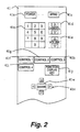
- FIG. 2 is a plan view of the remote control 41.
- the remote control 41 has a power key 41a, a menu key 41 b, number keys 41 c, channel up and down keys 41 d, volume up and down keys 41e, a plurality of first to fourth control keys (e.g., control keys) 41 f to 41 i, a function display key (e.g., assignment information display key) 41j, directional keys 41 v, an enter key 41w, and so forth.
- first to fourth control keys 41 f to 41i is keys for controlling the DVD recorder 30 (four in this example, but the number is not limited to four).
- the function display key 41j is a key for displaying the control key assignment information set to the first to fourth control keys 41 f to 41 i on the monitor 26.
- the enter key 41 w is disposed in the middle of the directional keys 41v.
- the user can freely set (assign) the control codes for the DVD recorder 30 to the first to fourth control keys 41f to 41i. However, even if the user has not set any control codes, default control codes are preset to the first to fourth control keys 41f to 41 i. Therefore, the user can use the first to fourth control keys 41 f to 41i with default functions corresponding to the default control codes without assigning the control codes to the first to fourth control keys 41 f to 41i.
- the power of the television receiver is turned on. If the user operates the menu key 41 b on the remote control 41, then the control component 21 b of the TV microprocessor 21 receives an operation signal from the remote control 41 via the receiver 25. Then, the TV signal processor 24 receives a command from the control component 21b of the TV microprocessor 21 to display a menu screen and the OSD circuit 24a displays the menu screen on the monitor 26. The user selects a control key setting category from among displayed lists of the menu by moving a cursor on the menu screen of the monitor 26 to the control key setting category with the directional keys 41v, and pressing the enter key 41 w.
- control component 21 b of the TV microprocessor 21 read the control code assignment setting screen 100 for assigning the control codes (functions) to the first to fourth control keys 41 f to 41 i from the memory component 29, and the OSD circuit 24a displays the control code assignment setting screen 100 on the monitor 26.
- the cursor referred to here includes not only a graphic display such as a pointer, but also a display in which the category is inverted or highlighted, for example, so as to make the display form stand out.
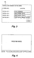
- Key names of the first to fourth control keys 41f to 41i are displayed on the left side of the control code assignment setting screen 100 as shown in FIG. 3 (in FIG. 3 , the key names of the first to fourth control keys 41 f to 41i are displayed as control key 1, control key 2, control key 3, and control key 4, respectively).
- Function boxes used for setting the control codes to be assigned to the first to fourth control keys 41 f to 41 i are displayed correspondingly on the right side of the corresponding key names of the first to fourth control keys 41 f to 41 i on the control code assignment setting screen 100. The function boxes starts out blank or displays the default control codes.
- the television receiver has a CEC (Consumer Electronic Control) function.
- the various control codes (CEC messages) used for CEC control are stored internally ahead of time. Specifically, the control codes are stored in a specific area of the memory component 29. Therefore, when the user presses the directional keys 41 v of the remote control 41 to move the cursor to one of the function boxes, a list of the control codes is displayed next to the function box. Then, the user can select one of the control codes, and assign the control codes to the first to fourth control keys 41 f to 41i, respectively.
- the user sequentially sets the control codes to the first to fourth control keys 41f to 41 i. Once the control codes have been set for all (or some) of the first to fourth control keys 41f to 41i, the cursor is finally moved to an "enter" box displayed in the lower right corner of the control code assignment setting screen 100. Then, if the user presses the enter key 41 w on the remote control 41, the assignment of the control codes for the DVD recorder 30 to the first to fourth control keys 41f to 41i is completed.
- the assignment component 21a of the TV microprocessor 21 generates the control key assignment information based on the assignment set by the user via the control code assignment setting screen 100, and stores the control key assignment information indicating corresponding relationship between the control codes and the first to fourth control keys 41 f to 41i in a specific area of the memory component 29.
- the DVD recorder 30 electrically connected via the HDMI cable 40 can be controlled according to the one of the first to fourth control keys 41 f to 41 i.
- the control component 21 b of the TV microprocessor 21 receives the operation signal indicating that the one of the first to fourth control keys 41 f to 41i is pressed. Then, the control component 21b of the TV microprocessor 21 reads the corresponding control code from the control key assignment information stored in the memory component 29. Then, the control code is transmitted through the HDMI cable 40 to the DVD recorder 30 based on the HDMI standards. Upon receiving the control code, the DVD recorder 30 executes a control operation according to the control code.
- FIG. 3 shows the case in which the first control key 41f (control key 1) is set to “play,” the second control key 41 g (control key 2) is set to “stop,” the third control key 41h (control key 3) is set to “eject,” and the fourth control key 41i (control key 4) is set to "power (on/oft)."
- the user while watching a program on the television receiver, the user decides to play an optical disk (DVD) loaded in the DVD recorder 30. Then, the user presses a mode switching key (not shown) on the remote control 41 to switch the television receiver to video mode (external input mode), and presses the fourth control key 41 i on the remote control 41 to turn on the power to the DVD recorder 30. Furthermore, the user presses the first control key 41f on the remote control 41 to play the optical disk. As a result, the DVD recorder 30 begins reproducing information recorded on the optical disk (or a built-in hard disk, in the case when the DVD recorder 30 includes a built-in hard disk).
- a mode switching key not shown
- control codes have been set as desired by the user to the first to fourth control keys 41 f to 41 i, it is conceivable that the user may forget which of the control codes is set to which of the first to fourth control keys 41 f to 41i. Also, when the television receiver is used at home, if the assignment of the control codes is made by the father, the mother and children may not know which of the control codes is set to which of the first to fourth control keys 41 f to 41 i. Furthermore, the settings made by the father can be further modified by the mother. Therefore, the wrong control keys can be pressed.
- the function display key 41j is disposed on the remote control 41 to display the control key assignment information about the assignment of the control codes to the first to fourth control keys 41f to 41 i.
- the function display key 41j is pressed first to display the control key assignment information before one of the first to fourth control keys 41f to 41i is pressed.
- the control component 21b of the TV microprocessor 21 receives the operation signal indicating that the function display key 41j is operated from the remote control 41, the control component 21 b of the TV microprocessor 21 operates the OSD circuit 24a to display the control key assignment information that indicates the corresponding relationship between the control codes and the first to fourth control keys 41f to 41i stored in the memory component 29.
- control key assignment information is displayed at the bottom part of a program screen that displays a program image received via the tuner circuit 22 or from the DVD recorder 30, as shown in FIG. 4 .
- the user can select one of the first to fourth control keys 41 f to 41 i of the remote control 41 while looking at the corresponding relationship.
- the user is prevented from accidentally pressing the wrong control key.
- the user can freely set the control codes for the DVD recorder 30 and assign the control codes to the first to fourth control keys 41 f to 41 i on the remote control 41.
- This allows the functions that the user wishes to use to be assigned to the first to fourth control keys 41 f to 41 i, respectively.
- the remote control 41 is easier (that is, more convenient) for the user to operate.
- the user can assign the control codes to the first to fourth control keys 41 f to 41 i while viewing the control code assignment setting screen 100.
- the assignment is more easily accomplished, and mistaken assignments can also be prevented.
- the present invention is not limited to the remote control of the television receiver.
- the present invention it is also possible to apply the present invention to DVD recorders, DVD recorders with built-in hard disks, and other such information recording and reproduction devices.
- the remote control 41 of the television receiver it is also possible to apply the remote control 41 of the television receiver to the remote controls used for the information recording and reproduction devices.
- FIG. 5-7 a television receiver in accordance with a second embodiment will now be explained.
- the parts of the second embodiment that are identical to the parts of the first embodiment will be given the same reference numerals as the parts of the first embodiment.
- the descriptions of the parts of the second embodiment that are identical to the parts of the first embodiment may be omitted for the sake of brevity.
- the first to fourth control keys 41 f to 41 i are provided separately on the remote control 41.
- a plurality of number keys 41c of the remote control 41 serves as the control keys.
- the keys can be larger in size, or the space between the keys can be widened.
- the hardware configuration of the television receiver in accordance with the second embodiment is the same as the hardware configuration shown in FIG. 1 .
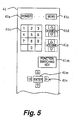
- FIG. 5 is a plan view of the remote control 41.
- the remote control 41 has a power key 41a, a menu key 41b, a plurality of number keys (e.g., control keys) 41c (a number key 41c0 having number "0" to a number key 41c9 having number “9"), channel up and down keys 41 d, volume up and down keys 41e, directional keys 41 v, an enter key 41 w, a function switching key 41m, and so forth.
- the number keys 41c0 to 41c9 is used for numerical input, such as an input of numbers of the channel, for example.
- the number keys 41c0 to 41c9 also serve as control keys for controlling a DVD recorder 30 externally connected to the television receiver.
- the enter key 41 w is disposed in the middle of the directional keys 41 v.
- the function switching key 41 m switches the functions of number keys 41c0 to 41c9 so that the number keys 41c0 to 41c9 serve as the control keys to control the DVD recorder 30. Specifically, the function switching key 41m switches the functions of number keys 41c0 to 41c9 between entering numbers for the television receiver and entering the control codes for the DVD recorder 30. Although not depicted, various other function keys needed for operation are also disposed. The user can freely set the control codes for the DVD recorder 30 to the number keys 41 c0 to 41c9. Here, the number keys 41c0 to 41c9 are differentiated from each other by adding numerals to the number keys 41c.
- the power of the television receiver is turned on. If the user operates the menu key 41b on the remote control 41, then a control component 2 1 b of a TV microprocessor 21 receives an operation signal from the remote control 41 via a receiver 25. Then, a TV signal processor 24 receives a command from the control component 21b of the TV microprocessor 21 to display a menu screen and an OSD circuit 24a displays the menu screen on the monitor 26. The user selects a control key setting category from among the displayed lists of the menu by moving a cursor on the menu screen of the monitor 26 to the control key setting category with the directional keys 41 v, and pressing the enter key 41 w.
- control component 21 b of the TV microprocessor 21 read a control code assignment setting screen 200 for assigning the control codes to the number keys 41c0 to 41c9 shown in FIG. 6 from the memory component 29, and the OSD circuit 24a displays the control code assignment setting screen 200 on the monitor 26.
- Key names of the number keys 41 c0 to 41 c9 are displayed on the left side of the control code assignment setting screen 200 as shown in FIG. 6 .
- Function boxes used for setting the control codes to be assigned to the number keys 41 c0 to 41 c9 are displayed correspondingly on the right side of the corresponding key names of the number keys 41 c0 to 41 c9 on the control code assignment setting screen 200.
- the function boxes starts out blank or displays the default control codes.
- the control codes are stored in a specific area of the memory component 29. Therefore, when the user presses the directional keys 41 v of the remote control 41 to move the cursor to one of the function boxes, a list of the control codes (CEC messages) is displayed next to the function box. Then, the user can select one of the control codes, and assign the control codes to the number keys 41 c0 to 41c9.
- the user sequentially sets the control codes to the number keys 41c0 to 41 c9. Once the control codes have been set for all (or some) of the number keys 41c0 to 41 c9, the cursor is finally moved to an "enter" box displayed in the lower right corner of the control code assignment setting screen 200. Then, if the user presses the enter key 41w on the remote control 41, the assignment of the control codes for the DVD recorder 30 to the number keys 41c0 to 41c9 is completed.
- an assignment component 21a of the TV microprocessor 21 generates the control key assignment information set by the user via the control code assignment setting screen 200, and stores the control key assignment information indicating corresponding relationship between the control codes and the number keys 41c0 to 41c9 in a specific area of the memory component 29.
- the function switching key 41m is pressed to switch the function of the number keys 41 c0 to 41 c9 to the function of the control keys for the DVD recorder 30
- one of the number keys 41c0 to 41 c9 is pressed while the remote control 41 is aimed at the television receiver.
- the DVD recorder 30 externally connected via the HDMI cable 40 can be controlled according to the one of the number keys 41c0 to 41c9.
- the control component 21 b of the TV microprocessor 21 receives the operation signal indicating that the one of the number keys 41c0 to 41 c9 is pressed. Then, the control component 21b of the TV microprocessor 21 reads the corresponding control code from the control key assignment information stored in the memory component 29. Then, the control code (CEC message) is sent through the HDMI cable 40 to the DVD recorder 30. Upon receiving the control code, the DVD recorder 30 executes a control operation according to the control code.
- FIG. 6 shows the case in which the number key 41 c1 (number 1) is set to “play,” the number key 41 c2 (number 2) is set to “stop,” the number key 41c3 (number 3) is set to “eject,” and the number key 41c4 (number 4) is set to "power (on/off)."
- the user while watching a program on the television receiver, the user decides to play an optical disk (DVD) loaded in the DVD recorder 30. Then, the user presses a mode switching key (not shown) on the remote control 41 to switch the television receiver to video mode (external input mode), and presses the function switching key 41m on the remote control 41 to switch the function of the number keys 41c0 to 41c9 to the function of the control keys for the DVD recorder 30. After this, the number key 41 c4 on the remote control 41 is pressed to turn on the power to the DVD recorder 30. Furthermore, the user presses the number key 41c1 on the remote control 41 to play the optical disk. As a result, the DVD recorder 30 begins reproducing information recorded on the optical disk (or a built-in hard disk, in the case when the DVD recorder 30 includes a built-in hard disk).
- control codes have been set as desired by the user to the number keys 41c0 to 41 c9, it is conceivable that the user may forget which of the control codes is set to which of the number keys 41c0 to 41c9. Also, when the television receiver is used at home, if the assignment of the control codes is made by the father, the mother and children may not know which of the control codes is set to which of the number keys 41c0 to 41 c9. Furthermore, the settings made by the father can be further modified by the mother. Therefore, the wrong number keys 41c0 to 41 c9 can be pressed.
- the function switching key 41m is disposed on the remote control 41 to display the control key assignment information about the assignment of the control codes to the number keys 41 c0 to 41 c9.
- the control component 21b of the TV microprocessor 21 receives the operation signal indicating that the function display key 41j is operated from the remote control 41. Then, the control component 21b of the TV microprocessor 21 operates the OSD circuit 24a to display the control key assignment information that is the corresponding relationship between the control codes and the number keys 41c0 to 41c9 stored in the memory component 29.
- control key assignment information is displayed at the bottom part of a program screen that displays a program image received via the tuner circuit 22 or from the DVD recorder 30, as shown in FIG. 7 .
- the user can operate the number keys 41 c0 to 41c9 of the remote control 41 as the control keys while looking at the corresponding relationship.
- the user is prevented from accidentally pressing the wrong control key.
- the number keys and the corresponding control functions are merely displayed in text form.
- the same key layout as that of the number keys 41c0 to 41c9 on the remote control 41 can be displayed in the corner of the program screen, and the words “play,” “stop,” “eject,” and “power” can be written under or in the middle of the corresponding number keys 41 c0 to 41 c9.
- This allows the user to confirm the various control functions with the same layout as that of the number keys 41c0 to 41 c9 on the actual remote control 41. As a result, the accidental pressing of the wrong number keys 41c0 to 41 c9 is prevented even more effectively.
- the number keys 41c0 to 41 c9 to be pressed can be selected while visually confirming the control key assignment information on the screen.
- the user can easily and quickly determine which number keys 41c0 to 41c9 are to be pressed, and press the number keys 41 c0 to 41c0. This makes the remote control easier to operate for the user.
- the number keys 41c0 to 41c9 also serve as the control keys, the number of keys that have to be arranged on the remote control 41 can be reduced. This means the individual keys do not have to be made as small as in the past, or laid out as closely together. Thus, operational functions can be diversified while the ease of remote control operation can be kept the same.
Abstract
Description
- This application claims priority to Japanese Patent Application No.
2007-229110 filed on September 4, 2007 2007-229110 - The present invention generally relates to an electronic device. More specifically, the present invention relates to an electronic device that is connected to an external electronic device via a control cable.
- As advances have been made in recent years in liquid crystal panel manufacturing technology, we have seen greater resolution in display of television receivers. The television receivers are used with DVD recorders, DVD recorders with built-in hard disks, and other such information recording and reproduction devices. Between the television receivers and the information recording and reproduction devices, large quantities of video and audio data are sent and received. Thus, an HDMI (High Definition Multimedia Interface) interface circuit has been used to connect between the television receivers and the information recording and reproduction devices.
- The HDMI is an interface for transmitting various kinds of data, including video and audio data, between a sending side, such as a television receiver or a projector, and a receiving side, such as a DVD recorder or a DVD recorder with a built-in hard disk. A CEC (Consumer Electronics Control) function of the HDMI allows power of the information recording and reproduction device to be switched on when power of the television receiver is switched on, for example.
- Recently, there have been proposed a variety of electronic devices that have an HDMI terminal that meets the HDMI standards. The electronic devices can be connected via an HDMI cable to another electronic device that meets the HDMI standards.
- With a conventional AV system discussed in Japanese Laid-Open Patent Application Publication No.
2007-97095 - When the user operates a switch in the other device switch group of the remote control, a control code assigned to a function corresponding to the switch is transmitted as a remote control signal. Then, the remote control signal is received by a remote control receiver of the television set made by company A. Furthermore, when a CPU of the television set made by company A recognizes the control code received through the remote control receiver as a control code for controlling the DVD player made by the company B, the received control code is converted into a corresponding common control code based on a conversion table. Then, the converted common control code is transmitted through an AV cable to the DVD player made by company B. A CPU of the DVD player made by company B converts the common control code received from the television set made by company A into a company B-specific code based on a conversion table. As a result, the DVD player is operated based on the converted company B-specific code.
- With the conventional AV system, control codes for other devices (the ones to be controlled) are pre-assigned to the switches of the other device switch group provided to the remote control. Therefore, the user has to remember which control code is assigned to which switch. Also, users use remote controls in different ways. Thus, some switches used often and others less often. However, when the control codes are pre-assigned to each of the switches of the other device switch group, depending on the user, the control codes that are not used very often are assigned to switches in easy-to-operate locations, and the control codes that are used frequently are assigned to switches in difficult-to-operate locations.
- Also, with the conventional AV system, since the other device switch group is provided separately from the dedicated switch group, there are more switches on the remote control. However, since the remote control itself is required to be smaller, the size of the switches themselves ends up being smaller, or the switches have to be positioned more closely together. As a result, it becomes more difficult for the user to operate the remote control.
- In view of the above, it will be apparent to those skilled in the art from this disclosure that there exists a need for an improved electric device. This invention addresses this need in the art as well as other needs, which will become apparent to those skilled in the art from this disclosure.
- The present invention is conceived in light of the above-mentioned problems. One object of the present invention is to provide an electric device that makes it easier to operate an external electronic device connected to the electric device with a remote control of the electric device.
- In accordance with one aspect of the present invention, an electronic device is electrically connected to an external electronic device. The electronic device includes an assignment component, a memory component and a control component. The assignment component is configured to assign control codes that control operations of the external electronic device to a plurality of control keys of a remote control to generate assignment information indicating corresponding relationship between the control codes and the control keys of the remote control. The memory component is configured to store the assignment information generated by the assignment component. The control component is configured to control the external electronic device based on the assignment information stored in the memory component when the control component receives an operation signal indicating that one of the control keys of the remote control is operated.
- With the electric device of the present invention, it is possible to provide an electric device that makes it easier to operate an external electronic device connected to the electric device with a remote control of the electric device.
- These and other objects, features, aspects and advantages of the present invention will become apparent to those skilled in the art from the following detailed descriptions, which, taken in conjunction with the annexed drawings, disclose selected embodiments of the present invention.
- Referring now to the attached drawings which form a part of this original disclosure:
-
FIG. 1 is a block diagram illustrating a television receiver in accordance with a first embodiment of the present invention; -
FIG. 2 is a plan view of a remote control of the television receiver illustrated inFIG. 1 ; -
FIG. 3 is a screen shot of a control code assignment setting screen; -
FIG. 4 is a screen shot of a control key assignment information displayed on a program screen; -
FIG. 5 is a plan view of a remote control of a television receiver in accordance with a second embodiment of the present invention; -
FIG. 6 is a screen shot of a control code assignment setting screen; and -
FIG. 7 is a screen shot of a control key assignment information displayed on a program screen. - Selected embodiments of the present invention will now be explained with reference to the drawings. It will be apparent to those skilled in the art from these disclosures that the following descriptions of the selected embodiments of the present invention are provided for illustration only and not for the purpose of limiting the invention as defined by the appended claims and their equivalents.
-
FIG. 1 is a block diagram of a television receiver (e.g., electronic device). The television receiver receives digital broadcasts. The television receiver includes aTV control system 20 housed in a casing of the television receiver. TheTV control system 20 further includes aTV microprocessor 21, atuner circuit 22, TV signal processor (e.g., television receiving component) 24, areceiver 25, amonitor 26, anamplifier 27, ainternal speaker 28 and amemory component 29. TheTV microprocessor 21 controls the entireTV control system 20. TheTV microprocessor 21 includes anassignment component 21 a and acontrol component 21b. Theassignment component 21 a assigns control codes to first tofourth control keys 41 f to 41i of a remote control transmitter (hereinafter referred to as "remote control") 41 shown inFIG. 2 , and generates control key assignment information. The control codes are operation commands that control operations of a DVD recorder (e.g., external electronic device) 30 externally connected to the television receiver. The control key assignment information indicates corresponding relationship between the control codes and the first tofourth control keys 41f to 41i of theremote control 41. Thecontrol component 21 b controls theDVD recorder 30 based on the control key assignment information. Thetuner circuit 22 receives digital television signals of the digital broadcasts. An output of thetuner circuit 22 is connected to theTV signal processor 24. TheTV signal processor 24 performs signal processing of the digital broadcasts. Specifically, theTV signal processor 24 performs video and audio signal processing of the digital broadcasts. An output of theTV signal processor 24 is connected to themonitor 26. The monitor includes a display device, such as a CRT, a liquid crystal panel, and the like. The output of theTV signal processor 24 is also connected to theinternal speaker 28 via theamplifier 27. - The
TV signal processor 24 has an OSD circuit (e.g., display component) 24a and an HDMI (High Definition Multimedia Interface) terminal 24b. TheOSD circuit 24a displays various setting screens on themonitor 26. Specifically, theOSD circuit 24a displays a menu screen for performing various settings of the television receiver, a channel tuning screen when a channel is changed, or a control key assignment setting screen (e.g., assignment setting screen) 100. TheHDMI terminal 24b is an input/output terminal for digital signals (digital video signal, digital audio signal or digital control signal) that meets HDMI standards. TheHDMI terminal 24b is connected via anHDMI cable 40 to anHDMI terminal 30a of theDVD recorder 30 that meets HDMI standards. TheHDMI terminal 24b transmits the control codes to theDVD recorder 30. TheDVD recorder 30 is electrically and externally connected to the television receiver. - The
TV signal processor 24 decodes the digital television signals received via thetuner circuit 22 into the digital video and audio signals. TheTV signal processor 24 also displays the video signal on themonitor 26 and outputs the audio signal from theinternal speaker 28. Thecontrol component 21 b of theTV microprocessor 21 controls theTV signal processor 24. - The
receiver 25 receives various operation signals from theremote control 41 of the television receiver. TheTV microprocessor 21 is connected to an output of thereceiver 25. Thecontrol component 21b of theTV microprocessor 21 performs operational control of theTV control system 20, setting of the control codes of theDVD recorder 30 and control processing of theDVD recorder 30 based on the various operation signals sent from theremote control 41. - The
memory component 29 is connected to theTV microprocessor 21. Thememory component 29 stores a channel table, processing programs, the control codes, the control key assignment information, etc. The channel table is a table information in which various channels have been set by auto-preset or the like through operation of theremote control 41. The processing programs is programs for setting connection settings (such as video and audio settings) when the television receiver is connected via theHDMI cable 40 to theDVD recorder 30. The control codes are operation command for theDVD recorder 30. Specifically, the control codes include CEC (Consumer Electric Control) messages defined by the HDMI standards. The control key assignment information is set by the user by operating theremote control 41. The control key assignment information is set sequentially from the control codeassignment setting screen 100 shown inFIG. 3 by operating theremote control 41. The control keyassignment setting screen 100 prompts to input an assignment of the control codes to the control keys. -
FIG. 2 is a plan view of theremote control 41. - The
remote control 41 has apower key 41a, a menu key 41 b,number keys 41 c, channel up and downkeys 41 d, volume up and downkeys 41e, a plurality of first to fourth control keys (e.g., control keys) 41 f to 41 i, a function display key (e.g., assignment information display key) 41j,directional keys 41 v, anenter key 41w, and so forth. Although not depicted, various other function keys needed for operation can be also disposed. The first tofourth control keys 41 f to 41i is keys for controlling the DVD recorder 30 (four in this example, but the number is not limited to four). The function display key 41j is a key for displaying the control key assignment information set to the first tofourth control keys 41 f to 41 i on themonitor 26. Theenter key 41 w is disposed in the middle of thedirectional keys 41v. The user can freely set (assign) the control codes for theDVD recorder 30 to the first tofourth control keys 41f to 41i. However, even if the user has not set any control codes, default control codes are preset to the first tofourth control keys 41f to 41 i. Therefore, the user can use the first tofourth control keys 41 f to 41i with default functions corresponding to the default control codes without assigning the control codes to the first tofourth control keys 41 f to 41i. - The processing in which the user sets (assigns) the control codes to the first to
fourth control keys 41 f to 41i will now be described in detail. - First, the power of the television receiver is turned on. If the user operates the menu key 41 b on the
remote control 41, then thecontrol component 21 b of theTV microprocessor 21 receives an operation signal from theremote control 41 via thereceiver 25. Then, theTV signal processor 24 receives a command from thecontrol component 21b of theTV microprocessor 21 to display a menu screen and theOSD circuit 24a displays the menu screen on themonitor 26. The user selects a control key setting category from among displayed lists of the menu by moving a cursor on the menu screen of themonitor 26 to the control key setting category with thedirectional keys 41v, and pressing theenter key 41 w. As a result, thecontrol component 21 b of theTV microprocessor 21 read the control codeassignment setting screen 100 for assigning the control codes (functions) to the first tofourth control keys 41 f to 41 i from thememory component 29, and theOSD circuit 24a displays the control codeassignment setting screen 100 on themonitor 26. The cursor referred to here includes not only a graphic display such as a pointer, but also a display in which the category is inverted or highlighted, for example, so as to make the display form stand out. - Key names of the first to
fourth control keys 41f to 41i are displayed on the left side of the control codeassignment setting screen 100 as shown inFIG. 3 (inFIG. 3 , the key names of the first tofourth control keys 41 f to 41i are displayed ascontrol key 1,control key 2,control key 3, andcontrol key 4, respectively). Function boxes used for setting the control codes to be assigned to the first tofourth control keys 41 f to 41 i are displayed correspondingly on the right side of the corresponding key names of the first tofourth control keys 41 f to 41 i on the control codeassignment setting screen 100. The function boxes starts out blank or displays the default control codes. - The television receiver has a CEC (Consumer Electronic Control) function. The various control codes (CEC messages) used for CEC control are stored internally ahead of time. Specifically, the control codes are stored in a specific area of the
memory component 29. Therefore, when the user presses thedirectional keys 41 v of theremote control 41 to move the cursor to one of the function boxes, a list of the control codes is displayed next to the function box. Then, the user can select one of the control codes, and assign the control codes to the first tofourth control keys 41 f to 41i, respectively. - The user sequentially sets the control codes to the first to
fourth control keys 41f to 41 i. Once the control codes have been set for all (or some) of the first tofourth control keys 41f to 41i, the cursor is finally moved to an "enter" box displayed in the lower right corner of the control codeassignment setting screen 100. Then, if the user presses theenter key 41 w on theremote control 41, the assignment of the control codes for theDVD recorder 30 to the first tofourth control keys 41f to 41i is completed. Specifically, theassignment component 21a of theTV microprocessor 21 generates the control key assignment information based on the assignment set by the user via the control codeassignment setting screen 100, and stores the control key assignment information indicating corresponding relationship between the control codes and the first tofourth control keys 41 f to 41i in a specific area of thememory component 29. As a result, when one of the first tofourth control keys 41f to 41 i is pressed while theremote control 41 is aimed at the television receiver, theDVD recorder 30 electrically connected via theHDMI cable 40 can be controlled according to the one of the first tofourth control keys 41 f to 41 i. Specifically, when one of the first tofourth control keys 41 f to 41i is pressed, thecontrol component 21 b of theTV microprocessor 21 receives the operation signal indicating that the one of the first tofourth control keys 41 f to 41i is pressed. Then, thecontrol component 21b of theTV microprocessor 21 reads the corresponding control code from the control key assignment information stored in thememory component 29. Then, the control code is transmitted through theHDMI cable 40 to theDVD recorder 30 based on the HDMI standards. Upon receiving the control code, theDVD recorder 30 executes a control operation according to the control code. -
FIG. 3 shows the case in which thefirst control key 41f (control key 1) is set to "play," the second control key 41 g (control key 2) is set to "stop," thethird control key 41h (control key 3) is set to "eject," and the fourth control key 41i (control key 4) is set to "power (on/oft)." - For example, while watching a program on the television receiver, the user decides to play an optical disk (DVD) loaded in the
DVD recorder 30. Then, the user presses a mode switching key (not shown) on theremote control 41 to switch the television receiver to video mode (external input mode), and presses the fourth control key 41 i on theremote control 41 to turn on the power to theDVD recorder 30. Furthermore, the user presses the first control key 41f on theremote control 41 to play the optical disk. As a result, theDVD recorder 30 begins reproducing information recorded on the optical disk (or a built-in hard disk, in the case when theDVD recorder 30 includes a built-in hard disk). - Since the control codes have been set as desired by the user to the first to
fourth control keys 41 f to 41 i, it is conceivable that the user may forget which of the control codes is set to which of the first tofourth control keys 41 f to 41i. Also, when the television receiver is used at home, if the assignment of the control codes is made by the father, the mother and children may not know which of the control codes is set to which of the first tofourth control keys 41 f to 41 i. Furthermore, the settings made by the father can be further modified by the mother. Therefore, the wrong control keys can be pressed. - In view of this, with the television receiver, the function display key 41j is disposed on the
remote control 41 to display the control key assignment information about the assignment of the control codes to the first tofourth control keys 41f to 41 i. The function display key 41j is pressed first to display the control key assignment information before one of the first tofourth control keys 41f to 41i is pressed. When thecontrol component 21b of theTV microprocessor 21 receives the operation signal indicating that the function display key 41j is operated from theremote control 41, thecontrol component 21 b of theTV microprocessor 21 operates theOSD circuit 24a to display the control key assignment information that indicates the corresponding relationship between the control codes and the first tofourth control keys 41f to 41i stored in thememory component 29. Specifically, the control key assignment information is displayed at the bottom part of a program screen that displays a program image received via thetuner circuit 22 or from theDVD recorder 30, as shown inFIG. 4 . As a result, the user can select one of the first tofourth control keys 41 f to 41 i of theremote control 41 while looking at the corresponding relationship. Thus, the user is prevented from accidentally pressing the wrong control key. - With the television receiver, the user can freely set the control codes for the
DVD recorder 30 and assign the control codes to the first tofourth control keys 41 f to 41 i on theremote control 41. This allows the functions that the user wishes to use to be assigned to the first tofourth control keys 41 f to 41 i, respectively. Thus, theremote control 41 is easier (that is, more convenient) for the user to operate. - With the television receiver, the user can assign the control codes to the first to
fourth control keys 41 f to 41 i while viewing the control codeassignment setting screen 100. Thus, the assignment is more easily accomplished, and mistaken assignments can also be prevented. - The present invention is not limited to the remote control of the television receiver. For instance, it is also possible to apply the present invention to DVD recorders, DVD recorders with built-in hard disks, and other such information recording and reproduction devices. Furthermore, it is also possible to apply the
remote control 41 of the television receiver to the remote controls used for the information recording and reproduction devices. - Referring now to
FIG. 5-7 , a television receiver in accordance with a second embodiment will now be explained. In view of the similarity between the first and second embodiments, the parts of the second embodiment that are identical to the parts of the first embodiment will be given the same reference numerals as the parts of the first embodiment. Moreover, the descriptions of the parts of the second embodiment that are identical to the parts of the first embodiment may be omitted for the sake of brevity. - In the first embodiment, the first to
fourth control keys 41 f to 41 i are provided separately on theremote control 41. In the second embodiment, a plurality ofnumber keys 41c of theremote control 41 serves as the control keys. As a result, there are less keys disposed on theremote control 41. Thus, the keys can be larger in size, or the space between the keys can be widened. The hardware configuration of the television receiver in accordance with the second embodiment is the same as the hardware configuration shown inFIG. 1 . -
FIG. 5 is a plan view of theremote control 41. - The
remote control 41 has apower key 41a, a menu key 41b, a plurality of number keys (e.g., control keys) 41c (a number key 41c0 having number "0" to a number key 41c9 having number "9"), channel up and downkeys 41 d, volume up and downkeys 41e,directional keys 41 v, anenter key 41 w, a function switching key 41m, and so forth. The number keys 41c0 to 41c9 is used for numerical input, such as an input of numbers of the channel, for example. The number keys 41c0 to 41c9 also serve as control keys for controlling aDVD recorder 30 externally connected to the television receiver. Theenter key 41 w is disposed in the middle of thedirectional keys 41 v. The function switching key 41 m switches the functions of number keys 41c0 to 41c9 so that the number keys 41c0 to 41c9 serve as the control keys to control theDVD recorder 30. Specifically, the function switching key 41m switches the functions of number keys 41c0 to 41c9 between entering numbers for the television receiver and entering the control codes for theDVD recorder 30. Although not depicted, various other function keys needed for operation are also disposed. The user can freely set the control codes for theDVD recorder 30 to thenumber keys 41 c0 to 41c9. Here, the number keys 41c0 to 41c9 are differentiated from each other by adding numerals to thenumber keys 41c. - The setting operation in which the user sets (assigns) the control codes to the number keys 41c0 to 41c9 will now be described in detail.
- First, the power of the television receiver is turned on. If the user operates the menu key 41b on the
remote control 41, then acontrol component 2 1 b of aTV microprocessor 21 receives an operation signal from theremote control 41 via areceiver 25. Then, aTV signal processor 24 receives a command from thecontrol component 21b of theTV microprocessor 21 to display a menu screen and anOSD circuit 24a displays the menu screen on themonitor 26. The user selects a control key setting category from among the displayed lists of the menu by moving a cursor on the menu screen of themonitor 26 to the control key setting category with thedirectional keys 41 v, and pressing theenter key 41 w. As a result, thecontrol component 21 b of theTV microprocessor 21 read a control codeassignment setting screen 200 for assigning the control codes to the number keys 41c0 to 41c9 shown inFIG. 6 from thememory component 29, and theOSD circuit 24a displays the control codeassignment setting screen 200 on themonitor 26. - Key names of the
number keys 41 c0 to 41 c9 are displayed on the left side of the control codeassignment setting screen 200 as shown inFIG. 6 . Function boxes used for setting the control codes to be assigned to thenumber keys 41 c0 to 41 c9 are displayed correspondingly on the right side of the corresponding key names of thenumber keys 41 c0 to 41 c9 on the control codeassignment setting screen 200. The function boxes starts out blank or displays the default control codes. - The control codes are stored in a specific area of the
memory component 29. Therefore, when the user presses thedirectional keys 41 v of theremote control 41 to move the cursor to one of the function boxes, a list of the control codes (CEC messages) is displayed next to the function box. Then, the user can select one of the control codes, and assign the control codes to thenumber keys 41 c0 to 41c9. - The user sequentially sets the control codes to the number keys 41c0 to 41 c9. Once the control codes have been set for all (or some) of the number keys 41c0 to 41 c9, the cursor is finally moved to an "enter" box displayed in the lower right corner of the control code
assignment setting screen 200. Then, if the user presses theenter key 41w on theremote control 41, the assignment of the control codes for theDVD recorder 30 to the number keys 41c0 to 41c9 is completed. Specifically, anassignment component 21a of theTV microprocessor 21 generates the control key assignment information set by the user via the control codeassignment setting screen 200, and stores the control key assignment information indicating corresponding relationship between the control codes and the number keys 41c0 to 41c9 in a specific area of thememory component 29. As a result, after the function switching key 41m is pressed to switch the function of thenumber keys 41 c0 to 41 c9 to the function of the control keys for theDVD recorder 30, one of the number keys 41c0 to 41 c9 is pressed while theremote control 41 is aimed at the television receiver. Then, theDVD recorder 30 externally connected via theHDMI cable 40 can be controlled according to the one of the number keys 41c0 to 41c9. Specifically, when one of thenumber keys 41 c0 to 41 c9 is pressed, thecontrol component 21 b of theTV microprocessor 21 receives the operation signal indicating that the one of the number keys 41c0 to 41 c9 is pressed. Then, thecontrol component 21b of theTV microprocessor 21 reads the corresponding control code from the control key assignment information stored in thememory component 29. Then, the control code (CEC message) is sent through theHDMI cable 40 to theDVD recorder 30. Upon receiving the control code, theDVD recorder 30 executes a control operation according to the control code. -
FIG. 6 shows the case in which thenumber key 41 c1 (number 1) is set to "play," thenumber key 41 c2 (number 2) is set to "stop," the number key 41c3 (number 3) is set to "eject," and the number key 41c4 (number 4) is set to "power (on/off)." - For example, while watching a program on the television receiver, the user decides to play an optical disk (DVD) loaded in the
DVD recorder 30. Then, the user presses a mode switching key (not shown) on theremote control 41 to switch the television receiver to video mode (external input mode), and presses the function switching key 41m on theremote control 41 to switch the function of the number keys 41c0 to 41c9 to the function of the control keys for theDVD recorder 30. After this, thenumber key 41 c4 on theremote control 41 is pressed to turn on the power to theDVD recorder 30. Furthermore, the user presses the number key 41c1 on theremote control 41 to play the optical disk. As a result, theDVD recorder 30 begins reproducing information recorded on the optical disk (or a built-in hard disk, in the case when theDVD recorder 30 includes a built-in hard disk). - Since the control codes have been set as desired by the user to the number keys 41c0 to 41 c9, it is conceivable that the user may forget which of the control codes is set to which of the number keys 41c0 to 41c9. Also, when the television receiver is used at home, if the assignment of the control codes is made by the father, the mother and children may not know which of the control codes is set to which of the number keys 41c0 to 41 c9. Furthermore, the settings made by the father can be further modified by the mother. Therefore, the wrong number keys 41c0 to 41 c9 can be pressed.
- In view of this, with the television receiver, the function switching key 41m is disposed on the
remote control 41 to display the control key assignment information about the assignment of the control codes to thenumber keys 41 c0 to 41 c9. When the function switching key 41m is pressed, thecontrol component 21b of theTV microprocessor 21 receives the operation signal indicating that the function display key 41j is operated from theremote control 41. Then, thecontrol component 21b of theTV microprocessor 21 operates theOSD circuit 24a to display the control key assignment information that is the corresponding relationship between the control codes and the number keys 41c0 to 41c9 stored in thememory component 29. Specifically, the control key assignment information is displayed at the bottom part of a program screen that displays a program image received via thetuner circuit 22 or from theDVD recorder 30, as shown inFIG. 7 . As a result, the user can operate thenumber keys 41 c0 to 41c9 of theremote control 41 as the control keys while looking at the corresponding relationship. Thus, the user is prevented from accidentally pressing the wrong control key. InFIG. 7 , the number keys and the corresponding control functions are merely displayed in text form. However, the same key layout as that of the number keys 41c0 to 41c9 on theremote control 41 can be displayed in the corner of the program screen, and the words "play," "stop," "eject," and "power" can be written under or in the middle of thecorresponding number keys 41 c0 to 41 c9. This allows the user to confirm the various control functions with the same layout as that of the number keys 41c0 to 41 c9 on the actualremote control 41. As a result, the accidental pressing of the wrong number keys 41c0 to 41 c9 is prevented even more effectively. - When the function switching key 41m is pressed again in this state, the number keys 41c0 to 41 c9 are restored to the usual key functions for numerical input.
- With the television receiver, since the control key assignment information about the assignment of the control codes is displayed on-screen when the
number keys 41 c0 to 41 c9 are used to control theDVD recorder 30, the number keys 41c0 to 41 c9 to be pressed can be selected while visually confirming the control key assignment information on the screen. Thus, the user can easily and quickly determine which number keys 41c0 to 41c9 are to be pressed, and press thenumber keys 41 c0 to 41c0. This makes the remote control easier to operate for the user. - Also, with the television receiver, because the number keys 41c0 to 41c9 also serve as the control keys, the number of keys that have to be arranged on the
remote control 41 can be reduced. This means the individual keys do not have to be made as small as in the past, or laid out as closely together. Thus, operational functions can be diversified while the ease of remote control operation can be kept the same. - In understanding the scope of the present invention, the term "comprising" and its derivatives, as used herein, are intended to be open ended terms that specify the presence of the stated features, elements, components and groups, but do not exclude the presence of other unstated features, elements, components and groups. The foregoing also applies to words having similar meanings such as the terms, "including", "having" and their derivatives. Also, the terms "part," "section," "portion," "member" or "element" when used in the singular can have the dual meaning of a single part or a plurality of parts. As used herein to describe the present invention, the following directional terms "forward, rearward, above, downward, vertical, horizontal, below and transverse" as well as any other similar directional terms refer to those directions of an electric device equipped with the present invention. Accordingly, these terms, as utilized to describe the present invention should be interpreted relative to an electric device equipped with the present invention as used in the normal operating position.
- While selected embodiments have been chosen to illustrate the present invention, it will be apparent to those skilled in the art from these disclosures that various changes and modifications can be made herein without departing from the scope of the invention as defined in the appended claims. Furthermore, the foregoing descriptions of the selected embodiments according to the present invention are provided for illustration only, and not for the purpose of limiting the invention as defined by the appended claims and their equivalents.
Claims (15)
- An electronic device electrically connected to an external electronic device, comprising:an assignment component configured to assign control codes that control operations of the external electronic device to a plurality of control keys of a remote control to generate assignment information indicating corresponding relationship between the control codes and the control keys of the remote control;a memory component configured to store the assignment information generated by the assignment component; anda control component configured to control the external electronic device based on the assignment information stored in the memory component when the control component receives an operation signal indicating that one of the control keys of the remote control is operated.
- The electronic device according to claim 1, further comprising
a display component configured to display an assignment setting screen that prompt to input an assignment of the control codes to the control keys,
the assignment component being further configured to assign the control codes to the control keys based on the assignment of the control codes to the control keys inputted via the assignment setting screen. - The electronic device according to claim 1, further comprising
a display component operatively coupled to the control component, and configured to display the assignment information stored in the memory component when the control component receives an operation signal indicating that an assignment information display key of the remote control is operated. - The electronic device according to claim 1, wherein
the remote control further has a function switching key being configured to switch a function of a plurality of number keys of the remote control for numerical input so that the number keys serve as the control keys to control the external electronic device. - The electronic device according to claim 4, further comprising
a display component operatively coupled to the control component, and configured to display the assignment information that is stored in the memory component and indicates the corresponding relationship between the control codes and the number keys when the control component receives an operation signal indicating that the function switching key of the remote control is operated. - The electronic device according to claim 1, wherein
the control component is further configured to control the external electronic device by transmitting the control codes to the external electronic device based on HDMI (High Definition Multimedia Interface) standards. - The electronic device according to claim 6, further comprising
an HDMI terminal electrically connected to an HDMI terminal of the external electronic device, and configured to transmit the control codes to the external electronic device. - The electronic device according to claim 6, wherein
the control component is further configured to transmit the control codes including a CEC (Consumer Electronics Control) message defined by the HDMI standards. - The electronic device according to claim 1, further comprising
a television receiving component configured to be controlled by the remote control to receive television broadcasts. - The electronic device according to claim 2, wherein
the control component is further configured to control the external electronic device by transmitting the control codes to the external electronic device based on HDMI (High Definition Multimedia Interface) standards. - The electronic device according to claim 2, further comprising
a television receiving component configured to be controlled by the remote control to receive television broadcasts. - The electronic device according to claim 3, wherein
the control component is further configured to control the external electronic device by transmitting the control codes to the external electronic device based on HDMI (High Definition Multimedia Interface) standards. - The electronic device according to claim 3, further comprising
a television receiving component configured to be controlled by the remote control to receive television broadcasts. - The electronic device according to claim 4, wherein
the control component is further configured to control the external electronic device by transmitting the control codes to the external electronic device based on HDMI (High Definition Multimedia Interface) standards. - The electronic device according to claim 4, further comprising
a television receiving component configured to be controlled by the remote control to receive television broadcasts.
Applications Claiming Priority (1)
| Application Number | Priority Date | Filing Date | Title |
|---|---|---|---|
| JP2007229110A JP2009065267A (en) | 2007-09-04 | 2007-09-04 | Electronic equipment |
Publications (2)
| Publication Number | Publication Date |
|---|---|
| EP2034465A2 true EP2034465A2 (en) | 2009-03-11 |
| EP2034465A3 EP2034465A3 (en) | 2013-01-23 |
Family
ID=40149611
Family Applications (1)
| Application Number | Title | Priority Date | Filing Date |
|---|---|---|---|
| EP08015491A Withdrawn EP2034465A3 (en) | 2007-09-04 | 2008-09-02 | Electronic device |
Country Status (3)
| Country | Link |
|---|---|
| US (1) | US8237862B2 (en) |
| EP (1) | EP2034465A3 (en) |
| JP (1) | JP2009065267A (en) |
Families Citing this family (2)
| Publication number | Priority date | Publication date | Assignee | Title |
|---|---|---|---|---|
| JP4839491B2 (en) * | 2009-06-02 | 2011-12-21 | Necアクセステクニカ株式会社 | Information transmission system |
| US8922615B2 (en) * | 2011-12-16 | 2014-12-30 | Logitech Europe S.A. | Customizing input to a videoconference using a remote control device |
Citations (2)
| Publication number | Priority date | Publication date | Assignee | Title |
|---|---|---|---|---|
| JP2007097095A (en) | 2005-09-30 | 2007-04-12 | Matsushita Electric Ind Co Ltd | Av system and control method thereof |
| JP2007229110A (en) | 2006-02-28 | 2007-09-13 | Morita Mfg Co Ltd | Dental root canal treatment device |
Family Cites Families (23)
| Publication number | Priority date | Publication date | Assignee | Title |
|---|---|---|---|---|
| DE3827050A1 (en) * | 1988-08-10 | 1990-02-15 | Thomson Brandt Gmbh | TELEVISION RECEIVER |
| US5410326A (en) * | 1992-12-04 | 1995-04-25 | Goldstein; Steven W. | Programmable remote control device for interacting with a plurality of remotely controlled devices |
| JP3612696B2 (en) * | 1996-12-18 | 2005-01-19 | ソニー株式会社 | Information processing apparatus and method, and remote control system |
| WO2000070578A1 (en) * | 1999-05-12 | 2000-11-23 | Koninklijke Philips Electronics N.V. | System and method for controlling multiple home electronics devices |
| GB0208317D0 (en) * | 2002-04-11 | 2002-05-22 | Koninkl Philips Electronics Nv | Controlling a home electronics system |
| US7170422B2 (en) * | 2002-06-24 | 2007-01-30 | Matsushita Electric Industrial Co., Ltd. | Personal programmable universal remote control |
| US7109908B2 (en) * | 2002-10-18 | 2006-09-19 | Contec Corporation | Programmable universal remote control unit |
| JP4369214B2 (en) * | 2002-12-11 | 2009-11-18 | パナソニック株式会社 | AV system |
| US20040174288A1 (en) * | 2003-03-05 | 2004-09-09 | Park Chang K. | Programmable universal control |
| US7330174B2 (en) * | 2003-03-27 | 2008-02-12 | General Instrument Corporation | Method and apparatus for a programmable electrophoretic remote control |
| US7046185B2 (en) * | 2003-06-19 | 2006-05-16 | Contec Corporation | Programmable universal remote control unit and method of programming same |
| US20050120383A1 (en) * | 2003-12-02 | 2005-06-02 | Ozaki Arthur H. | System for saving settings of an audiovisual system |
| JP2005198115A (en) * | 2004-01-08 | 2005-07-21 | Toshiba Corp | Remote controller |
| JP4225418B2 (en) * | 2004-02-05 | 2009-02-18 | ソニー株式会社 | Compound equipment |
| US20060087445A1 (en) * | 2004-10-25 | 2006-04-27 | Green Stuart A | Programmable remote controller adapted to be programmed by playback of audiovisual content |
| US7692635B2 (en) * | 2005-02-28 | 2010-04-06 | Sony Corporation | User interface with thin display device |
| KR100781509B1 (en) * | 2005-04-27 | 2007-12-03 | 삼성전자주식회사 | Display apparatus and method for offering functions of integrated remote control |
| JP2009517949A (en) * | 2005-11-30 | 2009-04-30 | コーニンクレッカ フィリップス エレクトロニクス エヌ ヴィ | General-purpose remote control device settings |
| US20080001773A1 (en) * | 2006-06-29 | 2008-01-03 | X10 Ltd. | Programmable remote control and methods of using same |
| US7952467B2 (en) * | 2006-09-29 | 2011-05-31 | Sony Corporation | System and method for informing user how to use universal remote control |
| US7719438B2 (en) * | 2006-10-10 | 2010-05-18 | Sony Corporation | System and method for universal remote control |
| US7224410B1 (en) * | 2006-10-19 | 2007-05-29 | Gerstman George H | Remote control device for a television receiver with user programmable means |
| US20080174467A1 (en) * | 2007-01-23 | 2008-07-24 | Laszlo Drimusz | Universal remote control programming |
-
2007
- 2007-09-04 JP JP2007229110A patent/JP2009065267A/en active Pending
-
2008
- 2008-08-28 US US12/199,872 patent/US8237862B2/en not_active Expired - Fee Related
- 2008-09-02 EP EP08015491A patent/EP2034465A3/en not_active Withdrawn
Patent Citations (2)
| Publication number | Priority date | Publication date | Assignee | Title |
|---|---|---|---|---|
| JP2007097095A (en) | 2005-09-30 | 2007-04-12 | Matsushita Electric Ind Co Ltd | Av system and control method thereof |
| JP2007229110A (en) | 2006-02-28 | 2007-09-13 | Morita Mfg Co Ltd | Dental root canal treatment device |
Also Published As
| Publication number | Publication date |
|---|---|
| JP2009065267A (en) | 2009-03-26 |
| US8237862B2 (en) | 2012-08-07 |
| US20090059092A1 (en) | 2009-03-05 |
| EP2034465A3 (en) | 2013-01-23 |
Similar Documents
| Publication | Publication Date | Title |
|---|---|---|
| EP1641134A2 (en) | Integrated remote control device and method for controlling multiple devices | |
| US7949230B2 (en) | Electronic equipment, system for video content, and display method | |
| US9319616B2 (en) | Control method of an audio/video system | |
| US8306402B2 (en) | Time shift view/listening system, display device, and time shift view/listening method | |
| US20040066308A1 (en) | Systems and methods for implementing a learning remote control | |
| EP2048882A1 (en) | Display apparatus | |
| EP1998562A2 (en) | Digital video apparatus and method for controlling digital video apparatus | |
| US8212707B2 (en) | Remote control system and remote control signal processing method | |
| US20090219174A1 (en) | Remote control method and remote control apparatus | |
| EP2613556A1 (en) | Method and electronic apparatus for controlling an external apparatus or an appratus connected to the external aparatus | |
| US8743293B1 (en) | Control method of an audio/video system | |
| US20100229093A1 (en) | Apparatus and method for sorting video inputs in input select menu of display device | |
| US7990370B2 (en) | Display apparatus having a plurality of input terminals and method thereof | |
| KR100395567B1 (en) | Combination system using set values commonly, and a method for setting values of the combination system | |
| KR100959209B1 (en) | Method for displaying label of external Audio and Video devices | |
| EP1860874A2 (en) | Method for providing video source list and video apparatus | |
| US20120060190A1 (en) | Method for zapping contents and display apparatus for implementing the same | |
| CN100435568C (en) | Method and apparatus for displaying number of video titles available at power on | |
| US8237862B2 (en) | Electronic device with remote control functions | |
| US20060171262A1 (en) | Device and method for selecting contents and reproducing/recording selected contents | |
| US20020063730A1 (en) | Method for displaying manual of video apparatus and apparatus therefor | |
| US20040194132A1 (en) | Automatic picture conditioning | |
| CN100414640C (en) | Combined system and controlling method for controlling several apparatuses by single on-screen display | |
| JP2008217322A (en) | Display device and remote control device | |
| JP2005340968A (en) | Av apparatus |
Legal Events
| Date | Code | Title | Description |
|---|---|---|---|
| PUAI | Public reference made under article 153(3) epc to a published international application that has entered the european phase |
Free format text: ORIGINAL CODE: 0009012 |
|
| AK | Designated contracting states |
Kind code of ref document: A2 Designated state(s): AT BE BG CH CY CZ DE DK EE ES FI FR GB GR HR HU IE IS IT LI LT LU LV MC MT NL NO PL PT RO SE SI SK TR |
|
| AX | Request for extension of the european patent |
Extension state: AL BA MK RS |
|
| PUAL | Search report despatched |
Free format text: ORIGINAL CODE: 0009013 |
|
| AK | Designated contracting states |
Kind code of ref document: A3 Designated state(s): AT BE BG CH CY CZ DE DK EE ES FI FR GB GR HR HU IE IS IT LI LT LU LV MC MT NL NO PL PT RO SE SI SK TR |
|
| AX | Request for extension of the european patent |
Extension state: AL BA MK RS |
|
| RIC1 | Information provided on ipc code assigned before grant |
Ipc: G08C 17/00 20060101AFI20121218BHEP |
|
| AKY | No designation fees paid | ||
| REG | Reference to a national code |
Ref country code: DE Ref legal event code: R108 |
|
| REG | Reference to a national code |
Ref country code: DE Ref legal event code: R108 Effective date: 20130925 |
|
| STAA | Information on the status of an ep patent application or granted ep patent |
Free format text: STATUS: THE APPLICATION IS DEEMED TO BE WITHDRAWN |
|
| 18D | Application deemed to be withdrawn |
Effective date: 20130724 |