EP2034424A1 - Mobile phone and memory card fixing device thereof - Google Patents
Mobile phone and memory card fixing device thereof Download PDFInfo
- Publication number
- EP2034424A1 EP2034424A1 EP08015723A EP08015723A EP2034424A1 EP 2034424 A1 EP2034424 A1 EP 2034424A1 EP 08015723 A EP08015723 A EP 08015723A EP 08015723 A EP08015723 A EP 08015723A EP 2034424 A1 EP2034424 A1 EP 2034424A1
- Authority
- EP
- European Patent Office
- Prior art keywords
- memory card
- fixing device
- fastening structures
- base
- opening
- Prior art date
- Legal status (The legal status is an assumption and is not a legal conclusion. Google has not performed a legal analysis and makes no representation as to the accuracy of the status listed.)
- Granted
Links
Images

Classifications
-
- H—ELECTRICITY
- H01—ELECTRIC ELEMENTS
- H01R—ELECTRICALLY-CONDUCTIVE CONNECTIONS; STRUCTURAL ASSOCIATIONS OF A PLURALITY OF MUTUALLY-INSULATED ELECTRICAL CONNECTING ELEMENTS; COUPLING DEVICES; CURRENT COLLECTORS
- H01R13/00—Details of coupling devices of the kinds covered by groups H01R12/70 or H01R24/00 - H01R33/00
- H01R13/62—Means for facilitating engagement or disengagement of coupling parts or for holding them in engagement
- H01R13/639—Additional means for holding or locking coupling parts together, after engagement, e.g. separate keylock, retainer strap
-
- G—PHYSICS
- G06—COMPUTING OR CALCULATING; COUNTING
- G06K—GRAPHICAL DATA READING; PRESENTATION OF DATA; RECORD CARRIERS; HANDLING RECORD CARRIERS
- G06K7/00—Methods or arrangements for sensing record carriers, e.g. for reading patterns
- G06K7/0013—Methods or arrangements for sensing record carriers, e.g. for reading patterns by galvanic contacts, e.g. card connectors for ISO-7816 compliant smart cards or memory cards, e.g. SD card readers
- G06K7/0021—Methods or arrangements for sensing record carriers, e.g. for reading patterns by galvanic contacts, e.g. card connectors for ISO-7816 compliant smart cards or memory cards, e.g. SD card readers for reading/sensing record carriers having surface contacts
-
- H—ELECTRICITY
- H04—ELECTRIC COMMUNICATION TECHNIQUE
- H04B—TRANSMISSION
- H04B1/00—Details of transmission systems, not covered by a single one of groups H04B3/00 - H04B13/00; Details of transmission systems not characterised by the medium used for transmission
- H04B1/38—Transceivers, i.e. devices in which transmitter and receiver form a structural unit and in which at least one part is used for functions of transmitting and receiving
- H04B1/3816—Mechanical arrangements for accommodating identification devices, e.g. cards or chips; with connectors for programming identification devices
-
- H—ELECTRICITY
- H05—ELECTRIC TECHNIQUES NOT OTHERWISE PROVIDED FOR
- H05K—PRINTED CIRCUITS; CASINGS OR CONSTRUCTIONAL DETAILS OF ELECTRIC APPARATUS; MANUFACTURE OF ASSEMBLAGES OF ELECTRICAL COMPONENTS
- H05K5/00—Casings, cabinets or drawers for electric apparatus
- H05K5/02—Details
- H05K5/0256—Details of interchangeable modules or receptacles therefor, e.g. cartridge mechanisms
- H05K5/0286—Receptacles therefor, e.g. card slots, module sockets, card groundings
-
- H—ELECTRICITY
- H01—ELECTRIC ELEMENTS
- H01R—ELECTRICALLY-CONDUCTIVE CONNECTIONS; STRUCTURAL ASSOCIATIONS OF A PLURALITY OF MUTUALLY-INSULATED ELECTRICAL CONNECTING ELEMENTS; COUPLING DEVICES; CURRENT COLLECTORS
- H01R2201/00—Connectors or connections adapted for particular applications
- H01R2201/16—Connectors or connections adapted for particular applications for telephony
Definitions
- the invention relates to a fixing device and, more particularly, to a memory card fixing device for a mobile phone.
- a conventional memory card fixing device for a mobile phone mainly includes a foundation 10 and a rotating part 20 which is pivotally connected to the foundation 10 through a pivot 21.
- a user wants to place a memory card, he can make the rotating part 20 slide along the Y axis and turn upward (as shown by the arrow direction in FIG. 1 ). Then, the memory card can be put into a slot 22 of the rotating part 20, and then the rotating part is closed to make the memory card electrically connected with a connector 11 of the mobile phone.
- One embodiment of the invention provides a memory card fixing device including a base and two resilient fastening structures which are provided at the two opposite sides of the base and are roughly symmetrical about a central axis of the base.
- Each fastening structure has a guiding portion a holding portion which forms a recess. The memory card slides into the recess along the guiding portion and is fixed in the recess via the resilience of the fastening structure.
- the fastening structure is made of material.
- the base is made of material.
- the fastening structure and the base are integrally formed.
- the memory card fixing device is a stainless steel sheet.
- each fastening structure further includes a bearing portion which is connected to the base and the holding portion, wherein the bearing portion extends toward the central axis from the external side of the base to bear the memory card.
- each fastening structure further includes a bending portion which is connected to the guiding portion and the holding portion, wherein the a first opening is formed between the bending portions of the two fastening structures, and the width of the first opening is less than the width of the memory card.
- a second opening is formed between the bearing portions of the two fastening structures, and the width of the second opening is less than the width of the first opening.
- the invention provides a memory card fixing device which not only has advantages such as low costs and convenient to use, but also can be widely applied to mobile phones or other electronic devices with memory cards.
- the memory card fixing device 40 of the embodiment can be provided in a mobile phone to fix a memory card S in a mobile phone and make the memory card S electrically connected to a connector 30 in the mobile phone (as shown in FIG. 3 ).
- the memory card S in the embodiment is, for example, a subscriber identity module (SIM) card.
- SIM subscriber identity module
- the memory card fixing device 40 is, for example, an integrally formed stainless steel sheet and mainly includes a base 41 and two resilient fastening structures 42.
- the two fastening structures 42 are roughly symmetrical about a central axis C of the base 41 and extend upward from the two sides of the base 41, respectively, to make the memory card fixing device 40 be ⁇ -shaped roughly.
- the base 41 and the fastening structures 42 also can be made of other metals or flexible material besides the stainless steel.
- the base 41 and the fastening structure 42 can be connected to each other in a sticking manner or in an assembling manner to form the memory card fixing device 40.
- each fastening structure 42 has a guiding portion 43, a bending portion 44, a holding portion 45 and a bearing portion 46, respectively.
- the bending portion 44 is connected to the guiding portion 43 and the holding portion 45.
- the bearing portion 46 is connected to the base 41 and the holding portion 45, wherein the bearing portion 46 extends toward the central axis C from the external side of the base 41 to support the memory card S.
- a first opening 44' is formed between the bending portions 44 of the two fastening structures 42, and a second opening 46' is formed between the bearing portions 46' of the two fastening structures 42, wherein the width W2 of the second opening 46' is less than the width W1 of the first opening 44'.
- the memory card fixing device 40 is fixedly connected to a connector 30 in a mobile phone.
- the memory card S When the memory card S needs to be placed, it can be pressed downward from the upper side of the memory card fixing device 40. Since the width of the first opening 44' is slightly less than the width of the memory card S, the memory card contacts with the guiding portions 43 and makes the two fastening structures 42 open outward (as shown by the arrow direction in FIG. 3 ) in the process of pressing the memory card.
- the memory card S can slides into the recess 45' formed by the holding portion 45 along the inclined plane of the guiding portions 43.
- the embodiment invention provides a memory card fixing device which not only has advantages such as low cost and convenient to use, but also can be widely applied to mobile phones or other electronic devices with memory cards.
Landscapes
- Engineering & Computer Science (AREA)
- Microelectronics & Electronic Packaging (AREA)
- Artificial Intelligence (AREA)
- Computer Vision & Pattern Recognition (AREA)
- Physics & Mathematics (AREA)
- General Physics & Mathematics (AREA)
- Theoretical Computer Science (AREA)
- Computer Networks & Wireless Communication (AREA)
- Signal Processing (AREA)
- Telephone Set Structure (AREA)
- Coupling Device And Connection With Printed Circuit (AREA)
Abstract
Description
- The invention relates to a fixing device and, more particularly, to a memory card fixing device for a mobile phone.
- Please refer to
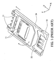
FIG. 1 . A conventional memory card fixing device for a mobile phone mainly includes afoundation 10 and a rotatingpart 20 which is pivotally connected to thefoundation 10 through apivot 21. When a user wants to place a memory card, he can make therotating part 20 slide along the Y axis and turn upward (as shown by the arrow direction inFIG. 1 ). Then, the memory card can be put into aslot 22 of therotating part 20, and then the rotating part is closed to make the memory card electrically connected with aconnector 11 of the mobile phone. - However, the conventional memory card fixing device has a complex design and a high cost, and the replacement of the memory card is also not convenient. Therefore, how to provide a preferred memory card fixing device becomes an important subject.
- One embodiment of the invention provides a memory card fixing device including a base and two resilient fastening structures which are provided at the two opposite sides of the base and are roughly symmetrical about a central axis of the base. Each fastening structure has a guiding portion a holding portion which forms a recess. The memory card slides into the recess along the guiding portion and is fixed in the recess via the resilience of the fastening structure.
- In one preferred embodiment, the memory card fixing device is roughly Π-shaped.
- In one preferred embodiment, the fastening structure is made of material.
- In one preferred embodiment, the base is made of material.
- In one preferred embodiment, the fastening structure and the base are integrally formed.
- In one preferred embodiment, the memory card fixing device is a stainless steel sheet.
- In one preferred embodiment, each fastening structure further includes a bearing portion which is connected to the base and the holding portion, wherein the bearing portion extends toward the central axis from the external side of the base to bear the memory card.
- In one preferred embodiment, each fastening structure further includes a bending portion which is connected to the guiding portion and the holding portion, wherein the a first opening is formed between the bending portions of the two fastening structures, and the width of the first opening is less than the width of the memory card.
- In one preferred embodiment of the invention, a second opening is formed between the bearing portions of the two fastening structures, and the width of the second opening is less than the width of the first opening.
- The invention provides a memory card fixing device which not only has advantages such as low costs and convenient to use, but also can be widely applied to mobile phones or other electronic devices with memory cards.
- These and other features, aspects, and advantages of the present invention will become better understood with regard to the following description, appended claims, and accompanying drawings.
-
-
FIG. 1 is a schematic diagram showing a conventional memory card fixing device for a mobile phone; -
FIG. 2 is a schematic diagram showing a memory card fixing device according to an embodiment of the invention; -
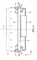
FIG. 3 is a schematic diagram showing a memory card electrically connected to a connector; and -
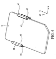
FIG. 4 is a schematic diagram showing a memory card fixed in the memory card fixing device. - Please refer to
FIG. 2 andFIG. 3 simultaneously. The memorycard fixing device 40 of the embodiment can be provided in a mobile phone to fix a memory card S in a mobile phone and make the memory card S electrically connected to aconnector 30 in the mobile phone (as shown inFIG. 3 ). The memory card S in the embodiment is, for example, a subscriber identity module (SIM) card. - As shown in
FIG. 2 , the memorycard fixing device 40 is, for example, an integrally formed stainless steel sheet and mainly includes abase 41 and tworesilient fastening structures 42. The twofastening structures 42 are roughly symmetrical about a central axis C of thebase 41 and extend upward from the two sides of thebase 41, respectively, to make the memorycard fixing device 40 be Π-shaped roughly. However, thebase 41 and thefastening structures 42 also can be made of other metals or flexible material besides the stainless steel. In addition, thebase 41 and thefastening structure 42 can be connected to each other in a sticking manner or in an assembling manner to form the memorycard fixing device 40. - In
FIG. 2 , eachfastening structure 42 has a guidingportion 43, abending portion 44, aholding portion 45 and abearing portion 46, respectively. Thebending portion 44 is connected to the guidingportion 43 and theholding portion 45. Thebearing portion 46 is connected to thebase 41 and theholding portion 45, wherein thebearing portion 46 extends toward the central axis C from the external side of thebase 41 to support the memory card S. A first opening 44' is formed between thebending portions 44 of the twofastening structures 42, and a second opening 46' is formed between the bearing portions 46' of the twofastening structures 42, wherein the width W2 of the second opening 46' is less than the width W1 of the first opening 44'. - Please refer to
FIG. 3 . In the embodiment, the memorycard fixing device 40 is fixedly connected to aconnector 30 in a mobile phone. When the memory card S needs to be placed, it can be pressed downward from the upper side of the memorycard fixing device 40. Since the width of the first opening 44' is slightly less than the width of the memory card S, the memory card contacts with the guidingportions 43 and makes the twofastening structures 42 open outward (as shown by the arrow direction inFIG. 3 ) in the process of pressing the memory card. The memory card S can slides into the recess 45' formed by theholding portion 45 along the inclined plane of the guidingportions 43. The memory card S can be fixed in the recess 45' formed by theholding portion 45 via the resilience of the right and left two fastening structures 42 (as shown inFIG.4 ), so that the memory card S can be electrically connected to theconnector 30 steadily. On the contrary, when the memory card S needs to be taken out, a user can manually make the right and left twofastening structures 42 open outward to make the width W1 of the first opening 44' slightly greater than the width of the memory card S. At that moment, thebearing portions 46 at the bottom side of the recess 45' can push the memory card S out of the first opening 44' upward to make the memory card S separated from the memorycard fixing device 40. - To sum up, the embodiment invention provides a memory card fixing device which not only has advantages such as low cost and convenient to use, but also can be widely applied to mobile phones or other electronic devices with memory cards.
- Although the present invention has been described in considerable detail with reference to certain preferred embodiments thereof, the disclosure is not for limiting the scope of the invention. Persons having ordinary skill in the art may make various modifications and changes without departing from the scope and spirit of the invention. Therefore, the scope of the appended claims should not be limited to the description of the preferred embodiments described above.
Claims (15)
- A memory card fixing device characterized by:a base 41; andtwo resilient fastening structures 42 connected to the two opposite sides of the base 41, wherein each of the fastening structures 42 has a guiding portion 43 and a holding portion 45 which forms a recess 45', and a memory card S slides into the recess 45'along the guiding portion 43 and is fixed in the recess 45' via the resilience of the fastening structure 42.
- The memory card fixing device according to claim 1, characterized in that the memory card S fixing device is roughly Π-shaped.
- The memory card fixing device according to claim 1, characterized in that the fastening structures 42 are made of metal.
- The memory card fixing device according to claim 1, characterized in that the base 41 is made of metal.
- The memory card fixing device according to claim 1, characterized in that the fastening structures 42 and the base 41 are integrally formed.
- The memory card fixing device according to claim 1, characterized in that each of the fastening structures 42 further has a bearing portion 46 connected to the base 41 and the holding portion 45 to support the memory card S.
- The memory card fixing device according to claim 6, characterized in that each of the fastening structures 42 further has a bending portion 44 connected to the guiding portion 43 and the holding portion 45, and a first opening is formed between the bending portions 44 of the fastening structures 42, and the width of the first opening is less than the width of the memory card S.
- The memory card fixing device according to claim 7 , characterized in that a second opening is formed between the bearing portions 46 of the fastening structures 42, and the width of the second opening is less than the width of the first opening.
- The memory card fixing device according to claim 1, characterized in that the memory card S is a subscriber identity module (SIM) card.
- A mobile phone characterized by:a memory card S fixing device comprising:a base 41; andtwo resilient fastening structures 42 connected to the two opposite sides of the base 41, wherein each of the fastening structures 42 has a guiding portion 43 and a holding portion 45 which forms a recess45', and a memory card S slides into the recess 45'along the guiding portion 43 and is fixed in the recess 45'via the resilience of the fastening structure 42.
- The mobile phone according to claim 10, characterized in that the memory card S fixing device is roughly Π-shaped.
- The mobile phone according to claim 10, characterized in that the fastening structures 42 and the base 41 are integrally formed.
- The mobile phone according to claim 10, characterized in that each of the fastening structures further 42 has a bearing portion 46 connected to the base 41 and the holding portion 45 to support the memory card S.
- The mobile phone according to claim 13, characterized in that each of the fastening structures 42 further has a bending portion 44 connected to the guiding portion 43 and the holding portion 45, and a first opening is formed between the bending portions 44 of the fastening structures42, and the width of the first opening is less than the width of the memory card.
- The mobile phone according to claim 14, characterized in that a second opening is formed between the bearing portions 46 of the fastening structures 42, and the width of the second opening is less than the width of the first opening.
Applications Claiming Priority (1)
| Application Number | Priority Date | Filing Date | Title |
|---|---|---|---|
| TW096133222A TWI335788B (en) | 2007-09-06 | 2007-09-06 | Mobile phones and memory card fixing devices |
Publications (2)
| Publication Number | Publication Date |
|---|---|
| EP2034424A1 true EP2034424A1 (en) | 2009-03-11 |
| EP2034424B1 EP2034424B1 (en) | 2013-01-23 |
Family
ID=39776380
Family Applications (1)
| Application Number | Title | Priority Date | Filing Date |
|---|---|---|---|
| EP08015723A Active EP2034424B1 (en) | 2007-09-06 | 2008-09-05 | Mobile phone and memory card fixing device thereof |
Country Status (3)
| Country | Link |
|---|---|
| US (1) | US7794260B2 (en) |
| EP (1) | EP2034424B1 (en) |
| TW (1) | TWI335788B (en) |
Cited By (1)
| Publication number | Priority date | Publication date | Assignee | Title |
|---|---|---|---|---|
| WO2011030176A1 (en) * | 2009-09-09 | 2011-03-17 | Sandisk Il Ltd. | Holders for portable memory cards and method for manufacturing same |
Families Citing this family (3)
| Publication number | Priority date | Publication date | Assignee | Title |
|---|---|---|---|---|
| TWI405073B (en) * | 2010-04-14 | 2013-08-11 | Aopen Inc | Fixing mechanism for fixing a portable device and related computer system |
| JP6140963B2 (en) * | 2012-09-27 | 2017-06-07 | キヤノン株式会社 | Cartridge and image forming apparatus |
| JP6308386B2 (en) * | 2014-04-09 | 2018-04-11 | 第一精工株式会社 | Wiring plate member connection device |
Citations (3)
| Publication number | Priority date | Publication date | Assignee | Title |
|---|---|---|---|---|
| US6250934B1 (en) * | 1998-06-23 | 2001-06-26 | Intel Corporation | IC package with quick connect feature |
| GB2360640A (en) | 2000-03-14 | 2001-09-26 | Sagem | Connector for smart card |
| JP2005135305A (en) * | 2003-10-31 | 2005-05-26 | Kyocera Corp | Card fixing device and portable terminal using the same |
Family Cites Families (5)
| Publication number | Priority date | Publication date | Assignee | Title |
|---|---|---|---|---|
| US1744979A (en) * | 1927-05-18 | 1930-01-28 | Weis Mfg Company | Visible index system |
| JP3850812B2 (en) * | 2003-05-23 | 2006-11-29 | 三和電気工業株式会社 | Memory card adapter |
| CN1311398C (en) | 2003-06-04 | 2007-04-18 | 三和电气工业株式会社 | Adapter for memory card |
| CN2735666Y (en) | 2004-10-15 | 2005-10-19 | 康佳集团股份有限公司 | A SIM card slot arrangement having elastic structure |
| CN1882227B (en) * | 2005-06-18 | 2010-04-07 | 深圳富泰宏精密工业有限公司 | Holding structure of chip card |
-
2007
- 2007-09-06 TW TW096133222A patent/TWI335788B/en active
-
2008
- 2008-09-04 US US12/204,787 patent/US7794260B2/en active Active
- 2008-09-05 EP EP08015723A patent/EP2034424B1/en active Active
Patent Citations (3)
| Publication number | Priority date | Publication date | Assignee | Title |
|---|---|---|---|---|
| US6250934B1 (en) * | 1998-06-23 | 2001-06-26 | Intel Corporation | IC package with quick connect feature |
| GB2360640A (en) | 2000-03-14 | 2001-09-26 | Sagem | Connector for smart card |
| JP2005135305A (en) * | 2003-10-31 | 2005-05-26 | Kyocera Corp | Card fixing device and portable terminal using the same |
Cited By (2)
| Publication number | Priority date | Publication date | Assignee | Title |
|---|---|---|---|---|
| WO2011030176A1 (en) * | 2009-09-09 | 2011-03-17 | Sandisk Il Ltd. | Holders for portable memory cards and method for manufacturing same |
| US8720682B2 (en) | 2009-09-09 | 2014-05-13 | Sandisk Il Ltd. | Holders for portable memory cards and methods for manufacturing same |
Also Published As
| Publication number | Publication date |
|---|---|
| EP2034424B1 (en) | 2013-01-23 |
| US20090068874A1 (en) | 2009-03-12 |
| TWI335788B (en) | 2011-01-01 |
| TW200913856A (en) | 2009-03-16 |
| US7794260B2 (en) | 2010-09-14 |
Similar Documents
| Publication | Publication Date | Title |
|---|---|---|
| US8050030B2 (en) | Electronic device | |
| US8308514B1 (en) | SIM card holder | |
| US7442086B1 (en) | Chip card retaining mechanism | |
| CN101685932B (en) | Chip card fixedly holding structure | |
| US20100069118A1 (en) | Modular Structure to Expand and Enhance Subscriber Identity Module Card Functionality | |
| JP2001244004A (en) | Card holding structure and portable terminal equipped with the same | |
| US20100259906A1 (en) | Sim card retention assembly | |
| JP2008522317A (en) | SIM card holding device | |
| US7794260B2 (en) | Mobile phone and memory card fixing device thereof | |
| JP2005166286A (en) | Card holding structure of portable electronic apparatus | |
| US7354290B2 (en) | Surface contact card holder | |
| US6761591B1 (en) | SIM card receiving mechanism | |
| CN106463862B (en) | Card slot for electronic device | |
| US7495926B2 (en) | Interface module for electronic devices | |
| US11018468B2 (en) | Card tray, card tray plug-in device, and terminal | |
| WO2021078049A1 (en) | Electronic device, card support, and card holder | |
| US7097511B1 (en) | Structure for SIM card assembly and disassembly | |
| CN101001091A (en) | Chip card fastening structure | |
| CN101383856B (en) | Mobile phone and its memory card fixing device | |
| CA2551377C (en) | Structure for sim card assembly and disassembly | |
| TWI345344B (en) | Sim card holding structure | |
| JP4662884B2 (en) | Card storage structure and electronic device | |
| TW574813B (en) | Implement for fixed a SIM card | |
| US20130280939A1 (en) | Surface contact card holder for electronic device | |
| US20150055314A1 (en) | Mounting assembly for chip card and portable electronic device using same |
Legal Events
| Date | Code | Title | Description |
|---|---|---|---|
| PUAI | Public reference made under article 153(3) epc to a published international application that has entered the european phase |
Free format text: ORIGINAL CODE: 0009012 |
|
| AK | Designated contracting states |
Kind code of ref document: A1 Designated state(s): AT BE BG CH CY CZ DE DK EE ES FI FR GB GR HR HU IE IS IT LI LT LU LV MC MT NL NO PL PT RO SE SI SK TR |
|
| AX | Request for extension of the european patent |
Extension state: AL BA MK RS |
|
| 17P | Request for examination filed |
Effective date: 20090406 |
|
| AKX | Designation fees paid |
Designated state(s): DE FR GB |
|
| GRAP | Despatch of communication of intention to grant a patent |
Free format text: ORIGINAL CODE: EPIDOSNIGR1 |
|
| GRAS | Grant fee paid |
Free format text: ORIGINAL CODE: EPIDOSNIGR3 |
|
| GRAA | (expected) grant |
Free format text: ORIGINAL CODE: 0009210 |
|
| AK | Designated contracting states |
Kind code of ref document: B1 Designated state(s): DE FR GB |
|
| REG | Reference to a national code |
Ref country code: GB Ref legal event code: FG4D |
|
| REG | Reference to a national code |
Ref country code: DE Ref legal event code: R096 Ref document number: 602008021811 Country of ref document: DE Effective date: 20130321 |
|
| PLBE | No opposition filed within time limit |
Free format text: ORIGINAL CODE: 0009261 |
|
| STAA | Information on the status of an ep patent application or granted ep patent |
Free format text: STATUS: NO OPPOSITION FILED WITHIN TIME LIMIT |
|
| 26N | No opposition filed |
Effective date: 20131024 |
|
| REG | Reference to a national code |
Ref country code: DE Ref legal event code: R097 Ref document number: 602008021811 Country of ref document: DE Effective date: 20131024 |
|
| REG | Reference to a national code |
Ref country code: FR Ref legal event code: PLFP Year of fee payment: 9 |
|
| REG | Reference to a national code |
Ref country code: FR Ref legal event code: PLFP Year of fee payment: 10 |
|
| REG | Reference to a national code |
Ref country code: FR Ref legal event code: PLFP Year of fee payment: 11 |
|
| P01 | Opt-out of the competence of the unified patent court (upc) registered |
Effective date: 20230428 |
|
| PGFP | Annual fee paid to national office [announced via postgrant information from national office to epo] |
Ref country code: FR Payment date: 20250623 Year of fee payment: 18 |
|
| PGFP | Annual fee paid to national office [announced via postgrant information from national office to epo] |
Ref country code: DE Payment date: 20250624 Year of fee payment: 18 |
|
| PGFP | Annual fee paid to national office [announced via postgrant information from national office to epo] |
Ref country code: GB Payment date: 20250701 Year of fee payment: 18 |