EP2034423B1 - Smart cables - Google Patents
Smart cables Download PDFInfo
- Publication number
- EP2034423B1 EP2034423B1 EP08015543.5A EP08015543A EP2034423B1 EP 2034423 B1 EP2034423 B1 EP 2034423B1 EP 08015543 A EP08015543 A EP 08015543A EP 2034423 B1 EP2034423 B1 EP 2034423B1
- Authority
- EP
- European Patent Office
- Prior art keywords
- cable
- authentication
- identification
- micro
- controller
- Prior art date
- Legal status (The legal status is an assumption and is not a legal conclusion. Google has not performed a legal analysis and makes no representation as to the accuracy of the status listed.)
- Active
Links
- 238000000034 method Methods 0.000 claims description 129
- 230000008569 process Effects 0.000 claims description 70
- 230000004044 response Effects 0.000 claims description 37
- 238000004891 communication Methods 0.000 claims description 17
- 238000012545 processing Methods 0.000 claims description 16
- 239000002131 composite material Substances 0.000 description 16
- 238000012360 testing method Methods 0.000 description 15
- 238000010586 diagram Methods 0.000 description 5
- 230000005236 sound signal Effects 0.000 description 5
- 238000001514 detection method Methods 0.000 description 4
- 238000012986 modification Methods 0.000 description 3
- 230000004048 modification Effects 0.000 description 3
- 230000002093 peripheral effect Effects 0.000 description 3
- 230000008901 benefit Effects 0.000 description 2
- 230000007246 mechanism Effects 0.000 description 2
- 238000013459 approach Methods 0.000 description 1
- 238000013475 authorization Methods 0.000 description 1
- 238000010276 construction Methods 0.000 description 1
- 230000000977 initiatory effect Effects 0.000 description 1
- 238000012795 verification Methods 0.000 description 1
Images


Classifications
-
- H—ELECTRICITY
- H01—ELECTRIC ELEMENTS
- H01R—ELECTRICALLY-CONDUCTIVE CONNECTIONS; STRUCTURAL ASSOCIATIONS OF A PLURALITY OF MUTUALLY-INSULATED ELECTRICAL CONNECTING ELEMENTS; COUPLING DEVICES; CURRENT COLLECTORS
- H01R29/00—Coupling parts for selective co-operation with a counterpart in different ways to establish different circuits, e.g. for voltage selection, for series-parallel selection, programmable connectors
-
- G—PHYSICS
- G06—COMPUTING; CALCULATING OR COUNTING
- G06F—ELECTRIC DIGITAL DATA PROCESSING
- G06F13/00—Interconnection of, or transfer of information or other signals between, memories, input/output devices or central processing units
-
- G—PHYSICS
- G06—COMPUTING; CALCULATING OR COUNTING
- G06F—ELECTRIC DIGITAL DATA PROCESSING
- G06F13/00—Interconnection of, or transfer of information or other signals between, memories, input/output devices or central processing units
- G06F13/14—Handling requests for interconnection or transfer
- G06F13/20—Handling requests for interconnection or transfer for access to input/output bus
-
- G—PHYSICS
- G06—COMPUTING; CALCULATING OR COUNTING
- G06F—ELECTRIC DIGITAL DATA PROCESSING
- G06F13/00—Interconnection of, or transfer of information or other signals between, memories, input/output devices or central processing units
- G06F13/38—Information transfer, e.g. on bus
-
- G—PHYSICS
- G06—COMPUTING; CALCULATING OR COUNTING
- G06F—ELECTRIC DIGITAL DATA PROCESSING
- G06F13/00—Interconnection of, or transfer of information or other signals between, memories, input/output devices or central processing units
- G06F13/38—Information transfer, e.g. on bus
- G06F13/382—Information transfer, e.g. on bus using universal interface adapter
- G06F13/385—Information transfer, e.g. on bus using universal interface adapter for adaptation of a particular data processing system to different peripheral devices
-
- G—PHYSICS
- G06—COMPUTING; CALCULATING OR COUNTING
- G06F—ELECTRIC DIGITAL DATA PROCESSING
- G06F21/00—Security arrangements for protecting computers, components thereof, programs or data against unauthorised activity
- G06F21/30—Authentication, i.e. establishing the identity or authorisation of security principals
- G06F21/44—Program or device authentication
-
- G—PHYSICS
- G06—COMPUTING; CALCULATING OR COUNTING
- G06F—ELECTRIC DIGITAL DATA PROCESSING
- G06F3/00—Input arrangements for transferring data to be processed into a form capable of being handled by the computer; Output arrangements for transferring data from processing unit to output unit, e.g. interface arrangements
-
- H—ELECTRICITY
- H01—ELECTRIC ELEMENTS
- H01R—ELECTRICALLY-CONDUCTIVE CONNECTIONS; STRUCTURAL ASSOCIATIONS OF A PLURALITY OF MUTUALLY-INSULATED ELECTRICAL CONNECTING ELEMENTS; COUPLING DEVICES; CURRENT COLLECTORS
- H01R13/00—Details of coupling devices of the kinds covered by groups H01R12/70 or H01R24/00 - H01R33/00
- H01R13/66—Structural association with built-in electrical component
- H01R13/665—Structural association with built-in electrical component with built-in electronic circuit
- H01R13/6691—Structural association with built-in electrical component with built-in electronic circuit with built-in signalling means
-
- H—ELECTRICITY
- H01—ELECTRIC ELEMENTS
- H01R—ELECTRICALLY-CONDUCTIVE CONNECTIONS; STRUCTURAL ASSOCIATIONS OF A PLURALITY OF MUTUALLY-INSULATED ELECTRICAL CONNECTING ELEMENTS; COUPLING DEVICES; CURRENT COLLECTORS
- H01R9/00—Structural associations of a plurality of mutually-insulated electrical connecting elements, e.g. terminal strips or terminal blocks; Terminals or binding posts mounted upon a base or in a case; Bases therefor
- H01R9/22—Bases, e.g. strip, block, panel
- H01R9/24—Terminal blocks
- H01R9/2475—Means facilitating correct wiring, e.g. marking plates, identification tags
Definitions
- the present invention relates in general to electronic cables. More particularly, the invention relates to smart cables that can provide additional functionality such as identification and authentication.
- electronic products such as mobile phones, personal digital assistants (PDAs), media players, CD players, DVD players, televisions, game players, digital cameras and the like invariably include connectors for making connection to other electronic devices via cables.
- the different types of connectors may include electrical contacts to carry various types of signals such as digital or analog audio and/or video signals, USB, Firewire, etc.
- Examples of media devices with a highly versatile connector system are the iPod and the iPhone manufactured by Apple Inc. of Cupertino, California. These media devices may communicate with their accessories and other peripheral devices through one or more cable apparatus. For example, the media devices can send audio signals to a speaker, and/or send video signals to a computer display or television. In order to transmit various kinds of signals, different types of cables may be used. Different cables may have different performance characteristics and may be designed to operate with different communication protocols. Such information often needs to be efficiently communicated to the media devices. Hence it is highly desirable to improve electronic cabling techniques for media devices.
- the US patent application US 2007/0117444 A1 describes a smart patch cord having a patch panel plug and a switch plug.
- the patch panel plug plugs into a signal port of an intelligent patch panel, and the switch plug plugs into a network switch (such as an Ethernet switch), thereby providing communication between the panel and the network switch.
- Plug detection circuitry and ID circuitry are housed in switch plug.
- the ID circuitry receives a request from the panel and responds with an ID number.
- the intelligent patch panel works by having the cord provisioned using a provisioning port and then having the cord then plugged into one of the signal ports.
- the US patent application US 2006/0156415 A1 discloses improved techniques to control utilization of accessory devices with electronic devices.
- the improved techniques can use cryptographic approaches to authenticate electronic devices, namely, electronic devices that interconnect and communicate with one another.
- One aspect pertains to techniques for authenticating an electronic device, such as an accessory device.
- Another aspect pertains to provisioning software features (e.g., functions) by or for an electronic device (e.g., a host device). Different electronic devices can, for example, be provisioned differently depending on different degrees or levels of authentication, or depending on manufacturer or product basis.
- Still another aspect pertains to using an accessory (or adapter) to convert a peripheral device (e.g., USB device) into a host device (e.g., USB host).
- a peripheral device e.g., USB device
- host device e.g., USB host
- the improved techniques are particularly well suited for electronic devices, such as media devices, that can receive accessory devices.
- a media device is a media player, such as a hand-held media player (e.g., music player), that can present (e.g., play) media items (or media assets).
- the PCT patent application WO 2004/001552 A2 discloses an identification system and method for recognizing a device as one of a plurality of different types of devices connected to at least one terminal of an information handling system, including supplying a test signal to a device in a test mode; measuring an electrical characteristic of the device in response to the test signal being applied to the device in the test mode; and matching a representation of the electrical characteristic of the device with representations of the electrical characteristics of the plurality of devices for recognizing the device connected to the terminal as one of the plurality of different devices. It describes providing a test signal to a device and then detecting the response signal to identify the device. It may imply that a cable exists, but the identification of an accessory does not provide an identification of the cable type that is used.
- the US patent application US 2003/0053603 A1 provides a system for and method of detecting a connection of a text telephony (TTY) device to communication device, such as, a mobile telephone.
- the communication device provides a TTY bearer bit to its communication network upon detecting that a TTY device is connected to it.
- the connection between the communication device and the TTY device can be made using a smart cable or a connector cable.
- the detection that a TTY device is connected to the communication device is automatic and does not require the user of the communication device to enter a code or any other input to the communication device.
- it is the mobile device which performs the detection, not the cable.
- the mobile device detects the existence of a cable, not the type of a cable.
- the mobile device detects a resistor value in another connector via I/O pins in the mobile device
- the US patent application US 2005/182876 discloses a cable device that is able to perform a conventional HDCP, High-bandwidth Digital Content Protection System, verification with a transmitter device.
- a microcontroller and an authentication co-processor performing an authentication algorithm within a cable connector are not mentioned.
- a cabling apparatus includes circuitry that can communicate with another device information about the cable including, for example, whether the cable is an authorized cable, what type of cable it is, what type or types of signal(s) it can carry, etc. If the cable is, for example, a composite video or a component video cable connecting a media device to a display, circuitry incorporated in the cable apparatus, according to one embodiment of the present invention, can identify itself and can instruct the media device to supply the display with the appropriate composite or component video signal.
- the various embodiments of the invention are described in the context of media devices, but it should be recognized that the invention has broader range of applicability.
- a cable apparatus may include a first connector including a housing, a plurality of contacts, and one or more processing components. Additionally, the cable apparatus may include a cable having a first end coupled to the first connector and a second end coupled to one or more second connectors. The one or more second connectors can be configured to connect with one or more electronic devices. The one or more processing components of the cable apparatus can be configured to receive an authentication inquiry from an electronic device through the plurality of contacts, generate an authentication response, and output the authentication response to the electronic device through the plurality of contacts. The authentication response may be associated with whether the cable apparatus is an authorized accessory for the electronic device.
- a cable apparatus may include a first connector including a housing, a plurality of contacts, and one or more processing components. Additionally, the cable apparatus may include a cable having a first end coupled to the first connector and a second end coupled to one or more second connectors. The one or more second connectors can be configured to be coupled to one or more electronic devices respectively. The one or more processing components can be configured to identify a type of the cable apparatus, generate a cable identification signal, and output the identification signal to the electronic device through the plurality of contacts. The identification signal may be associated with one or more types of signals to be carried by the cable apparatus.
- a method for operating a cable apparatus includes providing the cable apparatus with circuitry to implement a cable identification process, the cable circuitry to be powered upon connection of the cable apparatus to another electronic device.
- the method includes the cable circuitry identifying the type of cable and generating a cable identification signal, and the cable circuitry transmitting the cable identification signal to the electronic device.
- the process of identifying the type of cable may include detecting a signal level on node in the cable circuitry.
- the process of identifying the type of cable may include transmitting one or more test signals to predetermined contacts coupled to the cable apparatus.
- a method for operating a cable apparatus includes providing the cable apparatus with circuitry to implement a cable authentication process, the cable circuitry to be powered upon connection of the cable apparatus to another electronic device.
- the method includes the cable circuitry receiving an authentication request from the electronic device and performing an authentication process.
- the cable circuitry then generating a cable authentication signal and transmitting the cable identification signal to the electronic device.
- a method of operating a cable apparatus may include receiving an authentication inquiry by a cable apparatus from an electronic device, processing the authentication inquiry by the cable apparatus, sending an authentication response from the cable apparatus to the electronic device, receiving an identification inquiry by the cable apparatus from the electronic device, identifying a cable type for the cable apparatus by the cable apparatus, and sending an identification signal based on at least information associated with the identified cable type.
- the authentication response can be associated with whether the cable apparatus is an authorized accessory for the electronic device, and the identification signal can be associated with one or more types of signals related to the cable apparatus.
- FIG. 1 illustrates a simplified cable apparatus according to an exemplary embodiment of the present invention that is capable of communicating information such as cable identification and authentication upon connection to another device.
- Cable apparatus 100 may include connector 110 at one end, one or more connector ends 120 at another end, and cable 130 as well as one or more cable lines 140 that couple the connector ends of the cable apparatus.
- Connector 110 may include contact housing 112 which encloses a plurality of electrical contacts (not shown), and connector boot 114 which houses the assembly that connects wires from the cable lines to the electrical contacts.
- Within connector boot 114 there can also be electronic components (not shown) that are configured to perform electrical functionality such as cable authentication, cable identification, electrostatic discharge protection and the like.
- PCB printed circuit board
- Plurality of cable lines 140 may be configured to carry a respective plurality of signals, each line connecting to at least one of plurality of connectors 120.
- plurality of connectors 120 may include at least an audio connector, a video connector, and/or a USB connector.
- the circuitry that may be integrated inside boot 114 of connector 110 can be configured to identify the type of cable and transmit that information (i.e., that the cable is a composite video cable) to the device to which it connects.
- the device could be, for example, a media device such as an iPod or an iPhone.
- the media device then automatically provides the appropriate signal, i.e., composite video signal, to the cable.
- Cable apparatus 100 can provide any one or more of the other types of cables and signals that media devices such as the iPod support, including analog audio, digital (USB) audio, component video, HDMI, DVI, S-video, etc.
- each line 140 may include one or more lines, each of which can independently carry one or more signals.
- cable lines 140 may include only one line that is combined with cable 130 to form a single cable.
- one or more additional components may be added to those noted above.
- the specific arrangement of components may be interchanged. Further details of the various arrangements and cabling components can be found throughout the present specification below.
- FIG. 2 illustrates a high level block diagram for connector 110 in cable apparatus 100 according to an exemplary embodiment of the present invention.
- connector 110 may include a contact housing 112 and a connector boot 114.
- connector boot 114 houses a PCB (not shown) on which various circuit components can be mounted.
- the circuit components can include, for example, micro-controller 210, authentication coprocessor 220, and identification wire 230 that may be electrically coupled together via circuit traces on the PCB.
- An example of the internal construction of connector 100 can be found in the above-referenced patent application number 11/650,330 (Attorney Docket No.
- micro-controller 210 can be primarily responsible for controlling communication to and from the media device via bus 240.
- Authentication coprocessor 220 can be primarily responsible for implementing the authentication functionality.
- identification wire 230 can be used by micro-controller 210 to detect the type of signal the cable is configured to carry (e.g., component video or composite video).
- a bus 250 can connect the wires from cable 130 to the contacts (or pins) in contact housing 112.
- the term bus refers to any mechanism that electrically connects one set of contact points to another and is not limited to any specific type of electro-mechanical means.
- the media device may send an authentication inquiry to the cable.
- Micro-controller 210 can receive the authentication inquiry and communicate it to authentication coprocessor 220.
- Authentication coprocessor 220 then processes the authentication request using an authentication algorithm.
- the authentication algorithm can be based on, for example, public key encryption using security certificates, digital signatures or other known authentication methodologies.
- authentication techniques similar to those described in commonly-assigned U.S. Patent Application Number 11/051,499 , (Attorney Docket No. 20750P-001110/P3503US1) titled "Accessory Authentication For Electronic Devices,” can be implemented by authentication coprocessor 220.
- the result of the authentication process is communicated from authentication coprocessor 220 to micro-controller 210 and from micro-controller 210 to the media device via bus 240.
- the media device may proceed with further communication with the cable apparatus. While the block diagram of Figure 2 shows micro-controller 210 and authentication coprocessor 220 as two separate components, it is possible to integrate both functionalities into a single chip.
- a signal such as a voltage level provided on identification wire 230 indicates a type of cable.
- the signal on identification wire 230 can, for example, indicate whether the cable is configured to carry, e.g., composite video, component video or S-video signal.
- the level of the signal on identification wire 230 can be set by, for example, a resistive circuit that may be coupled either to the power supply (i.e., as a pull-up) or to ground (i.e., as a pull-down) or between both to form a voltage divider. It is also possible to not connect identification wire 230 to any signal and instead use a floating condition to also indicate a type of cable.
- micro-controller 210 determines the type of cable it is associated with, it may internally save that information in a register so that it does not have to make that determination each time it is connected to a media device. Once the cable type is identified (and in some embodiments after the cable is authenticated), micro-controller 210 can transmit a request signal to a media device to which it is connected to enable the appropriate (e.g., audio and/or video) outputs in the correct format. While in this example, the type of cable is determined based on voltage level on identification wire 230, it is also possible to accomplish similar functionality with techniques other than voltage level detection, such as current sensing.
- a more sophisticated micro-controller 210 can eliminate the need for identification wire 230 and its associated circuitry by dynamically detecting the type of cable being used.
- micro-controller 210 can be programmed to detect the type of cable upon connection between the media device and an accessory device.
- Figure 3 depicts cable apparatus 100 connecting a media device 310 to one or more accessory devices 320. Connector end 110 of cable apparatus 100 connects to media device 310 via contacts 112 while any one or more of connector ends 120 connect to one or more accessory devices 320.
- micro-controller 210 can test whether a connection is made at the accessory end via any one or more of cables 140. This can be done, for example, by micro-controller 210 applying one or more test signals to pre-determined contact pins 112 that are designated to carry specific signal types when connected by cable apparatus 100 to one or more accessory devices 320. In an alternative embodiment, micro-controller 210 can apply the test signals directly to pre-determined wires in cable 130 via bus 260 (see Figure 2 ). Based on the signal(s) returned to micro-controller 210 in response to the test signal(s), the micro-controller can determine how many and which connector end(s) 120 are in fact connected to an accessory. This will enable micro-controller 210 to identify the type of cable being used.
- micro-controller 210 For example, if only one connector end 120, such as a male RCA plug for a single composite video cable, is connected, micro-controller 210 will identify the cable as a composite video cable. If, on the other hand, the test indicates connection of three connector ends 120 corresponding to component video signal, then micro-controller 210 identifies the cable as component video cable. It is also possible for micro-controller 210 to determine an erroneous connection (e.g., when only one of the three component connector ends is connected) and signal media device 310 to indicate the erroneous connection on its display. Accordingly, in this embodiment, the cable type is determined by the connection it is providing and therefore can vary from one application to the next.
- micro-controller 210 will identify the cable type as composite video cable.
- the same cable when used in another application for connecting a media device to, for example, a video accessory that uses component video will be identified by micro-controller 210 as a component video.
- micro-controller 210 can transmit the cable preferences for that particular cable type to the media device.
- the cable preferences depend on the cable type which can be any one or more of the following: USB, Firewire, analog or digital audio, composite video, component video, S-video, HDMI, DVI and the like.
- preferences for a composite video cable can be audio line out and composite video.
- cable apparatus 100 may be used to connect a media device such as an iPod to both a television set via video connector ends and a hi-fi speaker system via the audio connector ends.
- Cable apparatus 100 automatically performs the authentication process upon connection to media device 310.
- Cable apparatus 100 can also perform the cable identification process upon connection to media device 310 or upon connection to both media device 310 and accessory devices 320.
- Micro-controller 210 can perform the cable identification task before, after or in parallel with the authentication process.
- FIGS 4 , 5 and 6 illustrate various simplified methods of operation for the smart cable according to embodiments of the present invention.
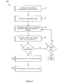
- Method 400 shown in Figure 4 depicts one authentication method which may include process 410 for powering up the cable circuitry upon connection to an electronic device such as a media player or an accessory.
- the cable circuitry may receive an authentication inquiry from the media device (process 420). It is also possible that the authentication inquiry sent from the media device to the cable circuitry may be prompted by the cable circuitry itself requesting to be authenticated.
- the cable circuitry may process the authentication inquiry and generate an authentication response (process 430). The cable circuitry may next send the authentication response back to the media device (process 440).
- the authentication response is accepted by the media device (process 450)
- cable preferences may be transmitted to the media device (process 460) and further communication via the cable apparatus may be authorized (process 470). If the authentication process fails, the cable may be assumed to be unauthorized and no further communication via that cable may be allowed. In one embodiment, the authorization process may be retried one or more times before the cable apparatus is rejected (process 480).
- micro-controller 210 may be powered using, for example, power supplied from media device 320 (or an accessory when connected to an accessory).
- micro-controller 210 may receive an authentication request from media device 320.
- micro-controller 210 then communicates with authentication coprocessor 220 to process the request in accordance with the authentication algorithm implemented by coprocessor 220.
- the response generated by authentication coprocessor 220 is then sent back to media device 310 via micro-controller 210. Accordingly, this method provides for a smart cable that includes all the resources to automatically go through an authentication process upon connection to a media device.
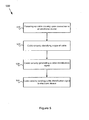
- FIG. 5 is a flow diagram depicting method 500 of cable identification according to another embodiment of the present invention.
- Method 500 may include process 510 for powering up the cable circuitry upon connection to an electronic device such as a media player or an accessory, process 520 for identifying the type of cable, process 530 for generating a cable identification signal, and process 540 for sending the cable identification signal to the media device.
- process 510 may include powering the internal circuitry of the cable including micro-controller 210 and authentication coprocessor 220 upon connecting the cable to media device 320 (or to an accessory) using, for example, power supplied from media device 320.
- process 520 may include micro-controller 210 identifying the cable type.
- the identification of cable type by process 530 may involve micro-controller 210 detecting a signal level on identification wire 230. Alternatively, micro-controller 210 can detect the cable type by the configuration in which the cable is being used and the type of accessory 320 to which it is connected.
- process 530 may include micro-controller 210 generating an identification signal and then, process 540 may include sending the identification signal to media device 310.
- the identification signal may include cable preferences.
- media device 310 may use the identification signal and automatically start transmitting audio and/or video signals to the cable apparatus 100 according to preferred or required signal formats.
- media device 310 may use the identification signal and narrow its displayed menu choices (e.g., showing only the video files that are available in component format).
- the identification signal may instruct the media device to transmit audio signals but no video signals to the cable apparatus, and/or may also specify the type of audio signals that is preferred or required by the cable apparatus.
- the identification signal may instruct the media device to transmit both audio signals and video signals to the cable apparatus.
- the identification signal may also specify the preferred or required type of audio signals, and/or specify the preferred or required type of video signals.
- the type of video signal may be composite, component, digital audio, S-video, HDMI, etc.
- the type of video signals that is preferred or required by the cable apparatus may be component video signals (e.g., Y, Pb, Pr signals). Accordingly, this method provides for a smart cable that includes all the resources to automatically identify the cable type and send cable preferences to the media device upon connection to the media device.
- component video signals e.g., Y, Pb, Pr signals.
- Figure 6 is a flow diagram depicting method 600 of cable identification and authentication according to another embodiment of the present invention.
- Method 600 essentially combines methods 400 and 500 providing for a smart cable that can automatically perform both the identification and authentication processes upon connection to a media device.
- method 600 may include process 610 for powering up the cable circuitry upon connection to a media device (or an accessory).
- the method may also include process 620 involving the cable circuitry identifying a cable type, and process 630 for the cable circuitry generating and transmitting a cable identification signal to the media device.
- method 600 may also include process 640 whereby the cable circuitry starts the authentication algorithm and generates an authentication response.
- Process 640 is followed by process 650 which may include sending the authentication response back to the media device. If the cable authentication is successful (process 660), the cable then may send its preferences to the media device (process 670) after which media content may be communicated over the cable (process 680). The cable preferences may include, for example, enabling audio and/or video line out, etc. If authentication fails, method 600 may include process 690 whereby the authentication processes (640 and 650) are repeated a predetermined number of times (n) before rejecting the cable as unauthorized.
- the identification process and or the authentication process may occur with or without an inquiry from the media device.
- the process (630) whereby the cable identifies its type to the media device may include the cable also requesting to be authenticated.
- the media device may send an authentication request signal to the cable initiating the cable authentication process.
- the various authentication processes 640 and 650 may occur before, after or concurrently with identification processes 620 and 630.
- the authentication processes 640 and 650 may occur first and, depending on the result of the authentication challenge, the remaining processes may proceed or may be halted. According to this embodiment, if the cable apparatus transmits the expected authentication response, media device 310 may confirm that the coupled cable apparatus is an authorized cable allowing further processes including the cable identification process to continue. If, however, no authentication response is received or if incorrect authentication response is received, the media device may be prevented from transmitting data through the attached cable apparatus, and subsequent processes cannot proceed.
- communication between the cable apparatus, the media device and the accessory can be based on any one of a variety of interface protocols.
- One example of such an interface protocol is the iPod Accessory Protocol developed by Apple Inc. that can facilitate communication between an iPod or iPhone and accessories via a smart cable apparatus according to the present invention.
- This particular protocol is described in greater detail in commonly assigned U.S. Patent Number 7,293,122 , entitled “Connector Interface System Facilitating Communication Between a Media Player and an Accessory,” to Schubert et al.
- one example of the type of connector suitable for connector 110 over which the above-referenced interface protocol can be communicated is described in the above-referenced patent application number 11/650,330 (Attorney Docket No.
- An exemplary embodiment of the present invention provides a cable apparatus comprising: a first connector including a housing, a plurality of contacts, and one or more processing components, the plurality of contacts being configured to couple to a first electronic device; a cable coupled to the first connector; and one or more second connectors coupled to the cable and configured to couple to one or more second electronic devices; wherein the one or more processing components are configured to identify a type of the cable apparatus, generate an identification signal, and send the identification signal to the first electronic device through the plurality of contacts, wherein the identification signal identifies what types of signals the cable apparatus can carry.
- the one or more processing components include a micro-controller coupled to an identification circuit.
- the micro-controller is further configured to detect a signal level supplied by the identification circuit and to determine the type of the cable apparatus based at least on the detected signal level.
- the signal level supplied by the identification circuit is predetermined.
- the one or more processing components include a micro-controller that is configured to determine the type of the cable apparatus based on detecting which of the one or more second connectors are connected to respective one or more second electronic devices.
- the types of signals the cable apparatus can carry can be one or more from among a plurality of signal types including composite video, component video, S-video, HDMI or other digital video formats.
- the one or more processing components are further configured to receive an authentication inquiry from a the first electronic device through the plurality of contacts, to generate an authentication response, and to send the authentication response to the first electronic device through the plurality of contacts.
- Another exemplary embodiment of the present invention provides a method for identifying a cable apparatus, the method comprising: the cable apparatus detecting a signal level on an identification wire inside the cable apparatus; the cable apparatus identifying a cable type based on the detected signal level on the identification wire; and the cable apparatus sending to an electronic device, a cable identification signal based at least in part on information associated with the identified cable type, wherein, the identification signal is associated with one or more types of signals related to the cable apparatus.
- the identification wire is coupled to a resistor.
- the identification wire is coupled to a resistor divider.
- the method further comprises the cable apparatus receiving an identification request from the electronic device.
- Another exemplary embodiment of the present invention provides a method of identifying types of electronic device coupled to a cable apparatus, the method comprising: the cable apparatus detecting a type of first electronic device to which it is connected through a first connector by applying one or more test signals to one or more pins of the first connector; the cable apparatus identifying a cable type based on one or more signals returned in response to the one or more test signals applied to the first connector; and the cable apparatus sending to a second electronic device, a cable identification signal based at least in part on information associated with the identified cable type.
- the method further comprises: the cable apparatus detecting a type of second electronic device to which it is connected through a second connector by applying one or more test signals to one or more pins of the second connector; the cable apparatus identifying a cable type based on one or more signals returned in response to the one or more test signals applied to the second connector.
- the method further comprises the cable apparatus receiving an identification request from the second electronic device.
- Another exemplary embodiment of the present invention provides a method of operating a cable apparatus, the method comprising: an identification method comprising: receiving power from an electronic device; and without receiving a request for a cable identification signal from the electronic device, sending to the electronic device a cable identification signal based at least in part on information associated with an identified cable type; wherein the identification signal is associated with one or more types of signals related to the cable apparatus; and an authentication method comprising: the cable apparatus receiving an authentication inquiry from an electronic device; the cable apparatus processing the authentication inquiry by an authentication circuitry; the authentication circuitry generating an authentication response that is associated with whether the cable apparatus is an authorized accessory for the electronic device; and the cable apparatus sending the authentication response from the cable apparatus to the electronic device.
- the identification method further comprises: the cable apparatus detecting a signal level on an identification wire inside the cable apparatus; and the cable apparatus identifying a cable type based on the detected signal level on the identification wire.
Description
- The present application is related to commonly-assigned
U.S. Patent Application Number 11/650,330U.S. Provisional Application No. 60/969,946 - The present invention relates in general to electronic cables. More particularly, the invention relates to smart cables that can provide additional functionality such as identification and authentication.
- The handheld consumer electronic market continues to grow at an extraordinary pace, and more of these products provide increasing interconnectivity with other electronic devices. By way of example, electronic products such as mobile phones, personal digital assistants (PDAs), media players, CD players, DVD players, televisions, game players, digital cameras and the like invariably include connectors for making connection to other electronic devices via cables. The different types of connectors may include electrical contacts to carry various types of signals such as digital or analog audio and/or video signals, USB, Firewire, etc.
- Examples of media devices with a highly versatile connector system are the iPod and the iPhone manufactured by Apple Inc. of Cupertino, California. These media devices may communicate with their accessories and other peripheral devices through one or more cable apparatus. For example, the media devices can send audio signals to a speaker, and/or send video signals to a computer display or television. In order to transmit various kinds of signals, different types of cables may be used. Different cables may have different performance characteristics and may be designed to operate with different communication protocols. Such information often needs to be efficiently communicated to the media devices. Hence it is highly desirable to improve electronic cabling techniques for media devices.
- The US patent application
US 2007/0117444 A1 describes a smart patch cord having a patch panel plug and a switch plug. The patch panel plug plugs into a signal port of an intelligent patch panel, and the switch plug plugs into a network switch (such as an Ethernet switch), thereby providing communication between the panel and the network switch. Plug detection circuitry and ID circuitry are housed in switch plug. The ID circuitry receives a request from the panel and responds with an ID number. The intelligent patch panel works by having the cord provisioned using a provisioning port and then having the cord then plugged into one of the signal ports. - The book with the title "Handbook of Applied Cryptography, Identification and Entity Authentication", by Menezes a et al, CRC press LLC, USA, 1 January 1997, pages 385 to 424, provides a general description of techniques for authentication. It considers techniques designed to allow one party to gain assurances that the identity of another is as declared, thereby preventing impersonation.
- The US patent application
US 2006/0156415 A1 discloses improved techniques to control utilization of accessory devices with electronic devices. The improved techniques can use cryptographic approaches to authenticate electronic devices, namely, electronic devices that interconnect and communicate with one another. One aspect pertains to techniques for authenticating an electronic device, such as an accessory device. Another aspect pertains to provisioning software features (e.g., functions) by or for an electronic device (e.g., a host device). Different electronic devices can, for example, be provisioned differently depending on different degrees or levels of authentication, or depending on manufacturer or product basis. Still another aspect pertains to using an accessory (or adapter) to convert a peripheral device (e.g., USB device) into a host device (e.g., USB host). The improved techniques are particularly well suited for electronic devices, such as media devices, that can receive accessory devices. One example of a media device is a media player, such as a hand-held media player (e.g., music player), that can present (e.g., play) media items (or media assets). - The
PCT patent application WO 2004/001552 A2 - The US patent application
US 2003/0053603 A1 provides a system for and method of detecting a connection of a text telephony (TTY) device to communication device, such as, a mobile telephone. The communication device provides a TTY bearer bit to its communication network upon detecting that a TTY device is connected to it. The connection between the communication device and the TTY device can be made using a smart cable or a connector cable. The detection that a TTY device is connected to the communication device is automatic and does not require the user of the communication device to enter a code or any other input to the communication device. In this document, it is the mobile device which performs the detection, not the cable. Also, the mobile device detects the existence of a cable, not the type of a cable. Also, the mobile device detects a resistor value in another connector via I/O pins in the mobile device - The US patent application
US 2005/182876 , discloses a cable device that is able to perform a conventional HDCP, High-bandwidth Digital Content Protection System, verification with a transmitter device. A microcontroller and an authentication co-processor performing an authentication algorithm within a cable connector are not mentioned. - The standard document "High-bandwidth Digital Content Protection System, Revision 1.0", EPO reference XP002305414, specifies the standard HDCP authentication mechanism but does not mention an authentication co-processor within a cable in that context.
- International Patent application
WO 2008/118616 A1 discloses a cryptographic authentication of an adapter cable device. An authentication co-processor and authentication inquiry from an external device are not mentioned. - The present invention is defined in the appended independent claims.
- The present invention relates to smart cables that incorporate functionality to provide information such as identification and authentication to devices to which they connect. In various embodiments, a cabling apparatus includes circuitry that can communicate with another device information about the cable including, for example, whether the cable is an authorized cable, what type of cable it is, what type or types of signal(s) it can carry, etc. If the cable is, for example, a composite video or a component video cable connecting a media device to a display, circuitry incorporated in the cable apparatus, according to one embodiment of the present invention, can identify itself and can instruct the media device to supply the display with the appropriate composite or component video signal. The various embodiments of the invention are described in the context of media devices, but it should be recognized that the invention has broader range of applicability.
- According to one embodiment of the present invention, a cable apparatus may include a first connector including a housing, a plurality of contacts, and one or more processing components. Additionally, the cable apparatus may include a cable having a first end coupled to the first connector and a second end coupled to one or more second connectors. The one or more second connectors can be configured to connect with one or more electronic devices. The one or more processing components of the cable apparatus can be configured to receive an authentication inquiry from an electronic device through the plurality of contacts, generate an authentication response, and output the authentication response to the electronic device through the plurality of contacts. The authentication response may be associated with whether the cable apparatus is an authorized accessory for the electronic device.
- According to another embodiment, a cable apparatus may include a first connector including a housing, a plurality of contacts, and one or more processing components. Additionally, the cable apparatus may include a cable having a first end coupled to the first connector and a second end coupled to one or more second connectors. The one or more second connectors can be configured to be coupled to one or more electronic devices respectively. The one or more processing components can be configured to identify a type of the cable apparatus, generate a cable identification signal, and output the identification signal to the electronic device through the plurality of contacts. The identification signal may be associated with one or more types of signals to be carried by the cable apparatus.
- According to another embodiment, a method for operating a cable apparatus includes providing the cable apparatus with circuitry to implement a cable identification process, the cable circuitry to be powered upon connection of the cable apparatus to another electronic device. The method includes the cable circuitry identifying the type of cable and generating a cable identification signal, and the cable circuitry transmitting the cable identification signal to the electronic device. The process of identifying the type of cable may include detecting a signal level on node in the cable circuitry. Alternatively, the process of identifying the type of cable may include transmitting one or more test signals to predetermined contacts coupled to the cable apparatus.
- According to another embodiment, a method for operating a cable apparatus includes providing the cable apparatus with circuitry to implement a cable authentication process, the cable circuitry to be powered upon connection of the cable apparatus to another electronic device. The method includes the cable circuitry receiving an authentication request from the electronic device and performing an authentication process. The cable circuitry then generating a cable authentication signal and transmitting the cable identification signal to the electronic device.
- According to yet another embodiment, a method of operating a cable apparatus may include receiving an authentication inquiry by a cable apparatus from an electronic device, processing the authentication inquiry by the cable apparatus, sending an authentication response from the cable apparatus to the electronic device, receiving an identification inquiry by the cable apparatus from the electronic device, identifying a cable type for the cable apparatus by the cable apparatus, and sending an identification signal based on at least information associated with the identified cable type. The authentication response can be associated with whether the cable apparatus is an authorized accessory for the electronic device, and the identification signal can be associated with one or more types of signals related to the cable apparatus.
- The various features and advantages of the present invention can be more fully appreciated with reference to the detailed description and accompanying drawings that follow.
-
-
Figure 1 illustrates a simplified cable apparatus according to an exemplary embodiment of the present invention; -
Figure 2 illustrates a portion of the cable apparatus including circuitry incorporated therein according to another exemplary embodiment of the present invention; -
Figure 3 illustrates the cable apparatus coupled with a media device and one or more peripheral devices according to an exemplary embodiment of the present invention; -
Figures 4 ,5 and6 illustrate various methods of operation for the smart cable according to embodiments of the present invention; and -
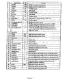
Figure 7 is an example of a list of signals for a connector that may connect to a smart cable according to one embodiment of the presentation. -
Figure 1 illustrates a simplified cable apparatus according to an exemplary embodiment of the present invention that is capable of communicating information such as cable identification and authentication upon connection to another device.Cable apparatus 100 may includeconnector 110 at one end, one or more connector ends 120 at another end, andcable 130 as well as one ormore cable lines 140 that couple the connector ends of the cable apparatus.Connector 110 may includecontact housing 112 which encloses a plurality of electrical contacts (not shown), andconnector boot 114 which houses the assembly that connects wires from the cable lines to the electrical contacts. Withinconnector boot 114, there can also be electronic components (not shown) that are configured to perform electrical functionality such as cable authentication, cable identification, electrostatic discharge protection and the like. One example of a connector assembly that can integrate such functionality onto, for example, a printed circuit board (PCB) inside the boot of the connector is described in the above-referencedpatent application number 11/650,330 - Plurality of
cable lines 140 may be configured to carry a respective plurality of signals, each line connecting to at least one of plurality ofconnectors 120. By way of example, plurality ofconnectors 120 may include at least an audio connector, a video connector, and/or a USB connector. Ifcable system 100 is configured to provide, for example, a composite video cable, the circuitry that may be integrated insideboot 114 ofconnector 110 can be configured to identify the type of cable and transmit that information (i.e., that the cable is a composite video cable) to the device to which it connects. The device could be, for example, a media device such as an iPod or an iPhone. The media device then automatically provides the appropriate signal, i.e., composite video signal, to the cable.Cable apparatus 100 can provide any one or more of the other types of cables and signals that media devices such as the iPod support, including analog audio, digital (USB) audio, component video, HDMI, DVI, S-video, etc. - Various modifications and variations to
cable apparatus 100 are possible. For example, eachline 140 may include one or more lines, each of which can independently carry one or more signals. In another example,cable lines 140 may include only one line that is combined withcable 130 to form a single cable. According to some embodiments, one or more additional components may be added to those noted above. Depending upon the embodiment, the specific arrangement of components may be interchanged. Further details of the various arrangements and cabling components can be found throughout the present specification below. -
Figure 2 illustrates a high level block diagram forconnector 110 incable apparatus 100 according to an exemplary embodiment of the present invention. As discussed above,connector 110 may include acontact housing 112 and aconnector boot 114. In one embodiment,connector boot 114 houses a PCB (not shown) on which various circuit components can be mounted. The circuit components can include, for example,micro-controller 210,authentication coprocessor 220, andidentification wire 230 that may be electrically coupled together via circuit traces on the PCB. An example of the internal construction ofconnector 100 can be found in the above-referencedpatent application number 11/650,330 connector 110, it is possible that parts or all of the components are distributed in other parts ofcable apparatus 100. Also, these components may be integrated into a single chip or a plurality of integrated circuits. - As shown in
Figure 2 ,micro-controller 210,authentication coprocessor 220 andidentification wire 230 are coupled together and in combination provide the additional functionality.Micro-controller 210 can be primarily responsible for controlling communication to and from the media device viabus 240.Authentication coprocessor 220 can be primarily responsible for implementing the authentication functionality. Andidentification wire 230 can be used bymicro-controller 210 to detect the type of signal the cable is configured to carry (e.g., component video or composite video). Abus 250 can connect the wires fromcable 130 to the contacts (or pins) incontact housing 112. There can be anoptional bus 260 directly connectingcable 130 tomicro-controller 210. As used herein the term bus refers to any mechanism that electrically connects one set of contact points to another and is not limited to any specific type of electro-mechanical means. - In operation, when
connector 110 is connected to a media device, the media device may send an authentication inquiry to the cable.Micro-controller 210 can receive the authentication inquiry and communicate it toauthentication coprocessor 220.Authentication coprocessor 220 then processes the authentication request using an authentication algorithm. The authentication algorithm can be based on, for example, public key encryption using security certificates, digital signatures or other known authentication methodologies. In one embodiment, authentication techniques similar to those described in commonly-assignedU.S. , (Attorney Docket No. 20750P-001110/P3503US1) titled "Accessory Authentication For Electronic Devices," can be implemented byPatent Application Number 11/051,499authentication coprocessor 220. The result of the authentication process is communicated fromauthentication coprocessor 220 tomicro-controller 210 and frommicro-controller 210 to the media device viabus 240. Upon successful authentication, the media device may proceed with further communication with the cable apparatus. While the block diagram ofFigure 2 showsmicro-controller 210 andauthentication coprocessor 220 as two separate components, it is possible to integrate both functionalities into a single chip. - Another functionality integrated in and provided by the cable apparatus according to an embodiment of the present invention is cable identification. According to this embodiment, a signal such as a voltage level provided on
identification wire 230 indicates a type of cable. The signal onidentification wire 230 can, for example, indicate whether the cable is configured to carry, e.g., composite video, component video or S-video signal. The level of the signal onidentification wire 230 can be set by, for example, a resistive circuit that may be coupled either to the power supply (i.e., as a pull-up) or to ground (i.e., as a pull-down) or between both to form a voltage divider. It is also possible to not connectidentification wire 230 to any signal and instead use a floating condition to also indicate a type of cable. This embodiment envisions that the cable manufacturer sets the signal level onidentification wire 230 simplifying the implementation ofmicro-controller 210. This allows the use of a more cost-effective micro-controller 210 that can be programmed to detect the signal level onidentification wire 230. In this embodiment, oncemicro-controller 210 determines the type of cable it is associated with, it may internally save that information in a register so that it does not have to make that determination each time it is connected to a media device. Once the cable type is identified (and in some embodiments after the cable is authenticated),micro-controller 210 can transmit a request signal to a media device to which it is connected to enable the appropriate (e.g., audio and/or video) outputs in the correct format. While in this example, the type of cable is determined based on voltage level onidentification wire 230, it is also possible to accomplish similar functionality with techniques other than voltage level detection, such as current sensing. - In an alternative embodiment, a more
sophisticated micro-controller 210 can eliminate the need foridentification wire 230 and its associated circuitry by dynamically detecting the type of cable being used. According to this embodiment,micro-controller 210 can be programmed to detect the type of cable upon connection between the media device and an accessory device.Figure 3 depictscable apparatus 100 connecting amedia device 310 to one or moreaccessory devices 320.Connector end 110 ofcable apparatus 100 connects tomedia device 310 viacontacts 112 while any one or more of connector ends 120 connect to one or moreaccessory devices 320. - According to this embodiment,
micro-controller 210 can test whether a connection is made at the accessory end via any one or more ofcables 140. This can be done, for example, bymicro-controller 210 applying one or more test signals to pre-determined contact pins 112 that are designated to carry specific signal types when connected bycable apparatus 100 to one or moreaccessory devices 320. In an alternative embodiment,micro-controller 210 can apply the test signals directly to pre-determined wires incable 130 via bus 260 (seeFigure 2 ). Based on the signal(s) returned tomicro-controller 210 in response to the test signal(s), the micro-controller can determine how many and which connector end(s) 120 are in fact connected to an accessory. This will enable micro-controller 210 to identify the type of cable being used. For example, if only oneconnector end 120, such as a male RCA plug for a single composite video cable, is connected,micro-controller 210 will identify the cable as a composite video cable. If, on the other hand, the test indicates connection of three connector ends 120 corresponding to component video signal, then micro-controller 210 identifies the cable as component video cable. It is also possible formicro-controller 210 to determine an erroneous connection (e.g., when only one of the three component connector ends is connected) andsignal media device 310 to indicate the erroneous connection on its display. Accordingly, in this embodiment, the cable type is determined by the connection it is providing and therefore can vary from one application to the next. That is, in one application wherein the cable connects a media device to, for example, a video accessory that uses composite video signals,micro-controller 210 will identify the cable type as composite video cable. The same cable when used in another application for connecting a media device to, for example, a video accessory that uses component video will be identified bymicro-controller 210 as a component video. - Once the type of cable is determined (and, in some embodiments, after the cable is authenticated),
micro-controller 210 can transmit the cable preferences for that particular cable type to the media device. The cable preferences depend on the cable type which can be any one or more of the following: USB, Firewire, analog or digital audio, composite video, component video, S-video, HDMI, DVI and the like. For example, preferences for a composite video cable can be audio line out and composite video. - In one application,
cable apparatus 100 may be used to connect a media device such as an iPod to both a television set via video connector ends and a hi-fi speaker system via the audio connector ends.Cable apparatus 100 automatically performs the authentication process upon connection tomedia device 310.Cable apparatus 100 can also perform the cable identification process upon connection tomedia device 310 or upon connection to bothmedia device 310 andaccessory devices 320.Micro-controller 210 can perform the cable identification task before, after or in parallel with the authentication process. -
Figures 4 ,5 and6 illustrate various simplified methods of operation for the smart cable according to embodiments of the present invention.Method 400 shown inFigure 4 depicts one authentication method which may includeprocess 410 for powering up the cable circuitry upon connection to an electronic device such as a media player or an accessory. Once powered up, the cable circuitry may receive an authentication inquiry from the media device (process 420). It is also possible that the authentication inquiry sent from the media device to the cable circuitry may be prompted by the cable circuitry itself requesting to be authenticated. In response to the authentication inquiry, the cable circuitry may process the authentication inquiry and generate an authentication response (process 430). The cable circuitry may next send the authentication response back to the media device (process 440). If the authentication response is accepted by the media device (process 450), cable preferences may be transmitted to the media device (process 460) and further communication via the cable apparatus may be authorized (process 470). If the authentication process fails, the cable may be assumed to be unauthorized and no further communication via that cable may be allowed. In one embodiment, the authorization process may be retried one or more times before the cable apparatus is rejected (process 480). - As discussed in connection with
Figures 2 and3 , these various processes are performed, in one exemplary implementation, by the combination ofmicro-controller 210 andauthentication coprocessor 220. That is, atprocess 410 upon connecting the cable tomedia device 320, the internal circuitry of thecable including micro-controller 210 andauthentication coprocessor 220 may be powered using, for example, power supplied from media device 320 (or an accessory when connected to an accessory). After power-up, atprocess 420,micro-controller 210 may receive an authentication request frommedia device 320. Atprocess 430,micro-controller 210 then communicates withauthentication coprocessor 220 to process the request in accordance with the authentication algorithm implemented bycoprocessor 220. Atprocess 440, the response generated byauthentication coprocessor 220 is then sent back tomedia device 310 viamicro-controller 210. Accordingly, this method provides for a smart cable that includes all the resources to automatically go through an authentication process upon connection to a media device. -
Figure 5 is a flowdiagram depicting method 500 of cable identification according to another embodiment of the present invention.Method 500 may includeprocess 510 for powering up the cable circuitry upon connection to an electronic device such as a media player or an accessory,process 520 for identifying the type of cable,process 530 for generating a cable identification signal, andprocess 540 for sending the cable identification signal to the media device. As discussed in connection withFigures 2 and3 , these various processes are performed, in one exemplary implementation, bymicro-controller 210. That is,process 510 may include powering the internal circuitry of thecable including micro-controller 210 andauthentication coprocessor 220 upon connecting the cable to media device 320 (or to an accessory) using, for example, power supplied frommedia device 320. After power-up,process 520 may include micro-controller 210 identifying the cable type. The identification of cable type byprocess 530 may involve micro-controller 210 detecting a signal level onidentification wire 230. Alternatively,micro-controller 210 can detect the cable type by the configuration in which the cable is being used and the type ofaccessory 320 to which it is connected. Next,process 530 may include micro-controller 210 generating an identification signal and then,process 540 may include sending the identification signal tomedia device 310. The identification signal may include cable preferences. In response,media device 310 may use the identification signal and automatically start transmitting audio and/or video signals to thecable apparatus 100 according to preferred or required signal formats. - Alternatively,
media device 310 may use the identification signal and narrow its displayed menu choices (e.g., showing only the video files that are available in component format). In one example, the identification signal may instruct the media device to transmit audio signals but no video signals to the cable apparatus, and/or may also specify the type of audio signals that is preferred or required by the cable apparatus. In another example, the identification signal may instruct the media device to transmit both audio signals and video signals to the cable apparatus. Additionally, the identification signal may also specify the preferred or required type of audio signals, and/or specify the preferred or required type of video signals. For example, the type of video signal may be composite, component, digital audio, S-video, HDMI, etc. In one embodiment, the type of video signals that is preferred or required by the cable apparatus may be component video signals (e.g., Y, Pb, Pr signals). Accordingly, this method provides for a smart cable that includes all the resources to automatically identify the cable type and send cable preferences to the media device upon connection to the media device. -
Figure 6 is a flowdiagram depicting method 600 of cable identification and authentication according to another embodiment of the present invention.Method 600 essentially combinesmethods Figure 6 ,method 600 may includeprocess 610 for powering up the cable circuitry upon connection to a media device (or an accessory). The method may also includeprocess 620 involving the cable circuitry identifying a cable type, andprocess 630 for the cable circuitry generating and transmitting a cable identification signal to the media device. - Next, in response to a request from the media device to initiate the authentication process,
method 600 may also includeprocess 640 whereby the cable circuitry starts the authentication algorithm and generates an authentication response.Process 640 is followed byprocess 650 which may include sending the authentication response back to the media device. If the cable authentication is successful (process 660), the cable then may send its preferences to the media device (process 670) after which media content may be communicated over the cable (process 680). The cable preferences may include, for example, enabling audio and/or video line out, etc. If authentication fails,method 600 may includeprocess 690 whereby the authentication processes (640 and 650) are repeated a predetermined number of times (n) before rejecting the cable as unauthorized. The details of operation of the authentication process and the cable identification process have been described above in connection withFigures 4 and5 and will not be repeated. It is emphasized here, however, that each of the process flow diagrams depicts an exemplary embodiment and modifications and alternatives are possible. For example, the identification process and or the authentication process may occur with or without an inquiry from the media device. For example, in one embodiment, the process (630) whereby the cable identifies its type to the media device may include the cable also requesting to be authenticated. In response to this request from the cable, the media device may send an authentication request signal to the cable initiating the cable authentication process. Also, thevarious authentication processes identification processes - In one embodiment, the authentication processes 640 and 650 may occur first and, depending on the result of the authentication challenge, the remaining processes may proceed or may be halted. According to this embodiment, if the cable apparatus transmits the expected authentication response,
media device 310 may confirm that the coupled cable apparatus is an authorized cable allowing further processes including the cable identification process to continue. If, however, no authentication response is received or if incorrect authentication response is received, the media device may be prevented from transmitting data through the attached cable apparatus, and subsequent processes cannot proceed. - In all of the various embodiments described above, communication between the cable apparatus, the media device and the accessory can be based on any one of a variety of interface protocols. One example of such an interface protocol is the iPod Accessory Protocol developed by Apple Inc. that can facilitate communication between an iPod or iPhone and accessories via a smart cable apparatus according to the present invention. This particular protocol is described in greater detail in commonly assigned
U.S. Patent Number 7,293,122 , entitled "Connector Interface System Facilitating Communication Between a Media Player and an Accessory," to Schubert et al. Also, one example of the type of connector suitable forconnector 110 over which the above-referenced interface protocol can be communicated is described in the above-referencedpatent application number 11/650,330 Figure 7 , a specific number of pins (e.g., 30) and signal assignments for those pins that facilitate the protocol. - An exemplary embodiment of the present invention provides a cable apparatus comprising: a first connector including a housing, a plurality of contacts, and one or more processing components, the plurality of contacts being configured to couple to a first electronic device; a cable coupled to the first connector; and one or more second connectors coupled to the cable and configured to couple to one or more second electronic devices; wherein the one or more processing components are configured to identify a type of the cable apparatus, generate an identification signal, and send the identification signal to the first electronic device through the plurality of contacts, wherein the identification signal identifies what types of signals the cable apparatus can carry.
- According to another exemplary embodiment of the present invention for the cable apparatus, the one or more processing components include a micro-controller coupled to an identification circuit.
- According to another exemplary embodiment of the present invention for the cable apparatus above the micro-controller is further configured to detect a signal level supplied by the identification circuit and to determine the type of the cable apparatus based at least on the detected signal level.
- According to another exemplary embodiment of the present invention for the cable apparatus above, the signal level supplied by the identification circuit is predetermined.
- According to another exemplary embodiment of the present invention for the cable apparatus, the one or more processing components include a micro-controller that is configured to determine the type of the cable apparatus based on detecting which of the one or more second connectors are connected to respective one or more second electronic devices.
- According to another exemplary embodiment of the present invention for the cable apparatus, the types of signals the cable apparatus can carry can be one or more from among a plurality of signal types including composite video, component video, S-video, HDMI or other digital video formats.
- According to another exemplary embodiment of the present invention for the cable apparatus, the one or more processing components are further configured to receive an authentication inquiry from a the first electronic device through the plurality of contacts, to generate an authentication response, and to send the authentication response to the first electronic device through the plurality of contacts.
- Another exemplary embodiment of the present invention provides a method for identifying a cable apparatus, the method comprising: the cable apparatus detecting a signal level on an identification wire inside the cable apparatus; the cable apparatus identifying a cable type based on the detected signal level on the identification wire; and the cable apparatus sending to an electronic device, a cable identification signal based at least in part on information associated with the identified cable type, wherein, the identification signal is associated with one or more types of signals related to the cable apparatus.
- According to another exemplary embodiment of the present invention for the method, the identification wire is coupled to a resistor.
- According to another exemplary embodiment of the present invention for the method, the identification wire is coupled to a resistor divider.
- According to another exemplary embodiment of the present invention for the method, it further comprises the cable apparatus receiving an identification request from the electronic device.
- Another exemplary embodiment of the present invention provides a method of identifying types of electronic device coupled to a cable apparatus, the method comprising: the cable apparatus detecting a type of first electronic device to which it is connected through a first connector by applying one or more test signals to one or more pins of the first connector; the cable apparatus identifying a cable type based on one or more signals returned in response to the one or more test signals applied to the first connector; and the cable apparatus sending to a second electronic device, a cable identification signal based at least in part on information associated with the identified cable type.
- According to another exemplary embodiment of the present invention for the method, it further comprises: the cable apparatus detecting a type of second electronic device to which it is connected through a second connector by applying one or more test signals to one or more pins of the second connector; the cable apparatus identifying a cable type based on one or more signals returned in response to the one or more test signals applied to the second connector.
- According to another exemplary embodiment of the present invention for the method, it further comprises the cable apparatus receiving an identification request from the second electronic device.
- Another exemplary embodiment of the present invention provides a method of operating a cable apparatus, the method comprising: an identification method comprising: receiving power from an electronic device; and without receiving a request for a cable identification signal from the electronic device, sending to the electronic device a cable identification signal based at least in part on information associated with an identified cable type; wherein the identification signal is associated with one or more types of signals related to the cable apparatus; and an authentication method comprising: the cable apparatus receiving an authentication inquiry from an electronic device; the cable apparatus processing the authentication inquiry by an authentication circuitry; the authentication circuitry generating an authentication response that is associated with whether the cable apparatus is an authorized accessory for the electronic device; and the cable apparatus sending the authentication response from the cable apparatus to the electronic device.
- According to another exemplary embodiment of the present invention for the method, the identification method further comprises: the cable apparatus detecting a signal level on an identification wire inside the cable apparatus; and the cable apparatus identifying a cable type based on the detected signal level on the identification wire.
- Multiple aspects of the present invention have been described in the context of specific embodiments for illustrative purposes only. Those skilled in the art will appreciate that various alternatives, modifications or changes are possible. The above description should therefore not be limiting of the scope of the present invention, which should instead be determined by the following claims and their full breadth of equivalents.
Claims (15)
- A cable apparatus (100) comprising:a first connector (110) including a housing (112), a plurality of contacts, and one or more processing components (114), the plurality of contacts being configured to couple to a first electronic device (310);a cable (130) coupled to the first connector (110); andone or more second connectors (120) coupled to the cable (130) and configured to couple to one or more second electronic devices (320);wherein the one or more processing components (114) comprise a micro-controller (210) and an authentication coprocessor (220),where the micro-controller (210) is configured to:receive a first authentication inquiry from the first electronic device through the plurality of contacts, andprovide the first authentication inquiry to the authentication coprocessor, andwherein the coprocessor (220) is configured to:process the first authentication inquiry using an authentication algorithm,generate a first authentication response based on the result of processing the first authentication inquiry using the authentication algorithm, andsend the first authentication response to the micro-controller (210),where the micro-controller (210) is further configured to provide the first authentication response to the first electronic device (310) through the plurality of contacts.
- The cable apparatus (100) of claim 1 wherein the micro-controller (210) detects a signal level on an identification wire (230) inside the cable apparatus (100) and identifies a cable type based on the detected signal level on the identification wire.
- The cable apparatus (100) of claim 2 wherein the identification wire is coupled to a resistor and is not connected to the plurality of contacts, wherein the signal level is a voltage level, and wherein the identification wire is set to have the voltage level.
- The cable apparatus (100) of claim 2 wherein the identification wire is coupled to a resistor divider, wherein the signal level is a voltage level between two resistors of the resistor divider.
- The cable apparatus (100) of claim 1 wherein the authentication processor processes the first authentication inquiry using either or both digital signatures and security certificates.
- The cable apparatus (100) of claim 1 wherein the authentication processor processes the first authentication inquiry using public key encryption.
- The cable apparatus (100) of claim 1 wherein after the first authentication response is sent to the first electronic device, the first electronic device continues to communicate with the cable apparatus.
- The cable apparatus (100) of claim 1 wherein the one or more processing components (114) are housed inside a boot of the first connector and electrically couple to one or more of the plurality of contacts.
- A method of operating a cable apparatus as defined by claim 1, the method comprising an authentication method comprising:the cable apparatus (100) receiving a first authentication inquiry from an electronic device with a micro-controller (210), the cable apparatus (100) receiving the first authentication inquiry upon being coupled to the electronic device for the first time;the micro-controller (210) providing the first authentication inquiry to an authentication coprocessor (220), the authentication coprocessor (220) processing the first authentication inquiry;
in response to the first authentication inquiry, the authentication coprocessor generating a first authentication response that is associated with whether the cable apparatus (100) is an authorized accessory for the electronic device (310) and providing the first authentication response to the micro-controller (210); andthe micro-controller (210) sending the first authentication response from the cable apparatus (100) to the electronic device, the first authentication response allowing the cable apparatus (100) to provide communication with the electronic device if the first authentication response is accepted by the electronic device. - The method of claim 9 wherein the authentication processor processes the first authentication inquiry using either or both digital signatures and security certificates.
- The method of claim 9 wherein the authentication processor processes the first authentication inquiry using public key encryption.
- The method of claim 9 further comprising a cable identification method, the cable identification method comprising:the micro-controller (210) detecting a signal level on an identification wire (230) inside the cable apparatus (100);the micro-controller (210) identifying a cable type based on the detected signal level on the identification wire; andthe micro-controller (210) sending to the electronic device, a cable identification signal based at least in part on information associated with the identified cable type,wherein, the identification signal is associated with one or more types of signals related to the cable apparatus (100).
- The method of claim 12 wherein the identification wire is coupled to a resistor.
- The method of claim 12 wherein the identification wire is coupled to a resistor divider.
- The method of claim 12 wherein the cable identification method further comprises the cable apparatus (100) receiving an identification request from the electronic device.
Applications Claiming Priority (2)
| Application Number | Priority Date | Filing Date | Title |
|---|---|---|---|
| US96994607P | 2007-09-04 | 2007-09-04 | |
| US12/030,429 US8095713B2 (en) | 2007-09-04 | 2008-02-13 | Smart cables |
Publications (3)
| Publication Number | Publication Date |
|---|---|
| EP2034423A2 EP2034423A2 (en) | 2009-03-11 |
| EP2034423A3 EP2034423A3 (en) | 2009-03-25 |
| EP2034423B1 true EP2034423B1 (en) | 2015-12-02 |
Family
ID=39865916
Family Applications (1)
| Application Number | Title | Priority Date | Filing Date |
|---|---|---|---|
| EP08015543.5A Active EP2034423B1 (en) | 2007-09-04 | 2008-09-03 | Smart cables |
Country Status (10)
| Country | Link |
|---|---|
| US (1) | US8095713B2 (en) |
| EP (1) | EP2034423B1 (en) |
| JP (2) | JP4612110B2 (en) |
| CN (1) | CN201515041U (en) |
| AU (2) | AU2008296401B2 (en) |
| FR (1) | FR2996068B1 (en) |
| GB (2) | GB2452605B (en) |
| HK (2) | HK1130542A1 (en) |
| TW (1) | TWI392172B (en) |
| WO (1) | WO2009032797A2 (en) |
Families Citing this family (85)
| Publication number | Priority date | Publication date | Assignee | Title |
|---|---|---|---|---|
| US6850788B2 (en) | 2002-03-25 | 2005-02-01 | Masimo Corporation | Physiological measurement communications adapter |
| US7589536B2 (en) | 2007-01-05 | 2009-09-15 | Apple Inc. | Systems and methods for determining the configuration of electronic connections |
| US8840549B2 (en) | 2006-09-22 | 2014-09-23 | Masimo Corporation | Modular patient monitor |
| US7625239B1 (en) * | 2007-11-30 | 2009-12-01 | Nvidia Corporation | Single-to-multiple display adapter utilizing a single cable construction |
| KR101516637B1 (en) * | 2007-12-24 | 2015-05-06 | 엘지전자 주식회사 | Computer with networking module and Method for transmitting data using the same |
| EP2192573B1 (en) * | 2008-11-26 | 2020-12-30 | Samsung Electronics Co., Ltd. | Display apparatus using external device connection unit and method of determining format of input image thereof |
| EP2410716B1 (en) | 2009-02-13 | 2020-04-08 | CommScope Technologies LLC | Device for use with physical layer information |
| US20100253363A1 (en) * | 2009-04-03 | 2010-10-07 | Mindspeed Technologies, Inc. | Method and system for cable detection |
| US8370959B2 (en) * | 2009-07-23 | 2013-02-05 | Cisco Technology, Inc. | Connection device authentication |
| US9153112B1 (en) | 2009-12-21 | 2015-10-06 | Masimo Corporation | Modular patient monitor |
| US8886849B2 (en) | 2012-05-11 | 2014-11-11 | Apple Inc. | Multi-mode adapter |
| DE102010021257A1 (en) | 2010-05-21 | 2011-11-24 | Siemens Aktiengesellschaft | Plug-in system for the protected construction of a network connection |
| KR101521691B1 (en) | 2010-05-28 | 2015-05-19 | 애플 인크. | Plug connector, conductive frame for electrical connector, and electronic device |
| JP2012028302A (en) | 2010-06-25 | 2012-02-09 | Sony Corp | Dye-sensitized solar cell and method for manufacturing the same |
| US8412857B2 (en) | 2010-11-22 | 2013-04-02 | Motorola Mobility Llc | Authenticating, tracking, and using a peripheral |
| US8667303B2 (en) | 2010-11-22 | 2014-03-04 | Motorola Mobility Llc | Peripheral authentication |
| US8489784B2 (en) * | 2010-12-31 | 2013-07-16 | Silicon Image, Inc. | Adaptive interconnection scheme for multimedia devices |
| CN103329365B (en) | 2011-01-26 | 2016-01-06 | 苹果公司 | There are 180 degree and connect connector accessory freely |
| US8414337B2 (en) | 2011-05-20 | 2013-04-09 | Apple Inc. | Low profile male connector |
| KR101183326B1 (en) | 2011-05-20 | 2012-09-14 | 이백무 | Signal transmission cable |
| CN102984640A (en) * | 2011-09-05 | 2013-03-20 | 鸿富锦精密工业(深圳)有限公司 | Audio test cable |
| US9224359B2 (en) | 2011-09-26 | 2015-12-29 | Google Technology Holdings LLC | In-band peripheral authentication |
| EP2766834B1 (en) | 2011-10-13 | 2022-04-20 | Masimo Corporation | Medical monitoring hub |
| US9943269B2 (en) | 2011-10-13 | 2018-04-17 | Masimo Corporation | System for displaying medical monitoring data |
| US8708745B2 (en) | 2011-11-07 | 2014-04-29 | Apple Inc. | Dual orientation electronic connector |
| AU2015230752B2 (en) * | 2011-11-07 | 2016-09-29 | Apple Inc. | Techniques for configuring contacts of a connector |
| US9293876B2 (en) | 2011-11-07 | 2016-03-22 | Apple Inc. | Techniques for configuring contacts of a connector |
| US8762605B2 (en) * | 2011-11-30 | 2014-06-24 | Apple Inc. | Adapter for electronic devices |
| US8971072B2 (en) | 2011-12-30 | 2015-03-03 | Bedrock Automation Platforms Inc. | Electromagnetic connector for an industrial control system |
| US10834820B2 (en) * | 2013-08-06 | 2020-11-10 | Bedrock Automation Platforms Inc. | Industrial control system cable |
| US11314854B2 (en) | 2011-12-30 | 2022-04-26 | Bedrock Automation Platforms Inc. | Image capture devices for a secure industrial control system |
| US11144630B2 (en) | 2011-12-30 | 2021-10-12 | Bedrock Automation Platforms Inc. | Image capture devices for a secure industrial control system |
| US9191203B2 (en) | 2013-08-06 | 2015-11-17 | Bedrock Automation Platforms Inc. | Secure industrial control system |
| US9600434B1 (en) | 2011-12-30 | 2017-03-21 | Bedrock Automation Platforms, Inc. | Switch fabric having a serial communications interface and a parallel communications interface |
| US9727511B2 (en) | 2011-12-30 | 2017-08-08 | Bedrock Automation Platforms Inc. | Input/output module with multi-channel switching capability |
| US9467297B2 (en) | 2013-08-06 | 2016-10-11 | Bedrock Automation Platforms Inc. | Industrial control system redundant communications/control modules authentication |
| US10834094B2 (en) | 2013-08-06 | 2020-11-10 | Bedrock Automation Platforms Inc. | Operator action authentication in an industrial control system |
| US9437967B2 (en) | 2011-12-30 | 2016-09-06 | Bedrock Automation Platforms, Inc. | Electromagnetic connector for an industrial control system |
| US8868813B2 (en) | 2011-12-30 | 2014-10-21 | Bedrock Automation Platforms Inc. | Communications control system with a serial communications interface and a parallel communications interface |
| US10149616B2 (en) | 2012-02-09 | 2018-12-11 | Masimo Corporation | Wireless patient monitoring device |
| US9652194B2 (en) * | 2012-02-29 | 2017-05-16 | Apple Inc. | Cable with video processing capability |
| JP5641009B2 (en) * | 2012-04-13 | 2014-12-17 | 日本電気株式会社 | Connector, relay cable and information processing apparatus |
| US8683090B2 (en) * | 2012-04-19 | 2014-03-25 | Apple Inc. | Methods, systems and apparatus for determining whether an accessory includes particular circuitry |
| US9167393B2 (en) | 2012-05-02 | 2015-10-20 | Nextlink Ipr Ab | Cable chip system |
| WO2013184776A1 (en) * | 2012-06-08 | 2013-12-12 | 3M Innovative Properties Company | Modular communication device and system |
| US8690595B2 (en) | 2012-06-25 | 2014-04-08 | Cooper Technologies Company | Squid connector with coupling feature |
| US9459670B2 (en) | 2012-09-07 | 2016-10-04 | Apple Inc. | Adapter for use with a portable electronic device |
| US9021159B2 (en) | 2012-09-07 | 2015-04-28 | Apple Inc. | Connector adapter |
| US9749232B2 (en) | 2012-09-20 | 2017-08-29 | Masimo Corporation | Intelligent medical network edge router |
| DE112012007169T5 (en) * | 2012-12-21 | 2015-08-06 | Hewlett-Packard Development Company, L.P. | Cable embedded active component |
| US11797469B2 (en) | 2013-05-07 | 2023-10-24 | Snap-On Incorporated | Method and system of using USB user interface in electronic torque wrench |
| KR102048222B1 (en) | 2013-05-21 | 2019-11-25 | 삼성전자주식회사 | Apparatus and method for recognizing an external device in a communication system |
| US10613567B2 (en) | 2013-08-06 | 2020-04-07 | Bedrock Automation Platforms Inc. | Secure power supply for an industrial control system |
| US9547289B2 (en) * | 2013-09-16 | 2017-01-17 | Ledgestone Holdings, LLC | Field-configurable user interface circuit and method of installation |
| US10832818B2 (en) | 2013-10-11 | 2020-11-10 | Masimo Corporation | Alarm notification system |
| US9357654B2 (en) | 2014-03-03 | 2016-05-31 | Apple Inc. | Low-profile plug with cam and flexible circuit board |
| GB2524973A (en) * | 2014-04-07 | 2015-10-14 | Intelligent Energy Ltd | Power supply apparatus |
| AU2015248452A1 (en) * | 2014-04-18 | 2016-11-24 | Healthwatch Ltd. | Connector and cable assembly for smart garments |
| WO2015187624A1 (en) * | 2014-06-03 | 2015-12-10 | QFusion Labs, LLC | Smart connector for electronic components |
| CN111293495B (en) * | 2014-07-07 | 2022-05-24 | 基岩自动化平台公司 | Industrial control system cable |
| KR101586149B1 (en) * | 2014-07-22 | 2016-01-20 | 동의대학교 산학협력단 | Data cable apparatus and system including the same |
| FR3039716B1 (en) * | 2015-07-27 | 2017-08-25 | Sylumis | IMPROVED DEVICE AND METHOD FOR CONNECTING A FIRST BEAM OF CONNECTED CONDUCTORS FREELY TO A BEAM OF IDENTIFIED CONDUCTORS |
| JP6550296B2 (en) * | 2015-08-07 | 2019-07-24 | ルネサスエレクトロニクス株式会社 | Power supply system |
| JP2017039369A (en) * | 2015-08-19 | 2017-02-23 | 株式会社オートネットワーク技術研究所 | On-vehicle connector pair |
| JP6840473B2 (en) | 2016-06-24 | 2021-03-10 | 株式会社東芝 | Adapter device |
| US10617302B2 (en) | 2016-07-07 | 2020-04-14 | Masimo Corporation | Wearable pulse oximeter and respiration monitor |
| KR20180024881A (en) * | 2016-08-31 | 2018-03-08 | 삼성전자주식회사 | Content providing device and power source controlling method thereof |
| CN107819636A (en) * | 2016-09-13 | 2018-03-20 | 联想企业解决方案(新加坡)有限公司 | Apparatus and method for locating data cable |
| JP6752675B2 (en) * | 2016-10-12 | 2020-09-09 | ルネサスエレクトロニクス株式会社 | Semiconductor devices, control methods for semiconductor devices, and semiconductor systems |
| US10615554B2 (en) | 2016-10-26 | 2020-04-07 | Tri-Lock Technologies Llc | Multi-functional cord apparatus and system |
| JP6776817B2 (en) * | 2016-10-31 | 2020-10-28 | 住友電気工業株式会社 | How to change the connection device and the operation contents of the connection device |
| DE102016222617A1 (en) * | 2016-11-17 | 2018-05-17 | Siemens Aktiengesellschaft | Protective device and network cabling device for protected transmission of data |
| EP3583433A4 (en) * | 2017-02-14 | 2020-08-05 | Ideal Industries Networks Limited | System and method for using a connector at the end of a cable as a cable locating tone sensor |
| CN110709770B (en) * | 2017-05-31 | 2021-09-14 | 佳能株式会社 | Camera, accessory device, communication control method, storage medium, and camera system |
| JP2019046066A (en) * | 2017-08-31 | 2019-03-22 | 株式会社東芝 | Electronic device and cable |
| JP7107669B2 (en) * | 2017-12-04 | 2022-07-27 | 矢崎総業株式会社 | In-vehicle control system and wire harness |
| EP3782165A1 (en) | 2018-04-19 | 2021-02-24 | Masimo Corporation | Mobile patient alarm display |
| US20200221933A1 (en) * | 2019-01-13 | 2020-07-16 | Stryker Corporation | Systems and methods for connecting a medical imaging device to a medical imaging controller |
| JP6645669B1 (en) * | 2019-01-21 | 2020-02-14 | Necプラットフォームズ株式会社 | Interface circuit, information processing device, display method, and program |
| CA3107827A1 (en) * | 2020-02-07 | 2021-08-07 | Bikef S.R.L. | Charging system and method of a battery of an electric vehicle |
| WO2021202213A2 (en) * | 2020-03-30 | 2021-10-07 | Zoll Medical Corporation | Medical device system and hardware for sensor data acquisition |
| CN115864582A (en) * | 2020-07-15 | 2023-03-28 | 华为技术有限公司 | Data transmission method based on charging cable and electronic equipment |
| JP2022030808A (en) * | 2020-08-07 | 2022-02-18 | キヤノン株式会社 | Power reception device, control method thereof, and program |
| TWI783293B (en) * | 2020-11-09 | 2022-11-11 | 瑞昱半導體股份有限公司 | Method for identifying signal transmission device and signal processing system |
| US20220166762A1 (en) * | 2020-11-25 | 2022-05-26 | Microsoft Technology Licensing, Llc | Integrated circuit for obtaining enhanced privileges for a network-based resource and performing actions in accordance therewith |
Citations (2)
| Publication number | Priority date | Publication date | Assignee | Title |
|---|---|---|---|---|
| US20050182876A1 (en) * | 2004-02-18 | 2005-08-18 | Silicon Image, Inc. | Cable with circuitry for asserting stored cable data or other information to an external device or user |
| WO2008118616A1 (en) * | 2007-03-23 | 2008-10-02 | Universal Electronics Inc. | System and method for upgrading the functionality of a controlling device in a secure manner |
Family Cites Families (111)
| Publication number | Priority date | Publication date | Assignee | Title |
|---|---|---|---|---|
| US2007117A (en) * | 1932-05-27 | 1935-07-02 | Standard Oil Dev Co | Sectional fractionating column |
| US4850899A (en) * | 1988-06-20 | 1989-07-25 | Maynard Scott D | Connector for interfacing a disk drive with a computer |
| NL8902192A (en) * | 1989-08-30 | 1991-03-18 | Du Pont Nederland | BUILT-IN CONNECTOR WITH A LOCKING FRAME. |
| US5108313A (en) * | 1989-10-05 | 1992-04-28 | E. I. Du Pont De Nemours And Company | Modular connector |
| US5041025A (en) | 1990-01-31 | 1991-08-20 | Thomas & Betts Corporation | Interconnectable components employing a multi-positionable key |
| NL9000967A (en) * | 1990-04-23 | 1991-11-18 | Du Pont Nederland | DEVICE FOR ELECTRO-OPTICAL SIGNAL CONVERSION. |
| US5055069A (en) * | 1990-06-08 | 1991-10-08 | E. I. Du Pont De Nemours And Company | Connectors with ground structure |
| FR2685556B1 (en) * | 1991-12-23 | 1994-03-25 | Souriau & Cie | MODULAR ELEMENT FOR ELECTRICAL CONNECTION. |
| US5186646A (en) * | 1992-01-16 | 1993-02-16 | Pederson William A | Connector device for computers |
| US6054846A (en) * | 1994-02-18 | 2000-04-25 | Ergo Mechanical Systems, Incorporated | Universal power-supply connection system for multiple electronic devices, and devices for use therewith |
| DE69421798T2 (en) | 1994-03-26 | 2004-07-15 | Molex Inc., Lisle | Modular Jack connector |
| US5830001A (en) * | 1995-03-31 | 1998-11-03 | Japan Aviation Electronics Industry, Limited | Connector capable of reliably locking a plug connector to a receptacle connector |
| JP2757139B2 (en) * | 1995-04-04 | 1998-05-25 | 日本航空電子工業株式会社 | Shielded connector |
| US5664229A (en) * | 1995-05-18 | 1997-09-02 | Symbol Technologies, Inc. | Accessory for conversion with housing with first connection includes host cable and host connector and second connection including a plug-in modular connector |
| US5586893A (en) * | 1995-07-17 | 1996-12-24 | Itt Corporation | IC card connector shield grounding |
| US5698817A (en) * | 1995-10-11 | 1997-12-16 | The United States Of America As Represented By The Secretary Of The Navy | Unmanned undersea weapon deployment structure with cylindrical payload deployment system |
| US5873000A (en) * | 1996-07-19 | 1999-02-16 | Compaq Computer Corporation | System incorporating hot docking and undocking capabilities without requiring a standby or suspend mode by placing local arbiters of system and base into idle state |
| EP0845750A3 (en) * | 1996-11-29 | 2000-11-29 | Tyco Electronics Logistics AG | Double connector for two chip cards |
| US6206480B1 (en) * | 1997-03-25 | 2001-03-27 | Eric Thompson | Mobile computing and communication system |
| JPH10289760A (en) * | 1997-04-11 | 1998-10-27 | Molex Inc | Metal shell connection means |
| US6564009B2 (en) * | 1997-05-19 | 2003-05-13 | Sony Corporation | Apparatus for recording and/or reproducing data onto and/or from an optical disk and method thereof |
| JP2924857B2 (en) | 1997-05-23 | 1999-07-26 | ミツミ電機株式会社 | Electrical connector |
| JPH10334993A (en) | 1997-05-29 | 1998-12-18 | Japan Aviation Electron Ind Ltd | Connector device |
| TW376211U (en) * | 1997-08-26 | 1999-12-01 | Hon Hai Prec Ind Co Ltd | Receptacles of the power connector |
| JPH11111405A (en) * | 1997-10-03 | 1999-04-23 | Japan Aviation Electron Ind Ltd | Connector for mounting on substrate |
| US6131125A (en) * | 1997-11-14 | 2000-10-10 | Kawasaki Lsi U.S.A., Inc. | Plug-and-play data cable with protocol translation |
| US6370603B1 (en) * | 1997-12-31 | 2002-04-09 | Kawasaki Microelectronics, Inc. | Configurable universal serial bus (USB) controller implemented on a single integrated circuit (IC) chip with media access control (MAC) |
| KR100524056B1 (en) * | 1998-03-09 | 2006-03-09 | 삼성전자주식회사 | 2-way speaker system |
| JP2005136980A (en) | 1998-05-19 | 2005-05-26 | Sega Corp | Information processor and connection cable used therefor |
| US6654840B1 (en) * | 1998-05-19 | 2003-11-25 | Sega Enterprises, Ltd. | Connection cable identification mechanism |
| US6116943A (en) * | 1998-06-30 | 2000-09-12 | The Whitaker Corporation | Modular plug having a circuit board |
| JP2000223218A (en) | 1999-01-27 | 2000-08-11 | Mitsumi Electric Co Ltd | Small-sized connector |
| JP2000223216A (en) | 1999-01-27 | 2000-08-11 | Mitsumi Electric Co Ltd | Small-sized connector |
| JP2000223215A (en) | 1999-01-27 | 2000-08-11 | Mitsumi Electric Co Ltd | Small-sized connector |
| US6218930B1 (en) * | 1999-03-10 | 2001-04-17 | Merlot Communications | Apparatus and method for remotely powering access equipment over a 10/100 switched ethernet network |
| US6728546B1 (en) * | 1999-03-23 | 2004-04-27 | Legerity, Inc. | Computer peripheral base station for a cordless telephone |
| JP3122947B1 (en) * | 1999-07-19 | 2001-01-09 | 日本航空電子工業株式会社 | Hot Plug Connector Plug |
| JP3377965B2 (en) | 1999-07-26 | 2003-02-17 | 日本圧着端子製造株式会社 | Printed wiring board connector |
| US6725282B1 (en) * | 1999-09-07 | 2004-04-20 | Bath Iron Works | Method and apparatus for a wearable computer |
| US6203345B1 (en) * | 1999-11-09 | 2001-03-20 | Hon Hai Precision Ind. Co., Ltd. | Flexible circuit connector |
| JP3425690B2 (en) * | 1999-12-21 | 2003-07-14 | 日本航空電子工業株式会社 | connector |
| AU2460801A (en) * | 1999-12-30 | 2001-07-16 | Nextaudio, Inc. | System and method for multimedia content composition and distribution |
| JP2001196133A (en) | 2000-01-11 | 2001-07-19 | Sony Corp | Fitting method of connector and connector by this fitting method |
| JP4184566B2 (en) | 2000-02-17 | 2008-11-19 | 矢崎総業株式会社 | connector |
| US6577877B1 (en) * | 2000-02-23 | 2003-06-10 | Motorola, Inc. | Wireless infrared peripheral interface for a communication device |
| JP2001313504A (en) * | 2000-04-14 | 2001-11-09 | Internatl Business Mach Corp <Ibm> | Connector for signal transmission line signal, transmission line, and board |
| JP3656187B2 (en) * | 2000-04-17 | 2005-06-08 | 日本航空電子工業株式会社 | Connector for shielded cable |
| JP2001332350A (en) | 2000-05-25 | 2001-11-30 | Oki Electric Ind Co Ltd | Connector |
| US6273581B1 (en) * | 2000-06-09 | 2001-08-14 | Arista Enterprises Inc. | Light apparatus for illuminating a compact computer video screen |
| JP3755865B2 (en) * | 2000-06-26 | 2006-03-15 | 日本航空電子工業株式会社 | connector |
| JP2002025720A (en) | 2000-07-11 | 2002-01-25 | Itt Cannon Ltd | Connector for board |
| DE10051097C2 (en) * | 2000-08-17 | 2002-11-28 | Krone Gmbh | Electrical connector |
| JP3479773B2 (en) * | 2000-08-22 | 2003-12-15 | 日本航空電子工業株式会社 | Flat cable connector |
| SG118066A1 (en) * | 2000-08-25 | 2006-01-27 | Serial System Ltd | A reconfigurable communication interface and method therefor |
| US6322396B1 (en) * | 2000-10-13 | 2001-11-27 | L&K Precision Industry Co., Ltd. | Modular communication connector |
| US20020065074A1 (en) * | 2000-10-23 | 2002-05-30 | Sorin Cohn | Methods, systems, and devices for wireless delivery, storage, and playback of multimedia content on mobile devices |
| TW488568U (en) * | 2000-11-23 | 2002-05-21 | Hon Hai Prec Ind Co Ltd | Stacked-type electrical connector |
| US6585540B2 (en) * | 2000-12-06 | 2003-07-01 | Pulse Engineering | Shielded microelectronic connector assembly and method of manufacturing |
| JP3500503B2 (en) * | 2000-12-19 | 2004-02-23 | 日本航空電子工業株式会社 | Electrical connector with lock |
| US20020151327A1 (en) * | 2000-12-22 | 2002-10-17 | David Levitt | Program selector and guide system and method |
| JP2002203641A (en) | 2000-12-28 | 2002-07-19 | D D K Ltd | Electric connector |
| US20020103008A1 (en) * | 2001-01-29 | 2002-08-01 | Rahn Michael D. | Cordless communication between PDA and host computer using cradle |
| US6423892B1 (en) * | 2001-01-29 | 2002-07-23 | Koninklijke Philips Electronics N.V. | Method, wireless MP3 player and system for downloading MP3 files from the internet |
| US20020115480A1 (en) * | 2001-02-13 | 2002-08-22 | Huang Chih Chen | Adapter set |
| US7099948B2 (en) * | 2001-02-16 | 2006-08-29 | Swsoft Holdings, Ltd. | Virtual computing environment |
| US6344727B1 (en) * | 2001-03-05 | 2002-02-05 | Motorola, Inc. | Charger having a data store and data link |
| US6445088B1 (en) * | 2001-03-20 | 2002-09-03 | American Power Conversion | Multipurpose data port |
| US6498890B1 (en) * | 2001-07-02 | 2002-12-24 | Lsi Logic Corporation | Connector cable for connecting between an optical cable and multiple devices |
| JP3761428B2 (en) | 2001-07-04 | 2006-03-29 | 日本航空電子工業株式会社 | connector |
| US6835091B2 (en) * | 2001-07-06 | 2004-12-28 | Fci Americas Technology, Inc. | Universal serial bus electrical connector |
| JP2003029888A (en) | 2001-07-17 | 2003-01-31 | Hitachi Ltd | Cable device |
| US6464542B1 (en) * | 2001-07-19 | 2002-10-15 | Hon Hai Precision Ind. Co., Ltd. | Connector assembly having small profile |
| US6859854B2 (en) * | 2001-07-25 | 2005-02-22 | Bill Kwong | Universal storage interface bus |
| US20030026551A1 (en) | 2001-08-06 | 2003-02-06 | Tan Larry Kwung | Optical fiber connector |
| US6431915B1 (en) * | 2001-09-10 | 2002-08-13 | Hon Hai Precision Ind. Co., Ltd. | RF cable connector assembly for preventing mis-mating |
| US7151820B2 (en) * | 2001-09-20 | 2006-12-19 | Siemens Communications Inc. | System for and method of detecting a connection of a text telephony (TTY) device to a mobile phone |
| JP2003109694A (en) * | 2001-09-28 | 2003-04-11 | Yamaichi Electronics Co Ltd | Card connector |
| US6570756B2 (en) * | 2001-10-10 | 2003-05-27 | Dell Products L.P. | Personal computer system housing and security system |
| US20030073432A1 (en) * | 2001-10-16 | 2003-04-17 | Meade, William K. | Mobile computing device with method and system for interrupting content performance among appliances |
| US6485328B1 (en) * | 2001-12-19 | 2002-11-26 | Hon Hai Precision Ind. Co., Ltd. | Header connector with shell |
| US6478603B1 (en) * | 2001-12-24 | 2002-11-12 | Hon Hai Precision Ind. Co., Ltd. | Electrical connector with mechanically reinforced blind mating guides |
| US7392068B2 (en) * | 2002-03-01 | 2008-06-24 | Mobilewise | Alternative wirefree mobile device power supply method and system with free positioning |
| TW544026U (en) * | 2002-03-06 | 2003-07-21 | Molex Inc | Connection module structure of mobile phone |
| AU2003223221A1 (en) * | 2002-03-06 | 2003-09-22 | Tyco Electronics Corporation | Pluggable electronic module and receptacle with heat sink |
| US6653813B2 (en) * | 2002-03-21 | 2003-11-25 | Thomson Licensing, S.A. | Apparatus and method for the power management of operatively connected modular devices |
| US6608264B1 (en) * | 2002-03-29 | 2003-08-19 | Afshin Fouladpour | Switchable data and power cable |
| US6619986B1 (en) * | 2002-04-19 | 2003-09-16 | Hon Hai Precision Ind. Co., Ltd. | Electrical connector with metal shield |
| TW551718U (en) * | 2002-05-30 | 2003-09-01 | Hon Hai Prec Ind Co Ltd | Electrical connector |
| JP3965080B2 (en) * | 2002-05-31 | 2007-08-22 | 日本圧着端子製造株式会社 | Memory card connector and mobile phone equipped with the same |
| US7004787B2 (en) * | 2002-06-11 | 2006-02-28 | Henry Milan | Universal computer cable with quick connectors and interchangeable ends, and system and method utilizing the same |
| US7890284B2 (en) * | 2002-06-24 | 2011-02-15 | Analog Devices, Inc. | Identification system and method for recognizing any one of a number of different types of devices |
| US6591085B1 (en) * | 2002-07-17 | 2003-07-08 | Netalog, Inc. | FM transmitter and power supply/charging assembly for MP3 player |
| US20050014536A1 (en) * | 2003-07-08 | 2005-01-20 | Jeff Grady | Modular adaptor assembly for personal digital appliance |
| US6841874B1 (en) * | 2002-11-01 | 2005-01-11 | Amkor Technology, Inc. | Wafer-level chip-scale package |
| US20040090998A1 (en) * | 2002-11-12 | 2004-05-13 | Chen Hong-Xi | Portable DVD player system for video/audio and computer systems |
| US6776665B2 (en) * | 2002-11-25 | 2004-08-17 | George Ying-Liang Huang | Electrical connector with a transparent insulating jacket |
| JP2004240531A (en) | 2003-02-04 | 2004-08-26 | Matsushita Electric Ind Co Ltd | Information processing device, input device, output device, and information processing system |
| US7054965B2 (en) * | 2003-03-18 | 2006-05-30 | Oqo Incorporated | Component for use as a portable computing device and pointing device |
| US6891378B2 (en) * | 2003-03-25 | 2005-05-10 | Midtronics, Inc. | Electronic battery tester |
| US7426585B1 (en) * | 2004-01-22 | 2008-09-16 | Quartet Technology, Inc. | Smart cables |
| KR20050089660A (en) * | 2004-03-05 | 2005-09-08 | 엘지전자 주식회사 | Certificate method of digital broadcasting |
| JP2006164706A (en) * | 2004-12-06 | 2006-06-22 | Auto Network Gijutsu Kenkyusho:Kk | Connector and in-vehicle connector system |
| US7303438B2 (en) * | 2004-12-17 | 2007-12-04 | Molex Incorporated | Plug connector with mating protection and alignment means |
| US7823214B2 (en) * | 2005-01-07 | 2010-10-26 | Apple Inc. | Accessory authentication for electronic devices |
| US7835505B2 (en) * | 2005-05-13 | 2010-11-16 | Microsoft Corporation | Phone-to-monitor connection device |
| KR100688981B1 (en) * | 2005-07-22 | 2007-03-08 | 삼성전자주식회사 | Media Player, Control Method Thereof And Media Play System Comprising Therof |
| US7549008B2 (en) * | 2005-08-05 | 2009-06-16 | Universal Electronics, Inc. | Interface adapter for a portable media player device |
| JP4434110B2 (en) * | 2005-09-07 | 2010-03-17 | セイコーエプソン株式会社 | Network system, cable set, device, network system control method, program |
| US7811119B2 (en) * | 2005-11-18 | 2010-10-12 | Panduit Corp. | Smart cable provisioning for a patch cord management system |
| US7444445B2 (en) * | 2006-07-30 | 2008-10-28 | International Business Machines Corporation | Selectively adjusting signal compensation parameters and data rate for transmission of data through a smart cable |
| JP2008048370A (en) * | 2006-08-21 | 2008-02-28 | Sony Corp | Video receiving apparatus and video receiving method |
-
2008
- 2008-02-13 US US12/030,429 patent/US8095713B2/en active Active
- 2008-08-29 GB GB0815720A patent/GB2452605B/en active Active
- 2008-08-29 WO PCT/US2008/074866 patent/WO2009032797A2/en active Application Filing
- 2008-08-29 AU AU2008296401A patent/AU2008296401B2/en active Active
- 2008-08-29 JP JP2009531648A patent/JP4612110B2/en active Active
- 2008-08-29 GB GB0900290A patent/GB2453466B/en active Active
- 2008-09-03 TW TW097133785A patent/TWI392172B/en active
- 2008-09-03 EP EP08015543.5A patent/EP2034423B1/en active Active
- 2008-09-03 FR FR0855915A patent/FR2996068B1/en active Active
- 2008-09-04 CN CN200920159027XU patent/CN201515041U/en not_active Expired - Lifetime
-
2009
- 2009-08-28 HK HK09107926.5A patent/HK1130542A1/en not_active IP Right Cessation
- 2009-09-30 HK HK09109079.6A patent/HK1131228A1/en not_active IP Right Cessation
-
2010
- 2010-06-14 JP JP2010135480A patent/JP5470169B2/en active Active
- 2010-10-14 AU AU2010233054A patent/AU2010233054B2/en active Active
Patent Citations (2)
| Publication number | Priority date | Publication date | Assignee | Title |
|---|---|---|---|---|
| US20050182876A1 (en) * | 2004-02-18 | 2005-08-18 | Silicon Image, Inc. | Cable with circuitry for asserting stored cable data or other information to an external device or user |
| WO2008118616A1 (en) * | 2007-03-23 | 2008-10-02 | Universal Electronics Inc. | System and method for upgrading the functionality of a controlling device in a secure manner |
Non-Patent Citations (1)
| Title |
|---|
| "High-bandwidth Digital Content Protection System, Revision 1.0", HIGH-BANDWIDTH DIGITAL CONTENT PROTECTION SYSTEM, XX, XX, 17 February 2000 (2000-02-17), pages 1 - 60, XP002305414 * |
Also Published As
| Publication number | Publication date |
|---|---|
| AU2008296401B2 (en) | 2010-12-23 |
| GB2453466B (en) | 2009-08-05 |
| CN201515041U (en) | 2010-06-23 |
| JP5470169B2 (en) | 2014-04-16 |
| WO2009032797A2 (en) | 2009-03-12 |
| GB2452605B (en) | 2009-10-14 |
| EP2034423A2 (en) | 2009-03-11 |
| TW200931738A (en) | 2009-07-16 |
| AU2010233054B2 (en) | 2012-09-06 |
| GB2453466A (en) | 2009-04-08 |
| FR2996068A1 (en) | 2014-03-28 |
| AU2008296401A1 (en) | 2009-03-12 |
| HK1131228A1 (en) | 2010-01-15 |
| GB0815720D0 (en) | 2008-10-08 |
| FR2996068B1 (en) | 2019-04-12 |
| TWI392172B (en) | 2013-04-01 |
| GB0900290D0 (en) | 2009-02-11 |
| JP2010503134A (en) | 2010-01-28 |
| US8095713B2 (en) | 2012-01-10 |
| WO2009032797A3 (en) | 2009-05-07 |
| HK1130542A1 (en) | 2009-12-31 |
| US20090061678A1 (en) | 2009-03-05 |
| JP4612110B2 (en) | 2011-01-12 |
| EP2034423A3 (en) | 2009-03-25 |
| AU2010233054A1 (en) | 2010-11-04 |
| GB2452605A (en) | 2009-03-11 |
| JP2011010293A (en) | 2011-01-13 |
Similar Documents
| Publication | Publication Date | Title |
|---|---|---|
| EP2034423B1 (en) | Smart cables | |
| CN102483728B (en) | Device-dependent selection between modes for asymmetric serial protocols | |
| CA2651048C (en) | Method and system for authenticating an accessory | |
| US8688876B1 (en) | Connector adapter | |
| EP1958427B1 (en) | Method and apparatus for authenticating a mobile phone accessory | |
| CN101099157A (en) | Accessory authentication for electronic devices | |
| JP2010251859A (en) | Mobile terminal | |
| CN201392901Y (en) | Cable equipment | |
| AU2011253604B2 (en) | Method and system for authenticating an accessory |
Legal Events
| Date | Code | Title | Description |
|---|---|---|---|
| PUAI | Public reference made under article 153(3) epc to a published international application that has entered the european phase |
Free format text: ORIGINAL CODE: 0009012 |
|
| PUAL | Search report despatched |
Free format text: ORIGINAL CODE: 0009013 |
|
| 17P | Request for examination filed |
Effective date: 20080903 |
|
| AK | Designated contracting states |
Kind code of ref document: A2 Designated state(s): AT BE BG CH CY CZ DE DK EE ES FI FR GB GR HR HU IE IS IT LI LT LU LV MC MT NL NO PL PT RO SE SI SK TR |
|
| AX | Request for extension of the european patent |
Extension state: AL BA MK RS |
|
| AK | Designated contracting states |
Kind code of ref document: A3 Designated state(s): AT BE BG CH CY CZ DE DK EE ES FI FR GB GR HR HU IE IS IT LI LT LU LV MC MT NL NO PL PT RO SE SI SK TR |
|
| AX | Request for extension of the european patent |
Extension state: AL BA MK RS |
|
| AKX | Designation fees paid |
Designated state(s): AT BE BG CH CY CZ DE DK EE ES FI FR GB GR HR HU IE IS IT LI LT LU LV MC MT NL NO PL PT RO SE SI SK TR |
|
| REG | Reference to a national code |
Ref country code: HK Ref legal event code: DE Ref document number: 1130542 Country of ref document: HK |
|
| 17Q | First examination report despatched |
Effective date: 20120920 |
|
| REG | Reference to a national code |
Ref country code: DE Ref legal event code: R079 Ref document number: 602008041355 Country of ref document: DE Free format text: PREVIOUS MAIN CLASS: G06F0021020000 Ipc: G06F0021440000 |
|
| GRAP | Despatch of communication of intention to grant a patent |
Free format text: ORIGINAL CODE: EPIDOSNIGR1 |
|
| RIC1 | Information provided on ipc code assigned before grant |
Ipc: H01R 9/24 20060101ALI20150519BHEP Ipc: G06F 21/44 20130101AFI20150519BHEP Ipc: H01R 29/00 20060101ALI20150519BHEP Ipc: H01R 13/66 20060101ALI20150519BHEP |
|
| INTG | Intention to grant announced |
Effective date: 20150616 |
|
| GRAS | Grant fee paid |
Free format text: ORIGINAL CODE: EPIDOSNIGR3 |
|
| GRAA | (expected) grant |
Free format text: ORIGINAL CODE: 0009210 |
|
| AK | Designated contracting states |
Kind code of ref document: B1 Designated state(s): AT BE BG CH CY CZ DE DK EE ES FI FR GB GR HR HU IE IS IT LI LT LU LV MC MT NL NO PL PT RO SE SI SK TR |
|
| REG | Reference to a national code |
Ref country code: GB Ref legal event code: FG4D |
|
| REG | Reference to a national code |
Ref country code: AT Ref legal event code: REF Ref document number: 763909 Country of ref document: AT Kind code of ref document: T Effective date: 20151215 Ref country code: CH Ref legal event code: EP |
|
| REG | Reference to a national code |
Ref country code: IE Ref legal event code: FG4D |
|
| REG | Reference to a national code |
Ref country code: DE Ref legal event code: R096 Ref document number: 602008041355 Country of ref document: DE |
|
| REG | Reference to a national code |
Ref country code: NL Ref legal event code: MP Effective date: 20160302 |
|
| REG | Reference to a national code |
Ref country code: LT Ref legal event code: MG4D |
|
| REG | Reference to a national code |
Ref country code: AT Ref legal event code: MK05 Ref document number: 763909 Country of ref document: AT Kind code of ref document: T Effective date: 20151202 |
|
| PG25 | Lapsed in a contracting state [announced via postgrant information from national office to epo] |
Ref country code: NO Free format text: LAPSE BECAUSE OF FAILURE TO SUBMIT A TRANSLATION OF THE DESCRIPTION OR TO PAY THE FEE WITHIN THE PRESCRIBED TIME-LIMIT Effective date: 20160302 Ref country code: ES Free format text: LAPSE BECAUSE OF FAILURE TO SUBMIT A TRANSLATION OF THE DESCRIPTION OR TO PAY THE FEE WITHIN THE PRESCRIBED TIME-LIMIT Effective date: 20151202 Ref country code: LT Free format text: LAPSE BECAUSE OF FAILURE TO SUBMIT A TRANSLATION OF THE DESCRIPTION OR TO PAY THE FEE WITHIN THE PRESCRIBED TIME-LIMIT Effective date: 20151202 Ref country code: HR Free format text: LAPSE BECAUSE OF FAILURE TO SUBMIT A TRANSLATION OF THE DESCRIPTION OR TO PAY THE FEE WITHIN THE PRESCRIBED TIME-LIMIT Effective date: 20151202 |
|
| REG | Reference to a national code |
Ref country code: HK Ref legal event code: GR Ref document number: 1130542 Country of ref document: HK |
|
| PG25 | Lapsed in a contracting state [announced via postgrant information from national office to epo] |
Ref country code: FI Free format text: LAPSE BECAUSE OF FAILURE TO SUBMIT A TRANSLATION OF THE DESCRIPTION OR TO PAY THE FEE WITHIN THE PRESCRIBED TIME-LIMIT Effective date: 20151202 Ref country code: PL Free format text: LAPSE BECAUSE OF FAILURE TO SUBMIT A TRANSLATION OF THE DESCRIPTION OR TO PAY THE FEE WITHIN THE PRESCRIBED TIME-LIMIT Effective date: 20151202 Ref country code: SE Free format text: LAPSE BECAUSE OF FAILURE TO SUBMIT A TRANSLATION OF THE DESCRIPTION OR TO PAY THE FEE WITHIN THE PRESCRIBED TIME-LIMIT Effective date: 20151202 Ref country code: LV Free format text: LAPSE BECAUSE OF FAILURE TO SUBMIT A TRANSLATION OF THE DESCRIPTION OR TO PAY THE FEE WITHIN THE PRESCRIBED TIME-LIMIT Effective date: 20151202 Ref country code: AT Free format text: LAPSE BECAUSE OF FAILURE TO SUBMIT A TRANSLATION OF THE DESCRIPTION OR TO PAY THE FEE WITHIN THE PRESCRIBED TIME-LIMIT Effective date: 20151202 Ref country code: NL Free format text: LAPSE BECAUSE OF FAILURE TO SUBMIT A TRANSLATION OF THE DESCRIPTION OR TO PAY THE FEE WITHIN THE PRESCRIBED TIME-LIMIT Effective date: 20151202 Ref country code: GR Free format text: LAPSE BECAUSE OF FAILURE TO SUBMIT A TRANSLATION OF THE DESCRIPTION OR TO PAY THE FEE WITHIN THE PRESCRIBED TIME-LIMIT Effective date: 20160303 |
|
| PG25 | Lapsed in a contracting state [announced via postgrant information from national office to epo] |
Ref country code: IS Free format text: LAPSE BECAUSE OF FAILURE TO SUBMIT A TRANSLATION OF THE DESCRIPTION OR TO PAY THE FEE WITHIN THE PRESCRIBED TIME-LIMIT Effective date: 20151202 |
|
| PG25 | Lapsed in a contracting state [announced via postgrant information from national office to epo] |
Ref country code: IT Free format text: LAPSE BECAUSE OF FAILURE TO SUBMIT A TRANSLATION OF THE DESCRIPTION OR TO PAY THE FEE WITHIN THE PRESCRIBED TIME-LIMIT Effective date: 20151202 Ref country code: CZ Free format text: LAPSE BECAUSE OF FAILURE TO SUBMIT A TRANSLATION OF THE DESCRIPTION OR TO PAY THE FEE WITHIN THE PRESCRIBED TIME-LIMIT Effective date: 20151202 |
|
| PG25 | Lapsed in a contracting state [announced via postgrant information from national office to epo] |
Ref country code: IS Free format text: LAPSE BECAUSE OF FAILURE TO SUBMIT A TRANSLATION OF THE DESCRIPTION OR TO PAY THE FEE WITHIN THE PRESCRIBED TIME-LIMIT Effective date: 20160402 Ref country code: SK Free format text: LAPSE BECAUSE OF FAILURE TO SUBMIT A TRANSLATION OF THE DESCRIPTION OR TO PAY THE FEE WITHIN THE PRESCRIBED TIME-LIMIT Effective date: 20151202 Ref country code: PT Free format text: LAPSE BECAUSE OF FAILURE TO SUBMIT A TRANSLATION OF THE DESCRIPTION OR TO PAY THE FEE WITHIN THE PRESCRIBED TIME-LIMIT Effective date: 20160404 Ref country code: EE Free format text: LAPSE BECAUSE OF FAILURE TO SUBMIT A TRANSLATION OF THE DESCRIPTION OR TO PAY THE FEE WITHIN THE PRESCRIBED TIME-LIMIT Effective date: 20151202 Ref country code: RO Free format text: LAPSE BECAUSE OF FAILURE TO SUBMIT A TRANSLATION OF THE DESCRIPTION OR TO PAY THE FEE WITHIN THE PRESCRIBED TIME-LIMIT Effective date: 20151202 |
|
| REG | Reference to a national code |
Ref country code: DE Ref legal event code: R097 Ref document number: 602008041355 Country of ref document: DE |
|
| PLBE | No opposition filed within time limit |
Free format text: ORIGINAL CODE: 0009261 |
|
| STAA | Information on the status of an ep patent application or granted ep patent |
Free format text: STATUS: NO OPPOSITION FILED WITHIN TIME LIMIT |
|
| PG25 | Lapsed in a contracting state [announced via postgrant information from national office to epo] |
Ref country code: DK Free format text: LAPSE BECAUSE OF FAILURE TO SUBMIT A TRANSLATION OF THE DESCRIPTION OR TO PAY THE FEE WITHIN THE PRESCRIBED TIME-LIMIT Effective date: 20151202 |
|
| 26N | No opposition filed |
Effective date: 20160905 |
|
| PG25 | Lapsed in a contracting state [announced via postgrant information from national office to epo] |
Ref country code: SI Free format text: LAPSE BECAUSE OF FAILURE TO SUBMIT A TRANSLATION OF THE DESCRIPTION OR TO PAY THE FEE WITHIN THE PRESCRIBED TIME-LIMIT Effective date: 20151202 |
|
| PG25 | Lapsed in a contracting state [announced via postgrant information from national office to epo] |
Ref country code: BE Free format text: LAPSE BECAUSE OF FAILURE TO SUBMIT A TRANSLATION OF THE DESCRIPTION OR TO PAY THE FEE WITHIN THE PRESCRIBED TIME-LIMIT Effective date: 20151202 |
|
| PG25 | Lapsed in a contracting state [announced via postgrant information from national office to epo] |
Ref country code: MC Free format text: LAPSE BECAUSE OF FAILURE TO SUBMIT A TRANSLATION OF THE DESCRIPTION OR TO PAY THE FEE WITHIN THE PRESCRIBED TIME-LIMIT Effective date: 20151202 |
|
| REG | Reference to a national code |
Ref country code: CH Ref legal event code: PL |
|
| GBPC | Gb: european patent ceased through non-payment of renewal fee |
Effective date: 20160903 |
|
| REG | Reference to a national code |
Ref country code: IE Ref legal event code: MM4A |
|
| REG | Reference to a national code |
Ref country code: FR Ref legal event code: ST Effective date: 20170531 |
|
| PG25 | Lapsed in a contracting state [announced via postgrant information from national office to epo] |
Ref country code: CH Free format text: LAPSE BECAUSE OF NON-PAYMENT OF DUE FEES Effective date: 20160930 Ref country code: IE Free format text: LAPSE BECAUSE OF NON-PAYMENT OF DUE FEES Effective date: 20160903 Ref country code: GB Free format text: LAPSE BECAUSE OF NON-PAYMENT OF DUE FEES Effective date: 20160903 Ref country code: FR Free format text: LAPSE BECAUSE OF NON-PAYMENT OF DUE FEES Effective date: 20160930 Ref country code: LI Free format text: LAPSE BECAUSE OF NON-PAYMENT OF DUE FEES Effective date: 20160930 |
|
| PG25 | Lapsed in a contracting state [announced via postgrant information from national office to epo] |
Ref country code: LU Free format text: LAPSE BECAUSE OF NON-PAYMENT OF DUE FEES Effective date: 20160903 |
|
| PG25 | Lapsed in a contracting state [announced via postgrant information from national office to epo] |
Ref country code: CY Free format text: LAPSE BECAUSE OF FAILURE TO SUBMIT A TRANSLATION OF THE DESCRIPTION OR TO PAY THE FEE WITHIN THE PRESCRIBED TIME-LIMIT Effective date: 20151202 Ref country code: HU Free format text: LAPSE BECAUSE OF FAILURE TO SUBMIT A TRANSLATION OF THE DESCRIPTION OR TO PAY THE FEE WITHIN THE PRESCRIBED TIME-LIMIT; INVALID AB INITIO Effective date: 20080903 |
|
| PG25 | Lapsed in a contracting state [announced via postgrant information from national office to epo] |
Ref country code: TR Free format text: LAPSE BECAUSE OF FAILURE TO SUBMIT A TRANSLATION OF THE DESCRIPTION OR TO PAY THE FEE WITHIN THE PRESCRIBED TIME-LIMIT Effective date: 20151202 Ref country code: MT Free format text: LAPSE BECAUSE OF NON-PAYMENT OF DUE FEES Effective date: 20160930 |
|
| PG25 | Lapsed in a contracting state [announced via postgrant information from national office to epo] |
Ref country code: BG Free format text: LAPSE BECAUSE OF FAILURE TO SUBMIT A TRANSLATION OF THE DESCRIPTION OR TO PAY THE FEE WITHIN THE PRESCRIBED TIME-LIMIT Effective date: 20151202 |
|
| P01 | Opt-out of the competence of the unified patent court (upc) registered |
Effective date: 20230523 |
|
| PGFP | Annual fee paid to national office [announced via postgrant information from national office to epo] |
Ref country code: DE Payment date: 20230712 Year of fee payment: 16 |