EP2034350A2 - Electronic multi-reticle-pattern scope - Google Patents
Electronic multi-reticle-pattern scope Download PDFInfo
- Publication number
- EP2034350A2 EP2034350A2 EP08152894A EP08152894A EP2034350A2 EP 2034350 A2 EP2034350 A2 EP 2034350A2 EP 08152894 A EP08152894 A EP 08152894A EP 08152894 A EP08152894 A EP 08152894A EP 2034350 A2 EP2034350 A2 EP 2034350A2
- Authority
- EP
- European Patent Office
- Prior art keywords
- reticle
- display
- scope
- patterns
- displayed
- Prior art date
- Legal status (The legal status is an assumption and is not a legal conclusion. Google has not performed a legal analysis and makes no representation as to the accuracy of the status listed.)
- Withdrawn
Links
- 230000003287 optical effect Effects 0.000 claims abstract description 7
- 239000011159 matrix material Substances 0.000 claims description 6
- 239000004973 liquid crystal related substance Substances 0.000 claims description 2
- 230000007246 mechanism Effects 0.000 description 3
- 238000010586 diagram Methods 0.000 description 2
- 230000004913 activation Effects 0.000 description 1
- 230000004075 alteration Effects 0.000 description 1
- 230000000694 effects Effects 0.000 description 1
- 230000006870 function Effects 0.000 description 1
- 230000004048 modification Effects 0.000 description 1
- 238000012986 modification Methods 0.000 description 1
Images


Classifications
-
- G—PHYSICS
- G02—OPTICS
- G02B—OPTICAL ELEMENTS, SYSTEMS OR APPARATUS
- G02B27/00—Optical systems or apparatus not provided for by any of the groups G02B1/00 - G02B26/00, G02B30/00
- G02B27/02—Viewing or reading apparatus
- G02B27/022—Viewing apparatus
- G02B27/024—Viewing apparatus comprising a light source, e.g. for viewing photographic slides, X-ray transparancies
- G02B27/026—Viewing apparatus comprising a light source, e.g. for viewing photographic slides, X-ray transparancies and a display device, e.g. CRT, LCD, for adding markings or signs or to enhance the contrast of the viewed object
Definitions
- This invention relates to an aiming device, e.g. a scope, in particular such a device capable of providing a plurality of reticle-patterns.
- Rifles or such like firearms are sometimes mounted with a scope for assisting a user to aim accurately at a target.
- Each such scope is provided with a reticle with a pattern which may be fine crosshair, duplex crosshair, German reticle, target dot, or the like.
- a scope including a display adapted to display a plurality of reticle-patterns; means for selecting one of said plurality of reticle-patterns to be displayed by said display; and optical arrangement for projecting the displayed reticle-pattern onto a piece of lens viewable by a user.
- a scope according to a preferred embodiment of the present invention is generally designated as 20.
- the scope 20 is in general shape of a cylindrical tube 22 with an ocular lens 4 and an object lens 8.
- Light 9 from the outside environment, e.g. from a target falls on the object lens 8, to be viewed by a user 5 through the ocular lens 4.
- a display panel 6 (which may be a liquid crystal display (LCD), organic light-emitting diode (OLED) display, light-emitting diode (LED) dot matrix display, or such like light-generating display) fixed to the tube 22 may be operated to generate a number of different reticle-patterns.
- Light 10 generated by the display panel 6 is directed by an optical prism 7 onto the object lens 8, again to be viewed by the user 5 through the ocular lens 4. The user 5 would thus see the reticle-pattern imposed on the image of the target on the lens 8.
- MCU microcontroller
- a selection panel 3 is also electrically connected with the MCU for controlling the operation of the MCU.
- the electronics arrangement of the scope 22 includes a Power 11 (which may be dry batteries) which provides electric power to the display panel 6 and the MCU 12.
- a user by operating a number of buttons 3a, 3b, 3c, 3d, 3e on the selection panel 3, may activate or deactivate the multi-reticle function of the scope 22, choose the reticle-pattern to be displayed, adjust the intensity of the light generated by the display panel 6, effect rotation of the displayed reticle-pattern, or adjust the scale or size of the displayed reticle-pattern.
- the MCU 12 has an electrically erasable programmable read-only memory (EEPROM) for storing the instructions for displaying plurality of reticle-patterns. Such may also be stored in a flash memory.
- EEPROM electrically erasable programmable read-only memory
- Figs. 3A to 3F show a number of different reticle-patterns which may be displayed by the scope 22.
- Each pattern is formed of an array of lighting elements arranged in a matrix form of n columns and m rows.
- the MCU 12 operates the activation or otherwise of each lighting element in each pixel of the matrix.
- the initial position of the column and row address (0, 0) normally locates at the top left hand corner 16 of the matrix.
- the MCU 12 activates the lighting element at 14 but deactivates the lighting element at 15.
Landscapes
- Physics & Mathematics (AREA)
- General Physics & Mathematics (AREA)
- Optics & Photonics (AREA)
- Liquid Crystal (AREA)
Abstract
Description
- This invention relates to an aiming device, e.g. a scope, in particular such a device capable of providing a plurality of reticle-patterns.
- Rifles or such like firearms are sometimes mounted with a scope for assisting a user to aim accurately at a target. Each such scope is provided with a reticle with a pattern which may be fine crosshair, duplex crosshair, German reticle, target dot, or the like.
- Conventionally, in order to provide different reticle-patterns, a number of rotatable optical masks are mounted for selective positioning at the required position. However, the position of such a multi-reticle mechanism is not fixed with respect to the scope with which it is mounted, especially when strong impact is experienced after several rounds of shooting. The aiming accuracy is thus affected.
- It is thus an object of the present invention to provide a scope in which the aforesaid shortcomings are mitigated, or at least to provide a useful alternative to the public.
- According to the present invention, there is provided a scope including a display adapted to display a plurality of reticle-patterns; means for selecting one of said plurality of reticle-patterns to be displayed by said display; and optical arrangement for projecting the displayed reticle-pattern onto a piece of lens viewable by a user.
- A preferred embodiment of the present invention will now be described, by way of example only, with reference to the accompanying drawings, in which:
-
Fig. 1 is a schematic diagram of a scope according to a preferred embodiment of the present invention; -
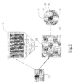
Fig. 2 is a block diagram of the control mechanism of the scope ofFig. 1 ; and -
Figs. 3A to 3F show various reticle patterns which may be displayed by the scope ofFig. 1 . - As shown in
Fig. 1 , a scope according to a preferred embodiment of the present invention is generally designated as 20. Thescope 20 is in general shape of acylindrical tube 22 with an ocular lens 4 and anobject lens 8. Light 9 from the outside environment, e.g. from a target falls on theobject lens 8, to be viewed by auser 5 through the ocular lens 4. - A display panel 6 (which may be a liquid crystal display (LCD), organic light-emitting diode (OLED) display, light-emitting diode (LED) dot matrix display, or such like light-generating display) fixed to the
tube 22 may be operated to generate a number of different reticle-patterns. Light 10 generated by the display panel 6 is directed by anoptical prism 7 onto theobject lens 8, again to be viewed by theuser 5 through the ocular lens 4. Theuser 5 would thus see the reticle-pattern imposed on the image of the target on thelens 8. - A printed circuit board (PCB) 2 mounted with a microcontroller (MCU) (not shown) is electrically connected with the display panel 6 for controlling the operation of the display panel 6. A
selection panel 3 is also electrically connected with the MCU for controlling the operation of the MCU. - As shown in
Fig. 2 , the electronics arrangement of thescope 22 includes a Power 11 (which may be dry batteries) which provides electric power to the display panel 6 and theMCU 12. A user, by operating a number of buttons 3a, 3b, 3c, 3d, 3e on theselection panel 3, may activate or deactivate the multi-reticle function of thescope 22, choose the reticle-pattern to be displayed, adjust the intensity of the light generated by the display panel 6, effect rotation of the displayed reticle-pattern, or adjust the scale or size of the displayed reticle-pattern. - The
MCU 12 has an electrically erasable programmable read-only memory (EEPROM) for storing the instructions for displaying plurality of reticle-patterns. Such may also be stored in a flash memory. -
Figs. 3A to 3F show a number of different reticle-patterns which may be displayed by thescope 22. Each pattern is formed of an array of lighting elements arranged in a matrix form of n columns and m rows. The MCU 12 operates the activation or otherwise of each lighting element in each pixel of the matrix. The initial position of the column and row address (0, 0) normally locates at the topleft hand corner 16 of the matrix. Using the reticle-pattern inFig. 3A as an example, to display such a pattern, the MCU 12 activates the lighting element at 14 but deactivates the lighting element at 15. - It can be seen that, with a scope according to the present invention, as the display panel 6 is fixed to the
scope 22, dislocation of the reticle-pattern relative to thescope 22 is prevented. In addition, with the use of a dot-matrix display panel, up to a hundred of different reticle-patterns can be easily produced, according to the user's preference and need, whereas in traditional mechanically-mounted multi-reticle mechanisms, it is very difficult to provide more than ten different reticle-patterns. It is also relatively easy to add in new reticle-patterns to the EEPROM or such like memory in theMCU 12. - It should be understood that the above only illustrates an example whereby the present invention may be carried out, and that various modifications and/or alterations may be made thereto without departing from the spirit of the invention.
- It should also be understood that various features of the invention which are, for brevity, described here in the context of a single embodiment, may also be provided separately or in any appropriate sub-combinations.
Claims (5)
- A scope (20) including :a display (6) adapted to display a plurality of reticle-patterns;means (2, 3) for selecting one of said plurality of reticle-patterns to be displayed by said display; andoptical arrangement (7) for projecting the displayed reticle-pattern onto a piece of lens (8) viewable by a user.
- A scope according to Claim 1 further including memory for storing said plurality of reticle-patterns.
- A scope according to Claim 1 wherein said display (6) is a liquid crystal display (LCD), organic light-emitting diode (OLED) display, light-emitting diode (LED) dot matrix display.
- A scope according to Claim 1 wherein said optical arrangement includes at least an optical prism (7).
- A scope according to Claim 1 wherein said piece of lens is an object lens (8).
Applications Claiming Priority (1)
| Application Number | Priority Date | Filing Date | Title |
|---|---|---|---|
| US11/849,639 US20090059219A1 (en) | 2007-09-04 | 2007-09-04 | Electronic Multi-Reticle Pattern Scope |
Publications (1)
| Publication Number | Publication Date |
|---|---|
| EP2034350A2 true EP2034350A2 (en) | 2009-03-11 |
Family
ID=40184998
Family Applications (1)
| Application Number | Title | Priority Date | Filing Date |
|---|---|---|---|
| EP08152894A Withdrawn EP2034350A2 (en) | 2007-09-04 | 2008-03-18 | Electronic multi-reticle-pattern scope |
Country Status (2)
| Country | Link |
|---|---|
| US (1) | US20090059219A1 (en) |
| EP (1) | EP2034350A2 (en) |
Cited By (2)
| Publication number | Priority date | Publication date | Assignee | Title |
|---|---|---|---|---|
| WO2011003814A1 (en) * | 2009-07-08 | 2011-01-13 | Gs Development Ab | Fire-control system |
| EP2694906A1 (en) * | 2011-04-03 | 2014-02-12 | IPU Industries Ltd | Firearm gun-sight |
Families Citing this family (7)
| Publication number | Priority date | Publication date | Assignee | Title |
|---|---|---|---|---|
| USD749085S1 (en) * | 2011-08-23 | 2016-02-09 | Sony Corporation | Display panel or screen with graphical user interface |
| USD731543S1 (en) * | 2012-07-03 | 2015-06-09 | Fujifilm Corporation | Digital camera display screen with graphical user interface |
| USD783675S1 (en) * | 2013-11-18 | 2017-04-11 | Mitsubishi Electric Corporation | Information display for an automotive vehicle with a computer generated icon |
| USD788163S1 (en) * | 2015-04-29 | 2017-05-30 | Samsung Electronics Co., Ltd. | Display screen or portion thereof with graphical user interface |
| USD788162S1 (en) * | 2015-04-29 | 2017-05-30 | Samsung Electronics Co., Ltd. | Display screen or portion thereof with graphical user interface |
| AU2019256715B2 (en) * | 2018-04-20 | 2025-01-02 | Sheltered Wings, Inc. D/B/A Vortex Optics | Viewing optic with direct active reticle targeting |
| US12247808B2 (en) * | 2021-09-28 | 2025-03-11 | Sig Sauer, Inc. | Reflex sight having emitter array |
Family Cites Families (6)
| Publication number | Priority date | Publication date | Assignee | Title |
|---|---|---|---|---|
| US3885861A (en) * | 1972-10-02 | 1975-05-27 | Hughes Aircraft Co | Liquid crystal digital reticle |
| GB9620001D0 (en) * | 1996-09-25 | 1996-11-13 | Firearms Research Ltd | Optical sighting devices |
| FR2760831B1 (en) * | 1997-03-12 | 1999-05-28 | Marie Christine Bricard | SELF-SHOOTING RIFLE FOR INDIVIDUAL WEAPON WITH AUTOMATIC FOCUS |
| US6516551B2 (en) * | 2000-12-27 | 2003-02-11 | American Technologies Network Corporation | Optical sight with switchable reticle |
| TWI464361B (en) * | 2005-11-01 | 2014-12-11 | Leupold & Stevens Inc | Ballistic ranging methods and systems for inclined shooting |
| US7926219B2 (en) * | 2007-01-05 | 2011-04-19 | Paul Kevin Reimer | Digital scope with horizontally compressed sidefields |
-
2007
- 2007-09-04 US US11/849,639 patent/US20090059219A1/en not_active Abandoned
-
2008
- 2008-03-18 EP EP08152894A patent/EP2034350A2/en not_active Withdrawn
Cited By (4)
| Publication number | Priority date | Publication date | Assignee | Title |
|---|---|---|---|---|
| WO2011003814A1 (en) * | 2009-07-08 | 2011-01-13 | Gs Development Ab | Fire-control system |
| US9115956B2 (en) | 2009-07-08 | 2015-08-25 | Gs Development Ab | Fire-control system |
| US9574849B2 (en) | 2009-07-08 | 2017-02-21 | Aimpoint Ab | Fire-control system |
| EP2694906A1 (en) * | 2011-04-03 | 2014-02-12 | IPU Industries Ltd | Firearm gun-sight |
Also Published As
| Publication number | Publication date |
|---|---|
| US20090059219A1 (en) | 2009-03-05 |
Similar Documents
| Publication | Publication Date | Title |
|---|---|---|
| US20090059219A1 (en) | Electronic Multi-Reticle Pattern Scope | |
| EP1723382B1 (en) | Weapon sight having multi-munitions ballistic computer | |
| US7171776B2 (en) | Weapon sight having analog on-target indicators | |
| US7490430B2 (en) | Device with multiple sights for respective different munitions | |
| US7269920B2 (en) | Weapon sight with ballistics information persistence | |
| US11859947B2 (en) | Targeting system | |
| US7614156B1 (en) | Bow-mounted sight with range finder and data storage means | |
| CN110770529B (en) | Targeting system | |
| US9146076B2 (en) | Dot sight device having power saving functions, the control method thereof | |
| JP2025531699A (en) | Adjustable weapon sight system and control method | |
| SE0402472L (en) | Device for automatic setting of optical sight for firearms | |
| US20180023921A1 (en) | Optoelectronic gunsight | |
| HK1123856A (en) | Electronic multi-reticle-pattern scope | |
| US11662176B2 (en) | Thermal gunsights | |
| US20200232764A1 (en) | Automatic bow sight | |
| US20050241207A1 (en) | Common aperture time-division-multiplexed laser rangefinder | |
| ES2927321T3 (en) | Ballistic correction device for weapon sight members | |
| CN205679134U (en) | Portable school gun apparatus | |
| RU192653U1 (en) | DEVICE FOR CHANGING THE APPEARANCE AND POSITION OF THE SIGHT BRAND | |
| KR20190071420A (en) | Aligning Apparatus of Gun | |
| WO2007030101A1 (en) | Weapon sight with ballistics information persistence | |
| JP2008256836A (en) | Light beam pointer | |
| RU2017113934A (en) | DEVICE FOR CHANGING THE APPEARANCE AND POSITION OF THE SIGHT BRAND | |
| WO2015186552A1 (en) | Optical characteristic measurement device and control method therefor | |
| RU2005131162A (en) | LIGHT Emitting Element for Optical Sight |
Legal Events
| Date | Code | Title | Description |
|---|---|---|---|
| PUAI | Public reference made under article 153(3) epc to a published international application that has entered the european phase |
Free format text: ORIGINAL CODE: 0009012 |
|
| AK | Designated contracting states |
Kind code of ref document: A2 Designated state(s): AT BE BG CH CY CZ DE DK EE ES FI FR GB GR HR HU IE IS IT LI LT LU LV MC MT NL NO PL PT RO SE SI SK TR |
|
| AX | Request for extension of the european patent |
Extension state: AL BA MK RS |
|
| REG | Reference to a national code |
Ref country code: HK Ref legal event code: DE Ref document number: 1123856 Country of ref document: HK |
|
| STAA | Information on the status of an ep patent application or granted ep patent |
Free format text: STATUS: THE APPLICATION IS DEEMED TO BE WITHDRAWN |
|
| 18D | Application deemed to be withdrawn |
Effective date: 20101001 |
|
| REG | Reference to a national code |
Ref country code: HK Ref legal event code: WD Ref document number: 1123856 Country of ref document: HK |