EP2034184A2 - Pumping Apparatus - Google Patents
Pumping Apparatus Download PDFInfo
- Publication number
- EP2034184A2 EP2034184A2 EP08163593A EP08163593A EP2034184A2 EP 2034184 A2 EP2034184 A2 EP 2034184A2 EP 08163593 A EP08163593 A EP 08163593A EP 08163593 A EP08163593 A EP 08163593A EP 2034184 A2 EP2034184 A2 EP 2034184A2
- Authority
- EP
- European Patent Office
- Prior art keywords
- pumping
- pressure region
- fluid
- housing
- pumping member
- Prior art date
- Legal status (The legal status is an assumption and is not a legal conclusion. Google has not performed a legal analysis and makes no representation as to the accuracy of the status listed.)
- Withdrawn
Links
- 238000005086 pumping Methods 0.000 title claims abstract description 120
- 239000012530 fluid Substances 0.000 claims abstract description 60
- 238000006243 chemical reaction Methods 0.000 claims description 46
- 239000000314 lubricant Substances 0.000 claims description 5
- 230000003247 decreasing effect Effects 0.000 claims description 3
- 230000015572 biosynthetic process Effects 0.000 description 3
- 238000005755 formation reaction Methods 0.000 description 3
- 238000005461 lubrication Methods 0.000 description 2
- 238000000034 method Methods 0.000 description 2
- 230000006835 compression Effects 0.000 description 1
- 238000007906 compression Methods 0.000 description 1
- 230000000694 effects Effects 0.000 description 1
- 238000012986 modification Methods 0.000 description 1
- 230000004048 modification Effects 0.000 description 1
Images



Classifications
-
- F—MECHANICAL ENGINEERING; LIGHTING; HEATING; WEAPONS; BLASTING
- F04—POSITIVE - DISPLACEMENT MACHINES FOR LIQUIDS; PUMPS FOR LIQUIDS OR ELASTIC FLUIDS
- F04C—ROTARY-PISTON, OR OSCILLATING-PISTON, POSITIVE-DISPLACEMENT MACHINES FOR LIQUIDS; ROTARY-PISTON, OR OSCILLATING-PISTON, POSITIVE-DISPLACEMENT PUMPS
- F04C2/00—Rotary-piston machines or pumps
- F04C2/08—Rotary-piston machines or pumps of intermeshing-engagement type, i.e. with engagement of co-operating members similar to that of toothed gearing
- F04C2/10—Rotary-piston machines or pumps of intermeshing-engagement type, i.e. with engagement of co-operating members similar to that of toothed gearing of internal-axis type with the outer member having more teeth or tooth-equivalents, e.g. rollers, than the inner member
- F04C2/102—Rotary-piston machines or pumps of intermeshing-engagement type, i.e. with engagement of co-operating members similar to that of toothed gearing of internal-axis type with the outer member having more teeth or tooth-equivalents, e.g. rollers, than the inner member the two members rotating simultaneously around their respective axes
-
- F—MECHANICAL ENGINEERING; LIGHTING; HEATING; WEAPONS; BLASTING
- F04—POSITIVE - DISPLACEMENT MACHINES FOR LIQUIDS; PUMPS FOR LIQUIDS OR ELASTIC FLUIDS
- F04C—ROTARY-PISTON, OR OSCILLATING-PISTON, POSITIVE-DISPLACEMENT MACHINES FOR LIQUIDS; ROTARY-PISTON, OR OSCILLATING-PISTON, POSITIVE-DISPLACEMENT PUMPS
- F04C14/00—Control of, monitoring of, or safety arrangements for, machines, pumps or pumping installations
- F04C14/24—Control of, monitoring of, or safety arrangements for, machines, pumps or pumping installations characterised by using valves controlling pressure or flow rate, e.g. discharge valves or unloading valves
- F04C14/26—Control of, monitoring of, or safety arrangements for, machines, pumps or pumping installations characterised by using valves controlling pressure or flow rate, e.g. discharge valves or unloading valves using bypass channels
-
- F—MECHANICAL ENGINEERING; LIGHTING; HEATING; WEAPONS; BLASTING
- F04—POSITIVE - DISPLACEMENT MACHINES FOR LIQUIDS; PUMPS FOR LIQUIDS OR ELASTIC FLUIDS
- F04C—ROTARY-PISTON, OR OSCILLATING-PISTON, POSITIVE-DISPLACEMENT MACHINES FOR LIQUIDS; ROTARY-PISTON, OR OSCILLATING-PISTON, POSITIVE-DISPLACEMENT PUMPS
- F04C2/00—Rotary-piston machines or pumps
- F04C2/08—Rotary-piston machines or pumps of intermeshing-engagement type, i.e. with engagement of co-operating members similar to that of toothed gearing
- F04C2/082—Details specially related to intermeshing engagement type machines or pumps
- F04C2/084—Toothed wheels
-
- F—MECHANICAL ENGINEERING; LIGHTING; HEATING; WEAPONS; BLASTING
- F04—POSITIVE - DISPLACEMENT MACHINES FOR LIQUIDS; PUMPS FOR LIQUIDS OR ELASTIC FLUIDS
- F04C—ROTARY-PISTON, OR OSCILLATING-PISTON, POSITIVE-DISPLACEMENT MACHINES FOR LIQUIDS; ROTARY-PISTON, OR OSCILLATING-PISTON, POSITIVE-DISPLACEMENT PUMPS
- F04C2240/00—Components
- F04C2240/60—Shafts
Definitions
- This invention relates to a pumping apparatus. More particularly but not exclusively the invention relates to a oil pumping assembly for providing oil for lubrication in an engine. However the invention may be applied to a wide variety of other pumping apparatus which pump fluid from a lower pressure region to a high pressure region.
- Pumping apparatus which include relief devices to enable any excess pressure fluid to be relieved. This in the event of the pumping apparatus providing excess fluid, and/or over pressure fluid, the high pressure is relieved.
- known pumping apparatus which include such features tend to be large as such relief devices essentially are separate from the pumping components of the pumping apparatus.
- the invention provides another advantage over conventional arrangements in which excess fluid/pressure at the higher pressure region is vented to the sump for example, because the higher pressure fluid is relieved to the lower pressure region of the pumping apparatus so that its pressure is not lost. This provides for more efficient use of the engine.
- the invention may be applied to a wide variety of pumping apparatus types, the invention may particularly be applied to a geroter type pumping apparatus e.g. which includes in the housing, in addition to the pumping member, a reaction member, the reaction member receiving the pumping member therein, and the pumping member and reaction member being relatively rotatable in the housing to provide between them spaces.
- a geroter type pumping apparatus e.g. which includes in the housing, in addition to the pumping member, a reaction member, the reaction member receiving the pumping member therein, and the pumping member and reaction member being relatively rotatable in the housing to provide between them spaces.
- the spaces may increase in volume thus to draw fluid into the spaces.
- the spaces may decrease in volume thus expelling fluid out of the spaces, towards the outlet.
- the pumping apparatus may be a geroter pumping apparatus which includes nested hypocycloid inner and outer gear elements being respectively, the pumping member and the reaction member.
- the pumping member may include a plurality of gear teeth which cooperate with the gear teeth of the reaction member to provide the spaces of increasing volumes as the pumping member and reaction member relatively rotate, into which fluid is drawn at the lower pressure region, and the spaces of decreasing volumes from which fluid is expelled at the higher pressure region.
- the reaction member may have a differing number of gear teeth to the pumping member, i.e. more gear teeth, and the pumping member and the reaction member may be mounted in the housing so as to rotate about spaced parallel rotational axes. Desirably the pumping member is driven and the reaction member is thus rotated in the housing, by the rotating pumping member, but at a differential rotational speed to the pumping member due to the greater number of gear teeth.
- the support may include a hollow shaft on which the pumping member is driven, the shaft being fixed to the pumping member and to a drive member such as a drive gear.
- the shaft may include a plurality of apertures which communicate on the exterior of the shaft, with the higher pressure region and the lower pressure region.
- a hollow piston which may have a plurality of apertures which may communicate with the apertures of the shaft when the fluid pressure at the higher pressure region exceeds a threshold value.
- the housing provides a passage for fluid from the higher pressure region to bear on the piston to move the piston in the hollow of the shaft to a condition in which the respective apertures are aligned, with such movement being resisted by a resilient device such as a spring which may act between the shaft and the piston.
- the pumping member includes in an end face of the pumping member, an annular recess which surrounds the shaft and which communicates at one circumferential location with the lower pressure region and with the apertures in the support, and which recess communicates at a second circumferential location with the higher pressure region and with the apertures of the support, so that the fluid may pass from the higher pressure region to the support, and when the apertures of the support and the piston are aligned, through the support to the lower pressure region.
- the housing may include first and second bridge parts which are received in the annular recess at generally radially opposite locations to prevent the flow of fluid from the higher pressure region to the lower pressure region via the recess without passing through the support.
- the housing of the pumping apparatus may include a first part which provides for the inlet connections from the lower pressure region to a fluid source, and an outlet connection from the higher pressure region to a delivery connection, and a second part which at least substantially contains the pumping member, and the reaction member where provided.
- a pumping apparatus 10 includes a housing 11 which is mounted for example, in an engine compartment of a vehicle or machine, the housing 11 including a first part 12 which provides an inlet connection 12a to a fluid source such as an oil sump S of an engine E (see figure 9 ), and an outlet connection 12b to galleries G of the engine E which require lubricant.
- a fluid source such as an oil sump S of an engine E (see figure 9 )
- an outlet connection 12b to galleries G of the engine E which require lubricant.
- the housing 11 includes a second part 14 in which are received for rotation, a pumping member 16 and a reaction member 18, the pumping member 16 being received in an opening 18a of the reaction member 18.
- the reaction member 18 is constrained by the housing 12 to rotate about a first rotational axis A, whilst the pumping member 16 is relatively eccentrically mounted for rotation about a second rotational axis B which is displaced relative to axis A, but is generally parallel to the axis A.
- the pumping member 16 is driven by a gear 20 from a prime mover, such as an output gear from a driven shaft of the engine E, there being a support 22 which carries the pumping member 16 and is connected for driving to the gear 20, through an opening 14a provided in a base 15 of the second housing part 14.
- the pumping member 16 includes a plurality of lobular gear teeth, in this example six teeth 24 which provide between them, recesses 25.
- the opening 18a of the reaction member 18 includes seven corresponding lobular gear teeth 27, each of which may, at some positions of rotation at least relative to the pumping member 16, be received in a recess 25 between a pair of the gear teeth 24 of the pumping member 16.
- the tooth of the pumping member 16 which is indicated at 24a is wholly received in a recess between a pair of the gear teeth 27a, 27b of the reaction member 18.
- the pumping apparatus 10 shown and described is a geroter pumping apparatus of the nested hypocycloid kind, with the pumping member 16 being an inner nested geared element and the reaction member 18 being an outer nested geared element.
- first spaces 31 of increasing size as the pumping member 16 and reaction member 18 relatively rotate will be provided between the pumping member 16 and the reaction member 18, whilst at a location to the other side of the dividing line D, second spaces 33 of decreasing size as the pumping member 16 and reaction member 18 relatively rotate will be provided.
- the fluid pressure in the first spaces 31 is lower pressure fluid, whilst the fluid pressure in the second spaces 33 is higher pressure fluid.
- the first spaces 31 each communicate with the inlet connection 12a to the fluid source S and thus this is the pump apparatus 10 fluid inlet.
- the second spaces 33 communicate with the outlet connection 12b to the engine galleries G or other equipment to be fed the fluid e.g. for lubrication, and thus this connection 12b is the pump apparatus 10 outlet.
- the first and second housing parts 12, 14 provide a low pressure region inlet port 35 which extends to either side of the pumping member 16 and which is connected to the inlet connection 12a to the fluid source S and to the inlet spaces 31, and a higher pressure regions outlet port 36 which extends to either side of the pumping member 16 and which is connected to the outlet connection 12b.
- the support 22 includes a hollow shaft 41 which extends through and is fixed to the pumping member 16, and extends through the opening 14a in the base of the second housing part 14, and is fixed to gear 20.
- the shaft 41 includes a plurality of circumferentially spaced apertures 44 which lie adjacent to an annular recess 45 which is provided in the pumping member 16 in a face 46 thereof which faces inwardly of the second housing part 14a.
- the circumferential recess 45 of the pumping member 16 communicates with, on the one hand the lower pressure region 35, and on the other hand with the higher pressure region 36.
- the second housing part 14 includes formations which are received in the annular recess 45 to prevent the flow of fluid from the higher pressure region 36 to the lower pressure region 35 other than through the support 22.
- These formations include a first bridge part b1 (best seen in figure 6 ) which at one circumferential location is received in and closes the annular recess 45, and a second bridge part b2 which is received in and closes the annular recess 45 at a second circumferential location.
- the annular recess 45 communicates with, on the one hand the lower pressure region 35 and on the other hand with the higher pressure region 36.
- a piston 43 which is slidable axially inside the hollow of the shaft 41.
- the piston 43 has a closed end 42 and an internal hollow 47, and there is a compression spring 50 provided in the hollow 47 of the piston 43 which acts between a closed end 41 a of the shaft 41 and the closed end 42 of the piston 43, to urge the piston 43 outwardly of the hollow of the shaft 41.
- the piston 43 is prevented from being urged fully outwardly of the hollow of the shaft 41 by a circlip 47a, although the piston 43 might alternatively bear on a bearing part of the first housing part 12 as required.
- the higher pressure region outlet port 36 includes a passage 36a which extends to a position of the first housing part 12 adjacent the closed end 42 of the piston 43.
- the fluid of the higher pressure outlet region 36 bears on the closed end 42 of the piston 43 to urge the piston 43 against the force of the spring 50, inwardly of the hollow of the shaft 41.
- the piston 43 includes a plurality of circumferentially spaced apertures 52 to the internal hollow 47 of the piston 43 which desirably correspond in number and size to the apertures 44 of the shaft 41. If the piston 43 is urged inwardly of the hollow of the shaft 41 sufficiently, the apertures 52 of the piston 43 and the apertures 44 of the shaft 41 will therefore align, and thus a fluid flow path will be provided through the support 22 from the annular recess 45 between the bridge parts b1, b2 which communicate with the higher pressure region 36, to the annular recess 45 between the bridge parts b1, b2 which communicate with the lower pressure region 35 so that higher pressure fluid from the higher pressure region 36 can be relieved to the lower pressure region 35.
- a very compact pumping apparatus 10 for its pumping rating may be provided.
- the configuration of the pumping apparatus 10 shown is purely exemplary.
- the first housing part 12 closes the second housing part 14, and in the manner of a manifold provides formations for the lower pressure region inlet 35 and higher pressure region outlet 36 ports, as well as the connections 12a and 12b to respectively the fluid source S and engine galleries G to be lubricated.
- the pumping apparatus 10 may be differently configured to contain the pumping member 16 and the reaction member 18 and to provide inlet and outlet ports 35, 36.
- the pumping member has six gear teeth 24 and the reaction member 18 seven teeth 27, but in another configuration different numbers of teeth 24 and 27 may be provided, although with a nested hypocycloid type pumping apparatus 10 as described, the reaction member 18 would require at least one additional tooth 27 to the pumping member 24.
- the invention may be applied to other geroter pumping apparatus or indeed to any pumping apparatus which include a pumping member 16 which rotates, with or without a reaction member 18, in a housing 11 to perform pumping between a lower pressure region and a higher pressure region.
- the invention may be applied to a gear pump which includes a pair of meshing gear elements, the fluid flow path from the higher pressure region to the lower pressure region being through a support of at least one of the meshing gears.
- a flow path for fluid is provided from a higher pressure region to a lower pressure region through the support 22 which carries the or a pumping member 16, at least when the outlet pressure exceeds a threshold pressure.
- the engine E is seen to be an engine by way of example only, for a working machine W which include a body Y which includes the engine E compartment and a cab C, mounted for rotation about an upright axis R on a ground engaging structure L which in the example includes a continuous track T driven by wheels X.
- the machine W has a working arm P with a working implement, configured for excavating.
- the invention may be applied to a wide variety of working machines and other vehicles, including automotive vehicles, as required, for pumping lubricant.
- the invention may be used for pumping apparatus which pump other fluids than lubricant.
Landscapes
- Engineering & Computer Science (AREA)
- Mechanical Engineering (AREA)
- General Engineering & Computer Science (AREA)
- Physics & Mathematics (AREA)
- Fluid Mechanics (AREA)
- Rotary Pumps (AREA)
- Details And Applications Of Rotary Liquid Pumps (AREA)
Abstract
Description
- This invention relates to a pumping apparatus. More particularly but not exclusively the invention relates to a oil pumping assembly for providing oil for lubrication in an engine. However the invention may be applied to a wide variety of other pumping apparatus which pump fluid from a lower pressure region to a high pressure region.
- Pumping apparatus are known which include relief devices to enable any excess pressure fluid to be relieved. This in the event of the pumping apparatus providing excess fluid, and/or over pressure fluid, the high pressure is relieved. However known pumping apparatus which include such features tend to be large as such relief devices essentially are separate from the pumping components of the pumping apparatus.
- According to a first aspect of the invention we provide a pumping apparatus according to claim 1.
- Thus in a pumping apparatus of the invention, pressure is relieved from the higher pressure to the lower pressure region via the support which is an integral pumping component. Thus a more compact pumping apparatus may be provided than a contemporary pumping apparatus.
- The invention provides another advantage over conventional arrangements in which excess fluid/pressure at the higher pressure region is vented to the sump for example, because the higher pressure fluid is relieved to the lower pressure region of the pumping apparatus so that its pressure is not lost. This provides for more efficient use of the engine.
- Although the invention may be applied to a wide variety of pumping apparatus types, the invention may particularly be applied to a geroter type pumping apparatus e.g. which includes in the housing, in addition to the pumping member, a reaction member, the reaction member receiving the pumping member therein, and the pumping member and reaction member being relatively rotatable in the housing to provide between them spaces. At one rotational position relative to the housing, adjacent the lower pressure fluid region inlet, as the pumping member and reaction member relatively rotate, the spaces may increase in volume thus to draw fluid into the spaces.
- At another position relative to the housing, adjacent the higher pressure fluid region, as the pumping member and reaction member relatively rotate, the spaces may decrease in volume thus expelling fluid out of the spaces, towards the outlet.
- Thus in one embodiment the pumping apparatus may be a geroter pumping apparatus which includes nested hypocycloid inner and outer gear elements being respectively, the pumping member and the reaction member.
- Thus the pumping member may include a plurality of gear teeth which cooperate with the gear teeth of the reaction member to provide the spaces of increasing volumes as the pumping member and reaction member relatively rotate, into which fluid is drawn at the lower pressure region, and the spaces of decreasing volumes from which fluid is expelled at the higher pressure region. The reaction member may have a differing number of gear teeth to the pumping member, i.e. more gear teeth, and the pumping member and the reaction member may be mounted in the housing so as to rotate about spaced parallel rotational axes. Desirably the pumping member is driven and the reaction member is thus rotated in the housing, by the rotating pumping member, but at a differential rotational speed to the pumping member due to the greater number of gear teeth.
- The support may include a hollow shaft on which the pumping member is driven, the shaft being fixed to the pumping member and to a drive member such as a drive gear. The shaft may include a plurality of apertures which communicate on the exterior of the shaft, with the higher pressure region and the lower pressure region.
- Within the hollow of the shaft there may be provided a hollow piston which may have a plurality of apertures which may communicate with the apertures of the shaft when the fluid pressure at the higher pressure region exceeds a threshold value. Desirably the housing provides a passage for fluid from the higher pressure region to bear on the piston to move the piston in the hollow of the shaft to a condition in which the respective apertures are aligned, with such movement being resisted by a resilient device such as a spring which may act between the shaft and the piston.
- Thus as the fluid pressure in the higher pressure region increases, the piston will be moved against the force of the spring to the condition in which the respective apertures of the shaft and the piston are in alignment.
- Desirably, the pumping member includes in an end face of the pumping member, an annular recess which surrounds the shaft and which communicates at one circumferential location with the lower pressure region and with the apertures in the support, and which recess communicates at a second circumferential location with the higher pressure region and with the apertures of the support, so that the fluid may pass from the higher pressure region to the support, and when the apertures of the support and the piston are aligned, through the support to the lower pressure region. The housing may include first and second bridge parts which are received in the annular recess at generally radially opposite locations to prevent the flow of fluid from the higher pressure region to the lower pressure region via the recess without passing through the support.
- The housing of the pumping apparatus may include a first part which provides for the inlet connections from the lower pressure region to a fluid source, and an outlet connection from the higher pressure region to a delivery connection, and a second part which at least substantially contains the pumping member, and the reaction member where provided.
- According to a second aspect of the invention we provide a working machine according to
claim 11. - Embodiments of the invention will now be described with reference to the accompanying drawings in which:-
-
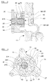
FIGURE 1 is an exploded perspective view of a part of a pumping apparatus in accordance with the invention, excluding a first housing part; -
FIGURE 2 is a cross sectional view on the line A-A offigure 8 of the apparatus offigure 1 shown assembled complete with the first housing part; -
FIGURE 3 is a cross section on the line F-F offigure 2 ; -
FIGURE 4 is a cross section on the line C-C offigure 2 ; -
FIGURE 5 is a cross section on the line D-D offigure 2 ; -
FIGURE 6 is a cross section on the line E-E offigure 2 ; -
FIGURE 7 is a cross section on the line G-G offigure 2 ; -
FIGURE 8 is a front view of the apparatus offigure 2 with the first housing part removed; -
FIGURE 9 is an illustrative view of a working machine including the pumping apparatus of the previous figures. - Referring to the drawings a
pumping apparatus 10 includes ahousing 11 which is mounted for example, in an engine compartment of a vehicle or machine, thehousing 11 including afirst part 12 which provides aninlet connection 12a to a fluid source such as an oil sump S of an engine E (seefigure 9 ), and anoutlet connection 12b to galleries G of the engine E which require lubricant. - The
housing 11 includes asecond part 14 in which are received for rotation, apumping member 16 and areaction member 18, the pumpingmember 16 being received in an opening 18a of thereaction member 18. - The
reaction member 18 is constrained by thehousing 12 to rotate about a first rotational axis A, whilst thepumping member 16 is relatively eccentrically mounted for rotation about a second rotational axis B which is displaced relative to axis A, but is generally parallel to the axis A. In this example, thepumping member 16 is driven by agear 20 from a prime mover, such as an output gear from a driven shaft of the engine E, there being asupport 22 which carries thepumping member 16 and is connected for driving to thegear 20, through an opening 14a provided in abase 15 of thesecond housing part 14. - The
pumping member 16 includes a plurality of lobular gear teeth, in this example sixteeth 24 which provide between them, recesses 25. The opening 18a of thereaction member 18 includes seven correspondinglobular gear teeth 27, each of which may, at some positions of rotation at least relative to thepumping member 16, be received in arecess 25 between a pair of thegear teeth 24 of thepumping member 16. In the example, which shows thepumping member 16 and thereaction member 18 in one relative position, the tooth of thepumping member 16 which is indicated at 24a is wholly received in a recess between a pair of thegear teeth reaction member 18. As the pumpingmember 16 andreaction member 18 relatively rotate further, both in an anti-clockwise direction as seen in the drawings, due to their displaced axes of rotation B, A respectively, thegear tooth 24a of thepumping member 16 will disengage the recess betweenteeth reaction member 18 so that when the pumpingmember 16 has rotated 180°, thetooth 24a will have rotated to theposition 24b shown where it lies adjacent the tooth indicated at 27 of thereaction member 18 as thereaction member 18 will not have rotated the same amount. - It will be appreciated that by driving the pumping
member 16, by virtue of agear tooth 24a of the pumpingmember 16 always being fully received by a recess betweenteeth 27 of thereaction member 18 where the axis of rotation A of thepumping member 16 is closest to an inner wall 14b of thesecond housing part 14, thereaction member 18 will be driven by the pumpingmember 16 in the same rotational direction, but at a differential rotational speed as thepumping member 16, due to theadditional tooth 27. - Thus the
pumping apparatus 10 shown and described is a geroter pumping apparatus of the nested hypocycloid kind, with the pumpingmember 16 being an inner nested geared element and thereaction member 18 being an outer nested geared element. - Moreover as the pumping
member 16 andreaction member 18 relatively rotate about their respective axes A, B, at a location to one side of a line indicated at D,first spaces 31 of increasing size as thepumping member 16 andreaction member 18 relatively rotate, will be provided between the pumpingmember 16 and thereaction member 18, whilst at a location to the other side of the dividing line D,second spaces 33 of decreasing size as the pumpingmember 16 andreaction member 18 relatively rotate will be provided. - As will be explained below, the fluid pressure in the
first spaces 31 is lower pressure fluid, whilst the fluid pressure in thesecond spaces 33 is higher pressure fluid. - The
first spaces 31 each communicate with theinlet connection 12a to the fluid source S and thus this is thepump apparatus 10 fluid inlet. Thesecond spaces 33 communicate with theoutlet connection 12b to the engine galleries G or other equipment to be fed the fluid e.g. for lubrication, and thus thisconnection 12b is thepump apparatus 10 outlet. - It will be appreciated that as the pumping
member 16 andreaction member 18 relatively rotate as described, fluid will be drawn into or flow into the low pressure region of the pumping apparatus i.e.first spaces 31 asfirst spaces 31 volumes increase, and fluid will be expelled from thesecond spaces 33 as thesecond spaces 33 volumes decrease. - The first and
second housing parts region inlet port 35 which extends to either side of thepumping member 16 and which is connected to theinlet connection 12a to the fluid source S and to theinlet spaces 31, and a higher pressureregions outlet port 36 which extends to either side of thepumping member 16 and which is connected to theoutlet connection 12b. - According to the invention, in the event that the fluid pressure in the outlet port
higher pressure region 36 increases above a threshold, there is a path for the high pressure fluid to the low pressure region of theinlet port 35 to relieve the excess pressure, through thesupport 22 which will now be described. - The
support 22 includes ahollow shaft 41 which extends through and is fixed to the pumpingmember 16, and extends through the opening 14a in the base of thesecond housing part 14, and is fixed togear 20. - The
shaft 41 includes a plurality of circumferentially spacedapertures 44 which lie adjacent to anannular recess 45 which is provided in thepumping member 16 in aface 46 thereof which faces inwardly of thesecond housing part 14a. Thecircumferential recess 45 of the pumpingmember 16 communicates with, on the one hand thelower pressure region 35, and on the other hand with thehigher pressure region 36. - The
second housing part 14 includes formations which are received in theannular recess 45 to prevent the flow of fluid from thehigher pressure region 36 to thelower pressure region 35 other than through thesupport 22. These formations include a first bridge part b1 (best seen infigure 6 ) which at one circumferential location is received in and closes theannular recess 45, and a second bridge part b2 which is received in and closes theannular recess 45 at a second circumferential location. Between the bridge parts b1, b2, theannular recess 45 communicates with, on the one hand thelower pressure region 35 and on the other hand with thehigher pressure region 36. - However, below a threshold pressure, fluid flow into the hollow of the
shaft 41 through theapertures 44 in thesupport 22 is prevented by apiston 43 which is slidable axially inside the hollow of theshaft 41. Thepiston 43 has a closedend 42 and an internal hollow 47, and there is acompression spring 50 provided in the hollow 47 of thepiston 43 which acts between a closedend 41 a of theshaft 41 and the closedend 42 of thepiston 43, to urge thepiston 43 outwardly of the hollow of theshaft 41. Thepiston 43 is prevented from being urged fully outwardly of the hollow of theshaft 41 by acirclip 47a, although thepiston 43 might alternatively bear on a bearing part of thefirst housing part 12 as required. - It can be seen from
figure 2 that the higher pressureregion outlet port 36 includes apassage 36a which extends to a position of thefirst housing part 12 adjacent the closedend 42 of thepiston 43. Thus the fluid of the higherpressure outlet region 36 bears on the closedend 42 of thepiston 43 to urge thepiston 43 against the force of thespring 50, inwardly of the hollow of theshaft 41. - The
piston 43 includes a plurality of circumferentially spacedapertures 52 to the internal hollow 47 of thepiston 43 which desirably correspond in number and size to theapertures 44 of theshaft 41. If thepiston 43 is urged inwardly of the hollow of theshaft 41 sufficiently, theapertures 52 of thepiston 43 and theapertures 44 of theshaft 41 will therefore align, and thus a fluid flow path will be provided through thesupport 22 from theannular recess 45 between the bridge parts b1, b2 which communicate with thehigher pressure region 36, to theannular recess 45 between the bridge parts b1, b2 which communicate with thelower pressure region 35 so that higher pressure fluid from thehigher pressure region 36 can be relieved to thelower pressure region 35. - It will be appreciated that there will be a metering effect in that initially as the
apertures support 22 will be permitted, but as the outlet pressure increases, theapertures higher pressure region 36 to thelower pressure region 35. - By virtue of the flow path for fluid from the
higher pressure region 36 to thelower pressure region 35 through thesupport 22 as described, a verycompact pumping apparatus 10 for its pumping rating may be provided. - Various modifications may be made without departing from the scope of the invention.
- The configuration of the
pumping apparatus 10 shown is purely exemplary. In the example, thefirst housing part 12 closes thesecond housing part 14, and in the manner of a manifold provides formations for the lowerpressure region inlet 35 and higherpressure region outlet 36 ports, as well as theconnections pumping apparatus 10 may be differently configured to contain the pumpingmember 16 and thereaction member 18 and to provide inlet andoutlet ports - In the example, the pumping member has six
gear teeth 24 and thereaction member 18 seventeeth 27, but in another configuration different numbers ofteeth type pumping apparatus 10 as described, thereaction member 18 would require at least oneadditional tooth 27 to the pumpingmember 24. - Although the invention has been described in relation to a
geroter pumping apparatus 10 of the nested hypocycloid type, the invention may be applied to other geroter pumping apparatus or indeed to any pumping apparatus which include a pumpingmember 16 which rotates, with or without areaction member 18, in ahousing 11 to perform pumping between a lower pressure region and a higher pressure region. For example the invention may be applied to a gear pump which includes a pair of meshing gear elements, the fluid flow path from the higher pressure region to the lower pressure region being through a support of at least one of the meshing gears. - In each case though, a flow path for fluid is provided from a higher pressure region to a lower pressure region through the
support 22 which carries the or a pumpingmember 16, at least when the outlet pressure exceeds a threshold pressure. - The invention has been described in relation to a fluid pumping apparatus for pumping lubricant for an engine E and in
figure 9 , the engine E is seen to be an engine by way of example only, for a working machine W which include a body Y which includes the engine E compartment and a cab C, mounted for rotation about an upright axis R on a ground engaging structure L which in the example includes a continuous track T driven by wheels X. In the example offigure 9 , the machine W has a working arm P with a working implement, configured for excavating. However the invention may be applied to a wide variety of working machines and other vehicles, including automotive vehicles, as required, for pumping lubricant. However the invention may be used for pumping apparatus which pump other fluids than lubricant. - The features disclosed in the foregoing description, or the following claims, or the accompanying drawings, expressed in their specific forms or in terms of a means for performing the disclosed function, or a method or process for attaining the disclosed result, as appropriate, may, separately, or in any combination of such features, be utilised for realising the invention in diverse forms thereof.
Claims (11)
- A pumping apparatus (10) including a pump housing (11), a pumping member (16) which is rotatable in the housing (11) to pump fluid, the pumping member (16) being provided on a support (22) which is in use, driven, the housing (11) including in communication with an inlet (12a), a lower pressure region (35), and in communication with an outlet (12b), a higher pressure region (36), there being a passage for fluid from the higher pressure region (36) to the lower pressure region (35) through the support (22) when the fluid pressure in the higher pressure region (36) exceeds a threshold value.
- An apparatus according to claim 1 characterised in that the pumping apparatus (10) includes in the housing (11), in addition to the pumping member (16), a reaction member (18), the reaction member (18) receiving the pumping member (16) therein, and the pumping member (16) and reaction member (18) being relatively rotatable in the housing (11) to provide between the spaces (31,33).
- An apparatus according to claim 2 which is a geroter type pumping apparatus and wherein at one rotational position relative to the housing (11), adjacent the lower pressure fluid region inlet (12a), as the pumping member (16) and reaction member (18) relatively rotate, the spaces (31) increase in volume thus to draw fluid into the spaces (31), and at another position relative to the housing (11), adjacent the higher pressure fluid region (36), as the pumping member (16) and reaction member (18) relatively rotate, the spaces (33) decrease in volume thus expelling fluid out of the spaces (33), towards the outlet (12b).
- An apparatus according to claim 3 characterised in that the pumping apparatus includes nested hypocycloid inner and outer gear elements being respectively, the pumping member (16) and the reaction member (18), and the pumping member (16) includes a plurality of gear teeth (24) which cooperate with gear teeth (27) of the reaction member (18) to provide the spaces (31) of increasing volumes as the pumping member (16) and reaction member (18) relatively rotate, into which fluid is drawn at the lower pressure region (35), and the spaces (33) of decreasing volumes from which fluid is expelled at the higher pressure region (36), the reaction member (18) having a differing number of gear teeth (27) to the pumping member (16), the pumping member (16) and the reaction member (18) being mounted in the housing (11) so as to rotate about spaced parallel rotational axes (A,B).
- An apparatus according to claim characterised in that the pumping member (16) is driven and the reaction member (18) is thus rotated in the housing (11), by the rotating pumping member (16), but at a differential rotational speed to the pumping member (16) due to the greater number of gear teeth (27).
- An apparatus according to any one of the preceding claims characterised in that the support (22) incudes a hollow shaft (41) on which the pumping member (16) is driven, the shaft (41) being fixed to the pumping member (16) and to a drive member.
- An apparatus according to claim 6 characterised in that the shaft (22) includes a plurality of apertures (44) which communicate on the exterior of the shaft (22), with the higher pressure region (36) and the lower pressure region (35).
- An apparatus according to claim 7 characterised in that within the hollow of the shaft (41) there is provided a hollow piston (43) which has a plurality of apertures (52) which may communicate with the apertures (44) of the shaft (41) when the fluid pressure at the higher pressure region (36) exceeds a threshold value, and the housing (11) provides a passage (36a) for fluid from the higher pressure region (36) to bear on the piston (43) to move the piston (43) in the hollow of the shaft (41) to a condition in which the respective apertures (52,44) are aligned, with such movement being resisted by a resilient device (50) acting between the shaft (41) and the piston (43).
- An apparatus according to claim 7 or 8 wherein the pumping member (16) includes in an end face of the pumping member, an annular recess (45) which surrounds the shaft (41) and which communicates at one circumferential location with the lower pressure region (35) and with the apertures (44) in the support (22), and which recess (45) communicates at a second circumferential location with the higher pressure region (36) and with the apertures (44) of the support (22), and when the apertures (44) of the support (22) and the piston (43) are aligned, through the support (22) to the lower pressure region (35) and the housing (11) including first and second bridge parts (b1,b2) which are received in the annular recess (45) at generally radially opposite locations to prevent the flow of fluid from the higher pressure region (36) to the lower pressure region (35) via the recess (45) without passing through the support (22).
- An apparatus according to any one of the preceding claims characterised in that the housing (11) of the pumping apparatus (10) includes a first part (12) which provides for the inlet connections from the lower pressure region (35) to a fluid source (S), and an outlet connection (12b) from the higher pressure region (36) to a delivery connection, and a second part (14) which at least substantially contains the pumping member (16), and the reaction member (18) where provided.
- A working machine (W) which includes a ground engaging structure (L) by means of which the machine (W) is moveable over the ground, a working arm (P) which includes a working implement for performing working operations, an engine (E) for providing power at least for driving the machine (E), and wherein the engine (E) is lubricated by lubricant pumped by a pumping apparatus (10) according to any one of the preceding claims.
Applications Claiming Priority (1)
| Application Number | Priority Date | Filing Date | Title |
|---|---|---|---|
| GB0717196.0A GB2452493B (en) | 2007-09-05 | 2007-09-05 | Pumping apparatus |
Publications (2)
| Publication Number | Publication Date |
|---|---|
| EP2034184A2 true EP2034184A2 (en) | 2009-03-11 |
| EP2034184A3 EP2034184A3 (en) | 2012-03-21 |
Family
ID=38640218
Family Applications (1)
| Application Number | Title | Priority Date | Filing Date |
|---|---|---|---|
| EP08163593A Withdrawn EP2034184A3 (en) | 2007-09-05 | 2008-09-03 | Pumping Apparatus |
Country Status (4)
| Country | Link |
|---|---|
| US (1) | US8657592B2 (en) |
| EP (1) | EP2034184A3 (en) |
| CN (1) | CN101382135B (en) |
| GB (1) | GB2452493B (en) |
Cited By (1)
| Publication number | Priority date | Publication date | Assignee | Title |
|---|---|---|---|---|
| CN103388735A (en) * | 2013-07-30 | 2013-11-13 | 长城汽车股份有限公司 | Variable oil pump |
Family Cites Families (10)
| Publication number | Priority date | Publication date | Assignee | Title |
|---|---|---|---|---|
| GB816967A (en) * | 1956-11-28 | 1959-07-22 | Burman & Sons Ltd | Rotary pumps |
| DE2219587A1 (en) * | 1972-04-21 | 1973-10-25 | Teves Gmbh Alfred | VINGE CELL PUMP |
| DE2318080A1 (en) * | 1973-04-11 | 1974-10-31 | Teves Gmbh Alfred | PRESSURE MEDIUM PUMP |
| ES445021A1 (en) * | 1976-02-10 | 1977-06-01 | Bendiberica Sa | Gear pump |
| JPH06200722A (en) * | 1992-12-28 | 1994-07-19 | Suzuki Motor Corp | Engine oil pump |
| CN2535578Y (en) * | 2002-04-15 | 2003-02-12 | 周文华 | Cycloid type autombile fuel-oil pump core |
| AT413235B (en) * | 2003-10-09 | 2005-12-15 | Tcg Unitech Ag | ROTARY PISTON PUMP, PARTICULARLY GEAR PUMP |
| JP4366645B2 (en) * | 2003-11-06 | 2009-11-18 | アイシン精機株式会社 | Engine oil supply device |
| CN100357605C (en) | 2003-11-11 | 2007-12-26 | 上海师范大学 | Cycloidal pin gear hydraulic pump |
| GB0515494D0 (en) * | 2005-07-28 | 2005-08-31 | Bamford Excavators Ltd | Fluid pumping apparatus |
-
2007
- 2007-09-05 GB GB0717196.0A patent/GB2452493B/en not_active Expired - Fee Related
-
2008
- 2008-09-03 EP EP08163593A patent/EP2034184A3/en not_active Withdrawn
- 2008-09-04 US US12/204,678 patent/US8657592B2/en active Active
- 2008-09-05 CN CN2008102150366A patent/CN101382135B/en not_active Expired - Fee Related
Non-Patent Citations (1)
| Title |
|---|
| None * |
Cited By (1)
| Publication number | Priority date | Publication date | Assignee | Title |
|---|---|---|---|---|
| CN103388735A (en) * | 2013-07-30 | 2013-11-13 | 长城汽车股份有限公司 | Variable oil pump |
Also Published As
| Publication number | Publication date |
|---|---|
| GB2452493A (en) | 2009-03-11 |
| US8657592B2 (en) | 2014-02-25 |
| CN101382135B (en) | 2012-10-10 |
| CN101382135A (en) | 2009-03-11 |
| EP2034184A3 (en) | 2012-03-21 |
| GB2452493B (en) | 2012-05-23 |
| GB0717196D0 (en) | 2007-10-17 |
| US20090060769A1 (en) | 2009-03-05 |
Similar Documents
| Publication | Publication Date | Title |
|---|---|---|
| EP1540184B1 (en) | Gear pump | |
| US6648611B2 (en) | Gerotor pump having an eccentric ring housing with an integral pressure chamber | |
| US6332522B1 (en) | Hydraulic coupling for vehicle drivetrain | |
| JP2022515604A (en) | Pump assembly with two pumps housed in a single housing | |
| MXPA03005938A (en) | Lubrication pump for inter-axle differential. | |
| US9914356B2 (en) | Hydrostatic transmission with spool valve driven motor | |
| US20140020662A1 (en) | Vehicle oil pump | |
| US6238315B1 (en) | Hydraulic coupling for vehicle drivetrain | |
| KR101825961B1 (en) | Gerotor pump with separated dual rotor | |
| US4184808A (en) | Fluid driven pump | |
| US20140147321A1 (en) | Fluid device with pressurized roll pockets | |
| JPWO2017013932A1 (en) | Pump device | |
| KR20160144948A (en) | Gerotor Pump with double rotor assembly | |
| US8657592B2 (en) | Pumping apparatus with a hollow shaft acting as a valve | |
| CN103967782A (en) | Bidirectional three-gear pump | |
| EP0279413A2 (en) | Motor lubrication with no external case drain | |
| US7188601B1 (en) | Oil pump for engine using gerotors having fully filtered oil flow | |
| EP1754868B1 (en) | Providing lubricant to an engine | |
| JP3874154B2 (en) | Fluid pump | |
| US11028847B2 (en) | Gear pump for venting trapped volume | |
| JP5550979B2 (en) | Internal gear pump | |
| EP2140141B1 (en) | Dual stage pump having intermittent mid-shaft load supports | |
| KR20160089590A (en) | Gerotor Pump with double rotor assembly | |
| CN219606716U (en) | Cycloidal pump for lubrication system | |
| US20150204324A1 (en) | Drive Assembly for a Rotary Fluid Pressure Device |
Legal Events
| Date | Code | Title | Description |
|---|---|---|---|
| PUAI | Public reference made under article 153(3) epc to a published international application that has entered the european phase |
Free format text: ORIGINAL CODE: 0009012 |
|
| AK | Designated contracting states |
Kind code of ref document: A2 Designated state(s): AT BE BG CH CY CZ DE DK EE ES FI FR GB GR HR HU IE IS IT LI LT LU LV MC MT NL NO PL PT RO SE SI SK TR |
|
| AX | Request for extension of the european patent |
Extension state: AL BA MK RS |
|
| PUAL | Search report despatched |
Free format text: ORIGINAL CODE: 0009013 |
|
| AK | Designated contracting states |
Kind code of ref document: A3 Designated state(s): AT BE BG CH CY CZ DE DK EE ES FI FR GB GR HR HU IE IS IT LI LT LU LV MC MT NL NO PL PT RO SE SI SK TR |
|
| AX | Request for extension of the european patent |
Extension state: AL BA MK RS |
|
| RIC1 | Information provided on ipc code assigned before grant |
Ipc: F04C 2/10 20060101AFI20120214BHEP Ipc: F04C 14/26 20060101ALI20120214BHEP Ipc: F04C 2/08 20060101ALI20120214BHEP |
|
| 17P | Request for examination filed |
Effective date: 20120917 |
|
| AKX | Designation fees paid |
Designated state(s): AT BE BG CH CY CZ DE DK EE ES FI FR GB GR HR HU IE IS IT LI LT LU LV MC MT NL NO PL PT RO SE SI SK TR |
|
| GRAP | Despatch of communication of intention to grant a patent |
Free format text: ORIGINAL CODE: EPIDOSNIGR1 |
|
| STAA | Information on the status of an ep patent application or granted ep patent |
Free format text: STATUS: GRANT OF PATENT IS INTENDED |
|
| RIC1 | Information provided on ipc code assigned before grant |
Ipc: F04C 14/26 20060101ALI20170427BHEP Ipc: F04C 2/10 20060101AFI20170427BHEP Ipc: F04C 2/08 20060101ALI20170427BHEP |
|
| INTG | Intention to grant announced |
Effective date: 20170518 |
|
| RIN1 | Information on inventor provided before grant (corrected) |
Inventor name: BEDFORD, DENIS WILLIAM |
|
| GRAJ | Information related to disapproval of communication of intention to grant by the applicant or resumption of examination proceedings by the epo deleted |
Free format text: ORIGINAL CODE: EPIDOSDIGR1 |
|
| STAA | Information on the status of an ep patent application or granted ep patent |
Free format text: STATUS: REQUEST FOR EXAMINATION WAS MADE |
|
| STAA | Information on the status of an ep patent application or granted ep patent |
Free format text: STATUS: EXAMINATION IS IN PROGRESS |
|
| INTC | Intention to grant announced (deleted) | ||
| 17Q | First examination report despatched |
Effective date: 20171023 |
|
| STAA | Information on the status of an ep patent application or granted ep patent |
Free format text: STATUS: THE APPLICATION IS DEEMED TO BE WITHDRAWN |
|
| 18D | Application deemed to be withdrawn |
Effective date: 20180503 |