EP1754868B1 - Providing lubricant to an engine - Google Patents
Providing lubricant to an engine Download PDFInfo
- Publication number
- EP1754868B1 EP1754868B1 EP06013002A EP06013002A EP1754868B1 EP 1754868 B1 EP1754868 B1 EP 1754868B1 EP 06013002 A EP06013002 A EP 06013002A EP 06013002 A EP06013002 A EP 06013002A EP 1754868 B1 EP1754868 B1 EP 1754868B1
- Authority
- EP
- European Patent Office
- Prior art keywords
- auxiliary
- lubricant
- main
- engine
- pump
- Prior art date
- Legal status (The legal status is an assumption and is not a legal conclusion. Google has not performed a legal analysis and makes no representation as to the accuracy of the status listed.)
- Active
Links
Images

Classifications
-
- F—MECHANICAL ENGINEERING; LIGHTING; HEATING; WEAPONS; BLASTING
- F01—MACHINES OR ENGINES IN GENERAL; ENGINE PLANTS IN GENERAL; STEAM ENGINES
- F01M—LUBRICATING OF MACHINES OR ENGINES IN GENERAL; LUBRICATING INTERNAL COMBUSTION ENGINES; CRANKCASE VENTILATING
- F01M11/00—Component parts, details or accessories, not provided for in, or of interest apart from, groups F01M1/00 - F01M9/00
- F01M11/06—Means for keeping lubricant level constant or for accommodating movement or position of machines or engines
- F01M11/062—Accommodating movement or position of machines or engines, e.g. dry sumps
- F01M11/064—Movement
-
- F—MECHANICAL ENGINEERING; LIGHTING; HEATING; WEAPONS; BLASTING
- F01—MACHINES OR ENGINES IN GENERAL; ENGINE PLANTS IN GENERAL; STEAM ENGINES
- F01M—LUBRICATING OF MACHINES OR ENGINES IN GENERAL; LUBRICATING INTERNAL COMBUSTION ENGINES; CRANKCASE VENTILATING
- F01M1/00—Pressure lubrication
- F01M1/02—Pressure lubrication using lubricating pumps
-
- F—MECHANICAL ENGINEERING; LIGHTING; HEATING; WEAPONS; BLASTING
- F01—MACHINES OR ENGINES IN GENERAL; ENGINE PLANTS IN GENERAL; STEAM ENGINES
- F01M—LUBRICATING OF MACHINES OR ENGINES IN GENERAL; LUBRICATING INTERNAL COMBUSTION ENGINES; CRANKCASE VENTILATING
- F01M11/00—Component parts, details or accessories, not provided for in, or of interest apart from, groups F01M1/00 - F01M9/00
- F01M11/06—Means for keeping lubricant level constant or for accommodating movement or position of machines or engines
- F01M11/062—Accommodating movement or position of machines or engines, e.g. dry sumps
- F01M11/065—Position
Definitions
- This invention relates to a method of providing a supply of lubricant to working components of an internal combustion engine.
- Lubricant pumping apparatus typically draw lubricant into a pump inlet from a sump of the engine, and pump the lubricant under pressure to a plurality of galleries within the engine, from where the lubricant is distributed, to the working components to be lubricated. The lubricant then returns, usually under gravity, to the sump for further use.
- a working machine such as for example only, a skid steer type loading machine, which has a body mounting the engine, and a working arm e.g. for performing loading operations
- the machine can adopt extreme attitudes, for example, an attitude which may be 45° to 50° or more to the horizontal.
- the lubricant may pool in the sump away from the pump inlet, in which case, the engine may be starved of essential lubrication, which may at least lead to premature engine wear, and where the lubricant starvation is prolonged, this may result in the catastrophic failure of the engine.
- the document WO 01 711 68 presents an oil collecting device and a main and auxiliary oil pump for an internal combustion engine comprising an oil collecting housing which has at least two sections with different depths.
- An oil suction line is provided in a deeper section and is used for delivering the lubricating oil via a pump to the consumers.
- An oil barrier is placed between both sections which prevents to the lubricating oil from flowing back out of the deeper section and into the crankcase and/or into the shallower section when the internal combustion engine is in an inclined position.
- a method of providing a supply of lubricant to working components of an engine the engine including a reservoir for lubricant to which the lubricant returns after use, under gravity, at least when the engine is in a normal operating orientation
- the method utilising a pumping apparatus including a pump housing having main and auxiliary pumping chambers, a main pumping device which together with the main pumping chamber provides a main pump, and an auxiliary pumping device which together with the auxiliary pumping chamber provides an auxiliary pump, the main and auxiliary pumps being driven simultaneously, and the pumping apparatus further including a main inlet extending from a regular location in the lubricant reservoir to the main pumping chamber and an auxiliary inlet which extends from an alternative location to which lubricant may pass in the event that the engine is at an extreme attitude, to the auxiliary pumping chamber, and a control valve including a valve member, the method including moving the valve member between a first position in which lubricant pumped from the regular location by the
- the invention has particular but not exclusive application to providing a supply of lubricant to an internal combustion engine for e.g. a working machine such as a skid steer type loading machine, although the invention has applicability to other kinds of working machines, such as excavating machines.
- the pumping apparatus By providing the main inlet at a position to draw in lubricant from the engine sump, the pumping apparatus, at least when the machine is generally horizontal or at least at an attitude below a threshold attitude range, with the valve member in the first position, will pump the lubricant conventionally as described above, from the sump to lubricate the working components of the engine, but in the event that the machine adopts an extreme attitude, when the lubricant may pool in the sump away from the main pump inlet, or even in a gear case or the like exteriorly of the sump, but in each case the alternative location where the auxiliary inlet may be located, such that the main pump cannot draw lubricant into the main inlet but the auxiliary pump may draw the lubricant into the auxiliary inlet, the valve member may move or be moved to its second position and thus the working components of the engine may continue to be lubricated by the lubricant pumped by the auxiliary.pump.
- the control valve may include a valve chamber which communicates with a main pump outlet and an auxiliary pump outlet, and the method may include moving the valve member in the valve chamber towards its first position when a pressurised lubricant supply is delivered to the main pump outlet, and moving the valve member towards its second position when a pressurised lubricant supply is delivered to the auxiliary pumping apparatus outlet.
- the valve member will move towards its second position to ensure continuity of lubricant supply.
- valve member is moved preferentially towards its first position, so that in the event that a lubricant supply is delivered by both the main and auxiliary pumps to their respective outlets, lubricant pumped by the main pump is delivered to the pumping apparatus outlet.
- the apparatus may thus include an auxiliary relief device for any lubricant which is pumped by the auxiliary pump which is not required for use.
- the assembly may also include a main relief device for any excess lubricant pumped by the main or the main and auxiliary pumps, to return the lubricant for example, to an engine sump where the main inlet to the apparatus may be provided.
- the capacity of the auxiliary pump may be less than of the main pump.
- the main and auxiliary pumps are of the same species, such as for examples only, gerotor pumps, screw pumps, gear pumps or impeller pumps, but the main and auxiliary pumps may be of different species if required.
- the pumping devices may include inner and outer nested hypocycloid gear elements, one of which, usually the inner gear element, is driven and rotates the other.
- main and auxiliary pumps are screw pumps or gear pumps
- the pumping devices may be screws or gears respectively.
- the auxiliary pumping device may be of lesser axial extent than the main pumping device, whilst the radial dimensions of the main and auxiliary pumping devices may be about the same, whereby the capacity of the auxiliary pump may be less than that of the main pump.
- both the main and auxiliary pumping devices are driven by a common drive shaft which preferably is mechanically driven, but may be driven by an alternative motive means, such as a hydraulic pump, a motor or otherwise, as required.
- a common drive shaft which preferably is mechanically driven, but may be driven by an alternative motive means, such as a hydraulic pump, a motor or otherwise, as required.
- At least some of the lubricant pumped by the main pump is delivered to a position to provide a supply of lubricant for the auxiliary pump, so that the auxiliary pump always has some lubricant to pump and, particularly where the lubricant is for lubricating the auxiliary pump.
- Some of the fluid pumped by the auxiliary pump may be delivered to a position to provide a supply of lubricant for the main pump, again so that the main pump always has at least some lubricant to pump and is not completely starved of lubricant.
- a method of providing a supply of lubricant to working components of an engine the engine including a reservoir for lubricant to which the lubricant returns after use, under gravity, at least when the engine is in a normal operating orientation
- the method utilising a pumping apparatus including a pump housing having main and auxiliary pumping chambers, a main pumping device which together with the main pumping chamber provides a main pump, and an auxiliary pumping device which together with the auxiliary pumping chamber provides an auxiliary pump, the main and auxiliary pumps being driven simultaneously, and the pumping apparatus further including a main inlet extending from a regular location in the lubricant reservoir to the main pumping chamber and an auxiliary inlet which extends from an alternative location to which lubricant may pass in the event that the engine is at an extreme attitude, to the auxiliary pumping chamber, and a control valve including a valve member, the method including moving the valve member between a first position in which lubricant pumped from the regular
- a working machine having an engine which includes working components which, in use, require a supply of lubricant, and a pumping apparatus, the engine including a reservoir for lubricant to which the lubricant returns after use, under gravity, at least when the engine is in a normal operating orientation
- the pumping apparatus including a pump housing having main and auxiliary pumping chambers, a main pumping device which together with the main pumping chamber provides a main pump, and an auxiliary pumping device which together with the auxiliary pumping chamber provides an auxiliary pump, the main and auxiliary pumps being driven simultaneously, and the apparatus further including a main inlet extending from a regular location in the lubricant reservoir to the main pumping chamber and an auxiliary inlet which extends from an alternative location to which lubricant may pass in the event that the engine assumes an extreme attitude, to the auxiliary pumping chamber, and a control valve including a valve member which is moveable between a first position in which fluid pumped from the regular location by the main
- the internal combustion engine may include a housing having a sump providing the reservoir for the lubricant, the pump housing being integral or connected to the engine housing, and the regular location from where the main pump draws lubricant is in the sump, whilst the alternative location from where the auxiliary pump draws lubricant is in the pump housing.
- the working machine may have a working arm provided at a front end of the working machine, the lubricant pumping apparatus being provided in a position such that in the event that the machine adopts an extreme attitude when the front end of the machine is below a rear end of the machine beyond a threshold amount, such that the lubricant flows out of the sump into the pump housing, the auxiliary pump delivers lubricant to lubricate the working components of the engine.
- extreme attitude we mean that a reference plane of the machine which in normal use is approximately horizontal, is at least at 35° to the horizontal.
- the machine 10 includes a body 12 with a ground engaging sub-structure 14 providing in this example, a pair of tracks 15 which are mechanically or hydrostatically driven via drive wheels 15a, 15b, and an upper body superstructure 16 which is rotatable relative to the sub-structure 14 about a usually generally upright axis indicated at A.
- the superstructure 16 carries an operator's cab 17, and an excavating arm 18, the arm 18 being pivoted at a front end 19 of the upper body superstructure 16.
- the excavating arm 18 is of conventional construction and further more detailed description is not required.
- the upper body superstructure 16 further mounts an assembly being an internal combustion engine 20 which includes working components such as pistons 22 but other components too, which in use, require a supply of lubricant, such as oil.
- An oil pumping assembly is illustrated at 24, which includes a pump housing 34 which may be integral with or connected to an engine housing 21 as will be described below.
- oil used in the engine 20 collects in a sump 25 of the engine housing 21, and a pumping apparatus 24 ( see figure 3 ) draws oil into a main oil inlet 26 in the sump 25, and delivers it to a pumping apparatus outlet 27 which delivers the oil at pressure to one or more galleries 28, 29 of the engine 20 from where the oil is distributed to the various working components 22.
- the oil in the sump 25 tends to pool in locations separated from the main oil inlet 26, and typically, as in the example in the drawings, the oil may pass into the pump housing 34 of the fluid pumping apparatus 24.
- starvation of lubricating oil available to the pumping apparatus 24 can damage the engine 20.
- the machine 10 would not ordinarily be operated at the extreme attitude shown in figure 2 , it is a requirement for the machine 10 to be able to be continue to be so operated, because a skilled machine operator at least, may well be able to rescue the machine 10 from this extreme attitude, using the tracks 15 and the excavating arm 18 for example.
- a lubricant supply is established by the oil pumping apparatus 24 which includes a main pump 30 which normally draws oil from a regular location in the sump 25 via the main inlet 26, and delivers it to the pumping apparatus outlet 27, and additionally an auxiliary pump 32 which may draw oil from an alternative location, into an auxiliary inlet 33, which is positioned where the oil may flow to, when the machine 10 assumes the extreme attitude shown in figure 2 and delivers it to the pumping apparatus outlet 27.
- the auxiliary inlet 33 is positioned at an alternative location in the pump housing 34 so that the auxiliary pump 32 may draw the oil from the alternative location of the oil pumping assembly housing 34, and deliver it to the pumping apparatus outlet 27.
- a control valve 40 provides this functionality.
- both the main 30 and auxiliary pumps 32 are in use simultaneously driven and are thus both immediately available to deliver oil to the pumping apparatus outlet 27, depending upon availability of oil in the sump 25 in the case of the main pump 30, or in the pump housing 34 in the case of the auxiliary pump 32, and the condition of the control valve 40.
- the sump 25 is in this example provided by a bed plate 45 of the engine housing 21, the engine housing 21 further including an engine block 46 and a head (not shown).
- the pump housing 34 of the oil pumping apparatus 24 in this example includes a gear case 47, and a pump body 48.
- the engine housing 21 and the pump housing 34 are in this example connected to each other but in an other example, could be integral.
- the main pump 30 is provided by a main pumping device, which in this example in which the main pump 30 is a gerotor type pump, includes nested hypocycloid inner and outer gear elements 30a, 30b, the inner gear element 30a being carried on a driven shaft 49 which extends through the pump body 48, the inner gear element 30a driving the outer gear element 30b.
- a main pumping device which in this example in which the main pump 30 is a gerotor type pump, includes nested hypocycloid inner and outer gear elements 30a, 30b, the inner gear element 30a being carried on a driven shaft 49 which extends through the pump body 48, the inner gear element 30a driving the outer gear element 30b.
- the inner and outer gear elements 30a, 30b of the main pumping device 30 are received within a main pumping chamber of the pump body 48, whilst an inlet port 50 is provided by either one of the pump housing 34, a port plate, or as shown, an end wall 57 of the bed plate 45, the inlet port 50 being connected to the main pump inlet 26 to provide for oil to enter spaces between the meshing inner and outer gear elements 30a, 30b.
- the outer gear element 30b Since the outer gear element 30b has one more tooth than the inner gear element 30a, one tooth volume is swept each rotation of the pumping device. As the inner and outer gear elements 30a, 30b relatively rotate, spaces between the teeth on an inlet port 50 side increase, to draw oil into the spaces between the gear elements 30a, 30b through the inlet port 50. Simultaneously, at an opposite position, the spaces between the teeth of the gear elements 30a, 30b decrease, thus forcing fluid out of an outlet port 51 also provided by one of either the oil pumping housing 34, a port plate, or as shown, an end wall 57 of the bed plate 45 of the engine housing 21.
- the outlet port 51 communicates with control valve 40 as will be explained.
- the auxiliary pump 32 is in the example, also a gerotor pump, an inner gear element 32a being carried on the driven shaft 49, and the inner and outer gear elements 32a, 32b being received within an auxiliary pumping chamber 56 of the pump body 48, at an opposite side of a separating wall 58 to the main chamber of the main pumping device 30 a , 30 b .
- An inlet port 60 for the auxiliary pump 32 is provided in a port plate 61 which closes the auxiliary pumping chamber 56 and provides a support for the drive shaft 49, the inlet port 60 communicating with the auxiliary pump inlet 33 which in this example, is located in the gear case 47, whilst an outlet port 61 is provided in the separating wall 58 of the pump body 48, and communicates via a communicating passage 63 in the bed plate 45 end wall 57, with the control valve 40 as will be explained.
- main and auxiliary pumps 30, 32 may be used, which may independently be driven rather than the pumping devices of each being carried on a common drive shaft 49.
- the drive shaft 49 is mechanically driven via a driven gear 68 which is carried on the drive shaft 49, the driven gear 68 being driven by a drive gear 69 which may in turn be driven from an engine crank, but in another example, one or both of the main and auxiliary pumps 30, 32 may be driven electrically hydraulically or by any desired motive means.
- the drive 69, and driven 68 gears, as well as the gear elements 30a, 30b and 32a, 32b are accommodated within the gear case 47 of the pump housing 34.
- Examples of other suitable pumps are screw pumps, gear pumps, and impeller pumps.
- the control valve 40 includes a valve member 71 and a valve chamber 72, the valve chamber 72 in this example being provided in the bed plate 45 of the engine housing 21, and the valve member 71 being movable axially within its chamber 72.
- a main relief device i.e. a valve 78, is provided, for returning any excess oil pumped by the main pump 30, mainly to the sump 25.
- some oil passes via a passageway 79 into the pump housing 34 to ensure that oil is always available to the auxiliary pump 32 so that it may immediately pump in the event that the oil supply for the main pump 30 becomes unavailable.
- some of the excess oil passes via a passageway 80 to the auxiliary pump 32 to ensure lubrication of the auxiliary pump 32.
- oil may pool in the pump housing 24, and is thus available at the alternative location for pumping by the auxiliary pump 32.
- Pressurised oil pumped through the outlet port of the auxiliary pump 32 to an auxiliary pump outlet 32 c acts to move the valve member 71 in its chamber 72, so that the pressurised oil from the auxiliary pump 32 is delivered to the pumping apparatus outlet 27, provided that there is not also an adequate supply of fluid being pumped by the main pump 30, in which case, the main pump 30 will take precedence.
- the radial dimensions of the pumping devices of the main and auxiliary pumps 30, 32 are about the same, but that axially, the gear elements 32a, 32b of the auxiliary pump 32 are thinner than the gear elements 30a, 30b of the main pump 30.
- the auxiliary pump 32 is thus of smaller capacity than the main pump 30, but being thinner axially, presents less parasitic drag as the gear elements 32a, 32b are rotated, although still is capable of delivering an adequate flow and pressure of lubricating oil when required to do so.
- This differential in pumping capacity also provides that that the main pump 30 will always take precedence over the auxiliary pump 32, so that in the event of oil being available both to the main 30 and auxiliary 32 pumps, the pumped oil from the main pump 30 will preferentially be directed to the pumped apparatus outlet 27, as the higher pressure produced by the main pump 30 will move the valve member 71 in its chamber 72 accordingly.
- the specific example described relates to an oil or other lubricant pump for an assembly which is an internal combustion engine 20 of a working machine 10
- the invention may be applied for pumping other fluids in other assemblies as required.
- the working machine 10 may be a loading machine, such as a skid steer type loading machine having a loading arm rather than an excavating arm 18, and the machine may have wheels instead of tracks 15.
- a loading machine such as a skid steer type loading machine having a loading arm rather than an excavating arm 18, and the machine may have wheels instead of tracks 15.
Abstract
Description
- This invention relates to a method of providing a supply of lubricant to working components of an internal combustion engine.
- Lubricant pumping apparatus typically draw lubricant into a pump inlet from a sump of the engine, and pump the lubricant under pressure to a plurality of galleries within the engine, from where the lubricant is distributed, to the working components to be lubricated. The lubricant then returns, usually under gravity, to the sump for further use.
- In a working machine such as for example only, a skid steer type loading machine, which has a body mounting the engine, and a working arm e.g. for performing loading operations, in use the machine can adopt extreme attitudes, for example, an attitude which may be 45° to 50° or more to the horizontal. It will be appreciated that with an engine in such an extreme attitude, the lubricant may pool in the sump away from the pump inlet, in which case, the engine may be starved of essential lubrication, which may at least lead to premature engine wear, and where the lubricant starvation is prolonged, this may result in the catastrophic failure of the engine.
- The document
WO 01 711 68 - According to a first aspect of the invention we provide a method of providing a supply of lubricant to working components of an engine, the engine including a reservoir for lubricant to which the lubricant returns after use, under gravity, at least when the engine is in a normal operating orientation, the method utilising a pumping apparatus including a pump housing having main and auxiliary pumping chambers, a main pumping device which together with the main pumping chamber provides a main pump, and an auxiliary pumping device which together with the auxiliary pumping chamber provides an auxiliary pump, the main and auxiliary pumps being driven simultaneously, and the pumping apparatus further including a main inlet extending from a regular location in the lubricant reservoir to the main pumping chamber and an auxiliary inlet which extends from an alternative location to which lubricant may pass in the event that the engine is at an extreme attitude, to the auxiliary pumping chamber, and a control valve including a valve member, the method including moving the valve member between a first position in which lubricant pumped from the regular location by the main pump is delivered to a pumping apparatus outlet for supply to the working components of the engine when the engine is in a normal operating orientation, and a second position in which lubricant pumped from the alternative location by the auxiliary pump is delivered to the pumping apparatus outlet when the engine is at an extreme attitude.
- The invention has particular but not exclusive application to providing a supply of lubricant to an internal combustion engine for e.g. a working machine such as a skid steer type loading machine, although the invention has applicability to other kinds of working machines, such as excavating machines.
- By providing the main inlet at a position to draw in lubricant from the engine sump, the pumping apparatus, at least when the machine is generally horizontal or at least at an attitude below a threshold attitude range, with the valve member in the first position, will pump the lubricant conventionally as described above, from the sump to lubricate the working components of the engine, but in the event that the machine adopts an extreme attitude, when the lubricant may pool in the sump away from the main pump inlet, or even in a gear case or the like exteriorly of the sump, but in each case the alternative location where the auxiliary inlet may be located, such that the main pump cannot draw lubricant into the main inlet but the auxiliary pump may draw the lubricant into the auxiliary inlet, the valve member may move or be moved to its second position and thus the working components of the engine may continue to be lubricated by the lubricant pumped by the auxiliary.pump.
- The control valve may include a valve chamber which communicates with a main pump outlet and an auxiliary pump outlet, and the method may include moving the valve member in the valve chamber towards its first position when a pressurised lubricant supply is delivered to the main pump outlet, and moving the valve member towards its second position when a pressurised lubricant supply is delivered to the auxiliary pumping apparatus outlet. Thus in the event that the main fluid supply fails, due to the attitude of the machine in which the engine and lubricant pumping apparatus may be provided, but a supply is delivered by the auxiliary pumping device, the valve member will move towards its second position to ensure continuity of lubricant supply.
- Preferably the valve member is moved preferentially towards its first position, so that in the event that a lubricant supply is delivered by both the main and auxiliary pumps to their respective outlets, lubricant pumped by the main pump is delivered to the pumping apparatus outlet. The apparatus may thus include an auxiliary relief device for any lubricant which is pumped by the auxiliary pump which is not required for use.
- The assembly may also include a main relief device for any excess lubricant pumped by the main or the main and auxiliary pumps, to return the lubricant for example, to an engine sump where the main inlet to the apparatus may be provided.
- To minimise parasitic losses by having to drive the auxiliary pumping device continuously even though the output from the auxiliary pumping device may not in normal use of the machine be required, the capacity of the auxiliary pump may be less than of the main pump.
- Preferably the main and auxiliary pumps are of the same species, such as for examples only, gerotor pumps, screw pumps, gear pumps or impeller pumps, but the main and auxiliary pumps may be of different species if required. Where the pumps are both gerotor pumps, the pumping devices may include inner and outer nested hypocycloid gear elements, one of which, usually the inner gear element, is driven and rotates the other.
- Where the main and auxiliary pumps are screw pumps or gear pumps, the pumping devices may be screws or gears respectively.
- In the case of either gerotor pumps or screw pumps, the auxiliary pumping device may be of lesser axial extent than the main pumping device, whilst the radial dimensions of the main and auxiliary pumping devices may be about the same, whereby the capacity of the auxiliary pump may be less than that of the main pump.
- Preferably both the main and auxiliary pumping devices are driven by a common drive shaft which preferably is mechanically driven, but may be driven by an alternative motive means, such as a hydraulic pump, a motor or otherwise, as required.
- Preferably, at least some of the lubricant pumped by the main pump is delivered to a position to provide a supply of lubricant for the auxiliary pump, so that the auxiliary pump always has some lubricant to pump and, particularly where the lubricant is for lubricating the auxiliary pump. Some of the fluid pumped by the auxiliary pump may be delivered to a position to provide a supply of lubricant for the main pump, again so that the main pump always has at least some lubricant to pump and is not completely starved of lubricant.
- According to a second aspect of the invention we provide in combination, a method of providing a supply of lubricant to working components of an engine, the engine including a reservoir for lubricant to which the lubricant returns after use, under gravity, at least when the engine is in a normal operating orientation, the method utilising a pumping apparatus including a pump housing having main and auxiliary pumping chambers, a main pumping device which together with the main pumping chamber provides a main pump, and an auxiliary pumping device which together with the auxiliary pumping chamber provides an auxiliary pump, the main and auxiliary pumps being driven simultaneously, and the pumping apparatus further including a main inlet extending from a regular location in the lubricant reservoir to the main pumping chamber and an auxiliary inlet which extends from an alternative location to which lubricant may pass in the event that the engine is at an extreme attitude, to the auxiliary pumping chamber, and a control valve including a valve member, the method including moving the valve member between a first position in which lubricant pumped from the regular location by the main pump is delivered to a pumping apparatus outlet for supply to the working components of the engine when the engine is in a normal operating orientation, and a second position in which lubricant pumped from the alternative location by the auxiliary pump is delivered to the pumping apparatus outlet when the engine is at an extreme attitude.
- According to a third aspect of the invention we provide a working machine having an engine which includes working components which, in use, require a supply of lubricant, and a pumping apparatus, the engine including a reservoir for lubricant to which the lubricant returns after use, under gravity, at least when the engine is in a normal operating orientation, the pumping apparatus including a pump housing having main and auxiliary pumping chambers, a main pumping device which together with the main pumping chamber provides a main pump, and an auxiliary pumping device which together with the auxiliary pumping chamber provides an auxiliary pump, the main and auxiliary pumps being driven simultaneously, and the apparatus further including a main inlet extending from a regular location in the lubricant reservoir to the main pumping chamber and an auxiliary inlet which extends from an alternative location to which lubricant may pass in the event that the engine assumes an extreme attitude, to the auxiliary pumping chamber, and a control valve including a valve member which is moveable between a first position in which fluid pumped from the regular location by the main pump is delivered to a pumping apparatus outlet for supply to the working components of the engine, when the engine is in a normal operating orientation and a second position in which lubricant pumped from the alternative location by the auxiliary pump, is delivered to the pumping apparatus outlet when the engine is at an extreme attitude.
- The internal combustion engine may include a housing having a sump providing the reservoir for the lubricant, the pump housing being integral or connected to the engine housing, and the regular location from where the main pump draws lubricant is in the sump, whilst the alternative location from where the auxiliary pump draws lubricant is in the pump housing.
- The working machine may have a working arm provided at a front end of the working machine, the lubricant pumping apparatus being provided in a position such that in the event that the machine adopts an extreme attitude when the front end of the machine is below a rear end of the machine beyond a threshold amount, such that the lubricant flows out of the sump into the pump housing, the auxiliary pump delivers lubricant to lubricate the working components of the engine.
- By "extreme attitude" we mean that a reference plane of the machine which in normal use is approximately horizontal, is at least at 35° to the horizontal.
- Embodiments of the invention will now be described with reference to the accompanying drawings in which:-
-
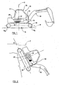
FIGURE 1 is an illustrative side view of a working machine for which the present invention may be employed; -
FIGURE 2 is a view similar tofigure 1 but showing the machine in an extreme attitude; -
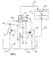
FIGURE 3 is a diagrammatic illustration including a fluid pumping apparatus in accordance with the present invention; -
FIGURE 4 is an exploded perspective view of an embodiment of the invention. - Referring to
figure 1 , aworking machine 10 which is for excavating in this example, is illustrated. Themachine 10 includes abody 12 with a groundengaging sub-structure 14 providing in this example, a pair oftracks 15 which are mechanically or hydrostatically driven viadrive wheels upper body superstructure 16 which is rotatable relative to thesub-structure 14 about a usually generally upright axis indicated at A. - The
superstructure 16 carries an operator'scab 17, and anexcavating arm 18, thearm 18 being pivoted at afront end 19 of theupper body superstructure 16. Theexcavating arm 18 is of conventional construction and further more detailed description is not required. - The
upper body superstructure 16 further mounts an assembly being aninternal combustion engine 20 which includes working components such aspistons 22 but other components too, which in use, require a supply of lubricant, such as oil. An oil pumping assembly is illustrated at 24, which includes apump housing 34 which may be integral with or connected to anengine housing 21 as will be described below. - In normal use, by which we mean that the
machine 10 is in the orientation shown infigure 1 , or at least has an attitude of less than about 35° to the horizontal in this example, (that is a reference plane P which passes through the centres ofdrive wheels engine 20, collects in asump 25 of theengine housing 21, and a pumping apparatus 24 ( seefigure 3 ) draws oil into amain oil inlet 26 in thesump 25, and delivers it to a pumpingapparatus outlet 27 which delivers the oil at pressure to one ormore galleries engine 20 from where the oil is distributed to thevarious working components 22. - However, in the event that the
machine 10 assumes an extreme attitude, as illustrated infigure 2 , in which the orientation of themachine 10 is such that the plane P is at 35° or greater to the horizontal, the oil in thesump 25 tends to pool in locations separated from themain oil inlet 26, and typically, as in the example in the drawings, the oil may pass into thepump housing 34 of thefluid pumping apparatus 24. In the absence of any means to continue to provide an oil supply to theworking components 22, it will be appreciated that starvation of lubricating oil available to thepumping apparatus 24, can damage theengine 20. - Although obviously the
machine 10 would not ordinarily be operated at the extreme attitude shown infigure 2 , it is a requirement for themachine 10 to be able to be continue to be so operated, because a skilled machine operator at least, may well be able to rescue themachine 10 from this extreme attitude, using thetracks 15 and theexcavating arm 18 for example. - In accordance with the present invention, a lubricant supply is established by the
oil pumping apparatus 24 which includes amain pump 30 which normally draws oil from a regular location in thesump 25 via themain inlet 26, and delivers it to thepumping apparatus outlet 27, and additionally anauxiliary pump 32 which may draw oil from an alternative location, into anauxiliary inlet 33, which is positioned where the oil may flow to, when themachine 10 assumes the extreme attitude shown infigure 2 and delivers it to the pumpingapparatus outlet 27. In this case, theauxiliary inlet 33 is positioned at an alternative location in thepump housing 34 so that theauxiliary pump 32 may draw the oil from the alternative location of the oilpumping assembly housing 34, and deliver it to thepumping apparatus outlet 27. - It will be appreciated that in the event that a supply of oil to pump is unavailable, it is undesirable for either the
main pump 30 or theauxiliary pump 32 to deliver air to the pumpingapparatus outlet 27, as this could seriously effect the efficiency of lubrication, and accordingly it is desirable in normal operation, for theauxiliary pump 32 to be isolated from thepumping apparatus outlet 27, and when theauxiliary pump 32 is operating to deliver the oil to thepumping apparatus outlet 27, for themain pump 30 to be isolated from thepumping apparatus outlet 27. According to the present invention, acontrol valve 40 provides this functionality. In any event, both the main 30 andauxiliary pumps 32 are in use simultaneously driven and are thus both immediately available to deliver oil to the pumpingapparatus outlet 27, depending upon availability of oil in thesump 25 in the case of themain pump 30, or in thepump housing 34 in the case of theauxiliary pump 32, and the condition of thecontrol valve 40. - Referring now also to
figure 4 , more details will become apparent. - The
sump 25 is in this example provided by abed plate 45 of theengine housing 21, the engine housing 21 further including anengine block 46 and a head (not shown). - The pump housing 34 of the
oil pumping apparatus 24 in this example, includes agear case 47, and apump body 48. - The engine housing 21 and the
pump housing 34 are in this example connected to each other but in an other example, could be integral. - The
main pump 30 is provided by a main pumping device, which in this example in which themain pump 30 is a gerotor type pump, includes nested hypocycloid inner andouter gear elements inner gear element 30a being carried on a drivenshaft 49 which extends through thepump body 48, theinner gear element 30a driving theouter gear element 30b. The inner andouter gear elements main pumping device 30 are received within a main pumping chamber of thepump body 48, whilst aninlet port 50 is provided by either one of thepump housing 34, a port plate, or as shown, anend wall 57 of thebed plate 45, theinlet port 50 being connected to themain pump inlet 26 to provide for oil to enter spaces between the meshing inner andouter gear elements - Since the
outer gear element 30b has one more tooth than theinner gear element 30a, one tooth volume is swept each rotation of the pumping device. As the inner andouter gear elements inlet port 50 side increase, to draw oil into the spaces between thegear elements inlet port 50. Simultaneously, at an opposite position, the spaces between the teeth of thegear elements oil pumping housing 34, a port plate, or as shown, anend wall 57 of thebed plate 45 of theengine housing 21. - The outlet port 51 communicates with
control valve 40 as will be explained. - The
auxiliary pump 32 is in the example, also a gerotor pump, aninner gear element 32a being carried on the drivenshaft 49, and the inner andouter gear elements auxiliary pumping chamber 56 of thepump body 48, at an opposite side of a separatingwall 58 to the main chamber of themain pumping device inlet port 60 for theauxiliary pump 32 is provided in aport plate 61 which closes theauxiliary pumping chamber 56 and provides a support for thedrive shaft 49, theinlet port 60 communicating with theauxiliary pump inlet 33 which in this example, is located in thegear case 47, whilst anoutlet port 61 is provided in the separatingwall 58 of thepump body 48, and communicates via a communicatingpassage 63 in thebed plate 45end wall 57, with thecontrol valve 40 as will be explained. - In another example, other species of main and
auxiliary pumps common drive shaft 49. In the present example, thedrive shaft 49 is mechanically driven via a drivengear 68 which is carried on thedrive shaft 49, the drivengear 68 being driven by adrive gear 69 which may in turn be driven from an engine crank, but in another example, one or both of the main andauxiliary pumps drive 69, and driven 68 gears, as well as thegear elements gear case 47 of thepump housing 34. - Examples of other suitable pumps are screw pumps, gear pumps, and impeller pumps.
- The
control valve 40 includes avalve member 71 and avalve chamber 72, thevalve chamber 72 in this example being provided in thebed plate 45 of theengine housing 21, and thevalve member 71 being movable axially within itschamber 72. - In normal use of the working
machine 10, when oil is available at the regular location in thesump 25 for pumping by themain pump 30, pressurised oil pumped through the outlet port 51 of themain pump 30 to amain pump outlet 30c, ensures that thevalve member 71 assumes a position in thevalve chamber 72 so that the pressurised oil is delivered to thepumping apparatus outlet 27, whilst theauxiliary pump 32 is isolated from thepumping apparatus outlet 27. An auxiliary relief device, namely avalve 75 is provided, so that any oil which may be pumped by theauxiliary pump 32, is mainly returned to thesump 25 via an auxiliary relief passage 76. Some such oil may pass to themain pump 30 via apassageway 77, for lubricating themain pump 30 in the event that a supply of oil is unavailable to themain pump 30, for example, when themachine 10 is in the extreme attitude shown infigure 2 . - A main relief device, i.e. a
valve 78, is provided, for returning any excess oil pumped by themain pump 30, mainly to thesump 25. As can be seen infigure 3 , some oil passes via apassageway 79 into thepump housing 34 to ensure that oil is always available to theauxiliary pump 32 so that it may immediately pump in the event that the oil supply for themain pump 30 becomes unavailable. Also, some of the excess oil passes via apassageway 80 to theauxiliary pump 32 to ensure lubrication of theauxiliary pump 32. - When the
machine 10 assumes an extreme attitude, as described above, oil may pool in thepump housing 24, and is thus available at the alternative location for pumping by theauxiliary pump 32. - Pressurised oil pumped through the outlet port of the
auxiliary pump 32 to anauxiliary pump outlet 32c, acts to move thevalve member 71 in itschamber 72, so that the pressurised oil from theauxiliary pump 32 is delivered to thepumping apparatus outlet 27, provided that there is not also an adequate supply of fluid being pumped by themain pump 30, in which case, themain pump 30 will take precedence. - For completeness, any oil which has been delivered to the
engine 20, after use, passes back into thesump 25 under gravity, as indicated by theline 82 inFigure 3 . - It can be seen from
figure 4 that the radial dimensions of the pumping devices of the main andauxiliary pumps gear elements auxiliary pump 32 are thinner than thegear elements main pump 30. Theauxiliary pump 32 is thus of smaller capacity than themain pump 30, but being thinner axially, presents less parasitic drag as thegear elements - This differential in pumping capacity also provides that that the
main pump 30 will always take precedence over theauxiliary pump 32, so that in the event of oil being available both to the main 30 and auxiliary 32 pumps, the pumped oil from themain pump 30 will preferentially be directed to the pumpedapparatus outlet 27, as the higher pressure produced by themain pump 30 will move thevalve member 71 in itschamber 72 accordingly. - Various modifications additional to those already mentioned may be made without departing from the scope of the present invention as defined in the claims.
- For example, although the specific example described relates to an oil or other lubricant pump for an assembly which is an
internal combustion engine 20 of a workingmachine 10, the invention may be applied for pumping other fluids in other assemblies as required. - The working
machine 10 may be a loading machine, such as a skid steer type loading machine having a loading arm rather than an excavatingarm 18, and the machine may have wheels instead of tracks 15.
Claims (12)
- A method of providing a supply of lubricant to working components (22) of an engine (20), the engine (20) including a reservoir (25) for lubricant to which the lubricant returns after use, under gravity, at least when the engine (20) is in a normal operating orientation, the method utilizing a pumping apparatus (24) including a pump housing (34) having main and auxiliary pumping chambers (56), a main pumping device (30a, 30b) which together with the main pumping chamber provides a main pump (30), and an auxiliary pumping device (32a, 32b) which together with the auxiliary pumping chamber provides an auxiliary pump (32), the main and auxiliary pumps (31, 32) being driven simultaneously, and the pumping apparatus (24) further including a main inlet (26) extending from a regular location in the lubricant reservoir (25) to the main pumping chamber and an auxiliary inlet (33) which extends from an alternative location to which lubricant may pass in the event that the engine is at an extreme attitude, to the auxiliary pumping chamber, characterised in that the pumping apparatus (24) comprises a control valve (40) including a valve member (71), and in that the method includes moving the valve member (71) between a first position in which lubricant pumped from the regular location by the main pump (30) is delivered to a pumping apparatus outlet (27) for supply to the working components (22) of the engine (20) when the engine (20) is in a normal operating orientation, and a second position in which lubricant pumped from the alternative location by the auxiliary pump (32) is delivered to the pumping apparatus outlet (27) when the engine (20) is at an extreme attitude.
- A method according to claim 1 wherein the control valve (40) includes a valve chamber (72) which communicates with a main pump outlet (30c) and an auxiliary pump outlet (32c), the method including moving the valve member (71) in the valve chamber (72) towards its first position when a pressurised lubricant supply is delivered to the main pump outlet any moving the moving the valve member (71) towards its second position when a pressurised lubricant supply is delivered to the auxiliary pumping apparatus outlet (32c).
- A method according to claim 2 which includes preferentially moving the valve member (71) towards its first position, so that in the event that a lubricant supply is delivered by both the main and auxiliary pumps (30, 32) to their respective outlets (30c, 32c), lubricant pumped by the main pump (30) is delivered to the pumping apparatus outlet (27).
- A method according to claim 3 wherein there is provided an auxiliary relief device (75) and the method includes relieving any lubricant which is pumped by the auxiliary pump (32) which is not required for use.
- A method according to any one of the preceding claims wherein there is provided a main relief device (78) and the method includes relieving excess pumped lubricant.
- A method according to any one of the preceding claims wherein the main and auxiliary pumps (30, 32) are gerotor pumps, the pumping devices including inner and outer nested hypocycloid gear elements (30a, 30b, 32a, 32b), the method including driving one of the gear elements (30a, 32a) to effect rotation of the other of the gear elements (30b, 32b).
- A method according to claim 6 wherein the auxiliary pump (32) is of lesser axial extent than the main pump (30), whilst the radial dimensions of the main and auxiliary pumps are about the same, and the method including driving both the main and auxiliary pumps (30, 32) by a common drive shaft (49).
- A method according to any one of the preceding claims which includes delivering least some of the lubricant pumped by the main pump (30) to a position to provide a supply of lubricant to the auxiliary inlet (33) for the auxiliary pump (32).
- In combination, an engine (20) which includes working components (22) which, in use, require a supply of lubricant, and a pumping apparatus (24), the engine (20) including a reservoir (25) for lubricant to which the lubricant returns after use, under gravity, at least when the engine (20) is in a normal operating orientation, the pumping apparatus (24) including a pump housing (34) having main and auxiliary pumping chambers (56), a main pumping device (30a, 30b) which together with the main pumping chamber provides a main pump (30), and an auxiliary pumping device (32a, 32b) which together with the auxiliary pumping chamber provides an auxiliary pump (32), the main and auxiliary pumps (30, 32) being driven simultaneously, and the apparatus (24) further including a main inlet (26) extending from a regular location in the lubricant reservoir (25) to the main pumping chamber and an auxiliary inlet, (33) which extends from an alternative location to which lubricant may pass in the event that the engine (20) assumes an extreme attitude, to the auxiliary pumping chamber, characterised in that the pumping apparatus (24) includes a control valve (40) including a valve member (71) which is moveable between a first position in which lubricant pumped from the regular location by the main pump (30) is delivered to a pumping apparatus outlet (27) for supply to the working components (22) of the engine (20), when the engine (20) is in a normal operating orientation and a second position in which lubricant pumped from the alternative location by the auxiliary pump (32), is delivered to the pumping apparatus outlet (27) when the engine (20) is at an extreme attitude.
- A working machine (10) having an engine (20) which includes working components (22) which, in use, require a supply of lubricant, and a pumping apparatus (24), the engine (20) including a reservoir (25) for lubricant, to which the lubricant returns after use, under gravity, at least when the engine (20) is in a normal operating orientation, the pumping apparatus (24) including a pump housing (34) having main and auxiliary pumping chambers (56), a main pumping device (30a, 30b) which together with the main pumping chamber provides a main pump (30), and an auxiliary pumping device (32a, 32b) which together with the auxiliary pumping chamber provides an auxiliary pump (32), the main and auxiliary pumps (30, 32) being driven simultaneously, and the apparatus (24) further including a main inlet (26) extending from a regular location in the lubricant reservoir (25) to the main pumping chamber and an auxiliary inlet (33) which extends from an alternative location to which lubricant may pass in the event that the engine (20) assumes an extreme attitude, to the auxiliary pumping chamber, characterised in that the pumping apparatus (24) includes a control valve (40) including a valve member (71) which is moveable between a first position in which lubricant pumped from the regular location by the main pump (30) is delivered to a pumping apparatus outlet (27) for supply to the working components (22) of the engine (20), when the engine (20) is in a normal operating orientation and a second position in which lubricant pumped from the alternative location by the auxiliary pump (32), is delivered to the pumping apparatus outlet (27) when the engine (20) is at an extreme attitude.
- A machine according to claim 10 wherein the engine includes a housing including a sump (25) which provides the reservoir for the lubricant, the pump housing (34) being integral or connected to the engine housing (46), and the regular location from where the main pump (30) draws lubricant, being in the sump (25), whilst the alternative location from where the auxiliary pump draws lubricant is in the pump housing (34).
- A machine according to claim 11 wherein the working machine (10) has a working arm (18) provided at a front end of the working machine (10), the lubricant pumping apparatus (24) being provided in a position such that in the event that the machine (10) adopts an extreme attitude when the front end of the machine (10) is below a rear end of the machine beyond a threshold amount, such that the lubricant flows out of the sump (25) into the pump housing (34), the auxiliary pump (32)delivers lubricant to lubricate the working components (22) of the engine (20).
Applications Claiming Priority (1)
| Application Number | Priority Date | Filing Date | Title |
|---|---|---|---|
| GBGB0515494.3A GB0515494D0 (en) | 2005-07-28 | 2005-07-28 | Fluid pumping apparatus |
Publications (3)
| Publication Number | Publication Date |
|---|---|
| EP1754868A2 EP1754868A2 (en) | 2007-02-21 |
| EP1754868A3 EP1754868A3 (en) | 2008-06-18 |
| EP1754868B1 true EP1754868B1 (en) | 2009-08-26 |
Family
ID=34976750
Family Applications (1)
| Application Number | Title | Priority Date | Filing Date |
|---|---|---|---|
| EP06013002A Active EP1754868B1 (en) | 2005-07-28 | 2006-06-23 | Providing lubricant to an engine |
Country Status (5)
| Country | Link |
|---|---|
| US (1) | US7516729B2 (en) |
| EP (1) | EP1754868B1 (en) |
| AT (1) | ATE441020T1 (en) |
| DE (1) | DE602006008707D1 (en) |
| GB (2) | GB0515494D0 (en) |
Families Citing this family (6)
| Publication number | Priority date | Publication date | Assignee | Title |
|---|---|---|---|---|
| GB0515494D0 (en) * | 2005-07-28 | 2005-08-31 | Bamford Excavators Ltd | Fluid pumping apparatus |
| GB2452493B (en) * | 2007-09-05 | 2012-05-23 | Bamford Excavators Ltd | Pumping apparatus |
| US9650925B2 (en) * | 2012-07-25 | 2017-05-16 | Cummins Intellectual Property, Inc. | System and method of augmenting low oil pressure in an internal combustion engine |
| US20140090930A1 (en) | 2012-09-28 | 2014-04-03 | United Technologies Corporation | Multiple reservoir lubrication system |
| CN110566291B (en) * | 2019-09-30 | 2022-04-12 | 兖矿国宏化工有限责任公司 | Turbine lubricating oil pump control system and control method |
| US11852232B1 (en) * | 2022-11-01 | 2023-12-26 | Textron Innovations Inc. | Persistent lubrication systems for aircraft gearboxes |
Family Cites Families (28)
| Publication number | Priority date | Publication date | Assignee | Title |
|---|---|---|---|---|
| US2373360A (en) * | 1943-10-29 | 1945-04-10 | Gulf Research Development Co | Apparatus for dry sump lubrication of engines |
| US2913069A (en) * | 1955-12-08 | 1959-11-17 | Maschf Augsburg Nuernberg Ag | Lubricating system for internal combustion engines |
| US3590953A (en) * | 1969-04-01 | 1971-07-06 | Caterpillar Tractor Co | Engine oil pan |
| DE2003740C3 (en) * | 1970-01-28 | 1981-05-07 | Robert Bosch Gmbh, 7000 Stuttgart | Hydraulic system with at least two pumps |
| US3800913A (en) * | 1972-08-04 | 1974-04-02 | Caterpillar Tractor Co | Recirculating oil system |
| DE2329328C2 (en) * | 1973-06-08 | 1985-03-28 | Zahnradfabrik Friedrichshafen Ag, 7990 Friedrichshafen | Automatic sequence valve |
| DE2344949C2 (en) * | 1973-09-06 | 1984-02-16 | Klöckner-Humboldt-Deutz AG, 5000 Köln | Lubricating device for internal combustion engines for a safe oil supply on large slopes |
| US4002027A (en) * | 1973-10-01 | 1977-01-11 | Tyrone Hydraulics, Inc. | Multiple pump control system |
| US4116577A (en) * | 1977-03-21 | 1978-09-26 | National Machine Company, Inc. | Flow sensing auxiliary pump by-pass valve |
| DE2731975C3 (en) * | 1977-07-15 | 1980-08-28 | Zahnradfabrik Friedrichshafen Ag, 7990 Friedrichshafen | Power steering for motor vehicles |
| DE2825578C2 (en) * | 1978-06-10 | 1984-01-26 | Zahnradfabrik Friedrichshafen Ag, 7990 Friedrichshafen | Automatic sequence valve for hydraulic systems |
| CA1196615A (en) | 1980-05-09 | 1985-11-12 | David E. Hanson | Gerotor vacuum pump |
| JPH0694805B2 (en) * | 1989-10-31 | 1994-11-24 | いすゞ自動車株式会社 | Engine lubricator |
| GB2286017A (en) | 1994-01-21 | 1995-08-02 | Concentric Pumps Ltd | Improvements relating to pumps |
| ATE171123T1 (en) * | 1994-07-08 | 1998-10-15 | Orenstein & Koppel Ag | METHOD FOR ACTUATING THE STEERING CYLINDERS OF MOBILE WORK MACHINERY AND STEERING SYSTEM FOR MOBILE WORK MACHINERY |
| JP3731961B2 (en) * | 1996-12-27 | 2006-01-05 | 株式会社小松製作所 | Bulldozer hydraulic system |
| US5918573A (en) | 1997-05-02 | 1999-07-06 | Killion; David L. | Energy efficient fluid pump |
| US5997372A (en) * | 1998-01-07 | 1999-12-07 | Brunswick Corporation | Marine propulsion device with an improved lubricant management system |
| US6234125B1 (en) * | 1998-03-30 | 2001-05-22 | Aft Atlas Fahrzeugtechnik Gmbh | Apparatus for angular adjustment of camshafts relative to crankshafts in combustion engines |
| US7086366B1 (en) * | 1999-04-20 | 2006-08-08 | Metaldyne Machining And Assembly Company, Inc. | Energy efficient fluid pump |
| US6386836B1 (en) | 2000-01-20 | 2002-05-14 | Eagle-Picher Industries, Inc. | Dual gerotor pump for use with automatic transmission |
| DE10014368B4 (en) * | 2000-03-23 | 2004-05-19 | Dr.Ing.H.C. F. Porsche Ag | Oil collecting device for an internal combustion engine |
| DE10034400A1 (en) * | 2000-07-14 | 2002-01-24 | Daimler Chrysler Ag | Dry sump lubricating system, for an automobile IC motor, has additional suction pump(s) to ensure oil can be extracted from different points at the oil bath at all vehicle angles |
| JP3865590B2 (en) * | 2001-02-19 | 2007-01-10 | 日立建機株式会社 | Hydraulic circuit for construction machinery |
| JP4446622B2 (en) * | 2001-03-27 | 2010-04-07 | トヨタ紡織株式会社 | Oil pump for internal combustion engine and method of using the same |
| JP2003166619A (en) * | 2001-11-30 | 2003-06-13 | Honda Motor Co Ltd | Internal combustion engine with torque converter |
| DE10159088A1 (en) * | 2001-12-01 | 2003-06-18 | Porsche Ag | Oil pump combination for an internal combustion engine |
| GB0515494D0 (en) * | 2005-07-28 | 2005-08-31 | Bamford Excavators Ltd | Fluid pumping apparatus |
-
2005
- 2005-07-28 GB GBGB0515494.3A patent/GB0515494D0/en not_active Ceased
-
2006
- 2006-06-22 GB GB0612382A patent/GB2428740B/en active Active
- 2006-06-23 EP EP06013002A patent/EP1754868B1/en active Active
- 2006-06-23 DE DE602006008707T patent/DE602006008707D1/en active Active
- 2006-06-23 AT AT06013002T patent/ATE441020T1/en not_active IP Right Cessation
- 2006-07-24 US US11/491,614 patent/US7516729B2/en not_active Expired - Fee Related
Also Published As
| Publication number | Publication date |
|---|---|
| DE602006008707D1 (en) | 2009-10-08 |
| EP1754868A3 (en) | 2008-06-18 |
| US7516729B2 (en) | 2009-04-14 |
| GB2428740B (en) | 2009-06-17 |
| GB2428740A (en) | 2007-02-07 |
| ATE441020T1 (en) | 2009-09-15 |
| GB0515494D0 (en) | 2005-08-31 |
| US20070039782A1 (en) | 2007-02-22 |
| GB0612382D0 (en) | 2006-08-02 |
| EP1754868A2 (en) | 2007-02-21 |
Similar Documents
| Publication | Publication Date | Title |
|---|---|---|
| EP1754868B1 (en) | Providing lubricant to an engine | |
| CA2972031A1 (en) | Reciprocating pump with dual circuit power end lubrication system | |
| US10670051B1 (en) | Hydraulic pump assembly | |
| EP1529958B1 (en) | Oil supply system for an IC engine | |
| USRE36807E (en) | Axle driving apparatus | |
| EP1561908A2 (en) | "Get Home" oil supply and scavenge system | |
| US8291702B2 (en) | Hydrostatic transmission | |
| US20070122298A1 (en) | Electrically driven pump unit | |
| US20090272596A1 (en) | Wheel end with integrated motor assembly | |
| US8215109B1 (en) | Dual pump apparatus with power take off | |
| US6991574B2 (en) | Dual level oil impeller for drive axle assembly | |
| JP7071419B2 (en) | Cooling lubrication system with drywall | |
| JP2007100317A (en) | Excavator | |
| US10487826B2 (en) | Integrated lubrication pump | |
| US11448212B2 (en) | Geared volumetric machine | |
| EP2594796B1 (en) | Bi-directional pump | |
| JP2005172019A (en) | Hydraulic mechanical transmission device | |
| CN101382135B (en) | Pumping device | |
| KR101219973B1 (en) | Lubricating device for differential device of commercial vehicle | |
| DE102016121239A1 (en) | System and method for hydraulically driving auxiliary equipment | |
| JP2009526172A (en) | Hydraulic transaxle for garden conservation vehicles | |
| EP2140141B1 (en) | Dual stage pump having intermittent mid-shaft load supports | |
| JP2023147585A (en) | Swash plate-type rotating machine | |
| EP1403531A1 (en) | Hydraulic pump circuit | |
| JP2009024731A (en) | Mission device |
Legal Events
| Date | Code | Title | Description |
|---|---|---|---|
| PUAI | Public reference made under article 153(3) epc to a published international application that has entered the european phase |
Free format text: ORIGINAL CODE: 0009012 |
|
| AK | Designated contracting states |
Kind code of ref document: A2 Designated state(s): AT BE BG CH CY CZ DE DK EE ES FI FR GB GR HU IE IS IT LI LT LU LV MC NL PL PT RO SE SI SK TR |
|
| AX | Request for extension of the european patent |
Extension state: AL BA HR MK YU |
|
| PUAL | Search report despatched |
Free format text: ORIGINAL CODE: 0009013 |
|
| AK | Designated contracting states |
Kind code of ref document: A3 Designated state(s): AT BE BG CH CY CZ DE DK EE ES FI FR GB GR HU IE IS IT LI LT LU LV MC NL PL PT RO SE SI SK TR |
|
| AX | Request for extension of the european patent |
Extension state: AL BA HR MK RS |
|
| 17P | Request for examination filed |
Effective date: 20081212 |
|
| GRAP | Despatch of communication of intention to grant a patent |
Free format text: ORIGINAL CODE: EPIDOSNIGR1 |
|
| AKX | Designation fees paid |
Designated state(s): AT BE BG CH CY CZ DE DK EE ES FI FR GB GR HU IE IS IT LI LT LU LV MC NL PL PT RO SE SI SK TR |
|
| GRAS | Grant fee paid |
Free format text: ORIGINAL CODE: EPIDOSNIGR3 |
|
| GRAA | (expected) grant |
Free format text: ORIGINAL CODE: 0009210 |
|
| AK | Designated contracting states |
Kind code of ref document: B1 Designated state(s): AT BE BG CH CY CZ DE DK EE ES FI FR GR HU IE IS IT LI LT LU LV MC NL PL PT RO SE SI SK TR |
|
| REG | Reference to a national code |
Ref country code: CH Ref legal event code: EP |
|
| REG | Reference to a national code |
Ref country code: IE Ref legal event code: FG4D |
|
| REF | Corresponds to: |
Ref document number: 602006008707 Country of ref document: DE Date of ref document: 20091008 Kind code of ref document: P |
|
| RBV | Designated contracting states (corrected) |
Designated state(s): AT BE BG CH CY CZ DE DK EE ES FI FR GB GR HU IE IS IT LI LT LU LV MC NL PL PT RO SE SI SK TR |
|
| REG | Reference to a national code |
Ref country code: GB Ref legal event code: FG4D |
|
| LTIE | Lt: invalidation of european patent or patent extension |
Effective date: 20090826 |
|
| PG25 | Lapsed in a contracting state [announced via postgrant information from national office to epo] |
Ref country code: IS Free format text: LAPSE BECAUSE OF FAILURE TO SUBMIT A TRANSLATION OF THE DESCRIPTION OR TO PAY THE FEE WITHIN THE PRESCRIBED TIME-LIMIT Effective date: 20091226 Ref country code: AT Free format text: LAPSE BECAUSE OF FAILURE TO SUBMIT A TRANSLATION OF THE DESCRIPTION OR TO PAY THE FEE WITHIN THE PRESCRIBED TIME-LIMIT Effective date: 20090826 Ref country code: FI Free format text: LAPSE BECAUSE OF FAILURE TO SUBMIT A TRANSLATION OF THE DESCRIPTION OR TO PAY THE FEE WITHIN THE PRESCRIBED TIME-LIMIT Effective date: 20090826 Ref country code: LT Free format text: LAPSE BECAUSE OF FAILURE TO SUBMIT A TRANSLATION OF THE DESCRIPTION OR TO PAY THE FEE WITHIN THE PRESCRIBED TIME-LIMIT Effective date: 20090826 Ref country code: SE Free format text: LAPSE BECAUSE OF FAILURE TO SUBMIT A TRANSLATION OF THE DESCRIPTION OR TO PAY THE FEE WITHIN THE PRESCRIBED TIME-LIMIT Effective date: 20090826 |
|
| NLV1 | Nl: lapsed or annulled due to failure to fulfill the requirements of art. 29p and 29m of the patents act | ||
| PG25 | Lapsed in a contracting state [announced via postgrant information from national office to epo] |
Ref country code: PL Free format text: LAPSE BECAUSE OF FAILURE TO SUBMIT A TRANSLATION OF THE DESCRIPTION OR TO PAY THE FEE WITHIN THE PRESCRIBED TIME-LIMIT Effective date: 20090826 Ref country code: NL Free format text: LAPSE BECAUSE OF FAILURE TO SUBMIT A TRANSLATION OF THE DESCRIPTION OR TO PAY THE FEE WITHIN THE PRESCRIBED TIME-LIMIT Effective date: 20090826 Ref country code: SI Free format text: LAPSE BECAUSE OF FAILURE TO SUBMIT A TRANSLATION OF THE DESCRIPTION OR TO PAY THE FEE WITHIN THE PRESCRIBED TIME-LIMIT Effective date: 20090826 Ref country code: LV Free format text: LAPSE BECAUSE OF FAILURE TO SUBMIT A TRANSLATION OF THE DESCRIPTION OR TO PAY THE FEE WITHIN THE PRESCRIBED TIME-LIMIT Effective date: 20090826 |
|
| PG25 | Lapsed in a contracting state [announced via postgrant information from national office to epo] |
Ref country code: CY Free format text: LAPSE BECAUSE OF FAILURE TO SUBMIT A TRANSLATION OF THE DESCRIPTION OR TO PAY THE FEE WITHIN THE PRESCRIBED TIME-LIMIT Effective date: 20090826 Ref country code: BG Free format text: LAPSE BECAUSE OF FAILURE TO SUBMIT A TRANSLATION OF THE DESCRIPTION OR TO PAY THE FEE WITHIN THE PRESCRIBED TIME-LIMIT Effective date: 20091126 Ref country code: PT Free format text: LAPSE BECAUSE OF FAILURE TO SUBMIT A TRANSLATION OF THE DESCRIPTION OR TO PAY THE FEE WITHIN THE PRESCRIBED TIME-LIMIT Effective date: 20091228 |
|
| PG25 | Lapsed in a contracting state [announced via postgrant information from national office to epo] |
Ref country code: CZ Free format text: LAPSE BECAUSE OF FAILURE TO SUBMIT A TRANSLATION OF THE DESCRIPTION OR TO PAY THE FEE WITHIN THE PRESCRIBED TIME-LIMIT Effective date: 20090826 Ref country code: DK Free format text: LAPSE BECAUSE OF FAILURE TO SUBMIT A TRANSLATION OF THE DESCRIPTION OR TO PAY THE FEE WITHIN THE PRESCRIBED TIME-LIMIT Effective date: 20090826 Ref country code: EE Free format text: LAPSE BECAUSE OF FAILURE TO SUBMIT A TRANSLATION OF THE DESCRIPTION OR TO PAY THE FEE WITHIN THE PRESCRIBED TIME-LIMIT Effective date: 20090826 Ref country code: RO Free format text: LAPSE BECAUSE OF FAILURE TO SUBMIT A TRANSLATION OF THE DESCRIPTION OR TO PAY THE FEE WITHIN THE PRESCRIBED TIME-LIMIT Effective date: 20090826 Ref country code: ES Free format text: LAPSE BECAUSE OF FAILURE TO SUBMIT A TRANSLATION OF THE DESCRIPTION OR TO PAY THE FEE WITHIN THE PRESCRIBED TIME-LIMIT Effective date: 20091207 |
|
| PG25 | Lapsed in a contracting state [announced via postgrant information from national office to epo] |
Ref country code: SK Free format text: LAPSE BECAUSE OF FAILURE TO SUBMIT A TRANSLATION OF THE DESCRIPTION OR TO PAY THE FEE WITHIN THE PRESCRIBED TIME-LIMIT Effective date: 20090826 |
|
| PG25 | Lapsed in a contracting state [announced via postgrant information from national office to epo] |
Ref country code: BE Free format text: LAPSE BECAUSE OF FAILURE TO SUBMIT A TRANSLATION OF THE DESCRIPTION OR TO PAY THE FEE WITHIN THE PRESCRIBED TIME-LIMIT Effective date: 20090826 |
|
| PLBE | No opposition filed within time limit |
Free format text: ORIGINAL CODE: 0009261 |
|
| STAA | Information on the status of an ep patent application or granted ep patent |
Free format text: STATUS: NO OPPOSITION FILED WITHIN TIME LIMIT |
|
| 26N | No opposition filed |
Effective date: 20100527 |
|
| PG25 | Lapsed in a contracting state [announced via postgrant information from national office to epo] |
Ref country code: GR Free format text: LAPSE BECAUSE OF FAILURE TO SUBMIT A TRANSLATION OF THE DESCRIPTION OR TO PAY THE FEE WITHIN THE PRESCRIBED TIME-LIMIT Effective date: 20091127 |
|
| PG25 | Lapsed in a contracting state [announced via postgrant information from national office to epo] |
Ref country code: MC Free format text: LAPSE BECAUSE OF NON-PAYMENT OF DUE FEES Effective date: 20100630 |
|
| REG | Reference to a national code |
Ref country code: CH Ref legal event code: PL |
|
| GBPC | Gb: european patent ceased through non-payment of renewal fee |
Effective date: 20100623 |
|
| PG25 | Lapsed in a contracting state [announced via postgrant information from national office to epo] |
Ref country code: IT Free format text: LAPSE BECAUSE OF FAILURE TO SUBMIT A TRANSLATION OF THE DESCRIPTION OR TO PAY THE FEE WITHIN THE PRESCRIBED TIME-LIMIT Effective date: 20090826 |
|
| PG25 | Lapsed in a contracting state [announced via postgrant information from national office to epo] |
Ref country code: LI Free format text: LAPSE BECAUSE OF NON-PAYMENT OF DUE FEES Effective date: 20100630 Ref country code: CH Free format text: LAPSE BECAUSE OF NON-PAYMENT OF DUE FEES Effective date: 20100630 Ref country code: IE Free format text: LAPSE BECAUSE OF NON-PAYMENT OF DUE FEES Effective date: 20100623 |
|
| PG25 | Lapsed in a contracting state [announced via postgrant information from national office to epo] |
Ref country code: GB Free format text: LAPSE BECAUSE OF NON-PAYMENT OF DUE FEES Effective date: 20100623 |
|
| PG25 | Lapsed in a contracting state [announced via postgrant information from national office to epo] |
Ref country code: LU Free format text: LAPSE BECAUSE OF NON-PAYMENT OF DUE FEES Effective date: 20100623 Ref country code: HU Free format text: LAPSE BECAUSE OF FAILURE TO SUBMIT A TRANSLATION OF THE DESCRIPTION OR TO PAY THE FEE WITHIN THE PRESCRIBED TIME-LIMIT Effective date: 20100227 |
|
| PG25 | Lapsed in a contracting state [announced via postgrant information from national office to epo] |
Ref country code: TR Free format text: LAPSE BECAUSE OF FAILURE TO SUBMIT A TRANSLATION OF THE DESCRIPTION OR TO PAY THE FEE WITHIN THE PRESCRIBED TIME-LIMIT Effective date: 20090826 |
|
| REG | Reference to a national code |
Ref country code: FR Ref legal event code: PLFP Year of fee payment: 11 |
|
| REG | Reference to a national code |
Ref country code: FR Ref legal event code: PLFP Year of fee payment: 12 |
|
| REG | Reference to a national code |
Ref country code: FR Ref legal event code: PLFP Year of fee payment: 13 |
|
| PGFP | Annual fee paid to national office [announced via postgrant information from national office to epo] |
Ref country code: DE Payment date: 20190619 Year of fee payment: 14 |
|
| REG | Reference to a national code |
Ref country code: DE Ref legal event code: R119 Ref document number: 602006008707 Country of ref document: DE |
|
| PG25 | Lapsed in a contracting state [announced via postgrant information from national office to epo] |
Ref country code: DE Free format text: LAPSE BECAUSE OF NON-PAYMENT OF DUE FEES Effective date: 20210101 |
|
| P01 | Opt-out of the competence of the unified patent court (upc) registered |
Effective date: 20230525 |
|
| PGFP | Annual fee paid to national office [announced via postgrant information from national office to epo] |
Ref country code: FR Payment date: 20230629 Year of fee payment: 18 |