EP2034127A2 - Extendable and retractable ladder - Google Patents
Extendable and retractable ladder Download PDFInfo
- Publication number
- EP2034127A2 EP2034127A2 EP08002727A EP08002727A EP2034127A2 EP 2034127 A2 EP2034127 A2 EP 2034127A2 EP 08002727 A EP08002727 A EP 08002727A EP 08002727 A EP08002727 A EP 08002727A EP 2034127 A2 EP2034127 A2 EP 2034127A2
- Authority
- EP
- European Patent Office
- Prior art keywords
- ladder
- disposed
- extendable
- retractable
- locking rods
- Prior art date
- Legal status (The legal status is an assumption and is not a legal conclusion. Google has not performed a legal analysis and makes no representation as to the accuracy of the status listed.)
- Granted
Links
- 238000009434 installation Methods 0.000 claims abstract description 3
- 230000000994 depressogenic effect Effects 0.000 claims description 13
- 238000010276 construction Methods 0.000 description 3
- 230000007257 malfunction Effects 0.000 description 2
Images





Classifications
-
- E—FIXED CONSTRUCTIONS
- E06—DOORS, WINDOWS, SHUTTERS, OR ROLLER BLINDS IN GENERAL; LADDERS
- E06C—LADDERS
- E06C1/00—Ladders in general
- E06C1/02—Ladders in general with rigid longitudinal member or members
- E06C1/04—Ladders for resting against objects, e.g. walls poles, trees
- E06C1/08—Ladders for resting against objects, e.g. walls poles, trees multi-part
- E06C1/12—Ladders for resting against objects, e.g. walls poles, trees multi-part extensible, e.g. telescopic
- E06C1/125—Ladders for resting against objects, e.g. walls poles, trees multi-part extensible, e.g. telescopic with tubular longitudinal members nested within each other
-
- E—FIXED CONSTRUCTIONS
- E06—DOORS, WINDOWS, SHUTTERS, OR ROLLER BLINDS IN GENERAL; LADDERS
- E06C—LADDERS
- E06C7/00—Component parts, supporting parts, or accessories
- E06C7/08—Special construction of longitudinal members, or rungs or other treads
- E06C7/082—Connections between rungs or treads and longitudinal members
- E06C7/083—Bracket type connection
-
- E—FIXED CONSTRUCTIONS
- E06—DOORS, WINDOWS, SHUTTERS, OR ROLLER BLINDS IN GENERAL; LADDERS
- E06C—LADDERS
- E06C7/00—Component parts, supporting parts, or accessories
- E06C7/08—Special construction of longitudinal members, or rungs or other treads
- E06C7/082—Connections between rungs or treads and longitudinal members
- E06C7/088—Connections between rungs or treads and longitudinal members with tie rods parallel to the rungs
-
- E—FIXED CONSTRUCTIONS
- E06—DOORS, WINDOWS, SHUTTERS, OR ROLLER BLINDS IN GENERAL; LADDERS
- E06C—LADDERS
- E06C7/00—Component parts, supporting parts, or accessories
- E06C7/42—Ladder feet; Supports therefor
-
- E—FIXED CONSTRUCTIONS
- E06—DOORS, WINDOWS, SHUTTERS, OR ROLLER BLINDS IN GENERAL; LADDERS
- E06C—LADDERS
- E06C7/00—Component parts, supporting parts, or accessories
- E06C7/42—Ladder feet; Supports therefor
- E06C7/46—Non-skid equipment
Definitions
- the present invention relates to a ladder and more particularly pertains to an extendable and retractable ladder which is adjustable in length and collapsible for storage.
- Ladders are often used in production and daily life.
- the length of conventional ladders is not adjustable and so it is very inconvenient to store and carry the ladders.
- Chinese patent CN2268119Y discloses an extendable and retractable ladder which is divided into three sections of vertical supports. The supports of each section are connected by a rung to form a ladder section. Each of the two ends of the rung is disposed with a spring and a fixing pin.
- the user moves the fixing pins at the two ends of the rung with his left and right hands respectively to sequentially unlock the supports of adjacent ladder sections.
- the upper ladder section is retracted into the lower ladder section with the help from an external force or other people.
- Extendable and retractable ladders of this kind of construction are inconvenient to use as the cooperation of a group of people is required for the extension or retraction of the ladders.
- the object of the present invention is to provide a new extendable and retractable ladder which can be extended and retracted by the control of one single hand and is safer to use.
- the present invention generally comprises a plurality of ladder sections, each of which is stackable upon and nestable within the adjacent ladder section.
- Each ladder section comprises two vertical pillars, one on a left side thereof and one on a right side thereof, and a rung connecting the vertical pillars.
- a locking means is disposed between adjacent ladder sections to lock relative installation positions of the ladder sections.
- the locking means is disposed in a middle portion of the rung of the ladder section and it comprises a left and a right locking rods which move in synchrony with each other, a spring which connects the left and the right locking rods, and a left and a right controlling handles which are connected to the left and the right locking rods respectively.
- Locking holes are disposed on adjacent ladder sections and free ends of the left and the right locking rods at corresponding positions.
- the rung is a H-shaped pipe with an inner tube disposed therein.
- the left and the right locking rods and the spring are disposed in the inner tube.
- the wall of the inner tube is disposed with elongated openings which allow the protrusion and horizontal movement of the corresponding controlling handles.
- the controlling handles are each disposed with a groove at opposing ends thereof.
- the grooves are each pivotally disposed with a movable clasp which is pivotable about a pivot axis for at least 90 degrees.
- the grooves are horizontally disposed and extend along the outer sides of the controlling handles.
- the movable clasps are L-shaped. One end of the L-shaped movable clasp is pivotally connected to the controlling handle and an other end thereof can fasten onto the outer side of the controlling handles after the movable clasp has rotated around the pivot axis for 90 degrees.
- the left and the right movable clasps are parallel to the rung, and the distance between the opposite ends of the left and the right movable clasps is zero or less than the distance of movement of the left and the right locking rods.
- the present invention To use the present invention, first rotate the two movable clasps until they are parallel to the rung and the ends of the movable clasps are opposite each other. As a result, the left and the right locking rods cannot move towards the centre by external force and the locking status of the ladder sections can be maintained.
- To retract the present invention rotate the movable clasps outwards to fasten them onto the controlling handles, at the same time move the left and the right controlling handles to sequentially retract the present invention. If the invention is an A-shaped ladder, the user can first unlock the ladder sections on the left and then retract the ladder sections on the left, then unlock the corresponding ladder sections on the right and then retract the ladder sections on the right.
- the bottom of the ladder legs of the present invention are each disposed with a pad.
- the pads are connected to the left and the right vertical pillars of the lowest ladder section of the ladder leg respectively by an angle adjusting means.
- the controlling part of the locking means of the present invention is disposed in a middle portion of the rung and connected by a spring, therefore only one single hand is required to simultaneously pull the left and the right controlling handles to unlock the ladder sections. This is more convenient in comparison with the conventional construction.
- the present invention is additionally disposed with a safety means (movable clasps) at the left and the right controlling handles.
- the movable clasps can prevent accidents caused by the retraction of the present invention due to accidental movement of the controlling handles or the malfunction of the spring, thereby increasing the safety of the present invention.
- the pads of the present invention are disposed with angle adjusting means. Therefore, when the present invention is used in an inclined position, its slip-proof pads remain in contact with the ground which greatly increases the stability and safety of using the present invention.
- this embodiment is an I-shaped extendable and retractable ladder which comprises six ladder sections, each of which is stackable upon and nestable within the adjacent ladder section.
- Each ladder section comprises a left and a right vertical pillars 11, 12 and a rung 4 connecting the left and the right vertical pillars 11, 12.
- a left ladder leg 1 is constituted by the left vertical pillars of all the six ladder sections, each of which is stackable upon and nestable within the adjacent left vertical pillar
- a right ladder leg 2 is constituted by the right vertical pillar of all the six ladder sections, each of which is stackable upon and nestable within the adjacent right vertical pillar.
- the rung 4 of each ladder section is disposed with a locking means 5 in a middle portion thereof for simultaneous locking of the adjacent vertical pillars 11, 11a on the left and the adjacent vertical pillars 21, 21a on the right.
- the rung 4 is a H-shaped pipe with an inner tube 41 disposed therein (as shown in FIG. 4 ).
- a left locking rod 51, a right locking rod 52 and a spring 53 are disposed in the inner tube 41 of the rung 4.
- the left locking rod 51 and the right locking rod 52 are connected by the spring 53 to each other at opposing ends thereof.
- the adjacent stackable and nestable left vertical pillars 11, 11a on the left are each disposed with a locking hole 111, 112.
- the locking holes 111, 112 overlap each other and the free end of the left locking rod 51 inserts into the locking holes 111, 112, thereby locking the relative positions of the left vertical pillars 11, 11a of the two adjacent ladder sections.
- the adjacent stackable and nestable vertical pillars 21, 21 a on the right of the extendable and retractable ladder are interlocked by the right locking rod 52 through the same means.
- the ends of the left and right locking rods 51, 52 which are connected to the spring 53 are each fixedly engaged with a L-shaped controlling handle 54, 55 by a screw (for the sake of easy operation, both the front and the rear sides of the rung 4 can be disposed with controlling handles, as shown in FIGS. 3 and 4 ).
- the wall of the inner tube 41 of the rung 4 is disposed with elongated openings 44, 45 (as shown in FIG. 3 ) so as to allow the screws connected with the controlling handles 54, 55 to penetrate the wall of the inner tube 41 to connect with the left locking rod 51 and the right locking rod 52 respectively.
- the inner tube 41 and the elongated openings 44, 45 confine the path and the distance of movement of the controlling handles 54, 55.
- the free ends of the left and the right locking rods 51, 52 are driven by the same spring 53 to simultaneously insert into the corresponding locking holes to lock the vertical pillars on the two sides, and the spring 53 and the controlling handles 54, 55 for controlling the left and the right locking rods 51, 52 are disposed in the middle portion of the rung 4
- user may use only one single hand to simultaneously control the two controlling handles 54, 55, thereby simultaneously moving the left locking rod 51 and the right locking rod 52 so as to allow smooth retraction of the extendable and retractable ladder.
- the two controlling handles 54, 55 are each disposed with a groove 56, 57 at opposing ends thereof.
- the grooves 56, 57 are horizontally disposed and extend along the outer sides of the controlling handles 54, 55.
- the grooves 56, 57 are each pivotally disposed with a movable clasp 58, 59 which is pivotable about a pivot axis for at least 90 degrees in a fixed direction.
- the movable clasp 58 is L-shaped. One end of the L-shaped movable clasp 58 functions as a rotational arm and is pivotally connected to the controlling handle 54. The end of the movable clasp 58 is curved.
- the other end of the movable clasp 58 can fasten onto the outer surface of the controlling handle 54.
- the left and the right locking rods 51, 52 insert into the corresponding locking holes, the left and the right movable clasps 58, 59 are parallel to the rung 4, and the distance between the opposite ends of the left and the right movable clasps 58, 59 is zero.
- the opposite ends of the left and the right movable clasps 58, 59 abut against each other to ensure that the controlling handles 54, 55 will not move accidentally.
- the movable clasps 58, 59 can prevent accidents caused by the retraction of the ladder due to accidental movement of the controlling handles 54, 55 or the malfunction of the spring 53.
- the bottom of the left ladder leg 1 and the right ladder leg 2 of the extendable and retractable ladder are each disposed with a pad 10.
- the pad 10 is connected to the vertical pillar 11b of the lowest ladder section of the ladder leg of the extendable and retractable ladder by an angle adjusting means.
- the angle adjusting means comprises a depressed sliding track 7 and a curved swinging piece 8 corresponding thereto which are pivotable relative to each other about a pin 6.
- the depressed sliding track 7 is affixed to the upper part of the pad 10 and the curved swinging piece 8 is affixed to the lower part of the vertical pillar 11 b.
- the depressed sliding track 7 is disposed with a mounting platform 71 in a middle portion thereof. Two sides of the mounting platform 71 are each disposed with an inwardly curved surface 72 parallel to each other.
- the mounting platform 71 is disposed with mounting holes 73 for receiving the pin 6.
- the curved swinging piece 8 is disposed with a cavity 81 in a middle portion thereof for receiving the mounting platform 71 of the depressed sliding track 7. Two sides of the curved swinging piece 8 are each disposed with a curved projection 82 which corresponds to the inwardly curved surfaces 72 of the depressed sliding track 7.
- the walls of the cavity 81 are also disposed with mounting holes 83 for receiving the pin 6.
- the depressed sliding track 7 and the curved swinging piece 8 are pivotable relative to each other about the pin 6, and the curved swinging piece 8 swings along the inwardly curved surfaces 72 of the depressed sliding track 7.
- a sleeve 9 is disposed between the vertical pillar 11 b and the curved swinging piece 8.
- the dimension of the sleeve 9 corresponds to that of the inner wall of the vertical pillar 11 b.
- Two sides of the sleeve 9 are respectively disposed with a recess 91.
- the wall of the recess 91 is disposed with a mounting hole 92.
- the head of the pin 6 which pivotally connects the depressed sliding track 7 and the depressed swinging piece 8 together with a fixing bolt cap 93 is received within the recess 91 to prevent any collision between the sleeve 9 and the vertical pillar 11b during assembly.
- the sleeve 9 is fixedly engaged with the vertical pillar 11b by screws or rivets.
- the rung 4 is engaged with the left and the right vertical pillars 11, 21 by fastening pieces 3 and fixed in position by fixing screws.
- One end of the fastening piece 3 is a C-shaped clamp 31 with an internal dimension corresponding to the dimension of the cross section of the left vertical pillar 11.
- the inner side of the C-shaped clamp 31 is disposed with a positioning circular platform 32 (as shown in FIG. 4 ), and a circular hole 113 is disposed on the upper part of the left vertical pillar 11 at a position corresponding to the positioning circular platform 32.
- the rung 4 and the left vertical pillar 11 are connected as a whole by fixing the opening of the C-shaped clamp 31 by means of fixing screws.
- the connection of other rungs and vertical pillars are likewise.
- the majority of the weight of the user standing on the rung 4 is transferred to the corresponding left vertical pillar 11 and right vertical pillar 21 by the fastening pieces 3 instead of focusing entirely on the left and the right locking rods 51, 52.
- the extendable and retractable ladder has a longer lifespan and is more durable.
Landscapes
- Engineering & Computer Science (AREA)
- Mechanical Engineering (AREA)
- Ladders (AREA)
Abstract
Description
- The present invention relates to a ladder and more particularly pertains to an extendable and retractable ladder which is adjustable in length and collapsible for storage.
- Ladders are often used in production and daily life. The length of conventional ladders is not adjustable and so it is very inconvenient to store and carry the ladders. Chinese patent
CN2268119Y discloses an extendable and retractable ladder which is divided into three sections of vertical supports. The supports of each section are connected by a rung to form a ladder section. Each of the two ends of the rung is disposed with a spring and a fixing pin. To retract the ladder, the user moves the fixing pins at the two ends of the rung with his left and right hands respectively to sequentially unlock the supports of adjacent ladder sections. Then, the upper ladder section is retracted into the lower ladder section with the help from an external force or other people. Extendable and retractable ladders of this kind of construction are inconvenient to use as the cooperation of a group of people is required for the extension or retraction of the ladders. - In view of the aforesaid disadvantages now present in the prior art, the object of the present invention is to provide a new extendable and retractable ladder which can be extended and retracted by the control of one single hand and is safer to use.
- To attain this, the present invention generally comprises a plurality of ladder sections, each of which is stackable upon and nestable within the adjacent ladder section. Each ladder section comprises two vertical pillars, one on a left side thereof and one on a right side thereof, and a rung connecting the vertical pillars. A locking means is disposed between adjacent ladder sections to lock relative installation positions of the ladder sections. The locking means is disposed in a middle portion of the rung of the ladder section and it comprises a left and a right locking rods which move in synchrony with each other, a spring which connects the left and the right locking rods, and a left and a right controlling handles which are connected to the left and the right locking rods respectively. Locking holes are disposed on adjacent ladder sections and free ends of the left and the right locking rods at corresponding positions.
- The rung is a H-shaped pipe with an inner tube disposed therein. The left and the right locking rods and the spring are disposed in the inner tube. The wall of the inner tube is disposed with elongated openings which allow the protrusion and horizontal movement of the corresponding controlling handles.
- The controlling handles are each disposed with a groove at opposing ends thereof. The grooves are each pivotally disposed with a movable clasp which is pivotable about a pivot axis for at least 90 degrees.
- The grooves are horizontally disposed and extend along the outer sides of the controlling handles.
- The movable clasps are L-shaped. One end of the L-shaped movable clasp is pivotally connected to the controlling handle and an other end thereof can fasten onto the outer side of the controlling handles after the movable clasp has rotated around the pivot axis for 90 degrees.
- When the left and the right locking rods insert into the corresponding locking holes, the left and the right movable clasps are parallel to the rung, and the distance between the opposite ends of the left and the right movable clasps is zero or less than the distance of movement of the left and the right locking rods.
- To use the present invention, first rotate the two movable clasps until they are parallel to the rung and the ends of the movable clasps are opposite each other. As a result, the left and the right locking rods cannot move towards the centre by external force and the locking status of the ladder sections can be maintained. To retract the present invention, rotate the movable clasps outwards to fasten them onto the controlling handles, at the same time move the left and the right controlling handles to sequentially retract the present invention. If the invention is an A-shaped ladder, the user can first unlock the ladder sections on the left and then retract the ladder sections on the left, then unlock the corresponding ladder sections on the right and then retract the ladder sections on the right.
- As an improvement for the present invention, the bottom of the ladder legs of the present invention are each disposed with a pad. The pads are connected to the left and the right vertical pillars of the lowest ladder section of the ladder leg respectively by an angle adjusting means.
- The present invention has the following advantages: the controlling part of the locking means of the present invention is disposed in a middle portion of the rung and connected by a spring, therefore only one single hand is required to simultaneously pull the left and the right controlling handles to unlock the ladder sections. This is more convenient in comparison with the conventional construction. More particularly, the present invention is additionally disposed with a safety means (movable clasps) at the left and the right controlling handles. The movable clasps can prevent accidents caused by the retraction of the present invention due to accidental movement of the controlling handles or the malfunction of the spring, thereby increasing the safety of the present invention. Moreover, the pads of the present invention are disposed with angle adjusting means. Therefore, when the present invention is used in an inclined position, its slip-proof pads remain in contact with the ground which greatly increases the stability and safety of using the present invention.
-
-
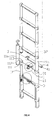
FIG. 1 is a front view of the extendable and retractable ladder of the present invention. -
FIG. 2 is a cross-sectional view along line A-A inFig. 1 . -
FIG. 3 is an enlarged view of the area B inFig. 2 . -
FIG. 4 is a perspective view ofFig. 1 -
FIG. 5 is an enlarged view of the area C inFig. 4 . -
FIG. 6 is an enlarged view of the area D inFig. 4 . -
FIG. 7 is a perspective view of the present invention as inFig. 4 after being retracted. -
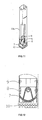
FIG. 8 is a top view ofFig. 7 -
FIG. 9 is an enlarged view of the area E inFig. 8 -
FIG. 10 is a perspective view showing the connection of the pad of the present invention with a vertical pillar. -
FIG. 11 is a perspective view ofFig. 10 with parts removed. -
FIG. 12 is a partial cross-sectional view ofFig. 10 . -
FIG. 13 is a partial cross-sectional view ofFig. 10 in an alternative direction. -
FIG. 14 is an axonometric view ofFig. 10 . - As illustrated in
FIGS. 1 to 9 , this embodiment is an I-shaped extendable and retractable ladder which comprises six ladder sections, each of which is stackable upon and nestable within the adjacent ladder section. Each ladder section comprises a left and a rightvertical pillars 11, 12 and arung 4 connecting the left and the rightvertical pillars 11, 12. Aleft ladder leg 1 is constituted by the left vertical pillars of all the six ladder sections, each of which is stackable upon and nestable within the adjacent left vertical pillar, and aright ladder leg 2 is constituted by the right vertical pillar of all the six ladder sections, each of which is stackable upon and nestable within the adjacent right vertical pillar. Therung 4 of each ladder section is disposed with a locking means 5 in a middle portion thereof for simultaneous locking of the adjacentvertical pillars 11, 11a on the left and the adjacentvertical pillars rung 4 is a H-shaped pipe with aninner tube 41 disposed therein (as shown inFIG. 4 ). Aleft locking rod 51, aright locking rod 52 and aspring 53 are disposed in theinner tube 41 of therung 4. Theleft locking rod 51 and theright locking rod 52 are connected by thespring 53 to each other at opposing ends thereof. The adjacent stackable and nestable leftvertical pillars 11, 11a on the left are each disposed with alocking hole locking holes left locking rod 51 inserts into thelocking holes vertical pillars 11, 11a of the two adjacent ladder sections. Similarly, the adjacent stackable and nestablevertical pillars right locking rod 52 through the same means. The ends of the left and right lockingrods spring 53 are each fixedly engaged with a L-shaped controllinghandle rung 4 can be disposed with controlling handles, as shown inFIGS. 3 and4 ). The wall of theinner tube 41 of therung 4 is disposed withelongated openings 44, 45 (as shown inFIG. 3 ) so as to allow the screws connected with the controlling handles 54, 55 to penetrate the wall of theinner tube 41 to connect with theleft locking rod 51 and theright locking rod 52 respectively. Theinner tube 41 and theelongated openings - The free ends of the left and the
right locking rods same spring 53 to simultaneously insert into the corresponding locking holes to lock the vertical pillars on the two sides, and thespring 53 and the controlling handles 54, 55 for controlling the left and theright locking rods rung 4 As a result, to retract the ladder, user may use only one single hand to simultaneously control the twocontrolling handles left locking rod 51 and theright locking rod 52 so as to allow smooth retraction of the extendable and retractable ladder. - This embodiment is further improved on the above basis. The two
controlling handles groove grooves grooves movable clasp movable clasp 58 is L-shaped. One end of the L-shapedmovable clasp 58 functions as a rotational arm and is pivotally connected to the controllinghandle 54. The end of themovable clasp 58 is curved. After themovable clasp 58 has rotated around the pivot axis for 90 degrees, the other end of themovable clasp 58 can fasten onto the outer surface of the controllinghandle 54. Moreover, when the left and theright locking rods movable clasps rung 4, and the distance between the opposite ends of the left and the rightmovable clasps right locking rods movable clasps movable clasps rung 4 respectively, the shorter ends of the L-shapedmovable clasps rung 4. The shape of the left and the rightmovable clasps spring 53. - This embodiment is further improved in another aspect. The bottom of the
left ladder leg 1 and theright ladder leg 2 of the extendable and retractable ladder are each disposed with apad 10. As illustrated inFIGS. 10 to 14 , thepad 10 is connected to thevertical pillar 11b of the lowest ladder section of the ladder leg of the extendable and retractable ladder by an angle adjusting means. The angle adjusting means comprises a depressed slidingtrack 7 and acurved swinging piece 8 corresponding thereto which are pivotable relative to each other about apin 6. The depressed slidingtrack 7 is affixed to the upper part of thepad 10 and thecurved swinging piece 8 is affixed to the lower part of thevertical pillar 11 b. The depressed slidingtrack 7 is disposed with a mountingplatform 71 in a middle portion thereof. Two sides of the mountingplatform 71 are each disposed with an inwardlycurved surface 72 parallel to each other. The mountingplatform 71 is disposed with mountingholes 73 for receiving thepin 6. Thecurved swinging piece 8 is disposed with a cavity 81 in a middle portion thereof for receiving the mountingplatform 71 of the depressed slidingtrack 7. Two sides of thecurved swinging piece 8 are each disposed with acurved projection 82 which corresponds to the inwardlycurved surfaces 72 of the depressed slidingtrack 7. The walls of the cavity 81 are also disposed with mounting holes 83 for receiving thepin 6. The depressed slidingtrack 7 and thecurved swinging piece 8 are pivotable relative to each other about thepin 6, and thecurved swinging piece 8 swings along the inwardlycurved surfaces 72 of the depressed slidingtrack 7. Asleeve 9 is disposed between thevertical pillar 11 b and thecurved swinging piece 8. The dimension of thesleeve 9 corresponds to that of the inner wall of thevertical pillar 11 b. Two sides of thesleeve 9 are respectively disposed with arecess 91. The wall of therecess 91 is disposed with a mountinghole 92. The head of thepin 6 which pivotally connects the depressed slidingtrack 7 and thedepressed swinging piece 8 together with a fixingbolt cap 93 is received within therecess 91 to prevent any collision between thesleeve 9 and thevertical pillar 11b during assembly. Thesleeve 9 is fixedly engaged with thevertical pillar 11b by screws or rivets. - In addition, as shown in
FIGS. 4 ,6 to 8 , therung 4 is engaged with the left and the rightvertical pillars fastening pieces 3 and fixed in position by fixing screws. One end of thefastening piece 3 is a C-shapedclamp 31 with an internal dimension corresponding to the dimension of the cross section of the leftvertical pillar 11. The inner side of the C-shapedclamp 31 is disposed with a positioning circular platform 32 (as shown inFIG. 4 ), and acircular hole 113 is disposed on the upper part of the leftvertical pillar 11 at a position corresponding to thepositioning circular platform 32. When thecircular platform 32 is engaged with thecircular hole 113, therung 4 and the leftvertical pillar 11 are connected as a whole by fixing the opening of the C-shapedclamp 31 by means of fixing screws. The connection of other rungs and vertical pillars are likewise. In this way, the majority of the weight of the user standing on therung 4 is transferred to the corresponding leftvertical pillar 11 and rightvertical pillar 21 by thefastening pieces 3 instead of focusing entirely on the left and theright locking rods - The above improvements in the construction of this embodiment can also be applied to extendable and retractable A-shaped ladder.
Claims (10)
- An extendable and retractable ladder which comprises a plurality of ladder sections, each of which is stackable upon and nestable within the adjacent ladder section; each ladder section comprises two vertical pillars (11, 21), one on a left side thereof and one on a right side thereof, and a rung (4) connecting the vertical pillars (11, 21); a locking means (5) is disposed between adjacent ladder sections to lock relative installation positions of the ladder sections, wherein the locking means (5) is disposed in a middle portion of the rung (4) of the ladder section and it comprises a left and a right locking rods (51, 52) which move in synchrony with each other, a spring (53) which connects the left and the right locking rods (51, 52), and a left and a right controlling handles (53, 54) which are connected to the left and the right locking rods (51, 52) respectively; locking holes are disposed on adjacent ladder sections and free ends of the left and the right locking rods (51, 52) at corresponding positions.
- The extendable and retractable ladder as in Claim 1, wherein the rung (4) is a H-shaped pipe with an inner tube (41) disposed therein; the left and the right locking rods (51, 52) and the spring (53) are disposed in the inner tube (41); the inner tube (41) has a wall disposed with elongated openings (44, 45) which allow protrusion and horizontal movement of the corresponding controlling handles (53, 54).
- The extendable and retractable ladder as in Claim 2, wherein the controlling handles (53, 54) are each disposed with a groove (56, 57) at opposing ends thereof; the grooves (56, 57) are each pivotally disposed with a movable clasp (58, 59) which is pivotable about a pivot axis for at least 90 degrees.
- The extendable and retractable ladder as in Claim wherein the grooves are horizontally disposed and extend along outer sides of the controlling handles.
- The extendable and retractable ladder as in Claim 4, wherein the movable clasps (58, 59) are L-shaped; one end of the L-shaped movable clasp is pivotally connected to the controlling handle and an other end thereof can fasten onto the outer side of the controlling handle after the movable clasp has rotated around the pivot axis for 90 degrees.
- The extendable and retractable ladder as in Claim 3, wherein when the left and the right locking rods insert into the corresponding locking holes, the left and the right movable clasps are parallel to the rung, and the distance between the opposite ends of the left and the right movable clasps is zero or less than the distance of movement of the left and the right locking rods.
- The extendable and retractable ladder as in any of the Claims 1 to 3, wherein the ladder legs of the present invention are each disposed with a pad at a bottom thereof; the pads are each connected to the left and the right vertical pillars of the lowest ladder section of the ladder leg by an angle adjusting means.
- The extendable and retractable ladder as in Claim 7, wherein the angle adjusting means comprises a depressed sliding track (7) and a curved swinging piece (8) corresponding thereto which are pivotable relative to each other about a pin (6); the depressed sliding track (7) is affixed to an upper part of the pad (10) and the curved swinging piece (8) is affixed to a lower part of the vertical pillar (11 b).
- The extendable and retractable ladder as in Claim 8, wherein a sleeve (9) is disposed between the vertical pillar (11 b) and the curved swinging piece (8); the pin (6) which pivotally connects the depressed sliding track (7) and the depressed swinging piece (8) is received within mounting holes disposed on the sleeve (9) and fixed on the sleeve (9); the sleeve (9) is received within the vertical pillar (11 b) and fixedly engaged with the vertical pillar (11 b) by fastening means.
- The extendable and retractable ladder as in Claim 7, wherein the extendable and retractable ladder is an I-shaped or A-shaped extendable and retractable ladder.
Applications Claiming Priority (1)
| Application Number | Priority Date | Filing Date | Title |
|---|---|---|---|
| CN200720056724.3U CN201116445Y (en) | 2007-09-07 | 2007-09-07 | Extension ladder |
Publications (3)
| Publication Number | Publication Date |
|---|---|
| EP2034127A2 true EP2034127A2 (en) | 2009-03-11 |
| EP2034127A3 EP2034127A3 (en) | 2012-10-10 |
| EP2034127B1 EP2034127B1 (en) | 2014-09-03 |
Family
ID=39967151
Family Applications (1)
| Application Number | Title | Priority Date | Filing Date |
|---|---|---|---|
| EP08002727.9A Not-in-force EP2034127B1 (en) | 2007-09-07 | 2008-02-14 | Extendable and retractable ladder |
Country Status (3)
| Country | Link |
|---|---|
| US (1) | US20090065304A1 (en) |
| EP (1) | EP2034127B1 (en) |
| CN (1) | CN201116445Y (en) |
Cited By (3)
| Publication number | Priority date | Publication date | Assignee | Title |
|---|---|---|---|---|
| IT201800002970A1 (en) * | 2018-02-23 | 2019-08-23 | F A C A L S R L | PORTABLE LADDER. |
| CN112392393A (en) * | 2020-11-13 | 2021-02-23 | 贵州电网有限责任公司 | Novel change special ladder of strain insulator pole insulator |
| CN115492515A (en) * | 2022-09-20 | 2022-12-20 | 重庆大学 | Device for outdoor evacuation of underground building space |
Families Citing this family (14)
| Publication number | Priority date | Publication date | Assignee | Title |
|---|---|---|---|---|
| US8225906B2 (en) | 2008-08-22 | 2012-07-24 | Core Distribution, Inc. | Extendable/retractable ladder |
| US8869939B2 (en) * | 2008-09-25 | 2014-10-28 | Ching Yao Kuo | Extension ladder |
| CN201448047U (en) * | 2009-07-09 | 2010-05-05 | 梁尧广 | Retractable ladder |
| US8056679B2 (en) * | 2009-08-11 | 2011-11-15 | Rong-Tai Hong | Retractable ladder |
| US10233692B2 (en) | 2014-12-02 | 2019-03-19 | Core Distribution, Inc. | Foldable ladder |
| CN106837155B (en) * | 2017-01-10 | 2018-08-07 | 潘跃进 | A kind of extension ladder |
| CN107512227B (en) * | 2017-08-11 | 2023-05-30 | 山西航天清华装备有限责任公司 | Sequential telescopic boarding ladder with adjustable length |
| CN107571898B (en) * | 2017-09-28 | 2023-08-25 | 广东顺和工业有限公司 | Instrument handcart |
| CN111448360B (en) * | 2017-11-08 | 2021-08-10 | 科尔分配股份有限公司 | Locking assembly for a telescopic ladder |
| US20190226217A1 (en) * | 2018-01-24 | 2019-07-25 | Tricam Industries, Inc. | Work platform |
| US11591855B2 (en) * | 2019-05-28 | 2023-02-28 | Frederick M. Pettit | In pool ladder assembly |
| US11795760B2 (en) * | 2019-10-24 | 2023-10-24 | Core Distribution, Inc. | Ladder tripod assembly and system |
| CN112550398B (en) * | 2020-12-05 | 2022-05-06 | 重庆工程职业技术学院 | Adjustable ladder stand structure and subway electric power tool car thereof |
| CN114457992B (en) * | 2022-01-05 | 2023-08-15 | 中铁天丰建筑工程有限公司 | a cantilevered scaffolding |
Citations (1)
| Publication number | Priority date | Publication date | Assignee | Title |
|---|---|---|---|---|
| CN2268119Y (en) | 1996-11-19 | 1997-11-19 | 郭劭民 | Telescopic ladder |
Family Cites Families (4)
| Publication number | Priority date | Publication date | Assignee | Title |
|---|---|---|---|---|
| US838275A (en) * | 1906-07-16 | 1906-12-11 | William A Rich | Ladder. |
| US3858684A (en) * | 1973-06-27 | 1975-01-07 | Harford E Goings | Telescoping ladder |
| WO1995023907A1 (en) * | 1994-03-01 | 1995-09-08 | Foxdale Developments Ltd. | Extensible ladder |
| JP3893503B2 (en) * | 1997-05-26 | 2007-03-14 | 長谷川工業株式会社 | Leg telescopic device |
-
2007
- 2007-09-07 CN CN200720056724.3U patent/CN201116445Y/en not_active Expired - Lifetime
-
2008
- 2008-01-02 US US11/968,634 patent/US20090065304A1/en not_active Abandoned
- 2008-02-14 EP EP08002727.9A patent/EP2034127B1/en not_active Not-in-force
Patent Citations (1)
| Publication number | Priority date | Publication date | Assignee | Title |
|---|---|---|---|---|
| CN2268119Y (en) | 1996-11-19 | 1997-11-19 | 郭劭民 | Telescopic ladder |
Cited By (4)
| Publication number | Priority date | Publication date | Assignee | Title |
|---|---|---|---|---|
| IT201800002970A1 (en) * | 2018-02-23 | 2019-08-23 | F A C A L S R L | PORTABLE LADDER. |
| CN112392393A (en) * | 2020-11-13 | 2021-02-23 | 贵州电网有限责任公司 | Novel change special ladder of strain insulator pole insulator |
| CN115492515A (en) * | 2022-09-20 | 2022-12-20 | 重庆大学 | Device for outdoor evacuation of underground building space |
| CN115492515B (en) * | 2022-09-20 | 2024-04-16 | 重庆大学 | A device for outdoor evacuation of underground building space |
Also Published As
| Publication number | Publication date |
|---|---|
| EP2034127B1 (en) | 2014-09-03 |
| CN201116445Y (en) | 2008-09-17 |
| US20090065304A1 (en) | 2009-03-12 |
| EP2034127A3 (en) | 2012-10-10 |
Similar Documents
| Publication | Publication Date | Title |
|---|---|---|
| EP2034127B1 (en) | Extendable and retractable ladder | |
| EP2998501B1 (en) | A telescopic ladder assembly | |
| US11746596B2 (en) | Adjustable ladders, ladder components and related methods | |
| US8844675B2 (en) | Portable ladder with a stand off device | |
| US12503914B2 (en) | Ladders and hinge for ladders | |
| EP3581754B1 (en) | Telescopic ladder assembly | |
| US7849967B2 (en) | Foldable stepladder with step lock | |
| US8066099B2 (en) | Retractable ladder | |
| US11578533B2 (en) | Step ladder device allowing the user to stand and work safely and comfortably on the upper steps of a step ladder | |
| US20230374858A1 (en) | Adjustable ladders, ladder components and related methods | |
| US12492596B2 (en) | Three section extension ladder | |
| US9151114B2 (en) | Telescopic ladder and locking mechanism thereof | |
| US20160263738A1 (en) | Hand drill lifting and actuating apparatus | |
| US20240183222A1 (en) | Reinforced spreader ladder step and ladder handle, ladders incorporating same, and related methods | |
| WO2012168684A1 (en) | Support apparatus and improved height access apparatus | |
| EP2378052A2 (en) | Folding stepladder | |
| JP4332884B2 (en) | stepladder | |
| JP2024053532A (en) | Telescopic leg device and ladder body | |
| US4244444A (en) | Walking stepladder | |
| RU119010U1 (en) | STAIRS | |
| NL2008496C2 (en) | A telescopic ladder assembly. | |
| ITMI20060769A1 (en) | REMOVABLE PROTECTION DEVICE FOR PIOLI STAIRS |
Legal Events
| Date | Code | Title | Description |
|---|---|---|---|
| PUAI | Public reference made under article 153(3) epc to a published international application that has entered the european phase |
Free format text: ORIGINAL CODE: 0009012 |
|
| AK | Designated contracting states |
Kind code of ref document: A2 Designated state(s): AT BE BG CH CY CZ DE DK EE ES FI FR GB GR HR HU IE IS IT LI LT LU LV MC MT NL NO PL PT RO SE SI SK TR |
|
| AX | Request for extension of the european patent |
Extension state: AL BA MK RS |
|
| PUAL | Search report despatched |
Free format text: ORIGINAL CODE: 0009013 |
|
| AK | Designated contracting states |
Kind code of ref document: A3 Designated state(s): AT BE BG CH CY CZ DE DK EE ES FI FR GB GR HR HU IE IS IT LI LT LU LV MC MT NL NO PL PT RO SE SI SK TR |
|
| AX | Request for extension of the european patent |
Extension state: AL BA MK RS |
|
| RIC1 | Information provided on ipc code assigned before grant |
Ipc: E06C 1/12 20060101AFI20120904BHEP Ipc: E06C 7/06 20060101ALI20120904BHEP |
|
| 17P | Request for examination filed |
Effective date: 20100615 |
|
| AKX | Designation fees paid |
Designated state(s): AT BE BG CH CY CZ DE DK EE ES FI FR GB GR HR HU IE IS IT LI LT LU LV MC MT NL NO PL PT RO SE SI SK TR |
|
| REG | Reference to a national code |
Ref country code: DE Ref legal event code: R079 Ref document number: 602008034162 Country of ref document: DE Free format text: PREVIOUS MAIN CLASS: E06C0001120000 Ipc: E06C0007080000 |
|
| GRAP | Despatch of communication of intention to grant a patent |
Free format text: ORIGINAL CODE: EPIDOSNIGR1 |
|
| RIC1 | Information provided on ipc code assigned before grant |
Ipc: E06C 1/12 20060101ALI20140306BHEP Ipc: E06C 7/08 20060101AFI20140306BHEP Ipc: E06C 7/42 20060101ALI20140306BHEP Ipc: E06C 7/46 20060101ALI20140306BHEP |
|
| INTG | Intention to grant announced |
Effective date: 20140317 |
|
| GRAS | Grant fee paid |
Free format text: ORIGINAL CODE: EPIDOSNIGR3 |
|
| GRAA | (expected) grant |
Free format text: ORIGINAL CODE: 0009210 |
|
| AK | Designated contracting states |
Kind code of ref document: B1 Designated state(s): AT BE BG CH CY CZ DE DK EE ES FI FR GB GR HR HU IE IS IT LI LT LU LV MC MT NL NO PL PT RO SE SI SK TR |
|
| REG | Reference to a national code |
Ref country code: GB Ref legal event code: FG4D |
|
| REG | Reference to a national code |
Ref country code: AT Ref legal event code: REF Ref document number: 685743 Country of ref document: AT Kind code of ref document: T Effective date: 20140915 Ref country code: CH Ref legal event code: EP |
|
| REG | Reference to a national code |
Ref country code: IE Ref legal event code: FG4D |
|
| REG | Reference to a national code |
Ref country code: DE Ref legal event code: R096 Ref document number: 602008034162 Country of ref document: DE Effective date: 20141016 |
|
| REG | Reference to a national code |
Ref country code: AT Ref legal event code: MK05 Ref document number: 685743 Country of ref document: AT Kind code of ref document: T Effective date: 20140903 |
|
| PG25 | Lapsed in a contracting state [announced via postgrant information from national office to epo] |
Ref country code: NO Free format text: LAPSE BECAUSE OF FAILURE TO SUBMIT A TRANSLATION OF THE DESCRIPTION OR TO PAY THE FEE WITHIN THE PRESCRIBED TIME-LIMIT Effective date: 20141203 Ref country code: GR Free format text: LAPSE BECAUSE OF FAILURE TO SUBMIT A TRANSLATION OF THE DESCRIPTION OR TO PAY THE FEE WITHIN THE PRESCRIBED TIME-LIMIT Effective date: 20141204 Ref country code: SE Free format text: LAPSE BECAUSE OF FAILURE TO SUBMIT A TRANSLATION OF THE DESCRIPTION OR TO PAY THE FEE WITHIN THE PRESCRIBED TIME-LIMIT Effective date: 20140903 Ref country code: ES Free format text: LAPSE BECAUSE OF FAILURE TO SUBMIT A TRANSLATION OF THE DESCRIPTION OR TO PAY THE FEE WITHIN THE PRESCRIBED TIME-LIMIT Effective date: 20140903 Ref country code: LT Free format text: LAPSE BECAUSE OF FAILURE TO SUBMIT A TRANSLATION OF THE DESCRIPTION OR TO PAY THE FEE WITHIN THE PRESCRIBED TIME-LIMIT Effective date: 20140903 Ref country code: FI Free format text: LAPSE BECAUSE OF FAILURE TO SUBMIT A TRANSLATION OF THE DESCRIPTION OR TO PAY THE FEE WITHIN THE PRESCRIBED TIME-LIMIT Effective date: 20140903 |
|
| REG | Reference to a national code |
Ref country code: NL Ref legal event code: VDEP Effective date: 20140903 |
|
| REG | Reference to a national code |
Ref country code: LT Ref legal event code: MG4D |
|
| PG25 | Lapsed in a contracting state [announced via postgrant information from national office to epo] |
Ref country code: AT Free format text: LAPSE BECAUSE OF FAILURE TO SUBMIT A TRANSLATION OF THE DESCRIPTION OR TO PAY THE FEE WITHIN THE PRESCRIBED TIME-LIMIT Effective date: 20140903 Ref country code: LV Free format text: LAPSE BECAUSE OF FAILURE TO SUBMIT A TRANSLATION OF THE DESCRIPTION OR TO PAY THE FEE WITHIN THE PRESCRIBED TIME-LIMIT Effective date: 20140903 Ref country code: HR Free format text: LAPSE BECAUSE OF FAILURE TO SUBMIT A TRANSLATION OF THE DESCRIPTION OR TO PAY THE FEE WITHIN THE PRESCRIBED TIME-LIMIT Effective date: 20140903 Ref country code: CY Free format text: LAPSE BECAUSE OF FAILURE TO SUBMIT A TRANSLATION OF THE DESCRIPTION OR TO PAY THE FEE WITHIN THE PRESCRIBED TIME-LIMIT Effective date: 20140903 |
|
| PG25 | Lapsed in a contracting state [announced via postgrant information from national office to epo] |
Ref country code: NL Free format text: LAPSE BECAUSE OF FAILURE TO SUBMIT A TRANSLATION OF THE DESCRIPTION OR TO PAY THE FEE WITHIN THE PRESCRIBED TIME-LIMIT Effective date: 20140903 |
|
| PG25 | Lapsed in a contracting state [announced via postgrant information from national office to epo] |
Ref country code: RO Free format text: LAPSE BECAUSE OF FAILURE TO SUBMIT A TRANSLATION OF THE DESCRIPTION OR TO PAY THE FEE WITHIN THE PRESCRIBED TIME-LIMIT Effective date: 20140903 Ref country code: PT Free format text: LAPSE BECAUSE OF FAILURE TO SUBMIT A TRANSLATION OF THE DESCRIPTION OR TO PAY THE FEE WITHIN THE PRESCRIBED TIME-LIMIT Effective date: 20150105 Ref country code: EE Free format text: LAPSE BECAUSE OF FAILURE TO SUBMIT A TRANSLATION OF THE DESCRIPTION OR TO PAY THE FEE WITHIN THE PRESCRIBED TIME-LIMIT Effective date: 20140903 Ref country code: CZ Free format text: LAPSE BECAUSE OF FAILURE TO SUBMIT A TRANSLATION OF THE DESCRIPTION OR TO PAY THE FEE WITHIN THE PRESCRIBED TIME-LIMIT Effective date: 20140903 Ref country code: SK Free format text: LAPSE BECAUSE OF FAILURE TO SUBMIT A TRANSLATION OF THE DESCRIPTION OR TO PAY THE FEE WITHIN THE PRESCRIBED TIME-LIMIT Effective date: 20140903 Ref country code: IS Free format text: LAPSE BECAUSE OF FAILURE TO SUBMIT A TRANSLATION OF THE DESCRIPTION OR TO PAY THE FEE WITHIN THE PRESCRIBED TIME-LIMIT Effective date: 20150103 |
|
| PG25 | Lapsed in a contracting state [announced via postgrant information from national office to epo] |
Ref country code: PL Free format text: LAPSE BECAUSE OF FAILURE TO SUBMIT A TRANSLATION OF THE DESCRIPTION OR TO PAY THE FEE WITHIN THE PRESCRIBED TIME-LIMIT Effective date: 20140903 |
|
| REG | Reference to a national code |
Ref country code: DE Ref legal event code: R097 Ref document number: 602008034162 Country of ref document: DE |
|
| PG25 | Lapsed in a contracting state [announced via postgrant information from national office to epo] |
Ref country code: BE Free format text: LAPSE BECAUSE OF NON-PAYMENT OF DUE FEES Effective date: 20150228 |
|
| PLBE | No opposition filed within time limit |
Free format text: ORIGINAL CODE: 0009261 |
|
| STAA | Information on the status of an ep patent application or granted ep patent |
Free format text: STATUS: NO OPPOSITION FILED WITHIN TIME LIMIT |
|
| PG25 | Lapsed in a contracting state [announced via postgrant information from national office to epo] |
Ref country code: DK Free format text: LAPSE BECAUSE OF FAILURE TO SUBMIT A TRANSLATION OF THE DESCRIPTION OR TO PAY THE FEE WITHIN THE PRESCRIBED TIME-LIMIT Effective date: 20140903 |
|
| 26N | No opposition filed |
Effective date: 20150604 |
|
| PG25 | Lapsed in a contracting state [announced via postgrant information from national office to epo] |
Ref country code: IT Free format text: LAPSE BECAUSE OF FAILURE TO SUBMIT A TRANSLATION OF THE DESCRIPTION OR TO PAY THE FEE WITHIN THE PRESCRIBED TIME-LIMIT Effective date: 20140903 |
|
| PG25 | Lapsed in a contracting state [announced via postgrant information from national office to epo] |
Ref country code: LU Free format text: LAPSE BECAUSE OF FAILURE TO SUBMIT A TRANSLATION OF THE DESCRIPTION OR TO PAY THE FEE WITHIN THE PRESCRIBED TIME-LIMIT Effective date: 20150214 |
|
| REG | Reference to a national code |
Ref country code: CH Ref legal event code: PL |
|
| PG25 | Lapsed in a contracting state [announced via postgrant information from national office to epo] |
Ref country code: MC Free format text: LAPSE BECAUSE OF FAILURE TO SUBMIT A TRANSLATION OF THE DESCRIPTION OR TO PAY THE FEE WITHIN THE PRESCRIBED TIME-LIMIT Effective date: 20140903 Ref country code: LI Free format text: LAPSE BECAUSE OF NON-PAYMENT OF DUE FEES Effective date: 20150228 Ref country code: CH Free format text: LAPSE BECAUSE OF NON-PAYMENT OF DUE FEES Effective date: 20150228 |
|
| REG | Reference to a national code |
Ref country code: IE Ref legal event code: MM4A |
|
| PG25 | Lapsed in a contracting state [announced via postgrant information from national office to epo] |
Ref country code: SI Free format text: LAPSE BECAUSE OF FAILURE TO SUBMIT A TRANSLATION OF THE DESCRIPTION OR TO PAY THE FEE WITHIN THE PRESCRIBED TIME-LIMIT Effective date: 20140903 |
|
| PG25 | Lapsed in a contracting state [announced via postgrant information from national office to epo] |
Ref country code: IE Free format text: LAPSE BECAUSE OF NON-PAYMENT OF DUE FEES Effective date: 20150214 |
|
| REG | Reference to a national code |
Ref country code: FR Ref legal event code: PLFP Year of fee payment: 9 |
|
| PG25 | Lapsed in a contracting state [announced via postgrant information from national office to epo] |
Ref country code: BE Free format text: LAPSE BECAUSE OF FAILURE TO SUBMIT A TRANSLATION OF THE DESCRIPTION OR TO PAY THE FEE WITHIN THE PRESCRIBED TIME-LIMIT Effective date: 20140903 |
|
| PG25 | Lapsed in a contracting state [announced via postgrant information from national office to epo] |
Ref country code: MT Free format text: LAPSE BECAUSE OF FAILURE TO SUBMIT A TRANSLATION OF THE DESCRIPTION OR TO PAY THE FEE WITHIN THE PRESCRIBED TIME-LIMIT Effective date: 20140903 |
|
| REG | Reference to a national code |
Ref country code: FR Ref legal event code: PLFP Year of fee payment: 10 |
|
| PG25 | Lapsed in a contracting state [announced via postgrant information from national office to epo] |
Ref country code: BG Free format text: LAPSE BECAUSE OF FAILURE TO SUBMIT A TRANSLATION OF THE DESCRIPTION OR TO PAY THE FEE WITHIN THE PRESCRIBED TIME-LIMIT Effective date: 20140903 Ref country code: HU Free format text: LAPSE BECAUSE OF FAILURE TO SUBMIT A TRANSLATION OF THE DESCRIPTION OR TO PAY THE FEE WITHIN THE PRESCRIBED TIME-LIMIT; INVALID AB INITIO Effective date: 20080214 |
|
| PG25 | Lapsed in a contracting state [announced via postgrant information from national office to epo] |
Ref country code: TR Free format text: LAPSE BECAUSE OF FAILURE TO SUBMIT A TRANSLATION OF THE DESCRIPTION OR TO PAY THE FEE WITHIN THE PRESCRIBED TIME-LIMIT Effective date: 20140903 |
|
| REG | Reference to a national code |
Ref country code: FR Ref legal event code: PLFP Year of fee payment: 11 |
|
| PGFP | Annual fee paid to national office [announced via postgrant information from national office to epo] |
Ref country code: DE Payment date: 20190219 Year of fee payment: 12 Ref country code: GB Payment date: 20190104 Year of fee payment: 12 |
|
| PGFP | Annual fee paid to national office [announced via postgrant information from national office to epo] |
Ref country code: FR Payment date: 20190220 Year of fee payment: 12 |
|
| REG | Reference to a national code |
Ref country code: DE Ref legal event code: R119 Ref document number: 602008034162 Country of ref document: DE |
|
| GBPC | Gb: european patent ceased through non-payment of renewal fee |
Effective date: 20200214 |
|
| PG25 | Lapsed in a contracting state [announced via postgrant information from national office to epo] |
Ref country code: GB Free format text: LAPSE BECAUSE OF NON-PAYMENT OF DUE FEES Effective date: 20200214 Ref country code: FR Free format text: LAPSE BECAUSE OF NON-PAYMENT OF DUE FEES Effective date: 20200229 Ref country code: DE Free format text: LAPSE BECAUSE OF NON-PAYMENT OF DUE FEES Effective date: 20200901 |