EP2034111A2 - Cylinder lock device - Google Patents
Cylinder lock device Download PDFInfo
- Publication number
- EP2034111A2 EP2034111A2 EP20080252708 EP08252708A EP2034111A2 EP 2034111 A2 EP2034111 A2 EP 2034111A2 EP 20080252708 EP20080252708 EP 20080252708 EP 08252708 A EP08252708 A EP 08252708A EP 2034111 A2 EP2034111 A2 EP 2034111A2
- Authority
- EP
- European Patent Office
- Prior art keywords
- inner cylinder
- cylinder
- rotation
- hole
- key
- Prior art date
- Legal status (The legal status is an assumption and is not a legal conclusion. Google has not performed a legal analysis and makes no representation as to the accuracy of the status listed.)
- Granted
Links
Images


Classifications
-
- E—FIXED CONSTRUCTIONS
- E05—LOCKS; KEYS; WINDOW OR DOOR FITTINGS; SAFES
- E05B—LOCKS; ACCESSORIES THEREFOR; HANDCUFFS
- E05B29/00—Cylinder locks and other locks with plate tumblers which are set by pushing the key in
- E05B29/0026—Cylinder locks and other locks with plate tumblers which are set by pushing the key in with longitudinally movable cylinder
-
- E—FIXED CONSTRUCTIONS
- E05—LOCKS; KEYS; WINDOW OR DOOR FITTINGS; SAFES
- E05B—LOCKS; ACCESSORIES THEREFOR; HANDCUFFS
- E05B9/00—Lock casings or latch-mechanism casings ; Fastening locks or fasteners or parts thereof to the wing
- E05B9/08—Fastening locks or fasteners or parts thereof, e.g. the casings of latch-bolt locks or cylinder locks to the wing
- E05B9/084—Fastening of lock cylinders, plugs or cores
- E05B9/086—Fastening of rotors, plugs or cores to an outer stator
-
- B—PERFORMING OPERATIONS; TRANSPORTING
- B60—VEHICLES IN GENERAL
- B60R—VEHICLES, VEHICLE FITTINGS, OR VEHICLE PARTS, NOT OTHERWISE PROVIDED FOR
- B60R21/00—Arrangements or fittings on vehicles for protecting or preventing injuries to occupants or pedestrians in case of accidents or other traffic risks
- B60R21/01—Electrical circuits for triggering passive safety arrangements, e.g. airbags, safety belt tighteners, in case of vehicle accidents or impending vehicle accidents
-
- E—FIXED CONSTRUCTIONS
- E05—LOCKS; KEYS; WINDOW OR DOOR FITTINGS; SAFES
- E05B—LOCKS; ACCESSORIES THEREFOR; HANDCUFFS
- E05B17/00—Accessories in connection with locks
- E05B17/14—Closures or guards for keyholes
- E05B17/18—Closures or guards for keyholes shaped as lids or slides
- E05B17/181—Closures or guards for keyholes shaped as lids or slides pivoting inwardly
-
- E—FIXED CONSTRUCTIONS
- E05—LOCKS; KEYS; WINDOW OR DOOR FITTINGS; SAFES
- E05B—LOCKS; ACCESSORIES THEREFOR; HANDCUFFS
- E05B9/00—Lock casings or latch-mechanism casings ; Fastening locks or fasteners or parts thereof to the wing
- E05B9/04—Casings of cylinder locks
- E05B2009/047—Means for returning cylinder locks to their neutral position
Definitions
- the present invention relates to a cylinder lock device in which an inner cylinder is rotated between first and second rotation positions by a key operation.
- a cylinder lock device in which an inner cylinder having a key insertion hole is inserted into a cylinder body rotatably between first and second rotation positions has been known in Japanese Patent Application Laid-Open No. 2002-106225 or the like.
- the inner cylinder is held in the first and second rotation positions.
- the inner cylinder is biased toward one of the first and second rotation positions by a return spring.
- the inner cylinder needs to be held and controlled in the other of the first and second rotation positions so as to prevent self return of the inner cylinder toward one of the first and second rotation positions by a spring force of the return spring.
- a structure of a cylinder lock device has been well known in which a tumbler is provided in an inner cylinder so as to slide between a protruding position where the tumbler protrudes from an outer periphery of the inner cylinder when a normal key is not inserted into a key insertion hole and a housed position where the tumbler is housed in the inner cylinder when the normal key is inserted, and it is supposed that the tumbler protruding from the outer periphery of the inner cylinder is abutted against and engaged with an inner periphery of a cylinder body to control the self return of the inner cylinder caused by the return spring.
- the tumbler protruding from the inner cylinder in the other of the first and second rotation positions is firmly abutted against the cylinder body by a spring force of the return spring, and thus when the normal key is inserted into the key insertion hole to house the tumbler in the inner cylinder, a large abutment friction force is applied between the tumbler and the cylinder body, which causes bad (heavy) feeling of insertion of the key into the key insertion hole.
- the tumbler protrudes from the inner cylinder only by the key being removed from the key insertion hole, and thus the position of the inner cylinder has to be held by the key until the key is removed in the other of the first and second rotation positions, which is inconvenient.
- the present invention is achieved in view of such circumstances, and has an object to provide a cylinder lock device in which an inner cylinder is biased toward one of first and second rotation positions by a return spring for a reliable locking/unlocking operation by a user, and that prevents bad feeling of insertion of a key and increases convenience.
- a cylinder lock device comprising: a cylinder body having a cylinder hole; an inner cylinder inserted into the cylinder hole rotatably between first and second rotation positions and axially movably between an advance position and a retracted position spaced apart from each other axially of the cylinder hole, and having a key insertion hole; a tumbler provided in the inner cylinder so as to slide along a plane perpendicular to an axis of the key insertion hole between a protruding position where the tumbler protrudes from an outer periphery of the inner cylinder when a normal key is not inserted into the key insertion hole and a housed position where the tumbler is housed in the inner cylinder when the normal key is inserted; a return spring that biases the inner cylinder to be rotated from the second rotation position to the first rotation position; biasing means for biasing the inner cylinder toward the advance position; an engaging member secured to the inner
- a movement preventing portion that is engaged with and abutted against the tumbler protruding from the outer periphery of the inner cylinder in the advance position in the second rotation position to prevent retraction of the inner cylinder from the advance position toward the retracted position may be provided on an inner periphery of the cylinder hole.
- An ON position in an embodiment corresponds to the first rotation position in the present invention
- an OFF position in the embodiment corresponds to the second rotation position in the present invention
- a push spring 34 corresponds to the biasing means in the present invention
- a second guide protrusion 39 in the embodiment corresponds to the movement preventing portion in the present invention.
- the guide and control means causes the inner cylinder to be retracted from the advance position to the retracted position against the biasing force of the biasing means, and advanced from the retracted position to the advance position by the biasing force of the biasing means in the second rotation position.
- the inner cylinder is held in the second rotation position by the guide and control means without being rotated toward the first rotation position against a spring force of the return spring.
- the tumbler provided slidably in the inner cylinder for determining whether the key inserted into the key insertion hole is the normal key is abutted against and engaged with the cylinder body in the protruding position to hold the second rotation position.
- the guide and control means provided between the engaging member secured to the inner cylinder and the cylinder body receives the spring force of the return spring, and the spring force of the return spring is not applied between the tumbler and the cylinder body. This prevents bad (heavy) feeling of insertion of the key into the key insertion hole.
- the inner cylinder is held in the second rotation position without the tumbler protruding from the inner cylinder, thus the position of the inner cylinder can be held whether the key is removed or not in the second rotation position, which increases convenience.
- the tumbler in the protruding position where the tumbler protrudes from the inner cylinder is abutted against and engaged with the movement preventing portion provided on the inner periphery of the cylinder hole, which prevents the inner cylinder from being retracted from the advance position to the retracted position and thus prevents the inner cylinder from being returned toward the first rotation position.
- the tumbler for determining whether the key inserted into the key insertion hole is the normal key is used as part of a configuration for preventing retraction of the inner cylinder in such a way, which avoids an increase in the number of components.
- a cylinder lock device 23 is mounted with a front end thereof facing a surface of the side lid 22.
- the front end of the cylinder lock device 23 is covered with a side door (not shown) on a passenger side of the vehicle by closing the side door.
- the cylinder lock device 23 includes a cylinder lock 25 that is rotatable between an ON position and an OFF position by a key 24 inserted therein, and a switch 26 for switching a switching mode according to a rotation operation of the cylinder lock 25.
- the switch 26 permits activation of a passenger side airbag (not shown) stored in a position corresponding to the passenger side of the instrument panel 21 with the cylinder lock 25 being in the ON position, and inhibits the activation of the passenger side airbag with the cylinder lock 25 being in the OFF position.
- the cylinder lock 25 includes: a cylinder body 28 having a cylinder hole 27; an inner cylinder 29 inserted into the cylinder hole 27 rotatably between the ON position and the OFF position and axially movably between an advance position and a retracted position spaced apart from each other axially of the cylinder hole 27, and having a key insertion hole 30; first and second tumblers 31 and 32 provided in the inner cylinder 29 so as to slide along a plane perpendicular to an axis of the key insertion hole 30; a return spring 33 that biases the inner cylinder 29 to be rotated from the OFF position to the ON position; a push spring 34 that biases the inner cylinder 29 toward the advance position; an engaging member 35 secured to the inner cylinder 29; and guide and control means 36 provided between the engaging member 35 and the cylinder body 28.
- the cylinder body 28 integrally includes a large diameter cylinder portion 28a and a small diameter cylinder portion 28b connected to a rear end of the large diameter cylinder portion 28a, and is made of a light alloy such as a zinc alloy.
- the cylinder hole 27 in the cylinder body 28 includes a large diameter hole 27a with an opened front end, a middle diameter hole 27b having a smaller diameter than the large diameter hole 27a and having a front end coaxially connected to a rear end of the large diameter hole 27a, and a small diameter hole 27c having a smaller diameter than the middle diameter hole 27b and coaxially connected to a rear end of the middle diameter hole 27b.
- the large diameter hole 27a and the middle diameter hole 27b are provided on the side of the large diameter cylinder portion 28a, the small diameter hole 27c is provided on the side of the small diameter cylinder portion 28b, and an annular step 27d facing forward is formed between the middle diameter hole 27b and the small diameter hole 27c.
- first guide protrusions 38 protruding radially inwardly from four points circumferentially regularly spaced apart from each other on an inner periphery of the large diameter hole 27a, connected flush with an inner periphery of the middle diameter hole 27b and axially extending
- second guide protrusions 39 protruding radially inwardly from the inner periphery of the large diameter hole 27a in the middles of the first guide protrusions 38, connected flush with the inner periphery of the middle diameter hole 27b and axially extending are integrally provided in a protruding manner.
- steps 27e placed respectively between the first and second guide protrusions 38 and 39 are formed to face forward. Further, front ends of the first guide protrusions 38 are positioned to be retracted from the position of the front end of the large diameter hole 27a, front ends of the second guide protrusions 39 are positioned to be retracted from the position of the front ends of the first guide protrusions 38, and a width of each first guide protrusion 38 circumferentially of the large diameter hole 27a is larger than a width of each second guide protrusion 39.
- the inner cylinder 29 integrally includes: a large diameter portion 29a having a larger diameter than the large diameter hole 27a of the cylinder hole 27 in the cylinder body 28 and placed forward of the cylinder body 28; a first middle diameter portion 29b that can fit in the large diameter hole 27a; a second middle diameter portion 29c that is slidably supported by inner peripheral surfaces of the first and second guide protrusions 38 and 39 in the cylinder body 28 and can fit in the middle diameter hole 27b of the cylinder hole 27; and a small diameter portion 29d that slidably fits in the small diameter hole 27c of the cylinder hole 27, and is made of a light alloy such as a zinc alloy.
- the key insertion hole 30 having a rectangular section extending along a diameter line of the cylinder hole 27 is provided so as to open in a front end of the inner cylinder 29, and the key 24 can be inserted into the key insertion hole 30 from the front end of the inner cylinder 29.
- the inner cylinder 29 is inserted into the cylinder hole 27 rotatably between the ON position and the OFF position, and axially movably between the advance position (the position in FIGS. 6 and 7 ) and the retracted position (the position in FIG. 8 ) spaced apart from each other axially of the cylinder hole 27.
- the advance position of the inner cylinder 29 as shown in FIGS. 6 and 7 , the first middle diameter portion 29b of the inner cylinder 29 is placed to be separated forward from the large diameter hole 27a of the cylinder hole 27, the second middle diameter portion 29c is placed to be supported by the inner peripheral surfaces of the first and second guide protrusions 38 and 39 forwards of the middle diameter hole 27b of the cylinder hole 27.
- the first middle diameter portion 29b is placed to fit in the large diameter hole 27a of the cylinder hole 27, and the second middle diameter portion 29c is placed to partly fit in the middle diameter hole 27b of the cylinder hole 27.
- a cover 46 having a rectangular opening 45 corresponding to the key insertion hole 30 is mounted so as to cover the front end of the inner cylinder 29.
- a shutter plate 47 that can cover the opening 45 from inside, a spindle 48 that rotatably supports the shutter plate 47, and a spring 49 that biases the shutter plate 47 so as to cover the opening 45 are housed, and the key 24 is inserted into the key insertion hole 30 so as to push open the shutter plate 47 with a tip thereof.
- the small diameter portion 29d of the inner cylinder 29 protrudes rearwardly from the cylinder body 28, and the engaging member 35 is secured to a protruding portion of the small diameter portion 29d from the cylinder body 28.
- the engaging member 35 integrally includes: a ring plate portion 35a coaxially surrounding the small diameter portion 29d; a fitting cylinder portion 35b coaxially connected to a radially intermediate portion of the ring plate portion 35a so as to fit the small diameter cylinder portion 28b of the cylinder body 28; engaging protrusions 35c and 35c protruding radially inwardly from two points circumferentially regularly spaced apart from each other on the ring plate portion 35a; and protrusions 35d and 35d protruding from two points circumferentially regularly spaced apart from each other on the ring plate portion 35a inwardly of the fitting cylinder portion 35b, and integrally connected to portions on an inner periphery of the fitting cylinder portion 35b closer to the ring plate portion 35a.
- the small diameter portion 29d of the inner cylinder 29 is fitted into the engaging member 35 so that the engaging protrusions 35c are engaged with the engaging recesses 40 until the protrusions 35d abut against the rear end of the small diameter cylinder portion 28b of the cylinder body 28, and an E type retaining ring 42 that engages the ring plate portion 35a of the engaging member 35 from the side opposite from the small diameter cylinder portion 28b of the cylinder body 28 is fitted to the annular recess 41.
- the engaging member 35 is mounted to the small diameter portion 29d of the inner cylinder 29 relatively nonrotatably and axially immovably, and secured to the small diameter portion 29d.
- the return spring 33 is of a coil shape surrounding the small diameter cylinder portion 28b of the cylinder body 28 and the fitting cylinder portion 35b of the engaging member 35, and one end of the return spring 33 is engaged with the small diameter cylinder portion 28b of the cylinder body 28.
- the small diameter cylinder portion 28b partly has a notch 43, and one end of the return spring 33 is engaged with one circumferential end of the notch 43.
- a lock protrusion 44 for preventing the return spring 33 from being easily removed from the notch 43 integrally protrudes on the cylinder body 28 so as to protrude from a rear portion of one circumferential end toward the other circumferential end of the notch 43.
- an engaging hole 50 with which the other end of the return spring 33 is engaged is provided in the ring plate portion 35a of the engaging member 35.
- the inner cylinder 29 is biased to return from the OFF position toward the ON position by the spring force exerted by the return spring 33.
- the guide and control means 36 is provided between the engaging member 35 secured to the inner cylinder 29 and the rear end of the cylinder body 28, and includes the protrusions 35d and 35d integrally provided on the engaging member 35, and cams 51 and 51 formed on the rear end of the small diameter cylinder portion 28b of the cylinder body 28 and against which the protrusions 35d and 35d are abutted.
- the inner cylinder 29 is biased toward the advance position by the push spring 34, and the protrusions 35d of the engaging member 35 secured to the inner cylinder 29 are biased to abut against the cams 51 formed on the cylinder body 28 placed forward of the engaging member 35.
- the cam 51 includes: an advance position side abutting surface 51a extending circumferentially of the cylinder body 28 and against which the protrusion 35d of the engaging member 35 it abutted with the inner cylinder 29 being in the advance position in the ON position; a retracted position side abutting surface 51b extending circumferentially of the cylinder body 28 and against which the protrusion 35d of the engaging member 35 is abutted immediately before the inner cylinder 29 reaches the OFF position in rotation of the inner cylinder 29 from the ON position to the OFF position; an inclined surface 51 c connecting between the advance position side abutting surface 51 a and the retracted position side abutting surface 51b so that the protrusion 35d is moved from the advance position side abutting surface 51a to the retracted position side abutting surface 51b against the biasing force of the push spring 34 with the rotation of the inner cylinder 29 from the ON position to the OFF position; and a control surface 51d connected perpendic
- the guide and control means 36 retracts the inner cylinder 29 from the advance position to the retracted position against the biasing force of the push spring 34 when the inner cylinder 29 is rotated from the ON position to the OFF position, advances the inner cylinder 29 from the retracted position to the advance position by the biasing force of the push spring 34 in the OFF position, and prevents the inner cylinder 29 advanced to the advance position in the OFF position from being rotated from the OFF position to the ON position.
- guide means 52 is provided for guiding the movement of the inner cylinder 29 from the advance position to the retracted position by the guide and control means 36 when the inner cylinder 29 is rotated from the ON position to the OFF position.
- the guide means 52 includes an arcuate guide surface 53 formed on the front end of the cylinder body 28 to face forward, and an abutting protrusion 29e provided in the front portion of the inner cylinder 29 so as to abut against the guide surface 53 from forward.
- the abutting protrusion 29e is integrally provided on the inner cylinder 29 so as to protrude radially outwardly from the first middle diameter portion 29b of the inner cylinder 29 to connect flush with an outer surface of the large diameter portion 29a of the inner cylinder 29.
- the guide surface 53 includes: an advance position side abutting surface 53a extending circumferentially of the cylinder body 28 and against which the abutting protrusion 29e is abutted with the inner cylinder 29 being in the advance position in the ON position; a retracted position side abutting surface 53b extending circumferentially of the cylinder body 28 and against which the abutting protrusion 29e is abutted with the inner cylinder 29 being rotated to the OFF position and in the retracted position; and an inclined surface 53c connecting between the advance position side abutting surface 53 a and the retracted position side abutting surface 53b and against which the abutting protrusion 29e is abutted when the inner cylinder 29 is moved from the advance position to the retracted position in the rotation from the ON position to the OFF position.
- the first tumbler 31 is provided in the second middle diameter portion 29c of the inner cylinder 29 slidably along the plane perpendicular to the axis of the key insertion hole 30, and between the inner cylinder 29 and the first tumbler 31, a spring 54 is provided that biases the first tumbler 31 so as to partly protrude from the outer surface of the second middle diameter portion 29c of the inner cylinder 29.
- the first tumbler 31 is housed in the second middle diameter portion 29c of the inner cylinder 29 against a spring force of the spring 54.
- the inner cylinder 29 is rotated 900 between the ON position and the OFF position, and in the ON position and the OFF position of the inner cylinder 29, the first tumbler 31 is in a circumferential position corresponding to two second guide protrusions 39 and 39 among the four second guide protrusions 39 provided on the inner periphery of the cylinder body 28.
- first tumbler 31 is placed forward of the second guide protrusions 39 with the inner cylinder 29 being in the advance position, and a protruding portion of the first tumbler 31 from the inner cylinder 29 faces one of the second guide protrusions 39 from forward with the inner cylinder 29 being in the advance position in the ON position and the OFF position and the first tumbler 31 partly protruding from the second middle diameter portion 29c of the inner cylinder 29 without the normal key 24 being inserted into the key insertion hole 30.
- the first tumbler 31 abuts against the second guide protrusions 39 to prevent retraction of the inner cylinder 29, and two of the four second guide protrusions 39 function as movement preventing portions that abut against the first tumbler 31 to prevent the retraction of the inner cylinder 29.
- the second tumbler 32 is provided in the second middle diameter portion 29c of the inner cylinder 29 behind the first tumbler 31 slidably along the plane perpendicular to the axis of the key insertion hole 30, and between the inner cylinder 29 and the second tumbler 32, a spring 55 is provided that biases the second tumbler 32 so as to partly protrude from the outer surface of the second middle diameter portion 29c of the inner cylinder 29.
- the second tumbler 32 is housed in the second middle diameter portion 29c of the inner cylinder 29 against a spring force of the spring 55.
- the second tumbler 32 In the ON position and the OFF position of the inner cylinder 29, the second tumbler 32 is in a circumferential position corresponding to two second guide protrusions 39 and 39 like the first tumbler 31. Further, in a protruding portion of the second tumbler 32 from the inner cylinder 29, an engaging recess 56 with which the second guide protrusion 39 is engaged is provided, and the engaging recess 56 in the protruding portion of the second tumbler 32 from the inner cylinder 29 is placed to partly house the second guide protrusion 39 with the inner cylinder 29 being in the advance position in the ON position and the OFF position and the second tumbler 32 partly protruding from the second middle diameter portion 29c of the inner cylinder 29 without the normal key 24 being inserted into the key insertion hole 30.
- the rotation of the inner cylinder 29 toward the ON position by the return spring 33 is controlled by the protrusions 35d of the guide and control means 36 abutting against the control surfaces 51d.
- the first and second tumblers 31 and 32 protruding from the inner cylinder 29 without the normal key 24 being inserted into the key insertion hole 30 do not abut against and engage with the second guide protrusion 39, thereby preventing the biasing force by the return spring 33 from being applied between the first and second tumblers 31 and 32 and the cylinder body 28.
- the switch 26 comprises a switch case 60 made of synthetic resin and fixedly placed behind the cylinder body 28, and a switch mechanism 61 housed in the switch case 60.
- the switch case 60 includes a first case member 62 made of synthetic resin and formed into a bowl shape opening rearwardly, and a second case member 63 having a cylinder portion 63a with a tip portion fitting in a rear opening end of the first case member 62, connected to each other, and a coupler 63b is formed integrally with the second case member 63.
- the switch mechanism 61 includes: a ring plate shaped contact support portion 64 formed integrally with the second case member 63; a disk shaped rotation member 65 made of synthetic resin and facing the contact support portion 64 from forward; a connecting shaft 66 made of synthetic resin and which rotatably passes through a through hole 67 provided in the middle portion of the first case member 62 and has a rear portion rotatably supported by the second case member 63; a plurality of fixed contacts (not shown) provided on the contact support portion 64; and a plurality of movable contacts 69 provided on the rotation member 65 so as to switch conduction and interruption of the fixed contacts according to rotation of the rotation member 65.
- the connecting shaft 66 is relatively nonrotatably connected to the rotation member 65, and in this embodiment, the connecting shaft 66 and the rotation member 65 are integrally formed.
- a front end of the connecting shaft 66 is relatively nonrotatably fitted in a connecting recess 70 provided in the rear end of the inner cylinder 29 and thus connected to the inner cylinder 29, and the connecting shaft 66 and the rotation member 65 rotate with rotation of the inner cylinder 29.
- the push spring 34 is made of conductive metal and formed into a coil shape.
- the push spring 34 is provided in a compressed manner between a spring receiving member 71 secured to the rear end of the inner cylinder 29, and the first case member 62 of the switch case 60 connected to the cylinder body 28 and thus fixedly placed behind the cylinder body 28.
- the spring receiving member 71 is made of nonconductive material and integrally includes: an inner cylinder portion 71a in which the small diameter portion 29d that is the rear end of the inner cylinder 29 is fitted; an annular abutting portion 71b overhanging radially inwardly from the inner cylinder portion 71a so as to abut against the rear end surface of the inner cylinder 29; a flange 71 c overhanging radially outwardly from the inner cylinder portion 7 1 a; and an outer cylinder portion 71d connected to an outer periphery of the flange 71 c and extending toward the switch case 60. Between the first case member 62 of the switch case 60 and the flange 71 c, the push spring 34 is provided so as to surround the inner cylinder portion 71 a.
- the spring receiving member 71 is biased by the push spring 34 so that the abutting portion 71b abuts against the rear end surface of the inner cylinder 29.
- the push spring 34 is provided between the spring receiving member 71 in which the rear end of the inner cylinder 29 is fitted, and the first case member 62 of the switch case 60 fixedly placed behind the cylinder body 28, and thus the spring receiving member 71 is substantially secured to the rear end of the inner cylinder 29.
- the cylinder lock 25 and the switch 26 are connected via a housing 73 made of synthetic resin.
- the housing 73 is made of synthetic resin and formed into a closed-end cylindrical shape so that one end of a cylinder portion 73b is integrally connected to an end wall 73a having an opening 74 communicating with the front end of the key insertion hole 30, and the end wall 73a is formed into a ring shape so that an outer periphery thereof overhangs radially outwardly more than the outer periphery of the cylinder portion 73b.
- the cylinder body 28 of the cylinder lock 25 is fitted in one end of the housing 73.
- a seal member 76 having an opening 75 that provides communication between the opening 45 and the opening 74 in the end wall 73a is bonded, and the seal member 76 is brought into contact with an inner surface of the end wall 73a when the inner cylinder 29 is in the advance position.
- the ON position (ON) and the OFF position (OFF) for indicating rotation positions of the inner cylinder 29, that is, the positions of the key insertion hole 30 and the openings 45 and 75 are displayed.
- slits 77 and 77 axially extending in a plurality of, for example, two circumferential points on the housing 73 so as to be closed at one ends and opened at the other ends in the other end of the housing 73, that is, the other end of the cylinder portion 73b, a plurality of, for example, two first engaging holes 79 and 79 placed between one ends of the slits 77 and the end wall 73a and with which first engaging protrusions 78 and 78 integrally protruding on a plurality of, for example, two points on the outer periphery of the cylinder body 28 fitted in one end of the housing 73 are resiliently engaged respectively, and a plurality of, for example, four second engaging holes 81 placed in the other end of the cylinder portion 73b between the slits 77 and with which a plurality of, for example, four second engaging protrusions 80 integrally protruding on the outer periphery of
- the second case member 63 that constitutes part of the switch case 60, a plurality of, for example, two opening preventing portions 82 and 82 are provided that abut from outside against an outer surface on the other end side of the housing 73, that is, the other end side of the cylinder portion 73b between the slits 77 according to the switch case 60 at least partly (in this embodiment, partly) fitting in the other end of the housing 73.
- the cylinder body 28 is fitted in one end of the housing 73 from the other end of the housing 73, and secured to the housing 73 by the first engaging protrusions 78 on the cylinder body 28 being resiliently engaged with the first engaging holes 79 in the housing 73.
- the switch case 60 partly fitted in the other end of the housing 73 is secured to the housing 73 by the second engaging protrusions 80 being resiliently engaged with the second engaging holes 81 on the other end side of the housing 73.
- a mounting cylinder portion 83 passing through an opening 84 provided in the right end wall 21a of the instrument panel 21 and extending inwardly of the instrument panel 21 is provided integrally with the side lid 22.
- the cylinder lock device 23 is inserted into the mounting cylinder portion 83 so that an outer peripheral portion of the end wall 73a at the front end of the cylinder lock device 23 engages a peripheral edge at an outer end of the mounting cylinder portion 83.
- base ends of engaging arm portions 85 and 85 extending forward are integrally connected to the outer periphery of the cylinder portion 73b in the middle of the slits 77 and 77 in an axially intermediate portion of the housing 73, and tips of the arm portions 85 that are brought into slide contact with an inner surface of the mounting cylinder portion 83 and bent radially inwardly in insertion of the cylinder lock device 23 into the mounting cylinder portion 83 resiliently engage an inner end of the mounting cylinder portion 83 according to the insertion of the cylinder lock device 23 until the outer peripheral portion of the end wall 73a engages the peripheral edge at the outer end of the mounting cylinder portion 83, and thus the cylinder lock device 23 is mounted to the side lid 22.
- the inner cylinder 29 having the key insertion hole 30 is inserted into the cylinder hole 27 rotatably between the ON position and the OFF position and axially movably between the advance position and the retracted position spaced apart from each other axially of the cylinder hole 27 in the cylinder body 28, and rotationally biased toward the ON position by the spring force of the return spring 33 and biased toward the advance position by the push spring 34.
- the guide and control means 36 provided between the engaging member 35 secured to the inner cylinder 29 and the cylinder body 28 retracts the inner cylinder 29 from the advance position to the retracted position against the biasing force of the push spring 34 when the inner cylinder 29 is rotated from the ON position to the OFF position by the normal key 24 inserted into the key insertion hole 30, advances the inner cylinder 29 from the retracted position to the advance position by the biasing force of the push spring 34 in the OFF position, and prevents the inner cylinder 29 in the advance position in the OFF position from being rotated from the OFF position to the ON position.
- the normal key 24 is inserted into the key insertion hole 30 to rotate the inner cylinder 29 from the ON position to the OFF position, and then the guide and control means 36 causes the inner cylinder 29 to be held in the OFF position against the spring force of the return spring 36 without being rotated toward the ON position, in the advance position in the OFF position.
- the first and second tumblers 31 and 32 provided slidably in the inner cylinder 29 so as to protrude from the outer periphery of the inner cylinder 29 when the normal key 24 is not inserted into the key insertion hole 30 for determining whether the key 24 inserted into the key insertion hole 30 is the normal key 24 are abutted against and engaged with the cylinder body 28 in the protruding position to hold the OFF position of the inner cylinder 29, and the guide and control means 36 provided between the engaging member 35 secured to the inner cylinder 29 and the cylinder body 28 receives the spring force of the return spring 33.
- the spring force of the return spring 33 is not applied between the first and second tumblers 31 and 32 and the cylinder body 28. This prevents bad (heavy) feeling of insertion of the key 24 into the key insertion hole 30.
- the inner cylinder 29 is held in the OFF position without the first and second tumblers 31 and 32 protruding from the inner cylinder 29, thus the inner cylinder 29 can be held in the OFF position whether the key 24 is removed or not in the OFF position, which increases convenience.
- the first tumbler 31 protruding from the outer periphery of the inner cylinder 29 in the OFF position is engaged with and abutted against one of the four second guide protrusions 39 provided on the inner periphery of the cylinder hole 27 in the cylinder body 28 to prevent retraction of the inner cylinder 29 from the advance position to the retracted position.
- the inner cylinder 29 cannot be retracted from the advance position to the retracted position, and thus the inner cylinder 29 is not returned toward the ON position.
- the first tumbler 31 for determining whether the key 24 inserted into the key insertion hole 30 is the normal key 24 is used as part of a configuration for preventing retraction of the inner cylinder 29, which prevents an increase in the number of components.
- the cylinder lock 25 including the cylinder body 28 and the inner cylinder 29 inserted into the cylinder hole 27 in the cylinder body 28, and the switch 26 comprising the switch case 60 placed behind the cylinder body 28 and the switch mechanism 61 housed in the switch case 60 and interlocked with and connected to the inner cylinder 29 are connected via the housing 63.
- the housing 73 made of synthetic resin, formed into a closed-end cylindrical shape and having the end wall 73a at one end, there are provided the plurality of first engaging holes 79 with which the first engaging protrusions 78 integrally protruding on the plurality of points on the outer periphery of the cylinder body 28 fitted in one end of the housing 73 are resiliently engaged respectively, and the plurality of second engaging holes 81 with which the plurality of second engaging protrusions 80 integrally protruding on the outer periphery of the second case member 63 that constitutes part of the switch case 60 at least partly fitted in the other end of the housing 73 are resiliently engaged respectively.
- the cylinder body 28 fitted in one end of the housing 73 is secured to the housing 73, and the switch case 60 at least partly fitted in the other end of the housing 73 is secured to the other end of the housing 73, thereby increasing connection rigidity between the switch case 60 and the cylinder body 28.
- the slits 77 axially extending in the plurality of circumferential points on the housing 73 so as to be closed at one ends and opened at the other ends into the other end of the housing 73 are provided, and the first engaging holes 79 are placed between one ends of the slits 77 and the end wall 73a, and thus the first engaging protrusions 78 are brought into contact with the inner surface of the housing 73 only in a short range, at the one ends of the slits 77 and the first engaging holes 79, when the cylinder body 28 is fitted in the housing 73 from the other end side.
- the plurality of second engaging holes 81 with which the second engaging protrusions 80 on the outer periphery of the switch case 60 are resiliently engaged respectively are placed in the other end of the housing 73 between the slits 77, and thus the second engaging protrusions 80 are also brought into contact with the inner surface of the housing 73 only in a short range when the switch case 60 is at least partly fitted in the other end of the housing 73.
- the first engaging protrusions 78 and the second engaging protrusions 80 are brought into contact with the inner surface of the housing 73 in a short distance to improve an assemblability.
- the plurality of slits 77 are provided, thus the other end of the housing 73 is easily opened radially outward on opposite sides of the slits 77, and the other end of the housing 73 may be warped radially outwardly on the opposite sides of the slits 77 in forming the housing 73.
- the plurality of opening preventing portions 82 are provided that abut from outside against the outer surface on the other end side of the housing 73 between the slits 77 according to the switch case 60 at least partly fitting in the other end of the housing 73.
- the opening preventing portions 82 are integrally provided in the second case member 63 that constitutes part of the switch case 60, thereby eliminating the need for components intended for preventing opening and preventing an increase in the number of components.
- the spring receiving member 71 made of nonconductive material is secured, and the spring receiving member 71 integrally includes the inner cylinder portion 71a in which the rear end of the inner cylinder 29 is fitted, the annular abutting portion 71b overhanging radially inwardly from the inner cylinder portion 71a so as to abut against the rear end surface of the inner cylinder 29, the flange 71c overhanging radially outwardly from the inner cylinder portion 71 a, and the outer cylinder portion 71 d connected to the outer periphery of the flange 71c and extending toward the switch case 60, and the push spring 34 is provided in a compressed manner between the flange 71c and the switch case 60.
- a long creepage distance of the spring receiving member 71 can be obtained between the inner cylinder 29 made of metal and the push spring 34 made of metal, thereby preventing static electricity from passing from the inner cylinder 29 to the push spring 34, and thus preventing a high voltage from being applied to the switch mechanism 61 and a control unit that receives signals from the switch mechanism 61.
- the rear end of the inner cylinder 29 is covered with the abutting portion 71b of the spring receiving member 71, thereby preventing electrical discharge from the rear end of the inner cylinder 29 through a space toward the switch case 60.
- the engaging member 35 separate from the inner cylinder 29 is secured to the inner cylinder 29, but the inner cylinder 29 and the engaging member 35 may be integrally formed.
- the cylinder lock device 23 includes the cylinder lock 25 that is rotatable between the ON position and the OFF position, and the switch 26 for switching the switching mode according to the rotation operation of the cylinder lock 25.
- an activation mechanism in place of the switch mechanism may be applied to be activated according to the rotation operation of the cylinder lock 25.
Landscapes
- Physics & Mathematics (AREA)
- Electromagnetism (AREA)
- Engineering & Computer Science (AREA)
- Mechanical Engineering (AREA)
- Lock And Its Accessories (AREA)
Abstract
Description
- The present invention relates to a cylinder lock device in which an inner cylinder is rotated between first and second rotation positions by a key operation.
- A cylinder lock device in which an inner cylinder having a key insertion hole is inserted into a cylinder body rotatably between first and second rotation positions has been known in Japanese Patent Application Laid-Open No.
2002-106225 - In such a cylinder lock device, the inner cylinder is held in the first and second rotation positions. For a reliable locking/unlocking operation by a user (for preventing poor operation), it is supposed that the inner cylinder is biased toward one of the first and second rotation positions by a return spring. In this case, with the inner cylinder being rotated toward the other of the first and second rotation positions, the inner cylinder needs to be held and controlled in the other of the first and second rotation positions so as to prevent self return of the inner cylinder toward one of the first and second rotation positions by a spring force of the return spring.
- A structure of a cylinder lock device has been well known in which a tumbler is provided in an inner cylinder so as to slide between a protruding position where the tumbler protrudes from an outer periphery of the inner cylinder when a normal key is not inserted into a key insertion hole and a housed position where the tumbler is housed in the inner cylinder when the normal key is inserted, and it is supposed that the tumbler protruding from the outer periphery of the inner cylinder is abutted against and engaged with an inner periphery of a cylinder body to control the self return of the inner cylinder caused by the return spring.
- In the structure in which the tumbler is used to control the self return of the inner cylinder, the tumbler protruding from the inner cylinder in the other of the first and second rotation positions is firmly abutted against the cylinder body by a spring force of the return spring, and thus when the normal key is inserted into the key insertion hole to house the tumbler in the inner cylinder, a large abutment friction force is applied between the tumbler and the cylinder body, which causes bad (heavy) feeling of insertion of the key into the key insertion hole. Also, the tumbler protrudes from the inner cylinder only by the key being removed from the key insertion hole, and thus the position of the inner cylinder has to be held by the key until the key is removed in the other of the first and second rotation positions, which is inconvenient.
- The present invention is achieved in view of such circumstances, and has an object to provide a cylinder lock device in which an inner cylinder is biased toward one of first and second rotation positions by a return spring for a reliable locking/unlocking operation by a user, and that prevents bad feeling of insertion of a key and increases convenience.
- In order to achieve the object, according to a first feature of the present invention, there is provided a cylinder lock device comprising: a cylinder body having a cylinder hole; an inner cylinder inserted into the cylinder hole rotatably between first and second rotation positions and axially movably between an advance position and a retracted position spaced apart from each other axially of the cylinder hole, and having a key insertion hole; a tumbler provided in the inner cylinder so as to slide along a plane perpendicular to an axis of the key insertion hole between a protruding position where the tumbler protrudes from an outer periphery of the inner cylinder when a normal key is not inserted into the key insertion hole and a housed position where the tumbler is housed in the inner cylinder when the normal key is inserted; a return spring that biases the inner cylinder to be rotated from the second rotation position to the first rotation position; biasing means for biasing the inner cylinder toward the advance position; an engaging member secured to the inner cylinder; and guide and control means provided between the engaging member and the cylinder body, wherein the guide and control means retracts the inner cylinder from the advance position to the retracted position against a biasing force of the biasing means when the inner cylinder is rotated from the first rotation position to the second rotation position by the normal key inserted into the key insertion hole, advances the inner cylinder from the retracted position to the advance position by the biasing force of the biasing means in the second rotation position, and prevents the inner cylinder in the advance position in the second rotation position from being rotated from the second rotation position to the first rotation position.
- According to a second feature of the present invention, in addition to the first feature, a movement preventing portion that is engaged with and abutted against the tumbler protruding from the outer periphery of the inner cylinder in the advance position in the second rotation position to prevent retraction of the inner cylinder from the advance position toward the retracted position may be provided on an inner periphery of the cylinder hole.
- An ON position in an embodiment corresponds to the first rotation position in the present invention, an OFF position in the embodiment corresponds to the second rotation position in the present invention, a
push spring 34 corresponds to the biasing means in the present invention, and asecond guide protrusion 39 in the embodiment corresponds to the movement preventing portion in the present invention. - With the first feature, the normal key is inserted into the key insertion hole with the inner cylinder being in the first rotation position to rotate the inner cylinder toward the second rotation position, then the guide and control means causes the inner cylinder to be retracted from the advance position to the retracted position against the biasing force of the biasing means, and advanced from the retracted position to the advance position by the biasing force of the biasing means in the second rotation position. Thus, in the advance position in the second rotation position, the inner cylinder is held in the second rotation position by the guide and control means without being rotated toward the first rotation position against a spring force of the return spring. Specifically, there is no need that the tumbler provided slidably in the inner cylinder for determining whether the key inserted into the key insertion hole is the normal key is abutted against and engaged with the cylinder body in the protruding position to hold the second rotation position. The guide and control means provided between the engaging member secured to the inner cylinder and the cylinder body receives the spring force of the return spring, and the spring force of the return spring is not applied between the tumbler and the cylinder body. This prevents bad (heavy) feeling of insertion of the key into the key insertion hole. Further, the inner cylinder is held in the second rotation position without the tumbler protruding from the inner cylinder, thus the position of the inner cylinder can be held whether the key is removed or not in the second rotation position, which increases convenience.
- With the second feature, even if the inner cylinder is pushed toward the retracted position without the normal key being inserted into the key insertion hole in the second rotation position, the tumbler in the protruding position where the tumbler protrudes from the inner cylinder is abutted against and engaged with the movement preventing portion provided on the inner periphery of the cylinder hole, which prevents the inner cylinder from being retracted from the advance position to the retracted position and thus prevents the inner cylinder from being returned toward the first rotation position. Also, the tumbler for determining whether the key inserted into the key insertion hole is the normal key is used as part of a configuration for preventing retraction of the inner cylinder in such a way, which avoids an increase in the number of components.
- A preferred embodiment of the present invention will be described by way of example only and with reference to the accompanying drawings.
-
-
FIGS. 1 to 15 show a preferred embodiment of the present invention. -
FIG. 1 is an exploded perspective view showing the right side of an instrument panel of an automobile. -
FIG. 2 is a view taken along anarrow 2 inFIG. 1 with an inner cylinder being rotated to an OFF position. -
FIG. 3 is a view taken along an arrow 3 inFIG. 1 . -
FIG. 4 is a view taken along an arrow 4 inFIG. 3 . -
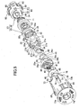
FIG. 5 is an exploded perspective view of a cylinder lock device. -
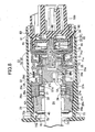
FIG. 6 is an enlarged sectional view taken along a line 6-6 inFIG. 3 . -
FIG. 7 is an enlarged sectional view taken along a line 7-7 inFIG. 4 . -
FIG. 8 is an enlarged sectional view taken along a line 8-8 inFIG. 2 with the inner cylinder being pushed in the OFF position. -
FIG. 9 is a perspective view of a cylinder body. -
FIG. 10 is a sectional view taken along a line 10-10 inFIG. 6 . -
FIG. 11 is a sectional view taken along a line 11-11 inFIG. 6 . -
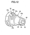
FIG. 12 is a perspective view of the inner cylinder. -
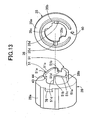
FIG. 13 is an exploded perspective view of the inner cylinder and an engaging member. -
FIG. 14 is a sectional view taken along a line 14-14 inFIG. 6 . -
FIG. 15 illustrates functions of guide and control means and guide means. - First in
FIGS. 1 and2 , to aside lid 22 mounted to aright end wall 21 a of aninstrument panel 21 of a left-hand drive vehicle, acylinder lock device 23 according to a preferred embodiment of the present invention is mounted with a front end thereof facing a surface of theside lid 22. The front end of thecylinder lock device 23 is covered with a side door (not shown) on a passenger side of the vehicle by closing the side door. - Also with reference to
FIGS. 3 and 4 , thecylinder lock device 23 includes acylinder lock 25 that is rotatable between an ON position and an OFF position by akey 24 inserted therein, and aswitch 26 for switching a switching mode according to a rotation operation of thecylinder lock 25. Theswitch 26 permits activation of a passenger side airbag (not shown) stored in a position corresponding to the passenger side of theinstrument panel 21 with thecylinder lock 25 being in the ON position, and inhibits the activation of the passenger side airbag with thecylinder lock 25 being in the OFF position. - In
FIGS. 5 to 8 , thecylinder lock 25 includes: acylinder body 28 having acylinder hole 27; aninner cylinder 29 inserted into thecylinder hole 27 rotatably between the ON position and the OFF position and axially movably between an advance position and a retracted position spaced apart from each other axially of thecylinder hole 27, and having akey insertion hole 30; first andsecond tumblers inner cylinder 29 so as to slide along a plane perpendicular to an axis of thekey insertion hole 30; areturn spring 33 that biases theinner cylinder 29 to be rotated from the OFF position to the ON position; apush spring 34 that biases theinner cylinder 29 toward the advance position; anengaging member 35 secured to theinner cylinder 29; and guide and control means 36 provided between theengaging member 35 and thecylinder body 28. - Also with reference to
FIGS. 9 to 11 , thecylinder body 28 integrally includes a largediameter cylinder portion 28a and a smalldiameter cylinder portion 28b connected to a rear end of the largediameter cylinder portion 28a, and is made of a light alloy such as a zinc alloy. Thecylinder hole 27 in thecylinder body 28 includes alarge diameter hole 27a with an opened front end, amiddle diameter hole 27b having a smaller diameter than thelarge diameter hole 27a and having a front end coaxially connected to a rear end of thelarge diameter hole 27a, and asmall diameter hole 27c having a smaller diameter than themiddle diameter hole 27b and coaxially connected to a rear end of themiddle diameter hole 27b. Thelarge diameter hole 27a and themiddle diameter hole 27b are provided on the side of the largediameter cylinder portion 28a, thesmall diameter hole 27c is provided on the side of the smalldiameter cylinder portion 28b, and anannular step 27d facing forward is formed between themiddle diameter hole 27b and thesmall diameter hole 27c. - In the large
diameter cylinder portion 28a of thecylinder body 28,first guide protrusions 38 protruding radially inwardly from four points circumferentially regularly spaced apart from each other on an inner periphery of thelarge diameter hole 27a, connected flush with an inner periphery of themiddle diameter hole 27b and axially extending, and foursecond guide protrusions 39 protruding radially inwardly from the inner periphery of thelarge diameter hole 27a in the middles of thefirst guide protrusions 38, connected flush with the inner periphery of themiddle diameter hole 27b and axially extending are integrally provided in a protruding manner. Between thelarge diameter hole 27a and themiddle diameter hole 27b,steps 27e placed respectively between the first andsecond guide protrusions first guide protrusions 38 are positioned to be retracted from the position of the front end of thelarge diameter hole 27a, front ends of thesecond guide protrusions 39 are positioned to be retracted from the position of the front ends of thefirst guide protrusions 38, and a width of eachfirst guide protrusion 38 circumferentially of thelarge diameter hole 27a is larger than a width of eachsecond guide protrusion 39. - Also with reference to
FIG. 12 , theinner cylinder 29 integrally includes: alarge diameter portion 29a having a larger diameter than thelarge diameter hole 27a of thecylinder hole 27 in thecylinder body 28 and placed forward of thecylinder body 28; a firstmiddle diameter portion 29b that can fit in thelarge diameter hole 27a; a secondmiddle diameter portion 29c that is slidably supported by inner peripheral surfaces of the first andsecond guide protrusions cylinder body 28 and can fit in themiddle diameter hole 27b of thecylinder hole 27; and asmall diameter portion 29d that slidably fits in thesmall diameter hole 27c of thecylinder hole 27, and is made of a light alloy such as a zinc alloy. In theinner cylinder 29, thekey insertion hole 30 having a rectangular section extending along a diameter line of thecylinder hole 27 is provided so as to open in a front end of theinner cylinder 29, and thekey 24 can be inserted into thekey insertion hole 30 from the front end of theinner cylinder 29. - The
inner cylinder 29 is inserted into thecylinder hole 27 rotatably between the ON position and the OFF position, and axially movably between the advance position (the position inFIGS. 6 and7 ) and the retracted position (the position inFIG. 8 ) spaced apart from each other axially of thecylinder hole 27. Thus, in the advance position of theinner cylinder 29, as shown inFIGS. 6 and7 , the firstmiddle diameter portion 29b of theinner cylinder 29 is placed to be separated forward from thelarge diameter hole 27a of thecylinder hole 27, the secondmiddle diameter portion 29c is placed to be supported by the inner peripheral surfaces of the first andsecond guide protrusions middle diameter hole 27b of thecylinder hole 27. In the retracted position of theinner cylinder 29, as shown inFIG. 8 , the firstmiddle diameter portion 29b is placed to fit in thelarge diameter hole 27a of thecylinder hole 27, and the secondmiddle diameter portion 29c is placed to partly fit in themiddle diameter hole 27b of thecylinder hole 27. - To the front end of the
inner cylinder 29, acover 46 having arectangular opening 45 corresponding to thekey insertion hole 30 is mounted so as to cover the front end of theinner cylinder 29. In a front end of thekey insertion hole 30, ashutter plate 47 that can cover theopening 45 from inside, aspindle 48 that rotatably supports theshutter plate 47, and aspring 49 that biases theshutter plate 47 so as to cover theopening 45 are housed, and thekey 24 is inserted into thekey insertion hole 30 so as to push open theshutter plate 47 with a tip thereof. - Also with reference to
FIGS. 13 and14 , thesmall diameter portion 29d of theinner cylinder 29 protrudes rearwardly from thecylinder body 28, and theengaging member 35 is secured to a protruding portion of thesmall diameter portion 29d from thecylinder body 28. Theengaging member 35 integrally includes: aring plate portion 35a coaxially surrounding thesmall diameter portion 29d; afitting cylinder portion 35b coaxially connected to a radially intermediate portion of thering plate portion 35a so as to fit the smalldiameter cylinder portion 28b of thecylinder body 28; engagingprotrusions ring plate portion 35a; andprotrusions ring plate portion 35a inwardly of thefitting cylinder portion 35b, and integrally connected to portions on an inner periphery of thefitting cylinder portion 35b closer to thering plate portion 35a. - On the other hand, in an outer periphery of the
small diameter portion 29d of theinner cylinder 29, a pair ofengaging recesses annular recess 41 formed into an annular shape so as to cross theengaging recesses 40 are provided. Thus, thesmall diameter portion 29d of theinner cylinder 29 is fitted into theengaging member 35 so that theengaging protrusions 35c are engaged with theengaging recesses 40 until theprotrusions 35d abut against the rear end of the smalldiameter cylinder portion 28b of thecylinder body 28, and an Etype retaining ring 42 that engages thering plate portion 35a of theengaging member 35 from the side opposite from the smalldiameter cylinder portion 28b of thecylinder body 28 is fitted to theannular recess 41. Specifically, theengaging member 35 is mounted to thesmall diameter portion 29d of theinner cylinder 29 relatively nonrotatably and axially immovably, and secured to thesmall diameter portion 29d. - The
return spring 33 is of a coil shape surrounding the smalldiameter cylinder portion 28b of thecylinder body 28 and thefitting cylinder portion 35b of the engagingmember 35, and one end of thereturn spring 33 is engaged with the smalldiameter cylinder portion 28b of thecylinder body 28. Specifically, the smalldiameter cylinder portion 28b partly has anotch 43, and one end of thereturn spring 33 is engaged with one circumferential end of thenotch 43. Also, alock protrusion 44 for preventing thereturn spring 33 from being easily removed from thenotch 43 integrally protrudes on thecylinder body 28 so as to protrude from a rear portion of one circumferential end toward the other circumferential end of thenotch 43. In thering plate portion 35a of the engagingmember 35, an engaginghole 50 with which the other end of thereturn spring 33 is engaged is provided. Thus, theinner cylinder 29 is biased to return from the OFF position toward the ON position by the spring force exerted by thereturn spring 33. - The guide and control means 36 is provided between the engaging
member 35 secured to theinner cylinder 29 and the rear end of thecylinder body 28, and includes theprotrusions member 35, andcams diameter cylinder portion 28b of thecylinder body 28 and against which theprotrusions - The
inner cylinder 29 is biased toward the advance position by thepush spring 34, and theprotrusions 35d of the engagingmember 35 secured to theinner cylinder 29 are biased to abut against thecams 51 formed on thecylinder body 28 placed forward of the engagingmember 35. - In
FIG. 15 , the cam 51 includes: an advance position side abutting surface 51a extending circumferentially of the cylinder body 28 and against which the protrusion 35d of the engaging member 35 it abutted with the inner cylinder 29 being in the advance position in the ON position; a retracted position side abutting surface 51b extending circumferentially of the cylinder body 28 and against which the protrusion 35d of the engaging member 35 is abutted immediately before the inner cylinder 29 reaches the OFF position in rotation of the inner cylinder 29 from the ON position to the OFF position; an inclined surface 51 c connecting between the advance position side abutting surface 51 a and the retracted position side abutting surface 51b so that the protrusion 35d is moved from the advance position side abutting surface 51a to the retracted position side abutting surface 51b against the biasing force of the push spring 34 with the rotation of the inner cylinder 29 from the ON position to the OFF position; and a control surface 51d connected perpendicularly to the retracted position side abutting surface 51b and axially extending so as to guide the movement of the inner cylinder 29 from the retracted position to the advance position by the biasing force of the push spring 34 when the inner cylinder 29 is rotated to the OFF position and control the rotation toward the OFF position when the inner cylinder 29 is moved to the advance position. - Specifically, the guide and control means 36 retracts the
inner cylinder 29 from the advance position to the retracted position against the biasing force of thepush spring 34 when theinner cylinder 29 is rotated from the ON position to the OFF position, advances theinner cylinder 29 from the retracted position to the advance position by the biasing force of thepush spring 34 in the OFF position, and prevents theinner cylinder 29 advanced to the advance position in the OFF position from being rotated from the OFF position to the ON position. - On the other hand, between the front end portion of the
cylinder body 28 and the front portion of theinner cylinder 29, guide means 52 is provided for guiding the movement of theinner cylinder 29 from the advance position to the retracted position by the guide and control means 36 when theinner cylinder 29 is rotated from the ON position to the OFF position. - The guide means 52 includes an
arcuate guide surface 53 formed on the front end of thecylinder body 28 to face forward, and anabutting protrusion 29e provided in the front portion of theinner cylinder 29 so as to abut against theguide surface 53 from forward. The abuttingprotrusion 29e is integrally provided on theinner cylinder 29 so as to protrude radially outwardly from the firstmiddle diameter portion 29b of theinner cylinder 29 to connect flush with an outer surface of thelarge diameter portion 29a of theinner cylinder 29. - The
guide surface 53 includes: an advance positionside abutting surface 53a extending circumferentially of thecylinder body 28 and against which the abuttingprotrusion 29e is abutted with theinner cylinder 29 being in the advance position in the ON position; a retracted positionside abutting surface 53b extending circumferentially of thecylinder body 28 and against which the abuttingprotrusion 29e is abutted with theinner cylinder 29 being rotated to the OFF position and in the retracted position; and aninclined surface 53c connecting between the advance positionside abutting surface 53 a and the retracted positionside abutting surface 53b and against which the abuttingprotrusion 29e is abutted when theinner cylinder 29 is moved from the advance position to the retracted position in the rotation from the ON position to the OFF position. - With reference to
FIG. 10 , thefirst tumbler 31 is provided in the secondmiddle diameter portion 29c of theinner cylinder 29 slidably along the plane perpendicular to the axis of thekey insertion hole 30, and between theinner cylinder 29 and thefirst tumbler 31, aspring 54 is provided that biases thefirst tumbler 31 so as to partly protrude from the outer surface of the secondmiddle diameter portion 29c of theinner cylinder 29. Thus, when thenormal key 24 is inserted into thekey insertion hole 30, thefirst tumbler 31 is housed in the secondmiddle diameter portion 29c of theinner cylinder 29 against a spring force of thespring 54. - The
inner cylinder 29 is rotated 900 between the ON position and the OFF position, and in the ON position and the OFF position of theinner cylinder 29, thefirst tumbler 31 is in a circumferential position corresponding to twosecond guide protrusions second guide protrusions 39 provided on the inner periphery of thecylinder body 28. Further, thefirst tumbler 31 is placed forward of thesecond guide protrusions 39 with theinner cylinder 29 being in the advance position, and a protruding portion of thefirst tumbler 31 from theinner cylinder 29 faces one of thesecond guide protrusions 39 from forward with theinner cylinder 29 being in the advance position in the ON position and the OFF position and thefirst tumbler 31 partly protruding from the secondmiddle diameter portion 29c of theinner cylinder 29 without thenormal key 24 being inserted into thekey insertion hole 30. Thus, even if theinner cylinder 29 is pressed from the advance position to the retracted position without thenormal key 24 being inserted into thekey insertion hole 30, thefirst tumbler 31 abuts against thesecond guide protrusions 39 to prevent retraction of theinner cylinder 29, and two of the foursecond guide protrusions 39 function as movement preventing portions that abut against thefirst tumbler 31 to prevent the retraction of theinner cylinder 29. - With reference to
FIG. 11 , thesecond tumbler 32 is provided in the secondmiddle diameter portion 29c of theinner cylinder 29 behind thefirst tumbler 31 slidably along the plane perpendicular to the axis of thekey insertion hole 30, and between theinner cylinder 29 and thesecond tumbler 32, aspring 55 is provided that biases thesecond tumbler 32 so as to partly protrude from the outer surface of the secondmiddle diameter portion 29c of theinner cylinder 29. Thus, when thenormal key 24 is inserted into thekey insertion hole 30, thesecond tumbler 32 is housed in the secondmiddle diameter portion 29c of theinner cylinder 29 against a spring force of thespring 55. - In the ON position and the OFF position of the
inner cylinder 29, thesecond tumbler 32 is in a circumferential position corresponding to twosecond guide protrusions first tumbler 31. Further, in a protruding portion of thesecond tumbler 32 from theinner cylinder 29, an engagingrecess 56 with which thesecond guide protrusion 39 is engaged is provided, and the engagingrecess 56 in the protruding portion of thesecond tumbler 32 from theinner cylinder 29 is placed to partly house thesecond guide protrusion 39 with theinner cylinder 29 being in the advance position in the ON position and the OFF position and thesecond tumbler 32 partly protruding from the secondmiddle diameter portion 29c of theinner cylinder 29 without thenormal key 24 being inserted into thekey insertion hole 30. - With the
inner cylinder 29 being in the advance position in the OFF position, the rotation of theinner cylinder 29 toward the ON position by thereturn spring 33 is controlled by theprotrusions 35d of the guide and control means 36 abutting against thecontrol surfaces 51d. In this case, the first andsecond tumblers inner cylinder 29 without thenormal key 24 being inserted into thekey insertion hole 30 do not abut against and engage with thesecond guide protrusion 39, thereby preventing the biasing force by thereturn spring 33 from being applied between the first andsecond tumblers cylinder body 28. On the other hand, with theinner cylinder 29 being in the advance position in the ON position, when a rotating force toward the OFF position is applied to theinner cylinder 29 without thenormal key 24 being inserted into thekey insertion hole 30, thesecond guide protrusion 39 placed in the engagingrecess 56 of thesecond tumbler 32 is abutted against and engaged with thesecond tumbler 32, thereby preventing theinner cylinder 29 from being rotated toward the OFF position. - In
FIGS. 6 to 8 , theswitch 26 comprises aswitch case 60 made of synthetic resin and fixedly placed behind thecylinder body 28, and aswitch mechanism 61 housed in theswitch case 60. Theswitch case 60 includes afirst case member 62 made of synthetic resin and formed into a bowl shape opening rearwardly, and asecond case member 63 having acylinder portion 63a with a tip portion fitting in a rear opening end of thefirst case member 62, connected to each other, and acoupler 63b is formed integrally with thesecond case member 63. - The
switch mechanism 61 includes: a ring plate shapedcontact support portion 64 formed integrally with thesecond case member 63; a disk shapedrotation member 65 made of synthetic resin and facing thecontact support portion 64 from forward; a connectingshaft 66 made of synthetic resin and which rotatably passes through a throughhole 67 provided in the middle portion of thefirst case member 62 and has a rear portion rotatably supported by thesecond case member 63; a plurality of fixed contacts (not shown) provided on thecontact support portion 64; and a plurality ofmovable contacts 69 provided on therotation member 65 so as to switch conduction and interruption of the fixed contacts according to rotation of therotation member 65. - The connecting
shaft 66 is relatively nonrotatably connected to therotation member 65, and in this embodiment, the connectingshaft 66 and therotation member 65 are integrally formed. - A front end of the connecting
shaft 66 is relatively nonrotatably fitted in a connectingrecess 70 provided in the rear end of theinner cylinder 29 and thus connected to theinner cylinder 29, and the connectingshaft 66 and therotation member 65 rotate with rotation of theinner cylinder 29. - The
push spring 34 is made of conductive metal and formed into a coil shape. Thepush spring 34 is provided in a compressed manner between aspring receiving member 71 secured to the rear end of theinner cylinder 29, and thefirst case member 62 of theswitch case 60 connected to thecylinder body 28 and thus fixedly placed behind thecylinder body 28. - The
spring receiving member 71 is made of nonconductive material and integrally includes: aninner cylinder portion 71a in which thesmall diameter portion 29d that is the rear end of theinner cylinder 29 is fitted; anannular abutting portion 71b overhanging radially inwardly from theinner cylinder portion 71a so as to abut against the rear end surface of theinner cylinder 29; aflange 71 c overhanging radially outwardly from the inner cylinder portion 7 1 a; and anouter cylinder portion 71d connected to an outer periphery of theflange 71 c and extending toward theswitch case 60. Between thefirst case member 62 of theswitch case 60 and theflange 71 c, thepush spring 34 is provided so as to surround theinner cylinder portion 71 a. - Thus, the
spring receiving member 71 is biased by thepush spring 34 so that the abuttingportion 71b abuts against the rear end surface of theinner cylinder 29. Thepush spring 34 is provided between thespring receiving member 71 in which the rear end of theinner cylinder 29 is fitted, and thefirst case member 62 of theswitch case 60 fixedly placed behind thecylinder body 28, and thus thespring receiving member 71 is substantially secured to the rear end of theinner cylinder 29. - The
cylinder lock 25 and theswitch 26 are connected via ahousing 73 made of synthetic resin. Thehousing 73 is made of synthetic resin and formed into a closed-end cylindrical shape so that one end of acylinder portion 73b is integrally connected to anend wall 73a having anopening 74 communicating with the front end of thekey insertion hole 30, and theend wall 73a is formed into a ring shape so that an outer periphery thereof overhangs radially outwardly more than the outer periphery of thecylinder portion 73b. In one end of thehousing 73, thecylinder body 28 of thecylinder lock 25 is fitted. To a front surface of thecover 46 having anopening 45 communicating with the front end of thekey insertion hole 30 and mounted to the front end of theinner cylinder 29, aseal member 76 having anopening 75 that provides communication between theopening 45 and theopening 74 in theend wall 73a is bonded, and theseal member 76 is brought into contact with an inner surface of theend wall 73a when theinner cylinder 29 is in the advance position. - On a front surface of the
end wall 73a, the ON position (ON) and the OFF position (OFF) for indicating rotation positions of theinner cylinder 29, that is, the positions of thekey insertion hole 30 and theopenings - In the
cylinder portion 73b of thehousing 73, slits 77 and 77 axially extending in a plurality of, for example, two circumferential points on thehousing 73 so as to be closed at one ends and opened at the other ends in the other end of thehousing 73, that is, the other end of thecylinder portion 73b, a plurality of, for example, two first engagingholes slits 77 and theend wall 73a and with which first engagingprotrusions cylinder body 28 fitted in one end of thehousing 73 are resiliently engaged respectively, and a plurality of, for example, four second engagingholes 81 placed in the other end of thecylinder portion 73b between theslits 77 and with which a plurality of, for example, four second engagingprotrusions 80 integrally protruding on the outer periphery of thesecond case member 63 of theswitch case 60 at least partly fitted in the other end of thecylinder portion 73b of thehousing 73 are resiliently engaged respectively. - On the other hand, in the
second case member 63 that constitutes part of theswitch case 60, a plurality of, for example, twoopening preventing portions housing 73, that is, the other end side of thecylinder portion 73b between theslits 77 according to theswitch case 60 at least partly (in this embodiment, partly) fitting in the other end of thehousing 73. - Thus, the
cylinder body 28 is fitted in one end of thehousing 73 from the other end of thehousing 73, and secured to thehousing 73 by the first engagingprotrusions 78 on thecylinder body 28 being resiliently engaged with the first engagingholes 79 in thehousing 73. Theswitch case 60 partly fitted in the other end of thehousing 73 is secured to thehousing 73 by the secondengaging protrusions 80 being resiliently engaged with the second engagingholes 81 on the other end side of thehousing 73. - For mounting the
cylinder lock device 23 including thecylinder lock 25 and theswitch 26 connected via thehousing 73, a mountingcylinder portion 83 passing through anopening 84 provided in theright end wall 21a of theinstrument panel 21 and extending inwardly of theinstrument panel 21 is provided integrally with theside lid 22. Thus, as clearly shown inFIG. 6 , thecylinder lock device 23 is inserted into the mountingcylinder portion 83 so that an outer peripheral portion of theend wall 73a at the front end of thecylinder lock device 23 engages a peripheral edge at an outer end of the mountingcylinder portion 83. Further, base ends of engagingarm portions cylinder portion 73b in the middle of theslits housing 73, and tips of thearm portions 85 that are brought into slide contact with an inner surface of the mountingcylinder portion 83 and bent radially inwardly in insertion of thecylinder lock device 23 into the mountingcylinder portion 83 resiliently engage an inner end of the mountingcylinder portion 83 according to the insertion of thecylinder lock device 23 until the outer peripheral portion of theend wall 73a engages the peripheral edge at the outer end of the mountingcylinder portion 83, and thus thecylinder lock device 23 is mounted to theside lid 22. - Next, operations of the embodiment will be described. In the
cylinder lock 25, theinner cylinder 29 having thekey insertion hole 30 is inserted into thecylinder hole 27 rotatably between the ON position and the OFF position and axially movably between the advance position and the retracted position spaced apart from each other axially of thecylinder hole 27 in thecylinder body 28, and rotationally biased toward the ON position by the spring force of thereturn spring 33 and biased toward the advance position by thepush spring 34. The guide and control means 36 provided between the engagingmember 35 secured to theinner cylinder 29 and thecylinder body 28 retracts theinner cylinder 29 from the advance position to the retracted position against the biasing force of thepush spring 34 when theinner cylinder 29 is rotated from the ON position to the OFF position by thenormal key 24 inserted into thekey insertion hole 30, advances theinner cylinder 29 from the retracted position to the advance position by the biasing force of thepush spring 34 in the OFF position, and prevents theinner cylinder 29 in the advance position in the OFF position from being rotated from the OFF position to the ON position. - Specifically, the
normal key 24 is inserted into thekey insertion hole 30 to rotate theinner cylinder 29 from the ON position to the OFF position, and then the guide and control means 36 causes theinner cylinder 29 to be held in the OFF position against the spring force of thereturn spring 36 without being rotated toward the ON position, in the advance position in the OFF position. Thus, there is no need that the first andsecond tumblers inner cylinder 29 so as to protrude from the outer periphery of theinner cylinder 29 when thenormal key 24 is not inserted into thekey insertion hole 30 for determining whether the key 24 inserted into thekey insertion hole 30 is thenormal key 24 are abutted against and engaged with thecylinder body 28 in the protruding position to hold the OFF position of theinner cylinder 29, and the guide and control means 36 provided between the engagingmember 35 secured to theinner cylinder 29 and thecylinder body 28 receives the spring force of thereturn spring 33. Thus, the spring force of thereturn spring 33 is not applied between the first andsecond tumblers cylinder body 28. This prevents bad (heavy) feeling of insertion of the key 24 into thekey insertion hole 30. - Further, the
inner cylinder 29 is held in the OFF position without the first andsecond tumblers inner cylinder 29, thus theinner cylinder 29 can be held in the OFF position whether the key 24 is removed or not in the OFF position, which increases convenience. - The
first tumbler 31 protruding from the outer periphery of theinner cylinder 29 in the OFF position is engaged with and abutted against one of the foursecond guide protrusions 39 provided on the inner periphery of thecylinder hole 27 in thecylinder body 28 to prevent retraction of theinner cylinder 29 from the advance position to the retracted position. Thus, even if theinner cylinder 29 is pushed toward the retracted position without thenormal key 24 being inserted into thekey insertion hole 30 in the OFF position, theinner cylinder 29 cannot be retracted from the advance position to the retracted position, and thus theinner cylinder 29 is not returned toward the ON position. Also, thefirst tumbler 31 for determining whether the key 24 inserted into thekey insertion hole 30 is thenormal key 24 is used as part of a configuration for preventing retraction of theinner cylinder 29, which prevents an increase in the number of components. - In the
cylinder lock device 23, thecylinder lock 25 including thecylinder body 28 and theinner cylinder 29 inserted into thecylinder hole 27 in thecylinder body 28, and theswitch 26 comprising theswitch case 60 placed behind thecylinder body 28 and theswitch mechanism 61 housed in theswitch case 60 and interlocked with and connected to theinner cylinder 29 are connected via thehousing 63. In thehousing 73 made of synthetic resin, formed into a closed-end cylindrical shape and having theend wall 73a at one end, there are provided the plurality of first engagingholes 79 with which the first engagingprotrusions 78 integrally protruding on the plurality of points on the outer periphery of thecylinder body 28 fitted in one end of thehousing 73 are resiliently engaged respectively, and the plurality of second engagingholes 81 with which the plurality of secondengaging protrusions 80 integrally protruding on the outer periphery of thesecond case member 63 that constitutes part of theswitch case 60 at least partly fitted in the other end of thehousing 73 are resiliently engaged respectively. Thus, thecylinder body 28 fitted in one end of thehousing 73 is secured to thehousing 73, and theswitch case 60 at least partly fitted in the other end of thehousing 73 is secured to the other end of thehousing 73, thereby increasing connection rigidity between theswitch case 60 and thecylinder body 28. - Further, in the
housing 73, theslits 77 axially extending in the plurality of circumferential points on thehousing 73 so as to be closed at one ends and opened at the other ends into the other end of thehousing 73 are provided, and the first engagingholes 79 are placed between one ends of theslits 77 and theend wall 73a, and thus the first engagingprotrusions 78 are brought into contact with the inner surface of thehousing 73 only in a short range, at the one ends of theslits 77 and the first engagingholes 79, when thecylinder body 28 is fitted in thehousing 73 from the other end side. The plurality of second engagingholes 81 with which the secondengaging protrusions 80 on the outer periphery of theswitch case 60 are resiliently engaged respectively are placed in the other end of thehousing 73 between theslits 77, and thus the secondengaging protrusions 80 are also brought into contact with the inner surface of thehousing 73 only in a short range when theswitch case 60 is at least partly fitted in the other end of thehousing 73. Specifically, when thecylinder lock 25 and theswitch 26 are connected via thehousing 73, the first engagingprotrusions 78 and the secondengaging protrusions 80 are brought into contact with the inner surface of thehousing 73 in a short distance to improve an assemblability. - The plurality of
slits 77 are provided, thus the other end of thehousing 73 is easily opened radially outward on opposite sides of theslits 77, and the other end of thehousing 73 may be warped radially outwardly on the opposite sides of theslits 77 in forming thehousing 73. However, in theswitch case 60, the plurality ofopening preventing portions 82 are provided that abut from outside against the outer surface on the other end side of thehousing 73 between theslits 77 according to theswitch case 60 at least partly fitting in the other end of thehousing 73. Thus, even if an external force is applied to theswitch case 60, the engagement and securing of theswitch case 60 with and to thehousing 73 is not easily released. Further, theopening preventing portions 82 are integrally provided in thesecond case member 63 that constitutes part of theswitch case 60, thereby eliminating the need for components intended for preventing opening and preventing an increase in the number of components. - To the rear end of the
inner cylinder 29, thespring receiving member 71 made of nonconductive material is secured, and thespring receiving member 71 integrally includes theinner cylinder portion 71a in which the rear end of theinner cylinder 29 is fitted, theannular abutting portion 71b overhanging radially inwardly from theinner cylinder portion 71a so as to abut against the rear end surface of theinner cylinder 29, theflange 71c overhanging radially outwardly from theinner cylinder portion 71 a, and theouter cylinder portion 71 d connected to the outer periphery of theflange 71c and extending toward theswitch case 60, and thepush spring 34 is provided in a compressed manner between theflange 71c and theswitch case 60. Thus, a long creepage distance of thespring receiving member 71 can be obtained between theinner cylinder 29 made of metal and thepush spring 34 made of metal, thereby preventing static electricity from passing from theinner cylinder 29 to thepush spring 34, and thus preventing a high voltage from being applied to theswitch mechanism 61 and a control unit that receives signals from theswitch mechanism 61. Further, the rear end of theinner cylinder 29 is covered with the abuttingportion 71b of thespring receiving member 71, thereby preventing electrical discharge from the rear end of theinner cylinder 29 through a space toward theswitch case 60. - A preferred embodiment of the present invention has been described, but the present invention is not limited to this embodiment, and various design choices may be made without departing from the present invention described in claims.
- For example, in the embodiment, the engaging
member 35 separate from theinner cylinder 29 is secured to theinner cylinder 29, but theinner cylinder 29 and the engagingmember 35 may be integrally formed. - In the embodiment, the
cylinder lock device 23 includes thecylinder lock 25 that is rotatable between the ON position and the OFF position, and theswitch 26 for switching the switching mode according to the rotation operation of thecylinder lock 25. However, an activation mechanism in place of the switch mechanism may be applied to be activated according to the rotation operation of thecylinder lock 25.
Claims (2)
- A cylinder lock device comprising:a cylinder body (28) having a cylinder hole (27);an inner cylinder (29) inserted into the cylinder hole (27) rotatably between first and second rotation positions and axially movably between an advance position and a retracted position spaced apart from each other axially of the cylinder hole (27), and having a key insertion hole (30);a tumbler (31, 32) provided in the inner cylinder (29) so as to slide along a plane perpendicular to an axis of the key insertion hole (30) between a protruding position where the tumbler protrudes from an outer periphery of the inner cylinder (29) when a normal key (24) is not inserted into the key insertion hole (30) and a housed position where the tumbler is housed in the inner cylinder (29) when the normal key (24) is inserted;a return spring (33) that biases the inner cylinder (29) to be rotated from the second rotation position to the first rotation position;biasing means (34) for biasing the inner cylinder (29) toward the advance position;an engaging member (35) secured to or integrally formed with the inner cylinder (29); andguide and control means (36) provided between the engaging member (35) and the cylinder body (28),wherein the guide and control means (36) retracts the inner cylinder (29) from the advance position to the retracted position against a biasing force of the biasing means (34) when the inner cylinder (29) is rotated from the first rotation position to the second rotation position by the normal key (24) inserted into the key insertion hole (30), advances the inner cylinder (29) from the retracted position to the advance position by the biasing force of the biasing means (34) in the second rotation position, and prevents the inner cylinder (29) in the advance position in the second rotation position from being rotated from the second rotation position to the first rotation position.
- The cylinder lock device according to claim 1, wherein a movement preventing portion (39) that is engaged with and abutted against the tumbler (31) protruding from the outer periphery of the inner cylinder (29) in the advance position in the second rotation position to prevent retraction of the inner cylinder (29) from the advance position toward the retracted position is provided on an inner periphery of the cylinder hole (27).
Applications Claiming Priority (1)
| Application Number | Priority Date | Filing Date | Title |
|---|---|---|---|
| JP2007231070A JP4398998B2 (en) | 2007-09-06 | 2007-09-06 | Cylinder lock device |
Publications (3)
| Publication Number | Publication Date |
|---|---|
| EP2034111A2 true EP2034111A2 (en) | 2009-03-11 |
| EP2034111A3 EP2034111A3 (en) | 2010-01-20 |
| EP2034111B1 EP2034111B1 (en) | 2011-10-19 |
Family
ID=40261969
Family Applications (1)
| Application Number | Title | Priority Date | Filing Date |
|---|---|---|---|
| EP20080252708 Not-in-force EP2034111B1 (en) | 2007-09-06 | 2008-08-15 | Cylinder lock device |
Country Status (2)
| Country | Link |
|---|---|
| EP (1) | EP2034111B1 (en) |
| JP (1) | JP4398998B2 (en) |
Citations (1)
| Publication number | Priority date | Publication date | Assignee | Title |
|---|---|---|---|---|
| JP2002106225A (en) | 2000-09-29 | 2002-04-10 | Honda Lock Mfg Co Ltd | Glove box locking device |
Family Cites Families (8)
| Publication number | Priority date | Publication date | Assignee | Title |
|---|---|---|---|---|
| US2046831A (en) * | 1931-07-06 | 1936-07-07 | Yale & Towne Mfg Co | Lock |
| US1951418A (en) * | 1931-09-16 | 1934-03-20 | Briggs & Stratton Corp | Lock |
| US2440690A (en) * | 1946-07-11 | 1948-05-04 | Briggs & Stratton Corp | Switch |
| US2679557A (en) * | 1951-07-16 | 1954-05-25 | United Specialties Co | Starter ignition switch |
| US3522394A (en) * | 1969-01-24 | 1970-07-28 | Donald W Bellrose | Combined automobile ignition and light switch |
| DE7218524U (en) * | 1972-05-17 | 1972-08-17 | Rau G Gmbh | Light and starter switches for motor vehicles |
| US4956983A (en) * | 1988-09-22 | 1990-09-18 | Kabushiki Kaisha Tokai Rika Denki Seisakusho | Locking apparatus with a key |
| US6122944A (en) * | 1998-03-24 | 2000-09-26 | Methode Electronics, Inc. | Key operated rotary switch for disabling an automobile air bag supplemental restraint system |
-
2007
- 2007-09-06 JP JP2007231070A patent/JP4398998B2/en active Active
-
2008
- 2008-08-15 EP EP20080252708 patent/EP2034111B1/en not_active Not-in-force
Patent Citations (1)
| Publication number | Priority date | Publication date | Assignee | Title |
|---|---|---|---|---|
| JP2002106225A (en) | 2000-09-29 | 2002-04-10 | Honda Lock Mfg Co Ltd | Glove box locking device |
Also Published As
| Publication number | Publication date |
|---|---|
| EP2034111B1 (en) | 2011-10-19 |
| JP2009062721A (en) | 2009-03-26 |
| JP4398998B2 (en) | 2010-01-13 |
| EP2034111A3 (en) | 2010-01-20 |
Similar Documents
| Publication | Publication Date | Title |
|---|---|---|
| EP1845223B1 (en) | Key cylinder | |
| KR101157899B1 (en) | Lead switchgear | |
| US20090236863A1 (en) | Electric door latch apparatus | |
| EP2042672A1 (en) | Electrical lock device | |
| CN103703200A (en) | Lock device for opening/closing member | |
| GB2329927A (en) | Vehicle door latch of reduced thickness with self-cancelling lever on an exterior side of a ratchet pin | |
| KR100439486B1 (en) | Hinge device and portable electronic device | |
| EP2034111B1 (en) | Cylinder lock device | |
| JP7481227B2 (en) | Door handle device | |
| JP4792435B2 (en) | Cylinder lock device | |
| JP4792436B2 (en) | Cylinder lock device | |
| US20210238896A1 (en) | Vehicular door lock device | |
| JP2013053488A (en) | Lock device of vehicle door | |
| JP3819522B2 (en) | Steering lock device with unauthorized unlocking prevention function | |
| JP7804602B2 (en) | Cylinder lock protection device | |
| JP4214243B2 (en) | Glove box opening / closing structure | |
| JP3710894B2 (en) | Door lock | |
| JP3358980B2 (en) | Vehicle door lock device | |
| JP2573166B2 (en) | Lock handle device for drawer rotating door | |
| JP7112985B2 (en) | electric steering lock device | |
| JP3784489B2 (en) | Steering lock device | |
| JP3159302B2 (en) | Steering lock device | |
| JP2008031732A (en) | Cylinder lock | |
| JPH10266657A (en) | Steering lock device | |
| JP5215259B2 (en) | Sliding door finger clamp |
Legal Events
| Date | Code | Title | Description |
|---|---|---|---|
| PUAI | Public reference made under article 153(3) epc to a published international application that has entered the european phase |
Free format text: ORIGINAL CODE: 0009012 |
|
| AK | Designated contracting states |
Kind code of ref document: A2 Designated state(s): AT BE BG CH CY CZ DE DK EE ES FI FR GB GR HR HU IE IS IT LI LT LU LV MC MT NL NO PL PT RO SE SI SK TR |
|
| AX | Request for extension of the european patent |
Extension state: AL BA MK RS |
|
| PUAL | Search report despatched |
Free format text: ORIGINAL CODE: 0009013 |
|
| AK | Designated contracting states |
Kind code of ref document: A3 Designated state(s): AT BE BG CH CY CZ DE DK EE ES FI FR GB GR HR HU IE IS IT LI LT LU LV MC MT NL NO PL PT RO SE SI SK TR |
|
| AX | Request for extension of the european patent |
Extension state: AL BA MK RS |
|
| RIC1 | Information provided on ipc code assigned before grant |
Ipc: H01H 27/06 20060101ALI20091211BHEP Ipc: E05B 29/00 20060101AFI20090127BHEP Ipc: E05B 9/04 20060101ALI20091211BHEP |
|
| 17P | Request for examination filed |
Effective date: 20100323 |
|
| AKX | Designation fees paid |
Designated state(s): DE FR GB |
|
| GRAP | Despatch of communication of intention to grant a patent |
Free format text: ORIGINAL CODE: EPIDOSNIGR1 |
|
| RIC1 | Information provided on ipc code assigned before grant |
Ipc: E05B 29/00 20060101AFI20110304BHEP Ipc: E05B 9/04 20060101ALI20110304BHEP Ipc: H01H 27/06 20060101ALI20110304BHEP |
|
| GRAS | Grant fee paid |
Free format text: ORIGINAL CODE: EPIDOSNIGR3 |
|
| RIN1 | Information on inventor provided before grant (corrected) |
Inventor name: NEI, IKUHIRO Inventor name: MIYATA, KAZUHIRO |
|
| GRAA | (expected) grant |
Free format text: ORIGINAL CODE: 0009210 |
|
| AK | Designated contracting states |
Kind code of ref document: B1 Designated state(s): DE FR GB |
|
| REG | Reference to a national code |
Ref country code: GB Ref legal event code: FG4D |
|
| REG | Reference to a national code |
Ref country code: DE Ref legal event code: R096 Ref document number: 602008010577 Country of ref document: DE Effective date: 20111229 |
|
| PLBE | No opposition filed within time limit |
Free format text: ORIGINAL CODE: 0009261 |
|
| STAA | Information on the status of an ep patent application or granted ep patent |
Free format text: STATUS: NO OPPOSITION FILED WITHIN TIME LIMIT |
|
| 26N | No opposition filed |
Effective date: 20120720 |
|
| REG | Reference to a national code |
Ref country code: DE Ref legal event code: R097 Ref document number: 602008010577 Country of ref document: DE Effective date: 20120720 |
|
| REG | Reference to a national code |
Ref country code: FR Ref legal event code: PLFP Year of fee payment: 9 |
|
| PGFP | Annual fee paid to national office [announced via postgrant information from national office to epo] |
Ref country code: GB Payment date: 20160810 Year of fee payment: 9 |
|
| PGFP | Annual fee paid to national office [announced via postgrant information from national office to epo] |
Ref country code: FR Payment date: 20160712 Year of fee payment: 9 |
|
| GBPC | Gb: european patent ceased through non-payment of renewal fee |
Effective date: 20170815 |
|
| REG | Reference to a national code |
Ref country code: FR Ref legal event code: ST Effective date: 20180430 |
|
| PG25 | Lapsed in a contracting state [announced via postgrant information from national office to epo] |
Ref country code: GB Free format text: LAPSE BECAUSE OF NON-PAYMENT OF DUE FEES Effective date: 20170815 |
|
| PG25 | Lapsed in a contracting state [announced via postgrant information from national office to epo] |
Ref country code: FR Free format text: LAPSE BECAUSE OF NON-PAYMENT OF DUE FEES Effective date: 20170831 |
|
| REG | Reference to a national code |
Ref country code: DE Ref legal event code: R081 Ref document number: 602008010577 Country of ref document: DE Owner name: MINEBEA ACCESSSOLUTIONS INC., JP Free format text: FORMER OWNER: KABUSHIKI KAISHA HONDA LOCK, MIYAZAKI, JP |
|
| PGFP | Annual fee paid to national office [announced via postgrant information from national office to epo] |
Ref country code: DE Payment date: 20230821 Year of fee payment: 16 |
|
| REG | Reference to a national code |
Ref country code: DE Ref legal event code: R119 Ref document number: 602008010577 Country of ref document: DE |
|
| PG25 | Lapsed in a contracting state [announced via postgrant information from national office to epo] |
Ref country code: DE Free format text: LAPSE BECAUSE OF NON-PAYMENT OF DUE FEES Effective date: 20250301 |