EP2033854A1 - Retainer and inflator - Google Patents
Retainer and inflator Download PDFInfo
- Publication number
- EP2033854A1 EP2033854A1 EP07744872A EP07744872A EP2033854A1 EP 2033854 A1 EP2033854 A1 EP 2033854A1 EP 07744872 A EP07744872 A EP 07744872A EP 07744872 A EP07744872 A EP 07744872A EP 2033854 A1 EP2033854 A1 EP 2033854A1
- Authority
- EP
- European Patent Office
- Prior art keywords
- retainer
- inflator
- gas
- filter
- pressure
- Prior art date
- Legal status (The legal status is an assumption and is not a legal conclusion. Google has not performed a legal analysis and makes no representation as to the accuracy of the status listed.)
- Granted
Links
Images



Classifications
-
- B—PERFORMING OPERATIONS; TRANSPORTING
- B60—VEHICLES IN GENERAL
- B60R—VEHICLES, VEHICLE FITTINGS, OR VEHICLE PARTS, NOT OTHERWISE PROVIDED FOR
- B60R21/00—Arrangements or fittings on vehicles for protecting or preventing injuries to occupants or pedestrians in case of accidents or other traffic risks
- B60R21/02—Occupant safety arrangements or fittings, e.g. crash pads
- B60R21/16—Inflatable occupant restraints or confinements designed to inflate upon impact or impending impact, e.g. air bags
- B60R21/26—Inflatable occupant restraints or confinements designed to inflate upon impact or impending impact, e.g. air bags characterised by the inflation fluid source or means to control inflation fluid flow
- B60R21/264—Inflatable occupant restraints or confinements designed to inflate upon impact or impending impact, e.g. air bags characterised by the inflation fluid source or means to control inflation fluid flow using instantaneous generation of gas, e.g. pyrotechnic
- B60R21/2644—Inflatable occupant restraints or confinements designed to inflate upon impact or impending impact, e.g. air bags characterised by the inflation fluid source or means to control inflation fluid flow using instantaneous generation of gas, e.g. pyrotechnic using only solid reacting substances, e.g. pellets, powder
-
- F—MECHANICAL ENGINEERING; LIGHTING; HEATING; WEAPONS; BLASTING
- F42—AMMUNITION; BLASTING
- F42B—EXPLOSIVE CHARGES, e.g. FOR BLASTING, FIREWORKS, AMMUNITION
- F42B3/00—Blasting cartridges, i.e. case and explosive
- F42B3/04—Blasting cartridges, i.e. case and explosive for producing gas under pressure
-
- F—MECHANICAL ENGINEERING; LIGHTING; HEATING; WEAPONS; BLASTING
- F42—AMMUNITION; BLASTING
- F42B—EXPLOSIVE CHARGES, e.g. FOR BLASTING, FIREWORKS, AMMUNITION
- F42B3/00—Blasting cartridges, i.e. case and explosive
- F42B3/26—Arrangements for mounting initiators; Accessories therefor, e.g. tools
Definitions
- the present invention relates to a retainer which is one of the constituent parts of an inflator, and to the inflator equipped with this retainer.
- Inflator generates gas and the gas is supplied to the airbag which is installed in automobiles as a safety device.
- Airbag device comprises an inflator which is a gas-generating device, and an airbag.
- the airbag deploys due to the gas generated by the inflator, protecting passengers from impact during a collision.
- an inflator 1 typically includes a pressure container 2 having a diffuser 2a and a shallow dish base 2b, and an ignition means 3 operating due to an electrical signal generated after a collision is detected and gas generant 4 ignited by the ignition means 3 are housed in the pressure container 2.
- the ignition means 3 is composed of an initiator 3a and ignition enhancer 3b.
- the gas generant 4 bums, and instantaneously harmless gas is generated.
- the generated gas passes through a filter 5 and is finally discharged from gas exits 2aa.
- a diffuser 2a shown separately in FIG. 7 (a) in a state prior to welding, is welded to the base 2b, as shown in FIG. 7 (b) , so that the gas generant 4 is enclosed.
- Patent Reference 1 Japanese Laid-Open Patent Application No. H11-334517
- a disk-shaped retainer 7 as shown in FIG. 8 is fixed onto a tube 6 which separates the ignition means 3 from the gas generant 4, thereby retaining the filter 5 and the gas generant 4.
- This retainer 7 also serves the function of preventing gas leakage from between the inner surface of the diffuser 2a and the filter 5 when the inflator 1 operates.
- the pressure container of inflator expands greatly, as a result of the combustion pressure of the gas generant when the inflator operates. As this happens, the retainer also expands greatly in an outward direction shown in FIG. 10 , from the state prior to the inflator operation shown in FIG. 9 .
- the retainer 7 having a crimped edge 7a on the outer periphery is believed to be effective in sealing the large gaps formed between the filter and the retainer when the inflator operates.
- the retainer 7 with the crimped edge can maintain a sealed state of the gap between the retainer 7 and the filter 5, even if the pressure container 2 expands and changes its shape.
- the crimped edge must be fabricated in a shape so that the crimped edge will enter the filter in the state of its arrangement. Accordingly, the shape of the retainer becomes complicated. Furthermore, high accuracy of manufacturing is required for positioning an engaging member to engage with the tube, with the result that production is no longer easy, and the manufacturing costs greatly increase.
- the problem which the present invention aims to solve is that in the case of a conventional retainer, high accuracy of manufacturing is required, production is no longer easy, and it becomes extremely difficult to match the positions in order to seal the large gap between the filter and the retainer which are formed when the inflator operates.
- An object of the present invention is to provide a retainer which reliably prevents leakage of gas from between the retainer and a filter, and has a simple construction without negative effects on productivity.
- the retainer has a plate-shaped design and is inserted into the pressure container of inflator which generates gas being supplied to airbag.
- the retainer comprises an engaging section formed at the center which engages with a tube provided to separate an ignition means from a gas generant.
- the retainer also comprises at least one pressure release hole provided on the outer periphery side of the engaging section.
- the positions of the pressure release holes can be determined in any desired manner, but it is preferable when they are provided in a position according to point symmetry with respect to the center of the retainer or in a position according to line symmetry with respect to the center line of the retainer, so that the pressure between the retainer and the pressure container is distributed uniformly.
- the pressure release holes are provided on a plurality of circumferences, the pressure can be favorably distributed between the retainer and the pressure container.
- the pressure release holes are provided on a constant radius, it preferably reduces the excessive release of pressure from the retainer.
- the pressure balance on the front and back sides of the retainer is maintained during operation, and there is little deformation of the retainer caused by combustion pressure. Therefore, close contact is maintained between the step portion on the outer periphery side of the retainer and the inner side of the filter. Accordingly, it is possible to effectively prevent leakage of gas from the end of the filter, and there is little solid residue in the gas discharged from the gas discharge holes of the pressure container to outside of the inflator.
- an engaging section is formed to engage with the tube at the center, and at least one pressure release hole is provided on the outer periphery side from this engaging section.
- the present invention makes it possible to reduce deformation of the retainer due to combustion pressure, and makes it possible to maintain a state of close contact between the retainer and the filter, and makes it possible to reduce solid residue in gas discharged from the gas discharge holes of the pressure container to outside of the inflator.
- the present invention has a simple construction, and is easy to manufacture.
- the present invention also achieves the object of preventing gas from leaking between the retainer and the filter as much as possible, by providing at least one pressure release hole on the outer periphery side of the engaging section formed which engages with the tube formed in the center.
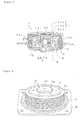
- FIG. 1 to FIG. 4 are used to describe the preferred embodiment of the present invention.
- FIG. 1 is an upper perspective view of a retainer of the present invention.
- FIG. 2 is an upper perspective view of the state in which the retainer is attached before welding.
- FIG. 3 is a drawing describing the mechanism whereby the amount of residue is reduced in a present invention inflator with the present invention retainer attached.
- FIG. 4 is an upper perspective view of the state when the diffuser is detached after operation of the present invention inflator.
- the present invention retainer 11 has an engaging section 11a formed centrally for the purpose of engaging with the front end of the tube 6 disposed within the pressure container 2.
- six (6) pressure release holes 11b are provided in a constant radius above the insertion position of the gas generant 4 on the outer periphery side of the engaging section 11a, for example.
- these pressure release holes 11b are provided at circumferentially equidistant positions, so that the gas pressure balance is suitably maintained on the front and back sides of the retainer.
- the radial position and the number thereof are determined for the purpose.
- step portion 11c formed at the area of contact with the filter 5 on the outer periphery side.
- This step portion 11c is formed so as to lengthen the gas passageway between the retainer 11 and the filter 5, making it difficult for the gas to pass through.
- the filter 5 there is no need to match with the filter 5 with high accuracy like a crimped edge 7a of the retainer 7 with the crimped edge shown in FIG. 10 .
- Such a present invention retainer 11 has a simple construction, with the engaging section 11a and the pressure release hole 11b and, as needed, a simple step portion 11c. Since high accuracy of manufacturing is needed only for the engaging section 11a, so manufacturing becomes easy and it can be produced at lower cost.
- inflator 12 in which the retainer 11 is attached, when the inflator 12 operates, the flow of gas from inside of the inflator 12 is conceived of according to the following three (3) routes. These three routes are explained below using FIG. 3 .
- the gas escapes to the top of the retainer 11 from the pressure release hole 11b provided in the retainer 11.
- the gas passes through the gaps between the inner periphery of the diffuser 2a and the retainer 11, and reaches the gas discharge hole 2aa (shown by the arrow with a thick solid line in FIG. 3 ).
- This first route is longer than the other two routes, so the volume of flowing gas is thought to be low. Furthermore, due to the fact that there is little solid residue passing through the pressure release hole 11b, and due to the fact that it passes through the gaps between the inner periphery of the diffuser 2a and the retainer 11, even if the solid residue were to pass through the pressure release hole 11b, there is thought to be little possibility that the solid residue would be discharged.
- the gas passes between the retainer 11 and the filter 5, and reaches the gas discharge hole 2aa of the pressure container (shown by the arrow with a thick broken line in FIG. 3 ).
- the volume of gas passing through this second route becomes large, the amount of solid residue discharged to outside of the inflator 12 becomes large.
- This third route the gas passes through the filter 5, and reaches the gas discharge hole 2aa of the pressure container (shown by the white arrow with a black outline in FIG. 3 ).
- This third route is considered to be the easiest one for the gas to get through, in comparison with the first and second routes, and is the most desirable route.
- the volume of gas flowing through the second route can be kept low. Consequently, the amount of solid residue in the gas discharged to outside of the inflator 12 is small.
- the retainer 11 is shown to be formed with the step portion 11c at an area of contact with the filter on the outer periphery side, but it is also acceptable not to provide a step portion, as shown in the examples of FIG. 5 and FIG. 6 .
- FIGS. 5 and 6 show examples of other variations in disposition of pressure release holes 11b provided to the retainer 11.
- These pressure release holes 11b are provided on two circumferences. In FIG. 5 , they are disposed according to point symmetry with respect to the center of the retainer 11. In FIG. 6 , they are disposed according to line symmetry with respect to the center line of the retainer 11.
- These variations serve to maintain a suitable pressure balance on both the front and the back surfaces of the retainer, and a disposition having geometrical symmetry is preferable for suitably imparting a pressure balance.
Landscapes
- Engineering & Computer Science (AREA)
- General Engineering & Computer Science (AREA)
- Physics & Mathematics (AREA)
- Fluid Mechanics (AREA)
- Mechanical Engineering (AREA)
- Air Bags (AREA)
- Feeding, Discharge, Calcimining, Fusing, And Gas-Generation Devices (AREA)
Abstract
Description
- The present invention relates to a retainer which is one of the constituent parts of an inflator, and to the inflator equipped with this retainer. Inflator generates gas and the gas is supplied to the airbag which is installed in automobiles as a safety device.
- Airbag device comprises an inflator which is a gas-generating device, and an airbag. The airbag deploys due to the gas generated by the inflator, protecting passengers from impact during a collision.
- As shown in
FIG. 7 , aninflator 1 typically includes apressure container 2 having a diffuser 2a and ashallow dish base 2b, and an ignition means 3 operating due to an electrical signal generated after a collision is detected and gas generant 4 ignited by theignition means 3 are housed in thepressure container 2. The ignition means 3 is composed of an initiator 3a and ignition enhancer 3b. - At the time of collision, the gas generant 4 bums, and instantaneously harmless gas is generated. The generated gas passes through a
filter 5 and is finally discharged from gas exits 2aa. In order to bum the gas generant 4 safely and stably, a diffuser 2a, shown separately inFIG. 7 (a) in a state prior to welding, is welded to thebase 2b, as shown inFIG. 7 (b) , so that the gas generant 4 is enclosed. - Patent Reference 1: Japanese Laid-Open Patent Application No.
H11-334517 - In order to prevent the
filter 5 from dropping and the gas generant 4 from spilling out of thefilter 5 when in welding the inflator, a disk-shaped retainer 7 as shown inFIG. 8 is fixed onto atube 6 which separates the ignition means 3 from the gas generant 4, thereby retaining thefilter 5 and the gas generant 4. Thisretainer 7 also serves the function of preventing gas leakage from between the inner surface of the diffuser 2a and thefilter 5 when theinflator 1 operates. - The pressure container of inflator expands greatly, as a result of the combustion pressure of the gas generant when the inflator operates. As this happens, the retainer also expands greatly in an outward direction shown in
FIG. 10 , from the state prior to the inflator operation shown inFIG. 9 . - At this time, large gaps d as shown in
FIG. 11 are formed between theretainer 7 and thefilter 5 which were originally in close contact with each other. When such large gaps are formed, gas starts to leak from these gaps, and solid residue is discharged in large quantities to outside of the inflator. - As shown in
FIG. 12 , theretainer 7 having a crimped edge 7a on the outer periphery is believed to be effective in sealing the large gaps formed between the filter and the retainer when the inflator operates. By attaching the crimped edge 7a so that it is introduced inside thefilter 5, theretainer 7 with the crimped edge can maintain a sealed state of the gap between theretainer 7 and thefilter 5, even if thepressure container 2 expands and changes its shape. - However, there are two problems with this crimped edge retainer.
- First, the crimped edge must be fabricated in a shape so that the crimped edge will enter the filter in the state of its arrangement. Accordingly, the shape of the retainer becomes complicated. Furthermore, high accuracy of manufacturing is required for positioning an engaging member to engage with the tube, with the result that production is no longer easy, and the manufacturing costs greatly increase.
- Second, it is required to press fit the crimped edge of the retainer into the filter in order to fix the filter. Since a dimple 7b in the center and the crimped edge 7a on the outer periphery must be pressed inward simultaneously, it becomes extremely difficult to match their positions. It is expected that the amount of scrap will increase during manufacture, since the production yield becomes poor.
- The problem which the present invention aims to solve is that in the case of a conventional retainer, high accuracy of manufacturing is required, production is no longer easy, and it becomes extremely difficult to match the positions in order to seal the large gap between the filter and the retainer which are formed when the inflator operates.
- An object of the present invention is to provide a retainer which reliably prevents leakage of gas from between the retainer and a filter, and has a simple construction without negative effects on productivity. The retainer has a plate-shaped design and is inserted into the pressure container of inflator which generates gas being supplied to airbag. The retainer comprises an engaging section formed at the center which engages with a tube provided to separate an ignition means from a gas generant. The retainer also comprises at least one pressure release hole provided on the outer periphery side of the engaging section.
- In the case where a step portion is provided at an area of contact with the filter on the outer periphery side, the gas passageway becomes long, making it difficult for gas to pass between the retainer and the filter.
- In the present invention, the positions of the pressure release holes can be determined in any desired manner, but it is preferable when they are provided in a position according to point symmetry with respect to the center of the retainer or in a position according to line symmetry with respect to the center line of the retainer, so that the pressure between the retainer and the pressure container is distributed uniformly. When the pressure release holes are provided on a plurality of circumferences, the pressure can be favorably distributed between the retainer and the pressure container. When the pressure release holes are provided on a constant radius, it preferably reduces the excessive release of pressure from the retainer.
- In an inflator equipped with the retainer of the present invention, the pressure balance on the front and back sides of the retainer is maintained during operation, and there is little deformation of the retainer caused by combustion pressure. Therefore, close contact is maintained between the step portion on the outer periphery side of the retainer and the inner side of the filter. Accordingly, it is possible to effectively prevent leakage of gas from the end of the filter, and there is little solid residue in the gas discharged from the gas discharge holes of the pressure container to outside of the inflator.
- In the present invention, an engaging section is formed to engage with the tube at the center, and at least one pressure release hole is provided on the outer periphery side from this engaging section. As a consequence of such a simple construction, manufacturing is easy.
- When the inflator operates, a portion of the gas generated within the inflator flows from the pressure release holes into the space between the retainer and the diffuser. A pressure balance is thereby maintained at the front and back sides of the retainer in the process of pressure rise due to the combustion of the gas generant. Therefore, the present invention makes it possible to reduce deformation of the retainer due to combustion pressure, and makes it possible to maintain a state of close contact between the retainer and the filter, and makes it possible to reduce solid residue in gas discharged from the gas discharge holes of the pressure container to outside of the inflator.
-
-
FIG. 1 is an upper perspective view of a retainer of the present invention. -
FIG. 2 is an upper perspective view of the state in which the retainer is attached before welding. -
FIG. 3 is a drawing describing the mechanism whereby the amount of residue is reduced in a present invention inflator with the present invention retainer attached. -
FIG. 4 is an upper perspective view of the state when the diffuser is detached after operation of the present invention inflator. -
FIG. 5 is a plane view showing a retainer according to an embodiment of the present invention. -
FIG. 6 is a plane view showing a retainer according to another embodiment of the present invention. -
FIG. 7 is a sectional view illustrating the construction of an inflator, and (a) is prior to welding of the pressure container, and (b) is after welding of the pressure container. -
FIG. 8 is an upper perspective view of a plate-shaped retainer. -
FIG. 9 is an upper perspective view of the state before operation of an inflator, prior to attaching a diffuser to a base by welding. -
FIG. 10 is an upper perspective view of the state when a diffuser is detached after operation of a conventional inflator. -
FIG. 11 is a drawing illustrating large gaps between a filter and a retainer, formed during operation of a conventional inflator. -
FIG. 12 is a sectional view illustrating the state of attachment of the retainer with a crimped edge. -
- 2
- Pressure container
- 2aa
- Gas discharge hole
- 3
- Ignition means
- 4
- Gas generant
- 5
- Filter
- 6
- Tube
- 11
- Retainer
- 11a
- Engaging section
- 11b
- Pressure release hole
- 11c
- Step portion
- 12
- Inflator
- It is conceivable that a retainer provided with a crimped edge on the outer periphery would be effective in sealing the large gaps between the filter and the retainer when the inflator operates. However, this retainer is complex in shape, and requires high accuracy to produce it, and is thus not easy to manufacture. Moreover, it becomes extremely difficult to position precisely the filter and the retainer.
- The present invention has a simple construction, and is easy to manufacture. The present invention also achieves the object of preventing gas from leaking between the retainer and the filter as much as possible, by providing at least one pressure release hole on the outer periphery side of the engaging section formed which engages with the tube formed in the center.
- In the following,
FIG. 1 to FIG. 4 are used to describe the preferred embodiment of the present invention. -
FIG. 1 is an upper perspective view of a retainer of the present invention.FIG. 2 is an upper perspective view of the state in which the retainer is attached before welding.FIG. 3 is a drawing describing the mechanism whereby the amount of residue is reduced in a present invention inflator with the present invention retainer attached.FIG. 4 is an upper perspective view of the state when the diffuser is detached after operation of the present invention inflator. - The
present invention retainer 11 has an engagingsection 11a formed centrally for the purpose of engaging with the front end of thetube 6 disposed within thepressure container 2. In addition, six (6) pressure release holes 11b are provided in a constant radius above the insertion position of thegas generant 4 on the outer periphery side of the engagingsection 11a, for example. - It is desirable for these pressure release holes 11b to be provided at circumferentially equidistant positions, so that the gas pressure balance is suitably maintained on the front and back sides of the retainer. The radial position and the number thereof are determined for the purpose.
- In the case of the
present invention retainer 11 shown inFIG. 1 to FIG. 4 , there is also astep portion 11c formed at the area of contact with thefilter 5 on the outer periphery side. Thisstep portion 11c is formed so as to lengthen the gas passageway between theretainer 11 and thefilter 5, making it difficult for the gas to pass through. Thus, there is no need to match with thefilter 5 with high accuracy like a crimped edge 7a of theretainer 7 with the crimped edge shown inFIG. 10 . - Such a
present invention retainer 11 has a simple construction, with the engagingsection 11a and thepressure release hole 11b and, as needed, asimple step portion 11c. Since high accuracy of manufacturing is needed only for the engagingsection 11a, so manufacturing becomes easy and it can be produced at lower cost. - In the case of the present invention inflator 12, in which the
retainer 11 is attached, when the inflator 12 operates, the flow of gas from inside of the inflator 12 is conceived of according to the following three (3) routes. These three routes are explained below usingFIG. 3 . - In the first route, the gas escapes to the top of the
retainer 11 from thepressure release hole 11b provided in theretainer 11. The gas passes through the gaps between the inner periphery of the diffuser 2a and theretainer 11, and reaches the gas discharge hole 2aa (shown by the arrow with a thick solid line inFIG. 3 ). - This first route is longer than the other two routes, so the volume of flowing gas is thought to be low. Furthermore, due to the fact that there is little solid residue passing through the
pressure release hole 11b, and due to the fact that it passes through the gaps between the inner periphery of the diffuser 2a and theretainer 11, even if the solid residue were to pass through thepressure release hole 11b, there is thought to be little possibility that the solid residue would be discharged. - In the second route, the gas passes between the
retainer 11 and thefilter 5, and reaches the gas discharge hole 2aa of the pressure container (shown by the arrow with a thick broken line inFIG. 3 ). When the volume of gas passing through this second route becomes large, the amount of solid residue discharged to outside of the inflator 12 becomes large. - In the third route, the gas passes through the
filter 5, and reaches the gas discharge hole 2aa of the pressure container (shown by the white arrow with a black outline inFIG. 3 ). This third route is considered to be the easiest one for the gas to get through, in comparison with the first and second routes, and is the most desirable route. - Since a small volume of gas flows through the first route when the present invention inflator 12 operates, a pressure balance is maintained above and below the
retainer 11, and there is little deformation of theretainer 11 by combustion pressure (seeFIG. 4 ). There is very little solid residue in the gas discharged to the outside of the inflator 12 from the gas discharge hole 2aa of thepressure container 2 via this first route. - Since close contact is maintained between the
retainer 11 and thefilter 5, the volume of gas flowing through the second route can be kept low. Consequently, the amount of solid residue in the gas discharged to outside of the inflator 12 is small. - Comparative experiments were performed, using the inflator 12 of the present invention shown in
FIG. 1 with theretainer 11 of the present invention shown inFIG. 2 and3 , and theconventional inflator 1 shown inFIG. 7(b) with theconventional retainer 7 shown inFIG. 7 . The results are shown in TABLE 1 below.TABLE 1 Test Temperature (°C) Residue within the Pressure Container (g) Free Particles in Air (g) Total Amount of Residue (g) conventional 1 85 1.60 0.26 1.86 2 85 2.56 0.37 2.93 Present invention 3 85 0.50 0.17 0.67 4 85 0.60 0.20 0.80 5 85 0.47 0.13 0.60 - TABLE 1 clearly shows that using an inflator attaching the present invention retainer makes it possible to reduce greatly the amount of residue discharged from the inflator to the outside. This means that above explanations are correct with regard to the gas flow routes from inside the inflator when the inflator operates.
- The present invention is not limited to the above example, and may of course be suitably modified, as long as it is within the scope of the technical concepts recited in the claims.
- For example, in the example illustrated by
FIG. 1-4 , theretainer 11 is shown to be formed with thestep portion 11c at an area of contact with the filter on the outer periphery side, but it is also acceptable not to provide a step portion, as shown in the examples ofFIG. 5 and FIG. 6 . - These
FIGS. 5 and 6 show examples of other variations in disposition of pressure release holes 11b provided to theretainer 11. These pressure release holes 11b are provided on two circumferences. InFIG. 5 , they are disposed according to point symmetry with respect to the center of theretainer 11. InFIG. 6 , they are disposed according to line symmetry with respect to the center line of theretainer 11. These variations serve to maintain a suitable pressure balance on both the front and the back surfaces of the retainer, and a disposition having geometrical symmetry is preferable for suitably imparting a pressure balance.
Claims (6)
- A plate-shaped retainer (11) inserted into a pressure container (2) of an inflator (12) which generates gas supplied to an airbag, comprising:- an engaging section (11a) formed at the center which engages a tube (6) provided in the pressure container (2) to separate an ignition means (3) from a gas generant (4); and,- at least one pressure release hole (11b) provided on an outer periphery side of the engaging section.
- A retainer according to claim 1, further comprising a step portion (11c) formed at an area of contact with a filter (5) on the outer periphery side.
- A retainer according to claim 2, wherein the at least one pressure release hole (11b) is provided on an inner periphery side of the step portion (11c).
- A retainer according to any one of claims 1 to 3, wherein the at least one pressure release hole (11b) is disposed according to point symmetry with respect to the center of the retainer (11) or in a position according to line symmetry with respect to a line passing through the center of the retainer (11).
- A retainer according to any one of claims 1 to 4, wherein the at least one pressure release hole (11b) is provided on a constant radius.
- An inflator (12) having in its pressure container (2) the retainer (11) according to any one of claims 1 to 5.
Applications Claiming Priority (2)
| Application Number | Priority Date | Filing Date | Title |
|---|---|---|---|
| JP2006170412 | 2006-06-20 | ||
| PCT/JP2007/061543 WO2007148542A1 (en) | 2006-06-20 | 2007-06-07 | Retainer and inflator |
Publications (3)
| Publication Number | Publication Date |
|---|---|
| EP2033854A1 true EP2033854A1 (en) | 2009-03-11 |
| EP2033854A4 EP2033854A4 (en) | 2010-12-01 |
| EP2033854B1 EP2033854B1 (en) | 2012-08-08 |
Family
ID=38833284
Family Applications (1)
| Application Number | Title | Priority Date | Filing Date |
|---|---|---|---|
| EP07744872A Not-in-force EP2033854B1 (en) | 2006-06-20 | 2007-06-07 | Retainer and inflator |
Country Status (5)
| Country | Link |
|---|---|
| US (2) | US7891703B2 (en) |
| EP (1) | EP2033854B1 (en) |
| JP (1) | JP5139284B2 (en) |
| CN (1) | CN101472772B (en) |
| WO (1) | WO2007148542A1 (en) |
Families Citing this family (10)
| Publication number | Priority date | Publication date | Assignee | Title |
|---|---|---|---|---|
| CN101472772B (en) * | 2006-06-20 | 2011-04-20 | 奥托里夫Asp股份有限公司 | Retainer and inflator |
| US20100102542A1 (en) * | 2007-01-12 | 2010-04-29 | Autoliv Developement Ab | Airbag device |
| JP5021447B2 (en) * | 2007-12-21 | 2012-09-05 | 株式会社ダイセル | Gas generator |
| JP5586853B2 (en) * | 2009-01-08 | 2014-09-10 | オートリブ エー・エス・ピー・インク | Gas generator for airbag device, jig for assembling gas generator, and assembling method of gas generator |
| JP5466866B2 (en) * | 2009-03-19 | 2014-04-09 | オートリブ エー・エス・ピー・インク | Inflator for airbag |
| US8662532B2 (en) | 2010-11-10 | 2014-03-04 | Autoliv Asp, Inc. | Inflator having a mechanically coupled two-piece housing |
| JP5763000B2 (en) | 2012-03-19 | 2015-08-12 | 株式会社ダイセル | Gas generator |
| JP2014184835A (en) * | 2013-03-22 | 2014-10-02 | Autoliv Development Ab | Inflator for airbag |
| JP7238302B2 (en) * | 2018-09-07 | 2023-03-14 | 株式会社ダイセル | gas generator |
| CN116331143B (en) * | 2023-01-30 | 2026-02-06 | 湖北航鹏化学动力科技有限责任公司 | Gas generator and air bag |
Family Cites Families (15)
| Publication number | Priority date | Publication date | Assignee | Title |
|---|---|---|---|---|
| US4561675A (en) * | 1984-04-02 | 1985-12-31 | Morton Thiokol, Inc. | Auto ignition device |
| JPH0672271A (en) * | 1992-08-31 | 1994-03-15 | Takata Kk | Betainer of air bag device |
| JPH09207705A (en) * | 1995-11-28 | 1997-08-12 | Nippon Kayaku Co Ltd | Gas generator for air bag and its assembly method |
| US5951040A (en) * | 1997-03-19 | 1999-09-14 | Trw Inc. | Air bag inflator with pressure regulation |
| JP2963086B1 (en) | 1997-12-26 | 1999-10-12 | ダイセル化学工業株式会社 | Gas generator and airbag device for airbag |
| JP2000016226A (en) * | 1998-06-26 | 2000-01-18 | Daicel Chem Ind Ltd | Gas generator and airbag device for airbag |
| US6290256B1 (en) * | 1999-03-04 | 2001-09-18 | Trw Inc. | Air bag inflator with pressure regulation |
| US6257617B1 (en) * | 1999-03-04 | 2001-07-10 | Trw Inc. | Air bag inflator with pressure regulation |
| AU2001234104A1 (en) * | 2000-02-22 | 2001-09-03 | Daicel Chemical Industries Ltd. | Airbag gas generator, deflector member, coolant/filter means support member, coolant, and housing |
| JP2001233167A (en) * | 2000-02-22 | 2001-08-28 | Daicel Chem Ind Ltd | Coolant / filter means support member for gas generator for air bag and gas generator for air bag using the same |
| US6527297B1 (en) | 2000-08-30 | 2003-03-04 | Autoliv Asp, Inc. | Inflator device ignition of gas generant |
| EP1331143B1 (en) * | 2000-10-31 | 2012-08-08 | Daicel Chemical Industries, Ltd. | Gas generator for air bag and air bag device |
| US6854395B2 (en) * | 2001-08-10 | 2005-02-15 | Daicel Chemical Industries, Ltd. | Inflator for an air bag |
| US6886855B2 (en) * | 2002-05-31 | 2005-05-03 | Autoliv Asp, Inc. | Gas generant filter assemblies |
| CN101472772B (en) * | 2006-06-20 | 2011-04-20 | 奥托里夫Asp股份有限公司 | Retainer and inflator |
-
2007
- 2007-06-07 CN CN2007800226059A patent/CN101472772B/en not_active Expired - Fee Related
- 2007-06-07 US US12/305,412 patent/US7891703B2/en not_active Expired - Fee Related
- 2007-06-07 WO PCT/JP2007/061543 patent/WO2007148542A1/en not_active Ceased
- 2007-06-07 EP EP07744872A patent/EP2033854B1/en not_active Not-in-force
- 2007-06-07 JP JP2008522383A patent/JP5139284B2/en not_active Expired - Fee Related
-
2011
- 2011-01-31 US US13/017,578 patent/US8215670B2/en not_active Expired - Fee Related
Also Published As
| Publication number | Publication date |
|---|---|
| EP2033854B1 (en) | 2012-08-08 |
| CN101472772A (en) | 2009-07-01 |
| WO2007148542A1 (en) | 2007-12-27 |
| JP5139284B2 (en) | 2013-02-06 |
| US20120025504A1 (en) | 2012-02-02 |
| US7891703B2 (en) | 2011-02-22 |
| JPWO2007148542A1 (en) | 2009-11-19 |
| US8215670B2 (en) | 2012-07-10 |
| CN101472772B (en) | 2011-04-20 |
| EP2033854A4 (en) | 2010-12-01 |
| US20090200780A1 (en) | 2009-08-13 |
Similar Documents
| Publication | Publication Date | Title |
|---|---|---|
| EP2033854B1 (en) | Retainer and inflator | |
| EP2323873B1 (en) | Gas generator | |
| US7712778B2 (en) | Dual stage cylindrical inflator with outside to inside axial flow | |
| US11458926B2 (en) | Gas generator | |
| CN108698556A (en) | Gas generator | |
| US6959649B2 (en) | Inflator | |
| JP5530113B2 (en) | Fixed structure of igniter | |
| US8393641B1 (en) | Gas generator | |
| JP5546444B2 (en) | Gas generator for personnel restraint system | |
| EP3640096B1 (en) | Airbag inflator with flow-guiding loop | |
| US10166501B2 (en) | Gas generator | |
| US7419183B2 (en) | Inflator | |
| JP2006347374A (en) | Gas generator for airbag | |
| US9051225B1 (en) | Gas generator | |
| JP5032903B2 (en) | Inflator | |
| US6832777B2 (en) | Gas generator | |
| EP1972509B1 (en) | Inflator | |
| US9050944B1 (en) | Gas generating system with initiator sub-assembly | |
| KR101833588B1 (en) | Gas generator for restraining device | |
| US8936272B1 (en) | Gas generating system | |
| JP2017185907A (en) | Gas generator | |
| CN115959079A (en) | Gas generator and automobile | |
| KR20110055218A (en) | Airbag | |
| KR20050021181A (en) | airbag module structure |
Legal Events
| Date | Code | Title | Description |
|---|---|---|---|
| PUAI | Public reference made under article 153(3) epc to a published international application that has entered the european phase |
Free format text: ORIGINAL CODE: 0009012 |
|
| 17P | Request for examination filed |
Effective date: 20090115 |
|
| AK | Designated contracting states |
Kind code of ref document: A1 Designated state(s): AT BE BG CH CY CZ DE DK EE ES FI FR GB GR HU IE IS IT LI LT LU LV MC MT NL PL PT RO SE SI SK TR |
|
| AX | Request for extension of the european patent |
Extension state: AL BA HR MK RS |
|
| A4 | Supplementary search report drawn up and despatched |
Effective date: 20101028 |
|
| RAP1 | Party data changed (applicant data changed or rights of an application transferred) |
Owner name: AUTOLIV ASP, INC. |
|
| 17Q | First examination report despatched |
Effective date: 20110701 |
|
| GRAP | Despatch of communication of intention to grant a patent |
Free format text: ORIGINAL CODE: EPIDOSNIGR1 |
|
| DAX | Request for extension of the european patent (deleted) | ||
| GRAS | Grant fee paid |
Free format text: ORIGINAL CODE: EPIDOSNIGR3 |
|
| GRAA | (expected) grant |
Free format text: ORIGINAL CODE: 0009210 |
|
| AK | Designated contracting states |
Kind code of ref document: B1 Designated state(s): AT BE BG CH CY CZ DE DK EE ES FI FR GB GR HU IE IS IT LI LT LU LV MC MT NL PL PT RO SE SI SK TR |
|
| REG | Reference to a national code |
Ref country code: GB Ref legal event code: FG4D |
|
| REG | Reference to a national code |
Ref country code: CH Ref legal event code: EP Ref country code: AT Ref legal event code: REF Ref document number: 569574 Country of ref document: AT Kind code of ref document: T Effective date: 20120815 |
|
| REG | Reference to a national code |
Ref country code: IE Ref legal event code: FG4D |
|
| REG | Reference to a national code |
Ref country code: DE Ref legal event code: R096 Ref document number: 602007024582 Country of ref document: DE Effective date: 20121004 |
|
| REG | Reference to a national code |
Ref country code: NL Ref legal event code: VDEP Effective date: 20120808 |
|
| REG | Reference to a national code |
Ref country code: AT Ref legal event code: MK05 Ref document number: 569574 Country of ref document: AT Kind code of ref document: T Effective date: 20120808 |
|
| REG | Reference to a national code |
Ref country code: LT Ref legal event code: MG4D Effective date: 20120808 |
|
| PG25 | Lapsed in a contracting state [announced via postgrant information from national office to epo] |
Ref country code: AT Free format text: LAPSE BECAUSE OF FAILURE TO SUBMIT A TRANSLATION OF THE DESCRIPTION OR TO PAY THE FEE WITHIN THE PRESCRIBED TIME-LIMIT Effective date: 20120808 Ref country code: FI Free format text: LAPSE BECAUSE OF FAILURE TO SUBMIT A TRANSLATION OF THE DESCRIPTION OR TO PAY THE FEE WITHIN THE PRESCRIBED TIME-LIMIT Effective date: 20120808 Ref country code: CY Free format text: LAPSE BECAUSE OF FAILURE TO SUBMIT A TRANSLATION OF THE DESCRIPTION OR TO PAY THE FEE WITHIN THE PRESCRIBED TIME-LIMIT Effective date: 20120808 Ref country code: IS Free format text: LAPSE BECAUSE OF FAILURE TO SUBMIT A TRANSLATION OF THE DESCRIPTION OR TO PAY THE FEE WITHIN THE PRESCRIBED TIME-LIMIT Effective date: 20121208 Ref country code: LT Free format text: LAPSE BECAUSE OF FAILURE TO SUBMIT A TRANSLATION OF THE DESCRIPTION OR TO PAY THE FEE WITHIN THE PRESCRIBED TIME-LIMIT Effective date: 20120808 |
|
| PG25 | Lapsed in a contracting state [announced via postgrant information from national office to epo] |
Ref country code: BE Free format text: LAPSE BECAUSE OF FAILURE TO SUBMIT A TRANSLATION OF THE DESCRIPTION OR TO PAY THE FEE WITHIN THE PRESCRIBED TIME-LIMIT Effective date: 20120808 Ref country code: LV Free format text: LAPSE BECAUSE OF FAILURE TO SUBMIT A TRANSLATION OF THE DESCRIPTION OR TO PAY THE FEE WITHIN THE PRESCRIBED TIME-LIMIT Effective date: 20120808 Ref country code: PT Free format text: LAPSE BECAUSE OF FAILURE TO SUBMIT A TRANSLATION OF THE DESCRIPTION OR TO PAY THE FEE WITHIN THE PRESCRIBED TIME-LIMIT Effective date: 20121210 Ref country code: GR Free format text: LAPSE BECAUSE OF FAILURE TO SUBMIT A TRANSLATION OF THE DESCRIPTION OR TO PAY THE FEE WITHIN THE PRESCRIBED TIME-LIMIT Effective date: 20121109 Ref country code: SE Free format text: LAPSE BECAUSE OF FAILURE TO SUBMIT A TRANSLATION OF THE DESCRIPTION OR TO PAY THE FEE WITHIN THE PRESCRIBED TIME-LIMIT Effective date: 20120808 Ref country code: SI Free format text: LAPSE BECAUSE OF FAILURE TO SUBMIT A TRANSLATION OF THE DESCRIPTION OR TO PAY THE FEE WITHIN THE PRESCRIBED TIME-LIMIT Effective date: 20120808 Ref country code: PL Free format text: LAPSE BECAUSE OF FAILURE TO SUBMIT A TRANSLATION OF THE DESCRIPTION OR TO PAY THE FEE WITHIN THE PRESCRIBED TIME-LIMIT Effective date: 20120808 |
|
| PG25 | Lapsed in a contracting state [announced via postgrant information from national office to epo] |
Ref country code: NL Free format text: LAPSE BECAUSE OF FAILURE TO SUBMIT A TRANSLATION OF THE DESCRIPTION OR TO PAY THE FEE WITHIN THE PRESCRIBED TIME-LIMIT Effective date: 20120808 |
|
| PG25 | Lapsed in a contracting state [announced via postgrant information from national office to epo] |
Ref country code: EE Free format text: LAPSE BECAUSE OF FAILURE TO SUBMIT A TRANSLATION OF THE DESCRIPTION OR TO PAY THE FEE WITHIN THE PRESCRIBED TIME-LIMIT Effective date: 20120808 Ref country code: RO Free format text: LAPSE BECAUSE OF FAILURE TO SUBMIT A TRANSLATION OF THE DESCRIPTION OR TO PAY THE FEE WITHIN THE PRESCRIBED TIME-LIMIT Effective date: 20120808 Ref country code: CZ Free format text: LAPSE BECAUSE OF FAILURE TO SUBMIT A TRANSLATION OF THE DESCRIPTION OR TO PAY THE FEE WITHIN THE PRESCRIBED TIME-LIMIT Effective date: 20120808 Ref country code: DK Free format text: LAPSE BECAUSE OF FAILURE TO SUBMIT A TRANSLATION OF THE DESCRIPTION OR TO PAY THE FEE WITHIN THE PRESCRIBED TIME-LIMIT Effective date: 20120808 Ref country code: ES Free format text: LAPSE BECAUSE OF FAILURE TO SUBMIT A TRANSLATION OF THE DESCRIPTION OR TO PAY THE FEE WITHIN THE PRESCRIBED TIME-LIMIT Effective date: 20121119 |
|
| PG25 | Lapsed in a contracting state [announced via postgrant information from national office to epo] |
Ref country code: IT Free format text: LAPSE BECAUSE OF FAILURE TO SUBMIT A TRANSLATION OF THE DESCRIPTION OR TO PAY THE FEE WITHIN THE PRESCRIBED TIME-LIMIT Effective date: 20120808 Ref country code: SK Free format text: LAPSE BECAUSE OF FAILURE TO SUBMIT A TRANSLATION OF THE DESCRIPTION OR TO PAY THE FEE WITHIN THE PRESCRIBED TIME-LIMIT Effective date: 20120808 |
|
| PLBE | No opposition filed within time limit |
Free format text: ORIGINAL CODE: 0009261 |
|
| STAA | Information on the status of an ep patent application or granted ep patent |
Free format text: STATUS: NO OPPOSITION FILED WITHIN TIME LIMIT |
|
| 26N | No opposition filed |
Effective date: 20130510 |
|
| PG25 | Lapsed in a contracting state [announced via postgrant information from national office to epo] |
Ref country code: BG Free format text: LAPSE BECAUSE OF FAILURE TO SUBMIT A TRANSLATION OF THE DESCRIPTION OR TO PAY THE FEE WITHIN THE PRESCRIBED TIME-LIMIT Effective date: 20121108 |
|
| PGFP | Annual fee paid to national office [announced via postgrant information from national office to epo] |
Ref country code: DE Payment date: 20130425 Year of fee payment: 7 |
|
| REG | Reference to a national code |
Ref country code: DE Ref legal event code: R097 Ref document number: 602007024582 Country of ref document: DE Effective date: 20130510 |
|
| PG25 | Lapsed in a contracting state [announced via postgrant information from national office to epo] |
Ref country code: MC Free format text: LAPSE BECAUSE OF FAILURE TO SUBMIT A TRANSLATION OF THE DESCRIPTION OR TO PAY THE FEE WITHIN THE PRESCRIBED TIME-LIMIT Effective date: 20120808 |
|
| REG | Reference to a national code |
Ref country code: CH Ref legal event code: PL |
|
| GBPC | Gb: european patent ceased through non-payment of renewal fee |
Effective date: 20130607 |
|
| REG | Reference to a national code |
Ref country code: IE Ref legal event code: MM4A |
|
| PG25 | Lapsed in a contracting state [announced via postgrant information from national office to epo] |
Ref country code: CH Free format text: LAPSE BECAUSE OF NON-PAYMENT OF DUE FEES Effective date: 20130630 Ref country code: GB Free format text: LAPSE BECAUSE OF NON-PAYMENT OF DUE FEES Effective date: 20130607 Ref country code: LI Free format text: LAPSE BECAUSE OF NON-PAYMENT OF DUE FEES Effective date: 20130630 Ref country code: IE Free format text: LAPSE BECAUSE OF NON-PAYMENT OF DUE FEES Effective date: 20130607 |
|
| REG | Reference to a national code |
Ref country code: DE Ref legal event code: R119 Ref document number: 602007024582 Country of ref document: DE |
|
| PG25 | Lapsed in a contracting state [announced via postgrant information from national office to epo] |
Ref country code: MT Free format text: LAPSE BECAUSE OF FAILURE TO SUBMIT A TRANSLATION OF THE DESCRIPTION OR TO PAY THE FEE WITHIN THE PRESCRIBED TIME-LIMIT Effective date: 20120808 |
|
| REG | Reference to a national code |
Ref country code: FR Ref legal event code: PLFP Year of fee payment: 9 |
|
| REG | Reference to a national code |
Ref country code: DE Ref legal event code: R119 Ref document number: 602007024582 Country of ref document: DE Effective date: 20150101 |
|
| PG25 | Lapsed in a contracting state [announced via postgrant information from national office to epo] |
Ref country code: DE Free format text: LAPSE BECAUSE OF NON-PAYMENT OF DUE FEES Effective date: 20150101 |
|
| PG25 | Lapsed in a contracting state [announced via postgrant information from national office to epo] |
Ref country code: TR Free format text: LAPSE BECAUSE OF FAILURE TO SUBMIT A TRANSLATION OF THE DESCRIPTION OR TO PAY THE FEE WITHIN THE PRESCRIBED TIME-LIMIT Effective date: 20120808 |
|
| PG25 | Lapsed in a contracting state [announced via postgrant information from national office to epo] |
Ref country code: HU Free format text: LAPSE BECAUSE OF FAILURE TO SUBMIT A TRANSLATION OF THE DESCRIPTION OR TO PAY THE FEE WITHIN THE PRESCRIBED TIME-LIMIT; INVALID AB INITIO Effective date: 20070607 Ref country code: LU Free format text: LAPSE BECAUSE OF NON-PAYMENT OF DUE FEES Effective date: 20130607 |
|
| PGFP | Annual fee paid to national office [announced via postgrant information from national office to epo] |
Ref country code: FR Payment date: 20150406 Year of fee payment: 9 |
|
| REG | Reference to a national code |
Ref country code: FR Ref legal event code: ST Effective date: 20170228 |
|
| PG25 | Lapsed in a contracting state [announced via postgrant information from national office to epo] |
Ref country code: FR Free format text: LAPSE BECAUSE OF NON-PAYMENT OF DUE FEES Effective date: 20160630 |