EP2033822B1 - Baffle for HVAC systems - Google Patents
Baffle for HVAC systems Download PDFInfo
- Publication number
- EP2033822B1 EP2033822B1 EP08015801.7A EP08015801A EP2033822B1 EP 2033822 B1 EP2033822 B1 EP 2033822B1 EP 08015801 A EP08015801 A EP 08015801A EP 2033822 B1 EP2033822 B1 EP 2033822B1
- Authority
- EP
- European Patent Office
- Prior art keywords
- baffle
- hvac system
- air
- apertures
- vehicle
- Prior art date
- Legal status (The legal status is an assumption and is not a legal conclusion. Google has not performed a legal analysis and makes no representation as to the accuracy of the status listed.)
- Ceased
Links
Images

Classifications
-
- B—PERFORMING OPERATIONS; TRANSPORTING
- B60—VEHICLES IN GENERAL
- B60H—ARRANGEMENTS OF HEATING, COOLING, VENTILATING OR OTHER AIR-TREATING DEVICES SPECIALLY ADAPTED FOR PASSENGER OR GOODS SPACES OF VEHICLES
- B60H1/00—Heating, cooling or ventilating devices
- B60H1/00007—Combined heating, ventilating, or cooling devices
- B60H1/00021—Air flow details of HVAC devices
- B60H1/00035—Air flow details of HVAC devices for sending an air stream of uniform temperature into the passenger compartment
-
- B—PERFORMING OPERATIONS; TRANSPORTING
- B60—VEHICLES IN GENERAL
- B60H—ARRANGEMENTS OF HEATING, COOLING, VENTILATING OR OTHER AIR-TREATING DEVICES SPECIALLY ADAPTED FOR PASSENGER OR GOODS SPACES OF VEHICLES
- B60H1/00—Heating, cooling or ventilating devices
- B60H1/32—Cooling devices
- B60H1/3233—Cooling devices characterised by condensed liquid drainage means
-
- B—PERFORMING OPERATIONS; TRANSPORTING
- B60—VEHICLES IN GENERAL
- B60H—ARRANGEMENTS OF HEATING, COOLING, VENTILATING OR OTHER AIR-TREATING DEVICES SPECIALLY ADAPTED FOR PASSENGER OR GOODS SPACES OF VEHICLES
- B60H1/00—Heating, cooling or ventilating devices
- B60H1/00007—Combined heating, ventilating, or cooling devices
- B60H1/00021—Air flow details of HVAC devices
- B60H2001/00078—Assembling, manufacturing or layout details
- B60H2001/00092—Assembling, manufacturing or layout details of air deflecting or air directing means inside the device
Definitions
- HVAC vehicle heating, ventilation and air conditioning
- Vehicle HVAC systems may include cabin controls that are used by a vehicle occupant to control the output temperature and airflow of the air being delivered into the vehicle cabin from the HVAC system. It may be desirable to configure an HVAC system to provide a linear relationship between the position of a temperature controller and the output temperature. For example, when the controller is in a position half way between the coldest and hottest settings, the output temperature may be about half way between the coldest and hottest output temperatures.
- One way of increasing the linearity of the relationship between controller position and output temperature is to position a baffle in the air flow to adjust the airflow characteristics of the system.
- a baffle may be positioned in the arc of the temperature doors travel as it moves from one setting to another.
- Such HVAC systems often drive air over an evaporator in which compressed refrigerant is flashed and have the baffle positioned downstream from the evaporator.
- the heat in the air is transferred to the evaporating refrigerant in the evaporator, thereby cooling the air.
- water in the air may condense forming small droplets, like a mist, in the air stream.
- the small droplets may accumulate on the downstream side of the baffle in a region of turbulent or vortex like air flow. In this area, the small droplets may agglomerate and form larger drops as the air moves through the HVAC system. The larger drops may be carried by the air flow and out of vents into the passenger compartment of a vehicle.
- DE 101 21 286 A1 shows a vehicle HVAC system according to the preamble of claim 1.
- One embodiment of the invention relates to a vehicle HVAC system according to claim 1.
- FIG. 1 is a schematic view of a vehicle HVAC system.
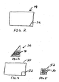
- FIG. 2 is a cross-sectional view of the vehicle HVAC system of FIG. 1 taken long line 2-2.
- FIG. 3 is an elevation view of a baffle for inclusion in the HVAC system of FIG 1 .
- FIG. 4 is a cross-sectional view of a vehicle HVAC system according to an alternative embodiment.
- FIG. 5 is an elevation view of a baffle for inclusion in the HVAC system of FIG 4 .
- a vehicle heating ventilation and air conditioning system (HVAC) 10 includes a blower motor 12, a housing 14 and a blower scroll 16.
- Blower motor 12 draws air into the system and pushes it through the HVAC system before it exits into a vehicle passenger compartment. Air exits blower scroll 16 through an outlet 18 and into a channel 20. The air then passes over evaporator 22 where it may be cooled when the HVAC system is operating in an air conditioning mode.
- channel 20 may have an increasing cross sectional area as the air flow approaches evaporator 22. This allows for a slower linear velocity of the air as it passes over the evaporator, thereby increasing residence time through the evaporator and optimizing efficiencies.
- Passage 24 may be divided by a wall 26. Air flow is directed to either side of wall 26 by a variable airflow control device, e.g., shown as temperature door 28 which pivots about pivot point 30. On one side of wall 26, all or part of the air may pass over heater core 32 where the air is warmed prior to exiting the HVAC system. Another portion or all of the air may also be directed around to bypass heater core 32 through passage 34.
- a variable airflow control device e.g., shown as temperature door 28 which pivots about pivot point 30.
- the user interface such as a knob or dial 60, located in the passenger compartment may be used to control the position of the temperature door 28, thereby effecting the portion of the air flowing over heater core 32.
- a linear relation between the position of the knob or dial and the output airflow temperature may result in a non-linear relationship.
- the inclusion of an appropriately shaped structure, such as baffle 36, at a point downstream of evaporator 22, and before the temperature door 28, can partially obstruct and direct the air flow, resulting in a more linear relationship between the knob or dial position and the output temperature.
- baffle 36 While the presence of baffle 36 may increase the lineararity of the relationship between the position of a temperature control element, such as dial 60, and the output temperature, turbulent airflow can result in vortex like patterns in the region 38 immediately downstream of baffle 36.
- cool air exiting evaporator 22 may include condensed water particles. As the air flow passes baffle 36 some of this condensed water vapor may become entrained in region 38 in the vortex like air pattern. Droplets of condensation may agglomerate and form on the downstream side of baffle 36 and migrate up to the top edge of baffle 36.
- droplets When droplets reach this point they may enter the air stream and be carried through passage 34 down to region 40 where the air streams from both sides of temperature door 28 are combined before exiting the HVAC system at outlet 42 and entering the vehicle compartment. (In some embodiments after exiting outlet 42 the air flow may be directed through additional ducting or channels to various points within the vehicle passenger compartment.) These water droplets may exit the outlet 42 in the form of a spray or mist that is not desired by vehicle occupants.
- Baffle 36 can be provided with any physical configuration that is sufficient to maintain the linearity of the temperature control device (e.g., temperature setting knob) while at the same time preventing formation of vortex like flow patterns downstream of the baffle that are significant enough to entrain water droplets.
- the baffle 36 includes apertures (46) that allow sufficient air flow through the baffle to prevent the forming of vortex like air patterns in region 38 while still obstructing enough flow to increase the linearity of the relationship between the temperature setting dial position and the output temperature.
- baffle 36 is taken along line 2-2 in FIG. 1 .
- One exemplary design of baffle 36 is shown in the lower right corner of cross-sectional area 44. While the size and shape of baffle 36 relative to cross-sectional area 44 is shown for a particular embodiment, a number of different configurations may be used, depending upon the HVAC system and the particular vehicle.
- Baffle 36 includes a plurality of apertures 46 formed therethrough. The size of apertures 46 is sufficiently large to allow enough air flow to prevent the formation of vortex like air patterns on the downstream side of baffle 36. Apertures 46 may be either circular or non-circular, preferably being between about 1 to 8 mm in diameter.
- apertures 46 may be between about 3 and 7 mm or even more preferably about 4 to 6 mm in diameter. Alternative and/or mixed aperture sizes and/or shapes may be used to optimize airflow characteristics, depending upon the specific geometry of the HVAC flow system in which the baffle is installed.
- the total cross sectional area of the apertures 46 comprises between one-tenth and one-half of the area defined by the sides of baffle 36.
- the total cross-sectional area of apertures 46 may be between one-fourth and one-third of the total area defined by the sides of baffle 36 (i.e., one-quarter to one-third of the cross sectional area of baffle 36 would be open to air flow). It has been determined that such baffles allow adequate air flow to prevent the downstream formation of vortex like air patterns while still restricting the air flow sufficiently to increase the linear relationship between the control dial or knob position and the output temperature. Optimally, vortex like air patterns are prevented to the degree that they permit the agglomeration of water droplets that could then be entrained in the airflow and be carried out of a vent and into the passenger cabin of the vehicle.
- Baffle 36 may be formed as a single unitary body with the housing of HVAC system 10 by a molding process. In such embodiments, apertures 46 may be formed during the molding process, or they may be formed by perforating baffle 36 after the housing of HVAC system 10 has been formed. Alternatively, baffle 36 may be formed separately from the housing of the HVAC system 10. In such embodiments, the apertures 46 may be formed when baffle 36 is molded or otherwise manufactured. Alternatively, apertures 46 may be formed during a separate manufacturing process. Baffle 36 may then be positioned in HVAC system by fasteners, adhesives, or other suitable means for attachment. Alternatively, if the housing of HVAC system 10 and baffle 36 are made of suitable materials, e.g., polymeric materials, baffle 36 may be coupled to the housing of HVAC system 10 by ultrasonic welding or other method.
- suitable materials e.g., polymeric materials
- cross sectional area 50 is taken along line 2-2 in FIG. 1 .
- Baffle 52 is shown in the lower right corner of cross sectional area 50. While the size and shape of baffle 52 relative to cross sectional area 50 is shown for a particular embodiment, a number of different configurations may be used depending upon the HVAC system and the particular vehicle.
- Baffle 52 includes a plurality of apertures 54 formed therethrough. The size of the apertures 54 is sufficiently large to allow enough air flow to prevent the formation of vortex like air patterns on the downstream side of baffle 52.
- the total cross sectional area of the apertures 54 comprises between one-tenth and one-half of the area defined by the sides of baffle 52.
- the total cross sectional area of apertures 54 may be between one-fourth and one-third of the total area defined by the sides of baffle 52 (i.e. one-quarter to one-third of the cross sectional area of baffle 36 would be open to air flow).
- baffle 52 i.e. one-quarter to one-third of the cross sectional area of baffle 36 would be open to air flow.
- many other shapes of baffle are possible for both baffle number 52 as well as for the apertures contained in the baffle number.
Landscapes
- Physics & Mathematics (AREA)
- Thermal Sciences (AREA)
- Engineering & Computer Science (AREA)
- Mechanical Engineering (AREA)
- Air-Conditioning For Vehicles (AREA)
Abstract
Description
- The present application relates to vehicle heating, ventilation and air conditioning (HVAC) systems. In particular, the present application relates to an air flow control member used to influence air flow through a vehicle HVAC system.
- Vehicle HVAC systems may include cabin controls that are used by a vehicle occupant to control the output temperature and airflow of the air being delivered into the vehicle cabin from the HVAC system. It may be desirable to configure an HVAC system to provide a linear relationship between the position of a temperature controller and the output temperature. For example, when the controller is in a position half way between the coldest and hottest settings, the output temperature may be about half way between the coldest and hottest output temperatures. One way of increasing the linearity of the relationship between controller position and output temperature is to position a baffle in the air flow to adjust the airflow characteristics of the system. In some systems that utilize a pivoting temperature door to direct a portion of the air flow over a heater core, a baffle may be positioned in the arc of the temperature doors travel as it moves from one setting to another.
- Such HVAC systems often drive air over an evaporator in which compressed refrigerant is flashed and have the baffle positioned downstream from the evaporator. The heat in the air is transferred to the evaporating refrigerant in the evaporator, thereby cooling the air. As the air is cooled, water in the air may condense forming small droplets, like a mist, in the air stream. When the air stream containing the small water droplets passes around a baffle, the small droplets may accumulate on the downstream side of the baffle in a region of turbulent or vortex like air flow. In this area, the small droplets may agglomerate and form larger drops as the air moves through the HVAC system. The larger drops may be carried by the air flow and out of vents into the passenger compartment of a vehicle.
- It would be advantageous to provide an HVAC system having a linear control relationship between the position of the temperature control and the output temperature.
DE 101 21 286 A1 shows a vehicle HVAC system according to the preamble of claim 1. - One embodiment of the invention relates to a vehicle HVAC system according to claim 1.
-
FIG. 1 is a schematic view of a vehicle HVAC system. -
FIG. 2 is a cross-sectional view of the vehicle HVAC system ofFIG. 1 taken long line 2-2. -
FIG. 3 is an elevation view of a baffle for inclusion in the HVAC system ofFIG 1 . -
FIG. 4 is a cross-sectional view of a vehicle HVAC system according to an alternative embodiment. -
FIG. 5 is an elevation view of a baffle for inclusion in the HVAC system ofFIG 4 . - Referring to
FIG. 1 , a vehicle heating ventilation and air conditioning system (HVAC) 10 includes ablower motor 12, ahousing 14 and a blower scroll 16.Blower motor 12 draws air into the system and pushes it through the HVAC system before it exits into a vehicle passenger compartment. Air exits blower scroll 16 through anoutlet 18 and into achannel 20. The air then passes overevaporator 22 where it may be cooled when the HVAC system is operating in an air conditioning mode. In some embodiments,channel 20 may have an increasing cross sectional area as the air flow approachesevaporator 22. This allows for a slower linear velocity of the air as it passes over the evaporator, thereby increasing residence time through the evaporator and optimizing efficiencies. After exitingevaporator 22, the air flow enterspassage 24.Passage 24 may be divided by a wall 26. Air flow is directed to either side of wall 26 by a variable airflow control device, e.g., shown astemperature door 28 which pivots aboutpivot point 30. On one side of wall 26, all or part of the air may pass overheater core 32 where the air is warmed prior to exiting the HVAC system. Another portion or all of the air may also be directed around to bypassheater core 32 throughpassage 34. - The user interface, such as a knob or
dial 60, located in the passenger compartment may be used to control the position of thetemperature door 28, thereby effecting the portion of the air flowing overheater core 32. In many vehicle applications, it is desirable to have a linear relation between the position of the knob or dial and the output airflow temperature. However, the geometries of the passageways, heater core temperature door, and other structures associated withHVAC system 10 may result in a non-linear relationship. The inclusion of an appropriately shaped structure, such asbaffle 36, at a point downstream ofevaporator 22, and before thetemperature door 28, can partially obstruct and direct the air flow, resulting in a more linear relationship between the knob or dial position and the output temperature. In some embodiments, it may be desirable to placebaffle 36 at least partially in the arc oftemperature door 28. - While the presence of
baffle 36 may increase the lineararity of the relationship between the position of a temperature control element, such asdial 60, and the output temperature, turbulent airflow can result in vortex like patterns in theregion 38 immediately downstream ofbaffle 36. WhenHVAC system 10 is operated in the air conditioning mode, coolair exiting evaporator 22 may include condensed water particles. As the air flow passes baffle 36 some of this condensed water vapor may become entrained inregion 38 in the vortex like air pattern. Droplets of condensation may agglomerate and form on the downstream side ofbaffle 36 and migrate up to the top edge ofbaffle 36. When droplets reach this point they may enter the air stream and be carried throughpassage 34 down toregion 40 where the air streams from both sides oftemperature door 28 are combined before exiting the HVAC system atoutlet 42 and entering the vehicle compartment. (In some embodiments after exitingoutlet 42 the air flow may be directed through additional ducting or channels to various points within the vehicle passenger compartment.) These water droplets may exit theoutlet 42 in the form of a spray or mist that is not desired by vehicle occupants. - Baffle 36 can be provided with any physical configuration that is sufficient to maintain the linearity of the temperature control device (e.g., temperature setting knob) while at the same time preventing formation of vortex like flow patterns downstream of the baffle that are significant enough to entrain water droplets. According to the invention, the
baffle 36 includes apertures (46) that allow sufficient air flow through the baffle to prevent the forming of vortex like air patterns inregion 38 while still obstructing enough flow to increase the linearity of the relationship between the temperature setting dial position and the output temperature. - Referring to
FIGS. 2 and 3 , cross-sectional area 44 is taken along line 2-2 inFIG. 1 . One exemplary design ofbaffle 36 is shown in the lower right corner of cross-sectional area 44. While the size and shape ofbaffle 36 relative to cross-sectional area 44 is shown for a particular embodiment, a number of different configurations may be used, depending upon the HVAC system and the particular vehicle. Baffle 36 includes a plurality ofapertures 46 formed therethrough. The size ofapertures 46 is sufficiently large to allow enough air flow to prevent the formation of vortex like air patterns on the downstream side ofbaffle 36.Apertures 46 may be either circular or non-circular, preferably being between about 1 to 8 mm in diameter. More preferably,apertures 46 may be between about 3 and 7 mm or even more preferably about 4 to 6 mm in diameter. Alternative and/or mixed aperture sizes and/or shapes may be used to optimize airflow characteristics, depending upon the specific geometry of the HVAC flow system in which the baffle is installed. - According to the invention, the total cross sectional area of the
apertures 46 comprises between one-tenth and one-half of the area defined by the sides ofbaffle 36. Preferably, the total cross-sectional area ofapertures 46 may be between one-fourth and one-third of the total area defined by the sides of baffle 36 (i.e., one-quarter to one-third of the cross sectional area ofbaffle 36 would be open to air flow). It has been determined that such baffles allow adequate air flow to prevent the downstream formation of vortex like air patterns while still restricting the air flow sufficiently to increase the linear relationship between the control dial or knob position and the output temperature. Optimally, vortex like air patterns are prevented to the degree that they permit the agglomeration of water droplets that could then be entrained in the airflow and be carried out of a vent and into the passenger cabin of the vehicle. -
Baffle 36 may be formed as a single unitary body with the housing ofHVAC system 10 by a molding process. In such embodiments,apertures 46 may be formed during the molding process, or they may be formed by perforatingbaffle 36 after the housing ofHVAC system 10 has been formed. Alternatively,baffle 36 may be formed separately from the housing of theHVAC system 10. In such embodiments, theapertures 46 may be formed whenbaffle 36 is molded or otherwise manufactured. Alternatively,apertures 46 may be formed during a separate manufacturing process.Baffle 36 may then be positioned in HVAC system by fasteners, adhesives, or other suitable means for attachment. Alternatively, if the housing ofHVAC system 10 and baffle 36 are made of suitable materials, e.g., polymeric materials, baffle 36 may be coupled to the housing ofHVAC system 10 by ultrasonic welding or other method. - Referring to
FIGS. 4 and 5 , crosssectional area 50 is taken along line 2-2 inFIG. 1 .Baffle 52 is shown in the lower right corner of crosssectional area 50. While the size and shape ofbaffle 52 relative to crosssectional area 50 is shown for a particular embodiment, a number of different configurations may be used depending upon the HVAC system and the particular vehicle.Baffle 52 includes a plurality ofapertures 54 formed therethrough. The size of theapertures 54 is sufficiently large to allow enough air flow to prevent the formation of vortex like air patterns on the downstream side ofbaffle 52. The total cross sectional area of theapertures 54 comprises between one-tenth and one-half of the area defined by the sides ofbaffle 52. In other embodiments, the total cross sectional area ofapertures 54 may be between one-fourth and one-third of the total area defined by the sides of baffle 52 (i.e. one-quarter to one-third of the cross sectional area ofbaffle 36 would be open to air flow). Obviously, many other shapes of baffle are possible for bothbaffle number 52 as well as for the apertures contained in the baffle number. - Although the foregoing has been described with reference to exemplary embodiments, workers skilled in the art will recognize that changes may be made in form and detail without departing from the scope of the appended claims. The scope of these and other changes will become apparent from the appended claims.
Claims (3)
- A vehicle HVAC system comprising an evaporator (22), a heater core (32), a variable airflow control device (28), and a baffle (36, 52), wherein the baffle comprises a geometrical configuration sufficient to prevent the formation of vortex like airflow patterns near a downstream side of the baffle, when the HVAC system is in use, such that the variable airflow control device (28) comprises a pivoting temperature door, and the baffle is placed proximate to an arc of travel traced by the temperature door as it moves from one position to another, wherein the baffle (36, 52) comprises a plate member containing a plurality of apertures and wherein the apertures (46, 54) comprise about one-tenth to one-half, particularly one-fourth to one-third of the cross-sectional area of the baffle
characterized in that the baffle is located in a corner of the cross sectional area of the housing of the HVAC system. - The HVAC system of claim 1, wherein the apertures (46, 54) have an average diameter between about 2 and 8 mm, particularly between about 3 and 7 mm.
- The HVAC system of any of the preceding claims, wherein the baffle plate member has an approximately triangular shape.
Applications Claiming Priority (1)
| Application Number | Priority Date | Filing Date | Title |
|---|---|---|---|
| US11/898,064 US7997096B2 (en) | 2007-09-07 | 2007-09-07 | Baffle for HVAC systems |
Publications (2)
| Publication Number | Publication Date |
|---|---|
| EP2033822A1 EP2033822A1 (en) | 2009-03-11 |
| EP2033822B1 true EP2033822B1 (en) | 2013-11-20 |
Family
ID=40076810
Family Applications (1)
| Application Number | Title | Priority Date | Filing Date |
|---|---|---|---|
| EP08015801.7A Ceased EP2033822B1 (en) | 2007-09-07 | 2008-09-08 | Baffle for HVAC systems |
Country Status (2)
| Country | Link |
|---|---|
| US (1) | US7997096B2 (en) |
| EP (1) | EP2033822B1 (en) |
Families Citing this family (7)
| Publication number | Priority date | Publication date | Assignee | Title |
|---|---|---|---|---|
| JP6281362B2 (en) * | 2014-03-26 | 2018-02-21 | 株式会社デンソー | Air conditioning unit for vehicles |
| JP6221890B2 (en) * | 2014-03-26 | 2017-11-01 | 株式会社デンソー | Air conditioning unit for vehicles |
| DE102015200942A1 (en) * | 2015-01-21 | 2016-07-21 | Mahle International Gmbh | Air conditioning with a spoiler |
| JP2019156115A (en) * | 2018-03-12 | 2019-09-19 | 株式会社ケーヒン | Air conditioner for vehicle |
| US10704574B2 (en) | 2018-08-31 | 2020-07-07 | Denso International America, Inc. | HVAC airflow baffle |
| US11460250B2 (en) * | 2020-06-30 | 2022-10-04 | Rivian Ip Holdings, Llc | Dryer attachment for a vehicle |
| US20260097622A1 (en) * | 2024-10-04 | 2026-04-09 | Valeo Systemes Thermiques | Heating, ventilation, and air conditioning system |
Family Cites Families (23)
| Publication number | Priority date | Publication date | Assignee | Title |
|---|---|---|---|---|
| US1865775A (en) | 1931-08-27 | 1932-07-05 | Sr Joseph A Martocello | Water distributor for condensers of ice manufacturing systems |
| US4083198A (en) | 1976-03-29 | 1978-04-11 | Dennis Donald I | Air conditioner case with condensation shield |
| DE7739556U1 (en) | 1977-12-24 | 1979-04-19 | Voith Getriebe Kg, 7920 Heidenheim | Short diffuser |
| DE4336822A1 (en) | 1993-10-28 | 1995-05-04 | Behr Gmbh & Co | Mist collector for evaporator in motor-vehicle air-conditioning systems |
| DE4338099C2 (en) | 1993-11-08 | 1996-01-25 | Daimler Benz Ag | Device for supplying air to the passenger compartment of vehicles |
| DE4408796A1 (en) | 1994-03-15 | 1995-09-21 | Behr Gmbh & Co | Air drying system for motor vehicles |
| FR2780347B1 (en) | 1998-06-29 | 2001-02-23 | Valeo Climatisation | MOTOR VEHICLE HEATING AND / OR AIR CONDITIONING BOX WITH IMPROVED ACOUSTIC PERFORMANCE |
| EP1101640B1 (en) | 1999-11-22 | 2006-04-26 | Calsonic Kansei Corporation | Automotive air conditioning unit |
| US6692223B2 (en) * | 2000-09-29 | 2004-02-17 | Mitsubishi Denki Kabushiki Kaisha | Air conditioner |
| DE10121286A1 (en) | 2001-04-30 | 2002-10-31 | Valeo Klimasysteme Gmbh | Air duct, for a motor vehicle air conditioning system, is provided with at least one plate which has a definite pattern of holes and covers the cross section of at least one air flow channel |
| JP4388243B2 (en) | 2001-06-27 | 2009-12-24 | 三菱重工業株式会社 | Air conditioner for vehicles |
| DE10135778A1 (en) | 2001-07-23 | 2003-02-13 | Bayerische Motoren Werke Ag | Motor vehicle with separator to remove water from air flow into passenger space has housing with vertical dividing wall of air-permeable moisture-resistant material to collect water, and water removal device |
| JP4508483B2 (en) * | 2001-07-25 | 2010-07-21 | 三菱重工業株式会社 | Air conditioner for vehicles |
| DE10147759A1 (en) | 2001-09-27 | 2003-04-10 | Behr Gmbh & Co | Condensed water separator, has grid with channels on side remote from evaporator and contacts essentially horizontal lines of evaporator with rear side of part of channels |
| US6729152B2 (en) | 2001-10-24 | 2004-05-04 | Carrier Corporation | Thermal shield for evaporator with plastic outer covering |
| DE20217506U1 (en) | 2002-11-13 | 2003-01-16 | Reum GmbH & Co. Betriebs KG, 74736 Hardheim | Air guiding device for the interior of vehicles |
| JP2004268705A (en) * | 2003-03-07 | 2004-09-30 | Denso Corp | Vehicle air conditioner |
| DE20309978U1 (en) | 2003-06-27 | 2003-09-04 | Sarnatech Paulmann & Crone GmbH, 58509 Lüdenscheid | Diffusor for motor vehicle air conditioning has housing with manual adjuster wheel operating pivoting flap to control airflow |
| KR20050029478A (en) | 2003-09-23 | 2005-03-28 | 현대자동차주식회사 | Evaporator core for vehicle |
| JP2005289152A (en) * | 2004-03-31 | 2005-10-20 | Calsonic Kansei Corp | Air-conditioning control device |
| DE102004017616A1 (en) | 2004-04-07 | 2005-10-27 | Behr Gmbh & Co. Kg | Evaporator for motor vehicle air conditioning system, has grid that is connected with evaporator by soldering or welding, where grid has undulated shape and undulations are arranged in vertical direction |
| JP4353053B2 (en) * | 2004-10-04 | 2009-10-28 | 株式会社デンソー | Air conditioner for vehicles |
| JP4395796B2 (en) * | 2007-07-10 | 2010-01-13 | 株式会社デンソー | Air conditioner for vehicles |
-
2007
- 2007-09-07 US US11/898,064 patent/US7997096B2/en not_active Expired - Fee Related
-
2008
- 2008-09-08 EP EP08015801.7A patent/EP2033822B1/en not_active Ceased
Also Published As
| Publication number | Publication date |
|---|---|
| US7997096B2 (en) | 2011-08-16 |
| US20090064694A1 (en) | 2009-03-12 |
| EP2033822A1 (en) | 2009-03-11 |
Similar Documents
| Publication | Publication Date | Title |
|---|---|---|
| US7997096B2 (en) | Baffle for HVAC systems | |
| CN105189162B (en) | air blower | |
| EP1241032B1 (en) | Automotive air conditioner | |
| US20070111652A1 (en) | Air vent, especially for a motor vehicle | |
| EP1787836B1 (en) | Vehicular air conditioner | |
| JP2007168642A (en) | Air conditioner for vehicles | |
| JP6356019B2 (en) | Air conditioner for vehicles | |
| US20020104330A1 (en) | Air-conditioning device for a motor vehicle | |
| US6568200B2 (en) | Air-conditioning system for a vehicle | |
| US9145041B2 (en) | Air mixing apparatus for HVAC system | |
| JP2009143338A (en) | Air conditioner for vehicles | |
| JP5924230B2 (en) | Air conditioner | |
| KR101709981B1 (en) | Air conditioning system for automotive vehicles | |
| KR20210008401A (en) | A housing to be mounted on an automobile door, and a door comprising such a housing | |
| JP2005306166A (en) | Air conditioner for vehicles | |
| CN210116357U (en) | Air conditioning assembly for vehicle and vehicle having the same | |
| JP4341171B2 (en) | Air conditioner for vehicles | |
| JP2013052808A (en) | Device for reducing aerodynamic sound | |
| JP5098940B2 (en) | Air conditioner for vehicles | |
| JP5098590B2 (en) | Air conditioner for vehicles | |
| EP1826039B1 (en) | Variable flow valve | |
| JP3447721B2 (en) | Vehicle air conditioner | |
| KR101495716B1 (en) | Air conditioning system for automotive vehicles | |
| JP2006082780A (en) | Air-conditioning unit and vehicular air-conditioner | |
| US20070131407A1 (en) | Air conditioning apparatus |
Legal Events
| Date | Code | Title | Description |
|---|---|---|---|
| PUAI | Public reference made under article 153(3) epc to a published international application that has entered the european phase |
Free format text: ORIGINAL CODE: 0009012 |
|
| AK | Designated contracting states |
Kind code of ref document: A1 Designated state(s): AT BE BG CH CY CZ DE DK EE ES FI FR GB GR HR HU IE IS IT LI LT LU LV MC MT NL NO PL PT RO SE SI SK TR |
|
| AX | Request for extension of the european patent |
Extension state: AL BA MK RS |
|
| 17P | Request for examination filed |
Effective date: 20090911 |
|
| 17Q | First examination report despatched |
Effective date: 20091005 |
|
| AKX | Designation fees paid |
Designated state(s): DE FR |
|
| REG | Reference to a national code |
Ref country code: DE Ref legal event code: R079 Ref document number: 602008028782 Country of ref document: DE Free format text: PREVIOUS MAIN CLASS: B60H0001000000 Ipc: B60H0001320000 |
|
| GRAP | Despatch of communication of intention to grant a patent |
Free format text: ORIGINAL CODE: EPIDOSNIGR1 |
|
| RIC1 | Information provided on ipc code assigned before grant |
Ipc: B60H 1/00 20060101ALI20121126BHEP Ipc: B60H 1/32 20060101AFI20121126BHEP |
|
| GRAS | Grant fee paid |
Free format text: ORIGINAL CODE: EPIDOSNIGR3 |
|
| GRAP | Despatch of communication of intention to grant a patent |
Free format text: ORIGINAL CODE: EPIDOSNIGR1 |
|
| INTG | Intention to grant announced |
Effective date: 20130709 |
|
| GRAA | (expected) grant |
Free format text: ORIGINAL CODE: 0009210 |
|
| AK | Designated contracting states |
Kind code of ref document: B1 Designated state(s): DE FR |
|
| REG | Reference to a national code |
Ref country code: DE Ref legal event code: R096 Ref document number: 602008028782 Country of ref document: DE Effective date: 20140116 |
|
| REG | Reference to a national code |
Ref country code: DE Ref legal event code: R097 Ref document number: 602008028782 Country of ref document: DE |
|
| PLBE | No opposition filed within time limit |
Free format text: ORIGINAL CODE: 0009261 |
|
| STAA | Information on the status of an ep patent application or granted ep patent |
Free format text: STATUS: NO OPPOSITION FILED WITHIN TIME LIMIT |
|
| 26N | No opposition filed |
Effective date: 20140821 |
|
| REG | Reference to a national code |
Ref country code: DE Ref legal event code: R097 Ref document number: 602008028782 Country of ref document: DE Effective date: 20140821 |
|
| REG | Reference to a national code |
Ref country code: DE Ref legal event code: R082 Ref document number: 602008028782 Country of ref document: DE Representative=s name: GRAUEL, ANDREAS, DIPL.-PHYS. DR. RER. NAT., DE |
|
| REG | Reference to a national code |
Ref country code: DE Ref legal event code: R081 Ref document number: 602008028782 Country of ref document: DE Owner name: MAHLE BEHR USA INC., TROY, US Free format text: FORMER OWNER: BEHR AMERICA, INC., TROY, MICH., US Effective date: 20150408 Ref country code: DE Ref legal event code: R082 Ref document number: 602008028782 Country of ref document: DE Representative=s name: GRAUEL, ANDREAS, DIPL.-PHYS. DR. RER. NAT., DE Effective date: 20150408 Ref country code: DE Ref legal event code: R081 Ref document number: 602008028782 Country of ref document: DE Owner name: MAHLE INTERNATIONAL GMBH, DE Free format text: FORMER OWNER: BEHR AMERICA, INC., TROY, MICH., US Effective date: 20150408 |
|
| REG | Reference to a national code |
Ref country code: DE Ref legal event code: R082 Ref document number: 602008028782 Country of ref document: DE Representative=s name: GRAUEL, ANDREAS, DIPL.-PHYS. DR. RER. NAT., DE Ref country code: DE Ref legal event code: R081 Ref document number: 602008028782 Country of ref document: DE Owner name: MAHLE INTERNATIONAL GMBH, DE Free format text: FORMER OWNER: MAHLE BEHR USA INC., TROY, MICH., US |
|
| REG | Reference to a national code |
Ref country code: FR Ref legal event code: PLFP Year of fee payment: 9 |
|
| REG | Reference to a national code |
Ref country code: FR Ref legal event code: PLFP Year of fee payment: 10 |
|
| REG | Reference to a national code |
Ref country code: FR Ref legal event code: PLFP Year of fee payment: 11 |
|
| PGFP | Annual fee paid to national office [announced via postgrant information from national office to epo] |
Ref country code: FR Payment date: 20180924 Year of fee payment: 11 |
|
| PGFP | Annual fee paid to national office [announced via postgrant information from national office to epo] |
Ref country code: DE Payment date: 20181001 Year of fee payment: 11 |
|
| REG | Reference to a national code |
Ref country code: DE Ref legal event code: R119 Ref document number: 602008028782 Country of ref document: DE |
|
| PG25 | Lapsed in a contracting state [announced via postgrant information from national office to epo] |
Ref country code: DE Free format text: LAPSE BECAUSE OF NON-PAYMENT OF DUE FEES Effective date: 20200401 |
|
| PG25 | Lapsed in a contracting state [announced via postgrant information from national office to epo] |
Ref country code: FR Free format text: LAPSE BECAUSE OF NON-PAYMENT OF DUE FEES Effective date: 20190930 |