EP2033795A1 - Printing apparatus - Google Patents
Printing apparatus Download PDFInfo
- Publication number
- EP2033795A1 EP2033795A1 EP08290642A EP08290642A EP2033795A1 EP 2033795 A1 EP2033795 A1 EP 2033795A1 EP 08290642 A EP08290642 A EP 08290642A EP 08290642 A EP08290642 A EP 08290642A EP 2033795 A1 EP2033795 A1 EP 2033795A1
- Authority
- EP
- European Patent Office
- Prior art keywords
- pallet
- unit
- pair
- anteroposterior
- station unit
- Prior art date
- Legal status (The legal status is an assumption and is not a legal conclusion. Google has not performed a legal analysis and makes no representation as to the accuracy of the status listed.)
- Granted
Links
- 238000007639 printing Methods 0.000 title claims abstract description 101
- 230000007246 mechanism Effects 0.000 claims abstract description 138
- 239000000758 substrate Substances 0.000 claims abstract description 78
- 238000012805 post-processing Methods 0.000 description 43
- 238000001035 drying Methods 0.000 description 34
- 239000000976 ink Substances 0.000 description 29
- 238000007781 pre-processing Methods 0.000 description 23
- 238000012545 processing Methods 0.000 description 10
- 239000000463 material Substances 0.000 description 8
- 238000000034 method Methods 0.000 description 8
- 230000009471 action Effects 0.000 description 5
- 238000012423 maintenance Methods 0.000 description 5
- 230000008569 process Effects 0.000 description 5
- 239000011248 coating agent Substances 0.000 description 4
- 238000000576 coating method Methods 0.000 description 4
- 239000011253 protective coating Substances 0.000 description 4
- 239000003086 colorant Substances 0.000 description 3
- 230000000149 penetrating effect Effects 0.000 description 3
- 238000007650 screen-printing Methods 0.000 description 3
- 230000008602 contraction Effects 0.000 description 2
- 230000002093 peripheral effect Effects 0.000 description 2
- 238000003825 pressing Methods 0.000 description 2
- 239000004744 fabric Substances 0.000 description 1
- 238000004519 manufacturing process Methods 0.000 description 1
- 238000012986 modification Methods 0.000 description 1
- 230000004048 modification Effects 0.000 description 1
- 230000009467 reduction Effects 0.000 description 1
Images




Classifications
-
- B—PERFORMING OPERATIONS; TRANSPORTING
- B41—PRINTING; LINING MACHINES; TYPEWRITERS; STAMPS
- B41J—TYPEWRITERS; SELECTIVE PRINTING MECHANISMS, i.e. MECHANISMS PRINTING OTHERWISE THAN FROM A FORME; CORRECTION OF TYPOGRAPHICAL ERRORS
- B41J3/00—Typewriters or selective printing or marking mechanisms characterised by the purpose for which they are constructed
- B41J3/28—Typewriters or selective printing or marking mechanisms characterised by the purpose for which they are constructed for printing downwardly on flat surfaces, e.g. of books, drawings, boxes, envelopes, e.g. flat-bed ink-jet printers
-
- B—PERFORMING OPERATIONS; TRANSPORTING
- B41—PRINTING; LINING MACHINES; TYPEWRITERS; STAMPS
- B41F—PRINTING MACHINES OR PRESSES
- B41F15/00—Screen printers
- B41F15/14—Details
- B41F15/16—Printing tables
- B41F15/18—Supports for workpieces
- B41F15/26—Supports for workpieces for articles with flat surfaces
-
- B—PERFORMING OPERATIONS; TRANSPORTING
- B41—PRINTING; LINING MACHINES; TYPEWRITERS; STAMPS
- B41F—PRINTING MACHINES OR PRESSES
- B41F15/00—Screen printers
- B41F15/02—Manually-operable devices
- B41F15/04—Manually-operable devices for multicolour printing
-
- B—PERFORMING OPERATIONS; TRANSPORTING
- B41—PRINTING; LINING MACHINES; TYPEWRITERS; STAMPS
- B41F—PRINTING MACHINES OR PRESSES
- B41F15/00—Screen printers
- B41F15/08—Machines
- B41F15/10—Machines for multicolour printing
-
- B—PERFORMING OPERATIONS; TRANSPORTING
- B41—PRINTING; LINING MACHINES; TYPEWRITERS; STAMPS
- B41J—TYPEWRITERS; SELECTIVE PRINTING MECHANISMS, i.e. MECHANISMS PRINTING OTHERWISE THAN FROM A FORME; CORRECTION OF TYPOGRAPHICAL ERRORS
- B41J11/00—Devices or arrangements of selective printing mechanisms, e.g. ink-jet printers or thermal printers, for supporting or handling copy material in sheet or web form
- B41J11/02—Platens
- B41J11/06—Flat page-size platens or smaller flat platens having a greater size than line-size platens
-
- B—PERFORMING OPERATIONS; TRANSPORTING
- B41—PRINTING; LINING MACHINES; TYPEWRITERS; STAMPS
- B41J—TYPEWRITERS; SELECTIVE PRINTING MECHANISMS, i.e. MECHANISMS PRINTING OTHERWISE THAN FROM A FORME; CORRECTION OF TYPOGRAPHICAL ERRORS
- B41J3/00—Typewriters or selective printing or marking mechanisms characterised by the purpose for which they are constructed
- B41J3/407—Typewriters or selective printing or marking mechanisms characterised by the purpose for which they are constructed for marking on special material
- B41J3/4078—Printing on textile
-
- Y—GENERAL TAGGING OF NEW TECHNOLOGICAL DEVELOPMENTS; GENERAL TAGGING OF CROSS-SECTIONAL TECHNOLOGIES SPANNING OVER SEVERAL SECTIONS OF THE IPC; TECHNICAL SUBJECTS COVERED BY FORMER USPC CROSS-REFERENCE ART COLLECTIONS [XRACs] AND DIGESTS
- Y10—TECHNICAL SUBJECTS COVERED BY FORMER USPC
- Y10S—TECHNICAL SUBJECTS COVERED BY FORMER USPC CROSS-REFERENCE ART COLLECTIONS [XRACs] AND DIGESTS
- Y10S428/00—Stock material or miscellaneous articles
- Y10S428/914—Transfer or decalcomania
Definitions
- the present invention relates to a printing apparatus for printing intended characters, images etc. on a print substrate such as a T-shirt by sequentially conducting a plurality of processing operations.
- a preprocessing for the purpose of preventing ink blurring and an post-processing for the purpose of protecting images printed on the surface of the print substrate.
- an apparatus of a type that print substrates are conveyed by a conveying means such as a belt conveyer In this case, a pallet is put on a conveying member such as conveyer belt and the print substrates are placed and held at predetermined positions on the pallet. In this state, the print substrates are conveyed together with the pallet and stopped at every working position where various working devices are placed so that print substrates are processed according to the processing steps such as the aforementioned preprocessing.
- the conveying means such as a belt conveyer and a predetermined printing process is carried out relative to the print substrates on the pallet being conveyed
- it is only allowed to conduct relatively rough printing without requiring high precision and it is difficult to conduct printing requiring high precision because of variation in speed and generation of vibration during the conveyance. Therefore, there is an idea to fix the pallet at a predetermined working position on the conveying member such as a conveyer belt where a predetermined printing process is conducted relative to the print substrates.
- a moving mechanism for moving a working device such as a printer head having a plurality of inkjet nozzles forward, backward, leftward, and rightward above the fixed print substrates.
- the present invention is made to address the aforementioned problems and it is an object of the present invention to provide a printing apparatus in which a moving mechanism for moving a working device forward, backward, leftward, and rightward above print substrates is arranged without interrupting the passage of a pallet.
- a printing apparatus comprising:
- a printing apparatus for example, the printing apparatus 1 of the embodiment
- a printing apparatus comprises: a pallet (for example, the pallet 6 in the embodiment) on which a print substrate (for example, print substrates 5 in the embodiment) is placed; a conveyer system (for example, the conveyer unit 10 in the embodiment) for conveying said pallet, having an upper conveying passage (for example, the upper conveyer mechanism 11 in the embodiment) and a lower conveying passage (for example, the lower conveyer mechanism 12 in the embodiment) which are arranged in two stages in the vertical direction; a pair of left and right anteroposterior moving mechanisms (for example, the anteroposterior moving mechanisms 220, 230 in the embodiment) which are arranged on left and right sides of the upper conveying passage and extend in the anteroposterior direction; a pair of left and right fitting members (for example, the fitting members 240, 245 in the embodiment) which are disposed on the pair of left and right anteroposterior moving mechanisms, respectively and are
- the anteroposterior moving mechanisms comprise: a pair of left and right first driven sprockets and a pair of left and right second driven sprockets which are arranged on left and right sides of the upper conveying passage and which are rotatably disposed to be spaced apart from each other in the anteroposterior direction; a pair of left and right driving sprockets which are rotatably disposed below the second driven sprockets; a driving shaft which is disposed below the lower conveying passage and extends in the lateral direction to connect the pair of left and right driving sprockets; a driving device which is disposed below the lower conveying passage to rotate the driving shaft; and a pair of left and right endless moving members each of which is formed in a ring shape via each fitting member and each of which is wound around and each first driven sprocket, each second driven sprocket, and each driving sprocket to extend around them.
- the fitting members are moved in synchronism with each other via the endless moving members, which are formed in an L-like shape and arranged on left and right sides of the conveyer system, so as to move the head device in the anteroposterior direction together with the guide bar member.
- the driving device and the driving shaft composing the anteroposterior moving mechanisms are arranged below the lower conveying passages, it is possible to dispose the anteroposterior moving mechanism not to interrupt the passage of the pallet.
- Fig. 1 shows a schematic structure of a printing apparatus 1 according to an embodiment of the present invention.
- the printing apparatus 1 comprises eight work station units (a loading station unit 2a, a preprocessing station unit 2b, a first drying station unit 2c, an undercoating station unit 2d, a printing station unit 2e, an post-processing station unit 2f, a second drying station unit 2g, and a collecting station unit 2h) which are aligned adjacent to each other.
- work station units a loading station unit 2a, a preprocessing station unit 2b, a first drying station unit 2c, an undercoating station unit 2d, a printing station unit 2e, an post-processing station unit 2f, a second drying station unit 2g, and a collecting station unit 2h
- the station units 2b through 2g are provided corresponding to respective processing operations to be conducted to a print substrate 5 such as T-shirts and each comprise a work unit (a preprocessing unit 3b, a drying unit 3c, 3g, an undercoating unit 3d, a printing unit 3e, an post-processing unit 3f) for conducting each processing operation.
- a work unit a preprocessing unit 3b, a drying unit 3c, 3g, an undercoating unit 3d, a printing unit 3e, an post-processing unit 3f
- Each of the station units 2b through 2g has a conveyer unit 10 for conveying a pallet 6 which holds the print substrate 5 thereon.
- the conveyer unit 10 comprises an upper conveyer mechanism 11 for conveying the pallet 6 holding the print substrate 5 thereon at a working position as will be described later for each work unit (the preprocessing unit 3b, the drying unit 3c, 3g, the undercoating unit 3d, the printing unit 3e, the post-processing unit 3f), and a lower conveyer mechanism 12 for conveying the empty pallet 6 (without holding the print substrate 5).
- the upper conveyer mechanisms 11 and the lower conveyer mechanisms 12 are placed in a uniform way through the respective station units 2b through 2g such that ends as the pallet receiving portions and the pallet let-off portions of the respective upper conveyer mechanisms 11 are surely abutted to each other and also ends as the pallet receiving portions and the pallet let-off portions of the respective lower conveyer mechanisms 12 are surely abutted to each other so as to allow the delivery of the pallet 6 between the station units.
- the loading station unit 2a and the collecting station unit 2h each have an elevation unit 13, 13 for carrying the pallet 6 between the upper conveyer mechanism 11 and the lower conveyer mechanism 12.
- the elevation unit 13, 13 moves up and down to abut itself to the ends as the pallet receiving portion and the pallet let-off portion of the upper conveyer mechanism 11 and the lower conveyer mechanism 12 so as to allow the delivery of the pallet 6 between the upper conveyer mechanism 11 and the lower conveyer mechanism 12.
- the pallet 6 can be conveyed and circulated through the respective station units 2a through 2h by the elevation units 13, 13 and the upper and lower conveyer mechanisms 11, 12 (the respective conveyer units 10).
- each elevation unit 13, 13 or each work unit (the preprocessing unit 3b, the drying unit 3c, 3g, the undercoating unit 3d, the printing unit 3e, the post-processing unit 3f) and each conveyer unit 10 are mounted to a frame body (a conveyer frame 130, an elevation frame 152 in Fig. 2 ) of each station unit and thus can be replaced or rearranged integrally with each frame body.
- Each frame body has wheels 14 (wheels 131 a, wheels 151 in Fig. 2 ) which are fixed to the bottom thereof and have locking mechanisms, respectively, thereby easily allowing the movement of each of the station units 2a through 2h.
- a print substrate 5 is first put on the pallet 6 by an operator in the loading station unit 2a.
- the pallet 6 holding the print substrate 5 thereon is moved by the elevation unit 13 toward the upper conveyer mechanism 11 of the preprocessing station unit 2b and is then conveyed to the next station unit i.e. the preprocessing station unit 2b.
- the preprocessing station unit 2b comprises the preprocessing unit 3b having a preprocessing printer or the like for conducting a preprocessing step by applying base coating material (transparent ink) to the surface of the print substrate 5 (in a range where intended characters, images, etc. are printed) to previously coat the surface of the print substrate 5.
- the preprocessing step is conducted for the purpose of preventing ejected inks, applied at the undercoating station unit 2d and the printing station unit 2e, from penetrating inside the print substrate 5 and preventing ink blurring.
- the pallet 6 conveyed from the loading station unit 2a to the preprocessing station unit 2b is moved to a working position, as will be described later, of the preprocessing unit 3b via a standby position, as will be described later, by the upper conveyer mechanism 11.
- the print substrate 5 on the pallet 6 is subjected to the aforementioned preprocessing step while the pallet 6 is held at the working position and is then conveyed to the next station unit i.e. the first drying station unit 2c.
- the first drying station unit 2c comprises the drying unit 3c having a heater or the like for drying the base coating material (transparent ink) which was applied at the preprocessing station unit 2b (the preprocessing unit 3b) to coat the surface of the print substrate 5.
- the drying step is conducted for the purpose of preventing adhesion of inks applied at the undercoating station unit 2d and the printing station unit 2e from being poor and thus preventing the print quality from being poor.
- the pallet 6 conveyed from the preprocessing station unit 2b to the first drying station unit 2c is moved to a working position of the drying unit 3c via a standby position by the upper conveyer mechanism 11.
- the print substrate 5 on the pallet 6 is subjected to the aforementioned drying step while the pallet 6 is held at the working position and is then conveyed to the next station unit i.e. the undercoating station unit 2d.
- the undercoating station unit 2d comprises the undercoating unit 3d having an undercoat printer or the like for conducting an undercoating process by applying undercoating material (white ink) on the surface (the surface of the base coating material) of the print substrate 5 preprocessed at the preprocessing station unit 2b (the preprocessing unit 3b).
- the undercoating process allows the intended color characters, images, etc. to be printed without affecting the color of ink ejected at the printing station unit 2e by the color of the print substrate 5 itself, thereby improving the chromogenic characteristics.
- the pallet 6 conveyed from the first drying station unit 2c to the undercoating station unit 2d is moved to a working position of the undercoating unit 3d via a standby position by the upper conveyer mechanism 11.
- the print substrate 5 on the pallet 6 is subjected to the aforementioned undercoating process while the pallet 6 is held at the working position and is then conveyed to the next station unit i.e. the printing station unit 2e.
- the printing station unit 2e comprises a printing unit 3e having an inkjet printer or the like for conducting a printing step for printing intended characters, images, etc. by ejecting ink droplets from inkjet nozzle onto the surface of the print substrate 5 undercoated at the undercoating station unit 2d (the undercoating unit 3d).
- the pallet 6 conveyed from the undercoating station unit 2d to the printing station unit 2e is moved to a working position of the printing unit 3e via a standby position by the upper conveyer mechanism 11.
- the print substrate 5 on the pallet 6 is subjected to the aforementioned printing step while the pallet 6 is held at the working position and is then conveyed to the next station unit i.e. the post-processing station unit 2f.
- the post-processing station unit 2f comprises the post-processing unit 3f having an post-processing printer or the like for conducting an post-processing step by applying protective coating material (transparent ink) to the surface of the characters, images, etc. of the print substrate 5 printed at the printing station unit 2e (the printing unit 3e) to protect and coat the surface.
- protective coating material transparent ink
- the post-processing step is conducted for the purpose of preventing the ejected ink of the intended characters, images, etc. printed at the printing station unit 2e (the printing unit 3e) from peeling off the surface of the print substrate 5.
- the pallet 6 conveyed from the printing station unit 2e to the post-processing station unit 2f is moved to a working position of the post-processing unit 3f via a standby position by the upper conveyer mechanism 11.
- the print substrate 5 on the pallet 6 is subjected to the aforementioned post-processing step while the pallet 6 is held at the working position and is then conveyed to the next station unit i.e. the second drying station unit 2g.
- the second drying station unit 2g comprises the drying unit 3g having a heater or the like for drying the protective coating material (transparent ink) protecting and coating the surface of the printed characters, images, etc. of the print substrate 5 applied at the post-processing station unit 2f (the post-processing unit 3f).
- the pallet 6 conveyed from the post-processing station unit 2f to the second drying station unit 2g is moved to a working position of the drying unit 3g via a standby position by the upper conveyer mechanism 11.
- the print substrate 5 on the pallet 6 is subjected to the aforementioned drying step while the pallet 6 is held at the working position and is then conveyed to the next station unit i.e. the collecting station unit 2h.
- the finished print substrate 5 on the pallet 6 conveyed from the second drying station unit 2g after the respective processing operations is collected by the operator.
- Empty pallet 6 after the print substrate 5 is collected is moved by the elevation unit 13 toward the lower conveyer mechanism 12 of the second drying station unit 2g and is conveyed to the loading station unit 2a through the post-processing station unit 2f, the printing station unit 2e, the undercoating station unit 2d, the first drying station unit 2c, and the preprocessing station unit 2b in this order by the lower conveyer mechanisms 12.
- a new print substrate 5 is put on the empty pallet 6 and is subjected to the aforementioned steps.
- FIG. 2 shows a printing apparatus 1' comprising a loading station unit 2a, a printing station unit 2e, and a collecting station unit 2h which are aligned adjacent to each other.
- directions indicated by arrows "UP”, “FRONT”, AND “LEFT” will be upward, forward, and leftward directions in the following description.
- the printing station unit 2e comprises a conveyer unit 10 which is composed of an upper conveyer mechanism 11 for conveying a pallet 6 holding a print substrate 5 thereon, a lower conveyer mechanism 12, and a printer unit 20 (a printing unit 3e) as will be described later.
- the pallet 6 is formed into a rectangular plate-shape and has a pair of long table supporting members 7, 7 fixed to the upper surface thereof. Disposed on the table supporting members 7, 7 are a plurality of (four in this embodiment) loading tables 8 which are aligned in the lateral direction.
- Each loading table 8 comprises a top panel 8a having a rectangular plate shape for holding each print substrate 5 thereon and four leg members 8b extending downwardly from the lower surface of the top panel 8a.
- the pallet 6 is provided with four cutouts 6a two of which are formed in each of the front and rear side surfaces thereof and which can come in contact with to locating pins 141a of first sensors 141 and locating pins 146a of second sensors 146.
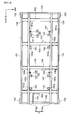
- the convey unit 10 has a conveyer frame 130 comprising a rectangular frame body 131 which has a plurality of wheels 131a, ... having locking mechanisms and is located at a predetermined height from a floor, four frame columns 132, ... standing on side surfaces near the four corners of the frame body 131, a pair of upper frame members 133, 133 which are fixed to extend between upper portions of the left-side frame columns 132, 132 and between upper portions of right-side frame columns 132, 132, respectively, and a pair of lower frame members 134, 134 which are fixed to extend between lower portions of the left-side frame columns 132, 132 and between lower portions of right-side frame columns 132, 132, respectively.
- An upper conveyer mechanism 11 is supported along the upper frame members 133, 133 and a lower conveyer mechanism 12 is supported along the lower frame members 134, 134, thereby making a two-stage structure.
- the upper frame members 133, 133 and the lower frame members 134, 134 have guide walls 133a, 134a which are disposed on the outer surfaces thereof to extend upward along the outer surfaces.
- the guide walls 133a, 134a prevent the pallets 6 on the upper conveyer mechanism 11 and the lower conveyer mechanism 12 from deviating to the left or the right.
- the upper conveyer mechanism 11 has a pair of upper belt conveyers 110a, 110b which are supported between the upper frame members 133, 133 such that the upper belt conveyers 110a, 110b are spaced apart from each other by a predetermined distance to extend in parallel to each other and horizontally by using a plurality of long supporting frame members 135, .... As shown in Fig.
- the upper belt conveyers 110a, 110b comprise long body members 111a, 111b, driving pulleys 113a, 113b and driven pulleys 114a, 114b rotatably mounted at the ends of the long body members 111a, 111b via mounting members 112, ..., and endless conveyer belts 115a, 115b which are wound around the driving pulleys 113a, 113b and the driven pulleys 114a, 114b to extend therebetween.
- the left and right driving pulleys 113a, 113b are connected to each other through a driving shaft 116. Attached to the driving shaft 116 is a first sprocket 117c.
- a driving chain 118 is wound around the first sprocket 117c and a second sprocket 117d to extend therebetween.
- the second sprocket 117d is rotated by a driving motor 119 which is fixed to the lower surface of the supporting frame member 135, whereby the first sprocket 117c is rotated through the driving chain 118 and the driving pulleys 113a, 113b are rotated in synchronism with each other via the driving shaft 116. That is, the left and right conveyer belts 115a, 115b are rotated and moved in synchronism with each other by the driving motor 119 so as to move the pallet 6 on the conveyer belts 115a, 115b rearward.
- a first holding mechanism 140 and a second holding mechanism 145 for locating and holding the pallet 6 conveyed by the upper conveyer mechanism 11 are attached to the upper conveyer mechanism 11.
- the first holding mechanism 140 comprises first sensors 141, 141 for sending a signal when the pallet 6 is located at a preset first holding position (a working position where the printer unit 20 as will be described later prints on the print substrate 5), first air cylinders 142, ...
- a first controller 143 which receives the signal, indicating that the pallet 6 is located at the first holding position, from the first sensors 141 and thus sends a control signal to the first air cylinders 142.
- the first sensors 141 each have a locating pin 141a which is expandable in the vertical direction and are disposed on the inner sides of the upper belt conveyers 110a, 110b, respectively (the total number of the first sensors 141 is two in this embodiment).
- the locating pins 141 a in the expanded state come in contact with the cutouts 6a (see Fig. 2 or Fig. 3 ), formed on the rear side of the pallet 6, when the pallet 6 conveyed on the upper belt conveyers 110a, 110b is located at the first holding position.
- the locating pins 141 a of the first sensors 141 in the contracted state do not come in contact with the pallet 6 (the cutouts 6a).
- the first sensors 141 detect pressing force produced when the cutouts 6a of the pallet 6 collide with the locating pins 141 a and thus sends a signal, indicating that the pallet 6 is located at the first holding position, to the first controller 143.
- the first controller 143 is connected to the first sensors 141 and the first air cylinders 142 via cables (not shown). Through the cables, the first controller 143 receives the signal, indicating that the pallet 6 is located at the first holding position, from the first sensors 141 and sends a control signal to the first air cylinders 142.
- the first controller 143 is mounted to the supporting frame member 135 between the upper belt conveyers 110a, 110b.
- the first air cylinders 142 each have a holding pin 142a which is expandable in the vertical direction and are disposed on the upper belt conveyers 110a, 110b two by two at positions corresponding to the position of the pallet 6 being in the first holding position (the total number of the air cylinders 142 is four in this embodiment).
- the holding pins 142a are expandable according to the control signal of the first controller 143.
- the holding pins 142a when being expanded come in contact with the lower surface of the pallet 6 and lift up the pallet 6, thereby holding the pallet 6 spaced apart from the conveyer belts 115a, 115b of the upper belt conveyers 110a, 110b.
- the pallet 6 is returned to be put on the conveyer belts 115a, 115b.
- the second holding mechanism 145 has a similar structure as the aforementioned first holding mechanism 140 and comprises second sensors 146, 146 for sending a signal when the pallet 6 is located at a preset second holding position (a position before (in front of) the first holding position in the conveying direction, that is, a standby position before the first holding position not to lap over the working position of the printer unit 20 as will be described later), second air cylinders 147, ... for lifting up the pallet 6 to space the pallet 6 apart from the upper conveyer mechanism 11 when the pallet 6 is located at the second holding position, and a second controller 148 which receives the signal, indicating that the pallet 6 is located at the second holding position, from the second sensors 146 and thus sends a control signal to the second air cylinders 147.
- a preset second holding position a position before (in front of) the first holding position in the conveying direction, that is, a standby position before the first holding position not to lap over the working position of the printer unit 20 as will be described later
- the second sensors 146 each have a locating pin 146a which is expandable in the vertical direction and are disposed on the inner sides of the upper belt conveyers 110a, 110b, respectively (the total number of the second sensors 146 is two in this embodiment).
- the locating pins 146a in the expanded state come in contact with the cutouts 6a (see Fig. 2 or Fig. 3 ), formed on the rear side of the pallet 6, when the pallet 6 conveyed on the upper belt conveyers 110a, 1 10b is located at the second holding position.
- the locating pins 146a of the second sensors 146 in the contracted state do not come in contact with the pallet 6 (the cutouts 6a).
- the second sensors 146 detect pressing force produced when the cutouts 6a of the pallet 6 collide with the locating pins 146a and thus sends a signal, indicating that the pallet 6 is located at the second holding position, to the second controller 148.
- the second controller 148 is connected to the second sensors 146 and the second air cylinders 147 via cables (not shown). Through the cables, the second controller 148 receives the signal, indicating that the pallet 6 is located at the second holding position, from the second sensors 146 and sends a control signal to the second air cylinders 147.
- the second controller 148 is mounted to the supporting frame member 135 between the upper belt conveyers 110a, 110b.
- the second air cylinders 147 each have a holding pin 147a which is expandable in the vertical direction and are disposed on the upper belt conveyers 110a, 110b two by two at positions corresponding to the position of the pallet 6 being in the second holding position (the total number of the second air cylinders 147 is four in this embodiment).
- the holding pins 147a are expandable according to the control signal of the second controller 148.
- the holding pins 147a when being expanded come in contact with the lower surface of the pallet 6 and lift up the pallet 6, thereby holding the pallet 6 spaced apart from the conveyer belts 115a, 115b of the upper belt conveyers 110a, 110b.
- the pallet 6 is returned to be put on the conveyer belts 115a, 115b.
- the lower conveyer mechanism 12 has a pair of lower belt conveyers 120a, 120b which are supported between the lower frame members 134, 134 such that the lower belt conveyers 120a, 120b are spaced apart from each other by a predetermined distance to extend in parallel to each other and horizontally by using a plurality of long supporting frame members 136, ....
- the lower belt conveyers 120a, 120b have similar structure as the upper belt conveyers 110a, 110b of the aforementioned upper conveyer mechanism 11. As shown in Fig.
- the lower belt conveyers 120a, 120b comprise long body members 121 a, 121 b, driving pulleys 123a, 123b and driven pulleys 124a, 124b rotatably mounted at the ends of the long body members 121a, 121 b via mounting members 122, ..., and endless conveyer belts 125a, 125b which are wound around the driving pulleys 123a, 123b and the driven pulleys 124a, 124b to extend therebetween.
- the left and right driving pulleys 123a, 123b are connected to each other through a driving shaft 126. Attached to the driving shaft 126 is a first sprocket 127c.
- a driving chain 128 is wound around the first sprocket 127c and a second sprocket 127d to extend therebetween.
- the second sprocket 127d is rotated by a driving motor 129 which is fixed to the lower surface of the supporting frame member 136, whereby the first sprocket 127c is rotated through the driving chain 128 and the driving pulleys 123a, 123b are rotated in synchronism with each other via the driving shaft 126. That is, the left and right conveyer belts 125a, 125b are rotated and moved in synchronism with each other by the driving motor 129 so as to move the pallet 6 on the conveyer belts 125a, 125b forward.
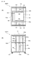
- each of the loading station unit 2a and the collecting station unit 2h has an elevation frame 152, comprising a rectangular plate-shape supporting base 152a which has a plurality of wheels 151 having locking mechanisms and is located at a predetermined height from the floor, and a wall-like frame 152b which stands on the supporting base 152a and comprises a frame section on the opposite side from the conveyer unit 10 and left and right side frame sections (having a U-like shape in a plan view), and an elevation unit 13 which is installed on the supporting base 152a.
- the elevation unit 13 comprises an elevation cylinder 153, a plurality of (four in this embodiment) guide tubes 154, ... an elevation table 155, and a pair of left and right elevation belt conveyers 160a, 160b.
- the elevation cylinder 153 and the guide tubes 154 are standing on the supporting base 152a.
- the elevation table 155 having a plate-like shape is attached to an upper end of an expandable output rod 153a of the elevation cylinder 153 and upper ends of guide rods 154a, ... which are slidably fitted to the guide tubes 154, ....
- the elevation table 155 can move up and down in the vertical direction because of the expansion and contraction of the elevation cylinder 153 (the output rod 153a).
- the pair of left and right belt conveyers 160a, 160b are disposed to extend in parallel to each other and horizontally by using a plurality of supporting frame members 156, ....
- the elevation belt conveyers 160a, 160b have the same structures as the upper belt conveyers 110a, 110b of the aforementioned upper conveyer mechanism 11 and thus comprise driving pulleys (not shown), driven pulleys (not shown), and endless conveyer belts 165a, 165b which are wound around the driving pulleys and the driven pulleys to extend therebetween.
- the left and right driving pulleys are connected to each other via a driving shaft 166 so that the conveyer belts 165a, 165b are rotated and moved in synchronism with each other via the driving chain 168 by the rotation of the driving motor (not shown) so as to move the pallet 6 on the conveyer belts 165a, 165b forward or rearward.
- the elevation belt conveyers 160a, 160b move up and down together with the elevation table 155 by the expansion and contraction of the elevation cylinder 153 (the output rod 153a) and can abut the upper belt conveyers 110a, 110b of the upper conveyer mechanism 11 or the lower belt conveyers 120a, 120a of the lower conveyer mechanism 12 composing the printing station unit 2e. As a result, the delivery of the pallet 6 is allowed between the elevation belt conveyers 160a, 160b and the upper belt conveyers 110a, 110b or the lower belt conveyers 120a, 120b.
- long guide frame members 158, 158 extending along the elevation belt conveyers 160a, 160b using a plurality of supporting frame members 157, ...
- guide walls 158a, 158a are formed to extend upward along the outer surfaces of the guide frame members 158, 158, respectively, thereby preventing the pallet 6 on the belt conveyers 160a, 160b from deviating to the left or the right.
- the printer unit 20 (the printing unit 3e) comprises anteroposterior moving mechanisms 220, 230 which are arranged on left and right sides (at the positions corresponding to the first holding mechanism 140 (the first holding position) of the aforementioned upper conveyer mechanism 11) of the of the conveyer frame 130 of the conveyer unit 10, and a printer mechanism 210 which is detachably mounted to the anteroposterior moving mechanism 220, 230.
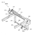
- the anteroposterior moving mechanisms 220, 230 each comprise a driving sprocket 221, 231, a first driven sprocket 222, 232, a toothed belt 223, 233 which is wound around the driving sprocket 221, 231 and the first driven sprocket 222, 232 to extend therebetween, a second driven sprocket 224, 234, and a guide roller 225, 235 so that the toothed belt 223, 233 is arranged in an L-like shape of which top is the second sprocket 224, 234.
- each driving sprocket 221, 231 and each second driven sprocket 224, 234 are rotatably supported to be spaced apart from each other in the vertical direction on the left or right side of the conveyer frame 130
- each first driven sprocket 222, 232 and each second driven sprocket 224, 234 are rotatably supported to be spaced apart from each other in the anteroposterior direction on the left or right side of each upper frame member 133, 133.
- the toothed belts 223, 233 are connected via fitting members 240, 245 at their ends, respectively so that each toothed belt 223, 233 is formed into a ring shape.
- the fitting members 240, 245 are located between the first driven sprockets 222, 232 and the second driven sprocket 224, 234, respectively.
- the left and right driving sprockets 221, 231 are connected to each other via a driving shaft 229. Attached to a middle portion of the driving shaft 229 is a driving gear 226. A train of driving gears 228a, 228b is disposed to be meshed with the driving gear 226. The train of driving gears 228a, 228b is driven to be rotated by the driving motor 227 so as to rotate the driving gear 226, thereby rotating the left and right driving sprockets 221, 231 in synchronism with each other via the driving shaft 229.
- the left and right toothed belts 223, 233 are rotated or moved in synchronism with each other by the driving motor 227 so that the left and right fitting members 240, 245 are moved in synchronism with each other in the anteroposterior direction along the upper frame members 133, 133 (the upper conveyer mechanism 11).
- the driving shaft 229, the driving motor 227, and the like are disposed below the lower frame members 134, 134 (the lower conveyer mechanism 12) so as not to interrupt the passage of the pallet 6.
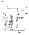
- the fitting member 240 for connecting the toothed belt 223 in the left-side anteroposterior moving mechanism 220 is shown in Fig. 10 .
- the fitting member 240 comprises a body member 241 having a U-like section and two pairs of guide rollers 242a, 242b attached to the side surface of the body member 241, in which the guide rollers 242a and 242b in each pair are aligned to be spaced apart from each other by a predetermined distance in the vertical direction and the pairs are mounted to be spaced apart from each other in the anteroposterior direction as shown in Fig. 8 .
- a guide rail 137 extending horizontally in the anteroposterior direction is attached to the outer surface of the left-side upper frame 133 of the conveyer unit 10.
- the two pairs of guide rollers 242a, 242b are fitted into the guide groves 137a, 137b which are formed in the upper and lower surfaces of the guide rail 137 so that the fitting member 240 is guided by the guide rail 137 to move in the anteroposterior direction.
- the fitting member 240 is provided with an engaging hole 241 a formed in and penetrating the upper surface of the body member 241.
- the fitting member 245 for connecting the toothed belt 233 in the right-side anteroposterior moving mechanism 230 is shown in Fig. 11 .
- the fitting member 245 comprises a body member 246 having a U-like section with a longer lower side and two pairs of guide rollers 247a, 247b attached to the side surface of the body member 246, in which the guide rollers 247a and 247b in each pair are aligned to be spaced apart from each other by a predetermined distance in the vertical direction and the pairs are mounted to be spaced apart from each other in the anteroposterior direction.
- the guide rollers 247a, 247b are arranged in a bilaterally-symmetrical pattern with the guide rollers 242a, 242b of the fitting member 240 of the left-side anteroposterior moving mechanism 220.
- a guide rail 138 extending horizontally in the anteroposterior direction is attached to the outer surface of the right-side upper frame 133 of the conveyer unit 10.
- the two pairs of guide rollers 247a, 247b are fitted into the guide groves 138a, 138b which are formed in the upper and lower surfaces of the guide rail 138 so that the fitting member 245 is guided by the guide rail 138 to move in the anteroposterior direction.
- the fitting member 245 is provided with an engaging hole 246a formed in and penetrating the upper surface of the body member 246.
- the two pairs of guide rollers 248a, 248b are fitted into the guide groves 139a, 139b which are formed in the left and right surfaces of the guide rail 139 so that the fitting member 245 is guided by the guide rail 139 to move in the anteroposterior direction. That is, the fitting member 245 can be guided by the guide rail 138 and the guide rail 139 both in the vertical direction and the lateral direction to move in the anteroposterior direction.
- the left and right toothed belt 223, 233 are rotated and moved by driving the driving motor 227 so that the left and right fitting members 240, 245 can be moved in synchronism with each other in the anteroposterior direction.
- the left side fitting member 240 is guided in the vertical direction accurately by the guide rail 137 and the right side fitting member 245 is guided in the in the vertical direction and the lateral direction accurately by the guide rails 138, 139 to move in the anteroposterior direction.
- the printer mechanism 210 is detachably attached to the left and right fitting members 240, 245 which are moved in synchronism with each other in the anteroposterior direction so that the printer mechanism 210 are entirely moved in the anteroposterior direction.
- the printer mechanism 210 comprises a long guide bar member 211 which extends in the lateral direction above the upper conveyer mechanism 11 (the upper belt conveyer 110a, 110b) and is mounted on the anteroposterior moving mechanisms 220, 230, a printer head 212 which is disposed movably along the guide bar member 211, and an ink supply device 213 and a maintenance station 214 which are mounted on the right and left ends of the guide bar member 211.
- a pair of engaging projections 211a, 211b are formed which are spaced apart from each other in the lateral direction (corresponding to a distance between the left and right fitting members 240, 245 of the anteroposterior moving mechanisms 220, 230) and project downward.
- the engaging projections 211a, 211b are fitted into the aforementioned engaging holes 241 a, 246a formed in the upper surfaces of the left and right fitting members 240, 245, whereby the guide bar member 211 is detachably mounted.
- the guide bar member 211 is also moved in the anteroposterior direction together.
- the guide bar member 211 is provided with a guide rail (not shown) extending in the lateral direction.
- a printer head 212 is disposed on the guide bar member 211 such that the printer head 212 can be guided to move in the lateral direction.
- the guide bar member 211 is also provided with a driving belt (not shown). By controlling the operation of the driving belt, the printer head 212 is controlled to move in the lateral direction along the guide bar member 211.
- the printer head 212 has a large number of inkjet nozzles (not shown) formed in its lower surface to face downward. By ejection of ink droplets from the inkjet nozzles, printing of intended characters and/or images on print substrates 5 below the inkjet nozzles is conducted.
- the ink supply device 213 is mounted on the right end of the guide bar member 211.
- the maintenance station 214 is mounted on the left end of the guide bar member 211.
- the maintenance station 214 has a device which retracts the printer head 212 into the maintenance station 214, and aspirates and cleans the remaining ink in the inkjet nozzles.
- a controller (not shown) for controlling the movement of the printer head 212 and controlling the ejection of ink droplets from the inkjet nozzles formed in the lower surface of the printer head 212.
- a cable guide 215 connecting the guide bar member 211 and the printer head 212 is provided. Wires for sending electric power and signals and flexible tubes for supplying ink are arranged within the cable guide 215. According to this structure, electric power, control signals, and ink can be supplied from the side of the guide bar member 211 (from the ink supply device 213 and the like) to the printer head 212.
- a power source and a control equipment are disposed and flexible cable guide (not shown) is disposed.
- flexible cable guide cables for sending electric power and control signals from the power source and the control equipment to control the upper and lower conveyer mechanisms 11, 12 (the driving motors 119, 129) and the first and second holding mechanism 140, 145 (the first and second controllers 143, 148) of the conveyer unit 10, the elevation cylinder 153 of the elevation unit 13, the anteroposterior moving mechanisms 220, 230 (the driving motor 227), and the printer mechanism 210 (the ink supply device 213, the controller, and the maintenance station 214) of the printer unit 20 are arranged.
- a series of actions of the printing apparatus 1' having the aforementioned structure will be described.
- print substrates 5 are put on the respective loading tables 8 of the first pallet 6 on the elevation belt conveyers 160a, 160b of the elevation unit 13 in the loading station unit 2a.
- the first pallet 6 holding the print substrates 5 thereon is moved to the upper belt conveyers 110a, 110b of the upper conveyer mechanism 11 which abut the elevation belt conveyers 160a, 160b, that is, the first pallet 6 is conveyed to the printing station unit 2e.
- the locating pins 141 a of the first sensors 141 composing the first holding mechanism 140 disposed on the upper conveyer mechanism 11 are in the expanded state and the locating pins 146a of the second sensors 146 composing the second holding mechanism 145 disposed on the upper conveyer mechanism 11 are in the contracted state.
- the first pallet 6 conveyed to the printing station unit 2e is moved backward on the upper belt conveyers 110a, 110b so that the cutouts 6a formed in the rear side of the first pallet 6 come in contact with the locating pins 141a of the first sensors 141 (the first pallet 6 is located at its working position).
- the holding pins 142a of the first air cylinders 142 are expanded according to a control signal from the first controller 143 so as to lift up the first pallet 6, thereby holding the pallet 6 spaced apart from the conveyer belts 115a, 115b of the upper belt conveyers 110a, 110b.
- the locating pins 141a of the first air cylinders 141 are contracted and the locating pins 146a of the second sensors 146 are expanded.
- the printed surfaces of the print substrates 5 on the pallet 6 and the printer head 212 (the inkjet nozzles) of the printer mechanism 210 are held in a state facing each other with a certain distance (about 2 mm) therebetween.
- ink droplets are ejected from the inkjet nozzles while the printer mechanism 210 is moved in the anteroposterior direction above the print substrates 5 on the first pallet 6 by the anteroposterior moving mechanisms 220, 230, and the printer head 212 is moved in the lateral direction along the guide bar member 211, thereby conducting printing of intended characters, images, and the like on the respective print substrates 5.
- the printer mechanism 210 In a stable state relative to the print substrates 5 without being affected by vibration of the upper belt conveyers 110a, 110b, higher precise printing can be achieved by the printer mechanism 210.
- the printer mechanism 210 By the drive control of the anteroposterior moving mechanisms 220, 230, the movement control of the printer head 212, and the ejection control of ink from the inkjet nozzles, different characters, images and the like can be printed on the respective print substrates 5 aligned in the lateral direction and held on the pallet 6, respectively.
- the holding pins 142a of the first air cylinders 142 are contracted according to the control signal of the first controller 143 so that the first pallet 6 is returned onto the conveyer belts 115a, 115b.
- the first pallet 6 returned onto the conveyer belts 115a, 115b is moved to be on the elevation belt conveyers 160a, 160b of the collecting station unit 2h which abut to the upper belt conveyers 110a, 110b so that the first pallet 6 is conveyed to the collecting station unit 2h.
- the locating pins 141 a of the first sensors 141 are expanded (the locating pins 146a of the second sensors 146 are kept in the contracted state).
- the holding pins 142a of the first air cylinders 142 are contracted according to the control signal of the first controller 143 so that the first pallet 6 is returned onto the conveyer belts 115a, 115b.
- the first pallet 6 returned onto the conveyer belts 115a, 115b is moved to be on the elevation belt conveyers 160a, 160b of the collecting station unit 2h which abut to the upper belt conveyers 110a, 110b so that the first pallet 6 is conveyed to the collecting station unit 2h.
- the locating pins 141 a of the first sensors 141 are expanded (the locating pins 146a of the second sensors 146 are kept in the contracted state).
- the respective print substrates 5 after completing the printing step on the first pallet 6 are collected by the operator.
- the first pallet 6 after the print substrates 5 are collected is moved to the lower belt conveyers 120a, 120b of the lower conveyer mechanism 12 which abut the elevation belt conveyers 160a, 160b by the operation of the elevation unit 13 (the elevation cylinder 153) so that the first pallet 6 is conveyed to the printing station unit 2e again.
- the first pallet 6 conveyed to the printing station unit 2e is conveyed on the lower belt conveyers 120a, 120b toward the loading station unit 2a.
- new print substrates 5 are put on the first pallet 6 and are then subjected to the same step as mentioned above.
- the holding pins 147a of the second air cylinders 147 are contracted according to a control signal of the second controller 148 so that the second pallet 6 is returned onto the conveyer belts 115a, 115b.
- the second pallet 6 returned onto the conveyer belts 115a, 115b are moved backward on the upper belt conveyer 110a, 110b so that the cutouts 6a formed in the rear side of the second pallet 6 come in contact with the locating pins 141 a of the first sensors 141 (the second pallet 6 is located at its working position).
- the holding pins 142a of the first air cylinders 142 are expanded according to a control signal from the first controller 143 so as to lift up the second pallet 6, thereby holding the second pallet 6 spaced apart from the conveyer belts 115a, 115b of the upper belt conveyers 110a, 110b.
- the second pallet 6 is subjected to the printing step by the printer unit 20, the conveyance to the collecting station unit 2h, the collection of the print substrates, and the conveyance to the loading station unit 2a in this order.
- the action for delivering the pallet 6 from the conveyer unit 10 (the upper conveyer mechanism 11) of the printing station unit 2e to the conveyer unit 10 (the upper conveyer mechanism 11) of the post-processing station unit 2f will be described.
- the first pallet 6 is returned onto the conveyer belts 115a, 115b by the first holding mechanism 140.
- the first pallet 6 returned onto the conveyer belts 115a, 115b is moved to the upper belt conveyers 110a, 110b of the post-processing station unit 2f which abut the upper belt conveyers 110a, 110b of the printing station unit 2e so that the first pallet 6 is conveyed to the post-processing station unit 2f.
- the locating pins 141 a of the first sensors 141 of the printing station unit 2e are in the expanded state and the locating pins 146a of the second sensors 146 are in the contracted state.
- the locating pins 141a of the first sensors 141 composing the first holding mechanisms140 disposed on the upper conveyer mechanism 11 are in the expanded state and the locating pins 146a of the second sensors 146 composing the second holding mechanism 145 disposed on the upper conveyer mechanism 11 are in the contracted state.
- the first pallet 6 conveyed to the post-processing station unit 2f is moved backward on the upper belt conveyers 110a, 110b and is held at the first holding position (the working position of the post-processing unit 3f) spaced apart from the conveyer belts 115a, 115b by the first holding mechanism 140.
- the first pallet 6 is held at the first holding position by the first holding mechanism 140, the post-processing unit 3f conducts the post-processing step by applying a protective coating material to the surfaces of the print substrates 5, on which characters, images, and the like were printed by the printer unit 20, to protect and coat the surfaces.
- the first pallet 6 is held at a position spaced apart from the conveyer belts 115a, 115b, the locating pins 141a of the first sensors 141 of the post-processing station unit 2f are in the contracted state and the locating pins 146a of the second sensors 146 of the post-processing station unit 2f are in the expanded state.
- the second holding mechanism 145 returns the second pallet 6 onto the conveyer belts 115a, 115b in the printing station unit 2e.
- the second pallet 6 returned onto the conveyer belts 115a, 115b is moved backward on the upper belt conveyers 110a, 110b and is held at the first holding position (the working position of the printer unit 20) spaced apart from the conveyer belts 115a, 115b by the fist holding mechanism 140.
- the printer unit 20 prints intended characters, images, and the like on the respective print subjects 5 held on the second pallet 6.
- the locating pins 141 a of the first sensors 141 of the printing station unit 2e are in the contracted state and the locating pins 146a of the second sensors 146 of the printing station unit 2e are in the expanded state.
- the first holding mechanism 140 returns the second pallet 6 onto the conveyer belts 115a, 115b.
- the second pallet 6 returned onto the conveyer belts 115a, 115b is moved to the upper belt conveyers 110a, 110b of the post-processing station unit 2f which abut the upper belt conveyers 110a, 110b of the printing station unit 2e.
- the second pallet 6 conveyed to the post-processing station unit 2f is moved backward on the upper belt conveyers 110a, 110b and is held at a second holding position (the standby position of the post-processing station unit 2f) spaced apart from the conveyer belts 115a, 115b of the upper belt conveyer 110a, 110b by the second holding mechanism 145.
- the second pallet 6 is held directly at the first holding position (the working position of the post-processing unit 3f) by the first holding mechanism.
- the first pallet 6 is returned onto the conveyer belts 115a, 115b by the first holding mechanism 140.
- the first pallet 6 returned onto the conveyer belts 115a, 115b is moved to the upper belt conveyers 110a, 110b of the second drying station unit 2g which abut the upper belt conveyers 110a, 110b of the post-processing station unit 2f so that the first pallet 6 is conveyed to the second drying station unit 2g.
- the first pallet 6 is subjected to the drying step by the drying unit 3g, the conveyance to the collecting station unit 2h, the collection of the print substrates, and the conveyance to the loading station unit 2a in this order.
- the second pallet 6 is returned to the conveyer belts 115a, 115b by the second holding mechanism, is moved backward on the upper belt conveyers 110a, 110b, is held at the first holding position (the working position of the post-processing unit 3f) spaced apart from the conveyer belts 115a, 115b by the first holding mechanism 140, and is then subjected to the post-processing by applying a protective coating material to the surfaces of the print substrates 5, on which characters, images, and the like were printed by the printer unit 20, to protect and coat the surfaces.
- the second pallet 6 is subjected to the conveyance to the drying station unit 2g, the drying step by the drying unit 3g, the conveyance to the collecting station unit 2h, the collection of the print substrates 5, and the conveyance to the loading station unit 2a in this order.
- first pallet 6 and the second pallet 6 a larger number of pallets 6 such as the third pallet 6, the forth pallet 6, ... can be conveyed sequentially and circulated by the respective station units 2a through 2g and subjected to respective processing operations by the work units 3b through 3f in the printing apparatus 1 according to this embodiment.
- the anteroposterior moving mechanisms 220, 230 each comprise the driving sprocket 221, 231, the first driven sprocket 222, 232, the toothed belt 223, 233 which is wound around the driving sprocket 221, 231 and the first driven sprocket 222, 232 to extend therebetween, the second driven sprocket 224, 234, and the guide roller 225, 235 which are disposed midway between the driving sprocket 221, 231 and the first driven sprocket 222, 232 so that the toothed belt 223, 233 is arranged in an L-like shape of which top is the second sprocket 224, 234.
- the toothed belts 223, 233 are connected via fitting members 240, 245 at their ends, respectively so that each toothed belt 223, 233 is formed into a ring shape.
- the fitting members 240, 245 are located between the first driven sprockets 222, 232 and the second driven sprocket 224, 234, respectively.
- the left and right driving sprockets 221, 231 are rotated via the driving shaft 229 by the driving motor 227 so that the left and right fitting members 240, 245 can be moved in synchronism with each other in the anteroposterior direction along the upper frame members 133, 133 (the upper conveyer mechanism 11).
- the toothed belts 223, 233 extend to below the lower frame members 134, 134 (the lower conveyer mechanism 12), the driving shaft 229, the driving motor 227, and the like are disposed below the lower conveyer mechanism 12, that is, the anteroposterior moving mechanisms 220, 230 can be arranged not to interrupt the passage of the pallet 6.
- the printing apparatus of the present invention is not limited to the structures of the aforementioned embodiments and printing apparatuses with various modifications and changes from the aforementioned embodiment are also included in the present invention.
Landscapes
- Engineering & Computer Science (AREA)
- Mechanical Engineering (AREA)
- Textile Engineering (AREA)
- Ink Jet (AREA)
- Dot-Matrix Printers And Others (AREA)
- Character Spaces And Line Spaces In Printers (AREA)
- Handling Of Cut Paper (AREA)
- Glass Compositions (AREA)
- Noodles (AREA)
Abstract
Description
- The present invention relates to a printing apparatus for printing intended characters, images etc. on a print substrate such as a T-shirt by sequentially conducting a plurality of processing operations.
- Conventionally, as an apparatus and method for printing characters, images, etc. on a print substrate such as a T-shirt, screen printing has been known in which a plurality of screens corresponding to printing colors are prepared and are used to print each color on the surface of the print substrate so that printed colors are overlapped. Since the screen printing requires a plurality of exclusive screens corresponding to designs and colors, making the screens is troublesome and expensive. Thus, screen printing is not suitable for high-mix low-volume production type printing. Recently, methods for printing on a print substrate such as a T-shirt by using an inkjet printer to eject ink droplets directly on the print substrate have been carried out. As known documents disclosing such a printing apparatus and method using an inkjet printer, there are Japanese Patent documents
JP-A-2002-154247 JP-A-2007-031888 - For example, for printing characters, images, etc. on a print substrate made of cloth such as a T-shirt by using an inkjet printer, it is required to conduct a lot of processing steps such as a preprocessing for the purpose of preventing ink blurring and an post-processing for the purpose of protecting images printed on the surface of the print substrate. Especially as an industrial printing apparatus, there is known an apparatus of a type that print substrates are conveyed by a conveying means such as a belt conveyer. In this case, a pallet is put on a conveying member such as conveyer belt and the print substrates are placed and held at predetermined positions on the pallet. In this state, the print substrates are conveyed together with the pallet and stopped at every working position where various working devices are placed so that print substrates are processed according to the processing steps such as the aforementioned preprocessing.
- By the way, in case that the print substrates are conveyed together with the pallet by the conveying means such as a belt conveyer and a predetermined printing process is carried out relative to the print substrates on the pallet being conveyed, it is only allowed to conduct relatively rough printing without requiring high precision and it is difficult to conduct printing requiring high precision because of variation in speed and generation of vibration during the conveyance. Therefore, there is an idea to fix the pallet at a predetermined working position on the conveying member such as a conveyer belt where a predetermined printing process is conducted relative to the print substrates. However, in such a case, there is a problem of requiring a moving mechanism for moving a working device such as a printer head having a plurality of inkjet nozzles forward, backward, leftward, and rightward above the fixed print substrates.
- The present invention is made to address the aforementioned problems and it is an object of the present invention to provide a printing apparatus in which a moving mechanism for moving a working device forward, backward, leftward, and rightward above print substrates is arranged without interrupting the passage of a pallet.
- To this end, there is provided a printing apparatus comprising:
- a pallet on which a print substrate is placed;
- a conveyer system for conveying the pallet, having an upper conveying passage and a lower conveying passage which are arranged in two stages in the vertical direction;
- a pair of left and right anteroposterior moving mechanisms which are arranged on left and right sides of the upper conveying passage and extend in the anteroposterior direction;
- a pair of left and right fitting members which are disposed on the pair of left and right anteroposterior moving mechanisms, respectively and are moved in the anteroposterior direction in synchronism with each other by the anteroposterior moving mechanisms;
- a guide bar member which extends in the lateral direction above the upper conveying passage and is mounted on the pair of left and right fitting members; and
- a head device which is disposed movably along the guide bar member and has a plurality of inkjet nozzles for ejecting ink droplets to the print substrate, wherein
- the printing apparatus is adapted to conduct printing by ejecting ink droplets from the inkjet nozzles to the print substrate on the pallet which is secured above the upper conveying passage and which is conveyed by the conveyer system while moving the head device, wherein
- a pair of left and right first driven sprockets and a pair of left and right second driven sprockets which are arranged on left and right sides of the upper conveying passage and which are rotatably disposed to be spaced apart from each other in the anteroposterior direction;
- a pair of left and right driving sprockets which are rotatably disposed below the second driven sprockets;
- a driving shaft which is disposed below the lower conveying passage and extends in the lateral direction to connect the pair of left and right driving sprockets;
- a driving device which is disposed below the lower conveying passage to rotate the driving shaft; and
- a pair of left and right endless moving members each of which is formed in a ring shape via each the fitting member and each of which is wound around each the first driven sprocket, each the second driven sprocket, and each the driving sprocket to extend around them, wherein
- the endless moving members extend in the anteroposterior direction along the upper conveying passage from the first driven sprockets to the second driven sprockets and extend downward from the second driven sprockets to the driving sprockets and wherein the fitting members are moved in the anteroposterior direction in synchronism with each other via the endless moving members by the rotation of the driving sprockets so that the head device is moved in the anteroposterior direction together with the guide bar member.
- To solve the aforementioned problem, a printing apparatus (for example, the printing apparatus 1 of the embodiment) according to the present invention comprises: a pallet (for example, the
pallet 6 in the embodiment) on which a print substrate (for example,print substrates 5 in the embodiment) is placed; a conveyer system (for example, theconveyer unit 10 in the embodiment) for conveying said pallet, having an upper conveying passage (for example, theupper conveyer mechanism 11 in the embodiment) and a lower conveying passage (for example, thelower conveyer mechanism 12 in the embodiment) which are arranged in two stages in the vertical direction; a pair of left and right anteroposterior moving mechanisms (for example, theanteroposterior moving mechanisms fitting members guide bar member 211 in the embodiment) which extends in the lateral direction above said upper conveying passage and is mounted on said pair of left and right fitting members; and a head device (for example, theprinter head 212 in the embodiment) which is disposed movably along said guide bar member and has a plurality of inkjet nozzles (for example, the inkjet nozzles in the embodiment) for ejecting ink droplets to said print substrate, wherein said printing apparatus is adapted to conduct printing by ejecting ink droplets from said inkjet nozzles to said print substrate on said pallet which is secured above said upper conveying passage and which is conveyed by said conveyer system while moving said head device, wherein said anteroposterior moving mechanisms comprise: a pair of left and right first driven sprockets (for example, the first drivensprockets sprockets sprockets driving shaft 229 in the embodiment) which is disposed below said lower conveying passage and extends in the lateral direction to connect said pair of left and right driving sprockets; a driving device (for example, thedriving gear 226, the train ofdriving gears driving motor 227 in the embodiment) which is disposed below said lower conveying passage to rotate said driving shaft; and a pair of left and right endless moving members (for example, thetoothed belts - In the printing apparatus of the present invention, the anteroposterior moving mechanisms comprise: a pair of left and right first driven sprockets and a pair of left and right second driven sprockets which are arranged on left and right sides of the upper conveying passage and which are rotatably disposed to be spaced apart from each other in the anteroposterior direction; a pair of left and right driving sprockets which are rotatably disposed below the second driven sprockets; a driving shaft which is disposed below the lower conveying passage and extends in the lateral direction to connect the pair of left and right driving sprockets; a driving device which is disposed below the lower conveying passage to rotate the driving shaft; and a pair of left and right endless moving members each of which is formed in a ring shape via each fitting member and each of which is wound around and each first driven sprocket, each second driven sprocket, and each driving sprocket to extend around them. According to this structure, the fitting members are moved in synchronism with each other via the endless moving members, which are formed in an L-like shape and arranged on left and right sides of the conveyer system, so as to move the head device in the anteroposterior direction together with the guide bar member. In addition, since the driving device and the driving shaft composing the anteroposterior moving mechanisms are arranged below the lower conveying passages, it is possible to dispose the anteroposterior moving mechanism not to interrupt the passage of the pallet.
- The above, and the other objects, features and advantages of the present invention will be made apparent from the description of the preferred embodiments, given as non-limiting examples, with reference to the accompanying drawings, in which:
-
Fig. 1 is a side view showing schematic structure of a printing apparatus according to an embodiment of the present invention; -
Fig. 2 is a perspective view showing the structures of a loading station unit, a printing station unit, and a collecting station unit as components of the printing apparatus; -
Fig. 3 is a perspective view showing the structure of a pallet on which print substrates to be printed by the printing apparatus are placed; -
Fig. 4 is a perspective view showing the structure of a conveyer unit as a component of the printing apparatus; -
Fig. 5 is a perspective view showing the structure of each of upper and lower conveyer mechanisms as parts of the conveyer unit; -
Fig. 6 is a plan view of the conveyer unit; -
Figs. 7(A), 7(B) are a plan view (A) and a side view (B) showing the structure of the loading station unit or the collecting station unit; -
Fig. 8 is a side view showing the structure of an anteroposterior moving mechanism as a part of a printer unit of the printing station unit; -
Fig. 9 is a perspective view showing a driving system of driving sprockets in the anteroposterior moving mechanism; -
Fig. 10 is a partial sectional view showing the peripheral structure of a fitting member in the left-side anteroposterior moving mechanism; and -
Fig. 11 is a partial sectional view showing the peripheral structure of a fitting member in the right-side anteroposterior moving mechanism, wherein 1...printing apparatus, 5...print substrate, 6...pallet, 10...conveyer unit, 11...upper conveyer mechanism, 12...lower conveyer mechanism, 211...guide bar member, 212...printer head, 220, 230...anteroposterior moving mechanism, 221, 231...driving sprocket, 222, 232...first driven sprocket, 223, 233...toothed belt, 224, 234... second driven sprocket, 226...driving gear, 227...driving motor, 228a, 228b...train of driving gears, 229...driving shaft, 240, 245...fitting member. -
Fig. 1 shows a schematic structure of a printing apparatus 1 according to an embodiment of the present invention. The printing apparatus 1 comprises eight work station units (aloading station unit 2a, a preprocessingstation unit 2b, a firstdrying station unit 2c, anundercoating station unit 2d, aprinting station unit 2e, anpost-processing station unit 2f, a seconddrying station unit 2g, and acollecting station unit 2h) which are aligned adjacent to each other. Thestation units 2b through 2g are provided corresponding to respective processing operations to be conducted to aprint substrate 5 such as T-shirts and each comprise a work unit (a preprocessingunit 3b, adrying unit 3c, 3g, anundercoating unit 3d, aprinting unit 3e, anpost-processing unit 3f) for conducting each processing operation. - Each of the
station units 2b through 2g has aconveyer unit 10 for conveying apallet 6 which holds theprint substrate 5 thereon. Theconveyer unit 10 comprises anupper conveyer mechanism 11 for conveying thepallet 6 holding theprint substrate 5 thereon at a working position as will be described later for each work unit (the preprocessingunit 3b, thedrying unit 3c, 3g, the undercoatingunit 3d, theprinting unit 3e, thepost-processing unit 3f), and alower conveyer mechanism 12 for conveying the empty pallet 6 (without holding the print substrate 5). Theupper conveyer mechanisms 11 and thelower conveyer mechanisms 12 are placed in a uniform way through therespective station units 2b through 2g such that ends as the pallet receiving portions and the pallet let-off portions of the respectiveupper conveyer mechanisms 11 are surely abutted to each other and also ends as the pallet receiving portions and the pallet let-off portions of the respectivelower conveyer mechanisms 12 are surely abutted to each other so as to allow the delivery of thepallet 6 between the station units. - The
loading station unit 2a and thecollecting station unit 2h each have anelevation unit pallet 6 between theupper conveyer mechanism 11 and thelower conveyer mechanism 12. Theelevation unit upper conveyer mechanism 11 and thelower conveyer mechanism 12 so as to allow the delivery of thepallet 6 between theupper conveyer mechanism 11 and thelower conveyer mechanism 12. Thepallet 6 can be conveyed and circulated through therespective station units 2a through 2h by theelevation units lower conveyer mechanisms 11, 12 (the respective conveyer units 10). - In each of the
station units 2a through 2h, eachelevation unit unit 3b, thedrying unit 3c, 3g, the undercoatingunit 3d, theprinting unit 3e, thepost-processing unit 3f) and eachconveyer unit 10 are mounted to a frame body (aconveyer frame 130, anelevation frame 152 inFig. 2 ) of each station unit and thus can be replaced or rearranged integrally with each frame body. Each frame body has wheels 14 (wheels 131 a,wheels 151 inFig. 2 ) which are fixed to the bottom thereof and have locking mechanisms, respectively, thereby easily allowing the movement of each of thestation units 2a through 2h. - In the printing apparatus 1, a
print substrate 5 is first put on thepallet 6 by an operator in theloading station unit 2a. Thepallet 6 holding theprint substrate 5 thereon is moved by theelevation unit 13 toward theupper conveyer mechanism 11 of the preprocessingstation unit 2b and is then conveyed to the next station unit i.e. thepreprocessing station unit 2b. - The preprocessing
station unit 2b comprises the preprocessingunit 3b having a preprocessing printer or the like for conducting a preprocessing step by applying base coating material (transparent ink) to the surface of the print substrate 5 (in a range where intended characters, images, etc. are printed) to previously coat the surface of theprint substrate 5. The preprocessing step is conducted for the purpose of preventing ejected inks, applied at the undercoatingstation unit 2d and theprinting station unit 2e, from penetrating inside theprint substrate 5 and preventing ink blurring. Thepallet 6 conveyed from theloading station unit 2a to the preprocessingstation unit 2b is moved to a working position, as will be described later, of the preprocessingunit 3b via a standby position, as will be described later, by theupper conveyer mechanism 11. Theprint substrate 5 on thepallet 6 is subjected to the aforementioned preprocessing step while thepallet 6 is held at the working position and is then conveyed to the next station unit i.e. the firstdrying station unit 2c. - The first
drying station unit 2c comprises the drying unit 3c having a heater or the like for drying the base coating material (transparent ink) which was applied at the preprocessingstation unit 2b (the preprocessingunit 3b) to coat the surface of theprint substrate 5. The drying step is conducted for the purpose of preventing adhesion of inks applied at the undercoatingstation unit 2d and theprinting station unit 2e from being poor and thus preventing the print quality from being poor. Thepallet 6 conveyed from the preprocessingstation unit 2b to the firstdrying station unit 2c is moved to a working position of the drying unit 3c via a standby position by theupper conveyer mechanism 11. Theprint substrate 5 on thepallet 6 is subjected to the aforementioned drying step while thepallet 6 is held at the working position and is then conveyed to the next station unit i.e. theundercoating station unit 2d. - The
undercoating station unit 2d comprises theundercoating unit 3d having an undercoat printer or the like for conducting an undercoating process by applying undercoating material (white ink) on the surface (the surface of the base coating material) of theprint substrate 5 preprocessed at thepreprocessing station unit 2b (thepreprocessing unit 3b). The undercoating process allows the intended color characters, images, etc. to be printed without affecting the color of ink ejected at theprinting station unit 2e by the color of theprint substrate 5 itself, thereby improving the chromogenic characteristics. Thepallet 6 conveyed from the firstdrying station unit 2c to theundercoating station unit 2d is moved to a working position of theundercoating unit 3d via a standby position by theupper conveyer mechanism 11. Theprint substrate 5 on thepallet 6 is subjected to the aforementioned undercoating process while thepallet 6 is held at the working position and is then conveyed to the next station unit i.e. theprinting station unit 2e. - The
printing station unit 2e comprises aprinting unit 3e having an inkjet printer or the like for conducting a printing step for printing intended characters, images, etc. by ejecting ink droplets from inkjet nozzle onto the surface of theprint substrate 5 undercoated at theundercoating station unit 2d (theundercoating unit 3d). Thepallet 6 conveyed from theundercoating station unit 2d to theprinting station unit 2e is moved to a working position of theprinting unit 3e via a standby position by theupper conveyer mechanism 11. Theprint substrate 5 on thepallet 6 is subjected to the aforementioned printing step while thepallet 6 is held at the working position and is then conveyed to the next station unit i.e. thepost-processing station unit 2f. - The
post-processing station unit 2f comprises thepost-processing unit 3f having an post-processing printer or the like for conducting an post-processing step by applying protective coating material (transparent ink) to the surface of the characters, images, etc. of theprint substrate 5 printed at theprinting station unit 2e (theprinting unit 3e) to protect and coat the surface. The post-processing step is conducted for the purpose of preventing the ejected ink of the intended characters, images, etc. printed at theprinting station unit 2e (theprinting unit 3e) from peeling off the surface of theprint substrate 5. Thepallet 6 conveyed from theprinting station unit 2e to thepost-processing station unit 2f is moved to a working position of thepost-processing unit 3f via a standby position by theupper conveyer mechanism 11. Theprint substrate 5 on thepallet 6 is subjected to the aforementioned post-processing step while thepallet 6 is held at the working position and is then conveyed to the next station unit i.e. the seconddrying station unit 2g. - The second
drying station unit 2g comprises the dryingunit 3g having a heater or the like for drying the protective coating material (transparent ink) protecting and coating the surface of the printed characters, images, etc. of theprint substrate 5 applied at thepost-processing station unit 2f (thepost-processing unit 3f). By this drying step, all of the processing operations for theprint substrate 5 are completed, thus finishing theprint substrate 5 with printed intended characters, images, etc. thereon. Thepallet 6 conveyed from thepost-processing station unit 2f to the seconddrying station unit 2g is moved to a working position of thedrying unit 3g via a standby position by theupper conveyer mechanism 11. Theprint substrate 5 on thepallet 6 is subjected to the aforementioned drying step while thepallet 6 is held at the working position and is then conveyed to the next station unit i.e. the collectingstation unit 2h. - In the collecting
station unit 2h, thefinished print substrate 5 on thepallet 6 conveyed from the seconddrying station unit 2g after the respective processing operations is collected by the operator.Empty pallet 6 after theprint substrate 5 is collected is moved by theelevation unit 13 toward thelower conveyer mechanism 12 of the seconddrying station unit 2g and is conveyed to theloading station unit 2a through thepost-processing station unit 2f, theprinting station unit 2e, theundercoating station unit 2d, the firstdrying station unit 2c, and thepreprocessing station unit 2b in this order by thelower conveyer mechanisms 12. Then, at theloading station unit 2a, anew print substrate 5 is put on theempty pallet 6 and is subjected to the aforementioned steps. - Then, the structure of the conveyer unit 10 (the
upper conveyer mechanism 11 and the lower conveyer mechanism 12) of each of thestation unit 2b through 2g and the structure of theelevation unit 13 of each of theloading station unit 2a and the collectingstation unit 2h will be described in detail with regard toFig. 2 through Fig. 7 .Fig. 2 shows a printing apparatus 1' comprising aloading station unit 2a, aprinting station unit 2e, and a collectingstation unit 2h which are aligned adjacent to each other. For the sake of convenience, inFig. 2 through Fig. 6 , directions indicated by arrows "UP", "FRONT", AND "LEFT" will be upward, forward, and leftward directions in the following description. - The
printing station unit 2e comprises aconveyer unit 10 which is composed of anupper conveyer mechanism 11 for conveying apallet 6 holding aprint substrate 5 thereon, alower conveyer mechanism 12, and a printer unit 20 (aprinting unit 3e) as will be described later. As show inFig. 3 , thepallet 6 is formed into a rectangular plate-shape and has a pair of longtable supporting members table supporting members top panel 8a having a rectangular plate shape for holding eachprint substrate 5 thereon and fourleg members 8b extending downwardly from the lower surface of thetop panel 8a. Thepallet 6 is provided with fourcutouts 6a two of which are formed in each of the front and rear side surfaces thereof and which can come in contact with to locatingpins 141a offirst sensors 141 and locatingpins 146a ofsecond sensors 146. - As shown in
Fig. 4 , the conveyunit 10 has aconveyer frame 130 comprising arectangular frame body 131 which has a plurality ofwheels 131a, ... having locking mechanisms and is located at a predetermined height from a floor, fourframe columns 132, ... standing on side surfaces near the four corners of theframe body 131, a pair ofupper frame members side frame columns side frame columns lower frame members side frame columns side frame columns upper conveyer mechanism 11 is supported along theupper frame members lower conveyer mechanism 12 is supported along thelower frame members upper frame members lower frame members guide walls guide walls pallets 6 on theupper conveyer mechanism 11 and thelower conveyer mechanism 12 from deviating to the left or the right. - The
upper conveyer mechanism 11 has a pair ofupper belt conveyers upper frame members upper belt conveyers frame members 135, .... As shown inFig. 5 , theupper belt conveyers long body members pulleys pulleys 114a, 114b rotatably mounted at the ends of thelong body members members 112, ..., andendless conveyer belts pulleys pulleys shaft 116. Attached to the drivingshaft 116 is afirst sprocket 117c. A drivingchain 118 is wound around thefirst sprocket 117c and asecond sprocket 117d to extend therebetween. Thesecond sprocket 117d is rotated by a drivingmotor 119 which is fixed to the lower surface of the supportingframe member 135, whereby thefirst sprocket 117c is rotated through the drivingchain 118 and the drivingpulleys shaft 116. That is, the left andright conveyer belts motor 119 so as to move thepallet 6 on theconveyer belts - At predetermined positions in the feeding direction (the anteroposterior direction) of the
upper conveyer mechanism 11, as shown inFig. 6 , afirst holding mechanism 140 and asecond holding mechanism 145 for locating and holding thepallet 6 conveyed by theupper conveyer mechanism 11 are attached to theupper conveyer mechanism 11. Thefirst holding mechanism 140 comprisesfirst sensors pallet 6 is located at a preset first holding position (a working position where theprinter unit 20 as will be described later prints on the print substrate 5),first air cylinders 142, ... for lifting up thepallet 6 to space thepallet 6 apart from the upper conveyer mechanism 11 (theconveyer belts pallet 6 is located at the first holding position, and afirst controller 143 which receives the signal, indicating that thepallet 6 is located at the first holding position, from thefirst sensors 141 and thus sends a control signal to thefirst air cylinders 142. - The
first sensors 141 each have alocating pin 141a which is expandable in the vertical direction and are disposed on the inner sides of theupper belt conveyers first sensors 141 is two in this embodiment). The locating pins 141 a in the expanded state come in contact with thecutouts 6a (seeFig. 2 orFig. 3 ), formed on the rear side of thepallet 6, when thepallet 6 conveyed on theupper belt conveyers first sensors 141 in the contracted state do not come in contact with the pallet 6 (thecutouts 6a). Thefirst sensors 141 detect pressing force produced when thecutouts 6a of thepallet 6 collide with the locating pins 141 a and thus sends a signal, indicating that thepallet 6 is located at the first holding position, to thefirst controller 143. - The
first controller 143 is connected to thefirst sensors 141 and thefirst air cylinders 142 via cables (not shown). Through the cables, thefirst controller 143 receives the signal, indicating that thepallet 6 is located at the first holding position, from thefirst sensors 141 and sends a control signal to thefirst air cylinders 142. Thefirst controller 143 is mounted to the supportingframe member 135 between theupper belt conveyers - The
first air cylinders 142 each have aholding pin 142a which is expandable in the vertical direction and are disposed on theupper belt conveyers pallet 6 being in the first holding position (the total number of theair cylinders 142 is four in this embodiment). The holdingpins 142a are expandable according to the control signal of thefirst controller 143. The holdingpins 142a when being expanded come in contact with the lower surface of thepallet 6 and lift up thepallet 6, thereby holding thepallet 6 spaced apart from theconveyer belts upper belt conveyers first air cylinders 142 are contracted according to the control signal of thefirst controller 143 from the state holding thepallet 6 spaced apart from theconveyer belts pallet 6 is returned to be put on theconveyer belts - The
second holding mechanism 145 has a similar structure as the aforementionedfirst holding mechanism 140 and comprisessecond sensors pallet 6 is located at a preset second holding position (a position before (in front of) the first holding position in the conveying direction, that is, a standby position before the first holding position not to lap over the working position of theprinter unit 20 as will be described later),second air cylinders 147, ... for lifting up thepallet 6 to space thepallet 6 apart from theupper conveyer mechanism 11 when thepallet 6 is located at the second holding position, and asecond controller 148 which receives the signal, indicating that thepallet 6 is located at the second holding position, from thesecond sensors 146 and thus sends a control signal to thesecond air cylinders 147. - The
second sensors 146 each have alocating pin 146a which is expandable in the vertical direction and are disposed on the inner sides of theupper belt conveyers second sensors 146 is two in this embodiment). The locatingpins 146a in the expanded state come in contact with thecutouts 6a (seeFig. 2 orFig. 3 ), formed on the rear side of thepallet 6, when thepallet 6 conveyed on theupper belt conveyers 110a, 1 10b is located at the second holding position. It should be noted that the locating pins 146a of thesecond sensors 146 in the contracted state do not come in contact with the pallet 6 (thecutouts 6a). Thesecond sensors 146 detect pressing force produced when thecutouts 6a of thepallet 6 collide with the locatingpins 146a and thus sends a signal, indicating that thepallet 6 is located at the second holding position, to thesecond controller 148. - The
second controller 148 is connected to thesecond sensors 146 and thesecond air cylinders 147 via cables (not shown). Through the cables, thesecond controller 148 receives the signal, indicating that thepallet 6 is located at the second holding position, from thesecond sensors 146 and sends a control signal to thesecond air cylinders 147. Thesecond controller 148 is mounted to the supportingframe member 135 between theupper belt conveyers - The
second air cylinders 147 each have aholding pin 147a which is expandable in the vertical direction and are disposed on theupper belt conveyers pallet 6 being in the second holding position (the total number of thesecond air cylinders 147 is four in this embodiment). The holdingpins 147a are expandable according to the control signal of thesecond controller 148. The holdingpins 147a when being expanded come in contact with the lower surface of thepallet 6 and lift up thepallet 6, thereby holding thepallet 6 spaced apart from theconveyer belts upper belt conveyers second air cylinders 147 are contracted according to the control signal of thesecond controller 148 from the state holding thepallet 6 spaced apart from theconveyer belts pallet 6 is returned to be put on theconveyer belts - As shown in
Fig. 4 , thelower conveyer mechanism 12 has a pair oflower belt conveyers lower frame members lower belt conveyers frame members 136, .... Thelower belt conveyers upper belt conveyers upper conveyer mechanism 11. As shown inFig. 5 , thelower belt conveyers long body members pulleys pulleys long body members members 122, ..., andendless conveyer belts pulleys pulleys shaft 126. Attached to the drivingshaft 126 is afirst sprocket 127c. A drivingchain 128 is wound around thefirst sprocket 127c and asecond sprocket 127d to extend therebetween. Thesecond sprocket 127d is rotated by a drivingmotor 129 which is fixed to the lower surface of the supportingframe member 136, whereby thefirst sprocket 127c is rotated through the drivingchain 128 and the drivingpulleys shaft 126. That is, the left andright conveyer belts motor 129 so as to move thepallet 6 on theconveyer belts - The
loading station unit 2a and the collectingstation unit 2h have the same structures. As shown inFig. 7 , each of theloading station unit 2a and the collectingstation unit 2h has anelevation frame 152, comprising a rectangular plate-shape supporting base 152a which has a plurality ofwheels 151 having locking mechanisms and is located at a predetermined height from the floor, and a wall-like frame 152b which stands on the supportingbase 152a and comprises a frame section on the opposite side from theconveyer unit 10 and left and right side frame sections (having a U-like shape in a plan view), and anelevation unit 13 which is installed on the supportingbase 152a. - The
elevation unit 13 comprises anelevation cylinder 153, a plurality of (four in this embodiment)guide tubes 154, ... an elevation table 155, and a pair of left and rightelevation belt conveyers elevation cylinder 153 and theguide tubes 154 are standing on the supportingbase 152a. The elevation table 155 having a plate-like shape is attached to an upper end of anexpandable output rod 153a of theelevation cylinder 153 and upper ends ofguide rods 154a, ... which are slidably fitted to theguide tubes 154, .... The elevation table 155 can move up and down in the vertical direction because of the expansion and contraction of the elevation cylinder 153 (theoutput rod 153a). - On the left and right sides of the elevation table 155, the pair of left and
right belt conveyers frame members 156, .... Theelevation belt conveyers upper belt conveyers upper conveyer mechanism 11 and thus comprise driving pulleys (not shown), driven pulleys (not shown), andendless conveyer belts shaft 166 so that theconveyer belts chain 168 by the rotation of the driving motor (not shown) so as to move thepallet 6 on theconveyer belts - The
elevation belt conveyers output rod 153a) and can abut theupper belt conveyers upper conveyer mechanism 11 or thelower belt conveyers lower conveyer mechanism 12 composing theprinting station unit 2e. As a result, the delivery of thepallet 6 is allowed between theelevation belt conveyers upper belt conveyers lower belt conveyers elevation belt conveyers guide frame members elevation belt conveyers frame members 157, ... are arranged. On the outer surfaces of theguide frame members guide walls guide frame members pallet 6 on thebelt conveyers - Hereinafter, the detailed structure of the
printer unit 20 of theprinting station unit 2e will be described with regard toFig. 2 , andFig. 8 throughFig. 11 . As shown inFig. 2 , the printer unit 20 (theprinting unit 3e) comprises anteroposterior movingmechanisms conveyer frame 130 of theconveyer unit 10, and aprinter mechanism 210 which is detachably mounted to theanteroposterior moving mechanism - As shown
Fig. 8 , the anteroposterior movingmechanisms sprocket sprocket toothed belt sprocket sprocket sprocket guide roller toothed belt second sprocket sprocket sprocket 224, 234 (eachguide roller 225, 235) are rotatably supported to be spaced apart from each other in the vertical direction on the left or right side of theconveyer frame 130, and each first drivensprocket sprocket 224, 234 (eachguide roller 225, 235) are rotatably supported to be spaced apart from each other in the anteroposterior direction on the left or right side of eachupper frame member toothed belts members toothed belt fitting members sprockets sprocket - As shown in
Fig. 9 , the left and right drivingsprockets shaft 229. Attached to a middle portion of the drivingshaft 229 is adriving gear 226. A train of drivinggears driving gear 226. The train of drivinggears motor 227 so as to rotate thedriving gear 226, thereby rotating the left and right drivingsprockets shaft 229. That is, the left and righttoothed belts motor 227 so that the left and rightfitting members upper frame members 133, 133 (the upper conveyer mechanism 11). The drivingshaft 229, the drivingmotor 227, and the like are disposed below thelower frame members 134, 134 (the lower conveyer mechanism 12) so as not to interrupt the passage of thepallet 6. - The
fitting member 240 for connecting thetoothed belt 223 in the left-side anteroposterior movingmechanism 220 is shown inFig. 10 . Thefitting member 240 comprises abody member 241 having a U-like section and two pairs ofguide rollers body member 241, in which theguide rollers Fig. 8 . On the other hand, aguide rail 137 extending horizontally in the anteroposterior direction is attached to the outer surface of the left-sideupper frame 133 of theconveyer unit 10. The two pairs ofguide rollers guide groves guide rail 137 so that thefitting member 240 is guided by theguide rail 137 to move in the anteroposterior direction. Thefitting member 240 is provided with anengaging hole 241 a formed in and penetrating the upper surface of thebody member 241. - The
fitting member 245 for connecting thetoothed belt 233 in the right-side anteroposterior movingmechanism 230 is shown inFig. 11 . Thefitting member 245 comprises abody member 246 having a U-like section with a longer lower side and two pairs ofguide rollers body member 246, in which theguide rollers guide rollers guide rollers fitting member 240 of the left-side anteroposterior movingmechanism 220. On the other hand, aguide rail 138 extending horizontally in the anteroposterior direction is attached to the outer surface of the right-sideupper frame 133 of theconveyer unit 10. The two pairs ofguide rollers guide groves guide rail 138 so that thefitting member 245 is guided by theguide rail 138 to move in the anteroposterior direction. Thefitting member 245 is provided with an engaginghole 246a formed in and penetrating the upper surface of thebody member 246. - Two pairs of
guide rollers body member 246, in which theguide rollers upper frame 133 of theconveyer unit 10, aguide surface 133b facing upward and extending in the anteroposterior direction is formed and aguide rail 139 extending in the anteroposterior direction is attached to theguide surface 133b. The two pairs ofguide rollers guide groves guide rail 139 so that thefitting member 245 is guided by theguide rail 139 to move in the anteroposterior direction. That is, thefitting member 245 can be guided by theguide rail 138 and theguide rail 139 both in the vertical direction and the lateral direction to move in the anteroposterior direction. - As apparent from the description of the structure, the left and right
toothed belt motor 227 so that the left and rightfitting members side fitting member 240 is guided in the vertical direction accurately by theguide rail 137 and the rightside fitting member 245 is guided in the in the vertical direction and the lateral direction accurately by theguide rails printer mechanism 210 is detachably attached to the left and rightfitting members printer mechanism 210 are entirely moved in the anteroposterior direction. - As shown in
Fig. 2 , theprinter mechanism 210 comprises a longguide bar member 211 which extends in the lateral direction above the upper conveyer mechanism 11 (theupper belt conveyer mechanisms printer head 212 which is disposed movably along theguide bar member 211, and anink supply device 213 and amaintenance station 214 which are mounted on the right and left ends of theguide bar member 211. - On the lower surface of the
guide bar member 211, a pair of engagingprojections Figs. 10, 11 ) are formed which are spaced apart from each other in the lateral direction (corresponding to a distance between the left and rightfitting members mechanisms 220, 230) and project downward. The engagingprojections holes fitting members guide bar member 211 is detachably mounted. As a result, as the left and rightfitting members guide bar member 211 is also moved in the anteroposterior direction together. - The
guide bar member 211 is provided with a guide rail (not shown) extending in the lateral direction. Aprinter head 212 is disposed on theguide bar member 211 such that theprinter head 212 can be guided to move in the lateral direction. Theguide bar member 211 is also provided with a driving belt (not shown). By controlling the operation of the driving belt, theprinter head 212 is controlled to move in the lateral direction along theguide bar member 211. Theprinter head 212 has a large number of inkjet nozzles (not shown) formed in its lower surface to face downward. By ejection of ink droplets from the inkjet nozzles, printing of intended characters and/or images onprint substrates 5 below the inkjet nozzles is conducted. - The
ink supply device 213 is mounted on the right end of theguide bar member 211. Themaintenance station 214 is mounted on the left end of theguide bar member 211. Themaintenance station 214 has a device which retracts theprinter head 212 into themaintenance station 214, and aspirates and cleans the remaining ink in the inkjet nozzles. In addition to theink supply device 213, disposed on the right end portion of theguide bar member 211 is a controller (not shown) for controlling the movement of theprinter head 212 and controlling the ejection of ink droplets from the inkjet nozzles formed in the lower surface of theprinter head 212. - A
cable guide 215 connecting theguide bar member 211 and theprinter head 212 is provided. Wires for sending electric power and signals and flexible tubes for supplying ink are arranged within thecable guide 215. According to this structure, electric power, control signals, and ink can be supplied from the side of the guide bar member 211 (from theink supply device 213 and the like) to theprinter head 212. - Below the
conveyer unit 10, a power source and a control equipment (not shown) are disposed and flexible cable guide (not shown) is disposed. In the flexible cable guide, cables for sending electric power and control signals from the power source and the control equipment to control the upper andlower conveyer mechanisms 11, 12 (the drivingmotors 119, 129) and the first andsecond holding mechanism 140, 145 (the first andsecond controllers 143, 148) of theconveyer unit 10, theelevation cylinder 153 of theelevation unit 13, the anteroposterior movingmechanisms 220, 230 (the driving motor 227), and the printer mechanism 210 (theink supply device 213, the controller, and the maintenance station 214) of theprinter unit 20 are arranged. - A series of actions of the printing apparatus 1' having the aforementioned structure will be described. First, by an operator,
print substrates 5 are put on the respective loading tables 8 of thefirst pallet 6 on theelevation belt conveyers elevation unit 13 in theloading station unit 2a. Thefirst pallet 6 holding theprint substrates 5 thereon is moved to theupper belt conveyers upper conveyer mechanism 11 which abut theelevation belt conveyers first pallet 6 is conveyed to theprinting station unit 2e. - In the
printing station unit 2e, first the locating pins 141 a of thefirst sensors 141 composing thefirst holding mechanism 140 disposed on theupper conveyer mechanism 11 are in the expanded state and the locating pins 146a of thesecond sensors 146 composing thesecond holding mechanism 145 disposed on theupper conveyer mechanism 11 are in the contracted state. Thefirst pallet 6 conveyed to theprinting station unit 2e is moved backward on theupper belt conveyers cutouts 6a formed in the rear side of thefirst pallet 6 come in contact with the locating pins 141a of the first sensors 141 (thefirst pallet 6 is located at its working position). As thecutouts 6a of thefirst pallet 6 come in contact with the locating pins 141 a, the holding pins 142a of thefirst air cylinders 142 are expanded according to a control signal from thefirst controller 143 so as to lift up thefirst pallet 6, thereby holding thepallet 6 spaced apart from theconveyer belts upper belt conveyers first pallet 6 is held in the state spaced apart from theconveyer belts first air cylinders 141 are contracted and the locating pins 146a of thesecond sensors 146 are expanded. - As the
first pallet 6 is held at the first holding position (the working position) by thefirst holding mechanism 140, the printed surfaces of theprint substrates 5 on thepallet 6 and the printer head 212 (the inkjet nozzles) of theprinter mechanism 210 are held in a state facing each other with a certain distance (about 2 mm) therebetween. In this state, ink droplets are ejected from the inkjet nozzles while theprinter mechanism 210 is moved in the anteroposterior direction above theprint substrates 5 on thefirst pallet 6 by the anteroposterior movingmechanisms printer head 212 is moved in the lateral direction along theguide bar member 211, thereby conducting printing of intended characters, images, and the like on therespective print substrates 5. In a stable state relative to theprint substrates 5 without being affected by vibration of theupper belt conveyers printer mechanism 210. By the drive control of the anteroposterior movingmechanisms printer head 212, and the ejection control of ink from the inkjet nozzles, different characters, images and the like can be printed on therespective print substrates 5 aligned in the lateral direction and held on thepallet 6, respectively. - On the other hand, when printing step is conducted by the
printer unit 20 in a state that thefirst pallet 6 is held at the first holding position,new print substrates 5 are put on the respective loading tables 8 of thesecond pallet 6 on theelevation belt conveyers elevation unit 13 by the operator in theloading station unit 2a. Thesecond pallet 6 holding theprint substrates 5 thereon is moved to theupper belt conveyers upper conveyer mechanism 11 which about theelevation belt conveyers second pallet 6 is conveyed to theprinting station unit 2e. - As the
second pallet 6 is held at the second holding position (the standby position) by thesecond holding mechanism 145 and then the printing step by theprinter unit 20 relative to thefirst pallet 6 held at the first holding position is completed, the holding pins 142a of thefirst air cylinders 142 are contracted according to the control signal of thefirst controller 143 so that thefirst pallet 6 is returned onto theconveyer belts first pallet 6 returned onto theconveyer belts elevation belt conveyers station unit 2h which abut to theupper belt conveyers first pallet 6 is conveyed to the collectingstation unit 2h. As thefirst pallet 6 is conveyed to the collectingstation unit 2h, the locating pins 141 a of thefirst sensors 141 are expanded (the locating pins 146a of thesecond sensors 146 are kept in the contracted state). - As the
second pallet 6 is held at the second holding position (the standby position) by thesecond holding mechanism 145 and then the printing step by theprinter unit 20 relative to thefirst pallet 6 held at the first holding position is completed, the holding pins 142a of thefirst air cylinders 142 are contracted according to the control signal of thefirst controller 143 so that thefirst pallet 6 is returned onto theconveyer belts first pallet 6 returned onto theconveyer belts elevation belt conveyers station unit 2h which abut to theupper belt conveyers first pallet 6 is conveyed to the collectingstation unit 2h. As thefirst pallet 6 is conveyed to the collectingstation unit 2h, the locating pins 141 a of thefirst sensors 141 are expanded (the locating pins 146a of thesecond sensors 146 are kept in the contracted state). - As the
first pallet 6 is conveyed to the collectingstation unit 2h, therespective print substrates 5 after completing the printing step on thefirst pallet 6 are collected by the operator. Thefirst pallet 6 after theprint substrates 5 are collected is moved to thelower belt conveyers lower conveyer mechanism 12 which abut theelevation belt conveyers first pallet 6 is conveyed to theprinting station unit 2e again. Thefirst pallet 6 conveyed to theprinting station unit 2e is conveyed on thelower belt conveyers loading station unit 2a. In theloading station unit 2a,new print substrates 5 are put on thefirst pallet 6 and are then subjected to the same step as mentioned above. - On the other hand, as the
first pallet 6 is conveyed to the collectingstation unit 2h, the holding pins 147a of thesecond air cylinders 147 are contracted according to a control signal of thesecond controller 148 so that thesecond pallet 6 is returned onto theconveyer belts second pallet 6 returned onto theconveyer belts upper belt conveyer cutouts 6a formed in the rear side of thesecond pallet 6 come in contact with the locating pins 141 a of the first sensors 141 (thesecond pallet 6 is located at its working position). As thecutouts 6a of thesecond pallet 6 come in contact with the locating pins 141 a, the holding pins 142a of thefirst air cylinders 142 are expanded according to a control signal from thefirst controller 143 so as to lift up thesecond pallet 6, thereby holding thesecond pallet 6 spaced apart from theconveyer belts upper belt conveyers first pallet 6, thesecond pallet 6 is subjected to the printing step by theprinter unit 20, the conveyance to the collectingstation unit 2h, the collection of the print substrates, and the conveyance to theloading station unit 2a in this order. Even when processing operations are conducted concurrently by a plurality of working devices like the aforementioned case, it is not necessary to keep the next pallet waiting until all of the processing operations are terminated because it is possible to make thesecond pallet 6 wait by thesecond holding mechanism 145, thereby preventing reduction in the operation rates of the working devices. - As mentioned above, though the detailed structure and the actions of the
conveyer unit 10 and theelevation unit 13 have been described with regard to the printing apparatus 1' in which theloading station unit 2a, theprinting station unit 2e, and the collectingstation unit 2h are aligned to abut each other as shown inFig. 2 , work station units such as thepreprocessing station unit 2b, the firstdrying station unit 2c, ... are further aligned to abut in addition to the above three work station units in the printing apparatus of this embodiment as shown inFig. 1 . Therefore, in the printing apparatus 1, besides the actions mentioned above, an action for delivering the pallet from aconveyer unit 10 to aconveyer unit 10 of another work station unit is generated. - Hereinafter, for example, the action for delivering the
pallet 6 from the conveyer unit 10 (the upper conveyer mechanism 11) of theprinting station unit 2e to the conveyer unit 10 (the upper conveyer mechanism 11) of thepost-processing station unit 2f will be described. In theprinting station unit 2e, as the printing step relative to thefirst pallet 6 held at the first holding position is completed by theprinter unit 20 as mentioned above, thefirst pallet 6 is returned onto theconveyer belts first holding mechanism 140. Thefirst pallet 6 returned onto theconveyer belts upper belt conveyers post-processing station unit 2f which abut theupper belt conveyers printing station unit 2e so that thefirst pallet 6 is conveyed to thepost-processing station unit 2f. As thefirst pallet 6 is conveyed to thepost-processing station unit 2f, the locating pins 141 a of thefirst sensors 141 of theprinting station unit 2e are in the expanded state and the locating pins 146a of thesecond sensors 146 are in the contracted state. - In the
post-processing station unit 2f, first the locating pins 141a of thefirst sensors 141 composing the first holding mechanisms140 disposed on theupper conveyer mechanism 11 are in the expanded state and the locating pins 146a of thesecond sensors 146 composing thesecond holding mechanism 145 disposed on theupper conveyer mechanism 11 are in the contracted state. Thefirst pallet 6 conveyed to thepost-processing station unit 2f is moved backward on theupper belt conveyers post-processing unit 3f) spaced apart from theconveyer belts first holding mechanism 140. Thefirst pallet 6 is held at the first holding position by thefirst holding mechanism 140, thepost-processing unit 3f conducts the post-processing step by applying a protective coating material to the surfaces of theprint substrates 5, on which characters, images, and the like were printed by theprinter unit 20, to protect and coat the surfaces. As thefirst pallet 6 is held at a position spaced apart from theconveyer belts first sensors 141 of thepost-processing station unit 2f are in the contracted state and the locating pins 146a of thesecond sensors 146 of thepost-processing station unit 2f are in the expanded state. - On the other hand, as the
first pallet 6 is conveyed to thepost-processing station unit 2f, thesecond holding mechanism 145 returns thesecond pallet 6 onto theconveyer belts printing station unit 2e. Thesecond pallet 6 returned onto theconveyer belts upper belt conveyers conveyer belts fist holding mechanism 140. As thesecond pallet 6 is held at the first holding position by thefirst holding mechanism 140, theprinter unit 20 prints intended characters, images, and the like on therespective print subjects 5 held on thesecond pallet 6. As thesecond pallet 6 is held at a position spaced apart from theconveyer belts first sensors 141 of theprinting station unit 2e are in the contracted state and the locating pins 146a of thesecond sensors 146 of theprinting station unit 2e are in the expanded state. - As the printing step by the
printer unit 20 relative to thesecond pallet 6 held at the first holding position is terminated, thefirst holding mechanism 140 returns thesecond pallet 6 onto theconveyer belts second pallet 6 returned onto theconveyer belts upper belt conveyers post-processing station unit 2f which abut theupper belt conveyers printing station unit 2e. Thesecond pallet 6 conveyed to thepost-processing station unit 2f is moved backward on theupper belt conveyers post-processing station unit 2f) spaced apart from theconveyer belts upper belt conveyer second holding mechanism 145. In case that thefirst pallet 6 after the post-processing is already conveyed to the following seconddrying station unit 2g when thesecond pallet 6 is conveyed to thepost-processing station unit 2f, thesecond pallet 6 is held directly at the first holding position (the working position of thepost-processing unit 3f) by the first holding mechanism. - After the post-processing by the
post-processing unit 3f relative to thefirst pallet 6 held at the first holding position is terminated in thepost-processing station unit 2f, thefirst pallet 6 is returned onto theconveyer belts first holding mechanism 140. Thefirst pallet 6 returned onto theconveyer belts upper belt conveyers drying station unit 2g which abut theupper belt conveyers post-processing station unit 2f so that thefirst pallet 6 is conveyed to the seconddrying station unit 2g. After that, similarly to the above, thefirst pallet 6 is subjected to the drying step by the dryingunit 3g, the conveyance to the collectingstation unit 2h, the collection of the print substrates, and the conveyance to theloading station unit 2a in this order. - In the
post-processing station unit 2f, thesecond pallet 6 is returned to theconveyer belts upper belt conveyers post-processing unit 3f) spaced apart from theconveyer belts first holding mechanism 140, and is then subjected to the post-processing by applying a protective coating material to the surfaces of theprint substrates 5, on which characters, images, and the like were printed by theprinter unit 20, to protect and coat the surfaces. After that, similarly to the aforementionedfirst pallet 6, thesecond pallet 6 is subjected to the conveyance to the dryingstation unit 2g, the drying step by the dryingunit 3g, the conveyance to the collectingstation unit 2h, the collection of theprint substrates 5, and the conveyance to theloading station unit 2a in this order. - Though the above description has been made with regard to the
first pallet 6 and thesecond pallet 6, a larger number ofpallets 6 such as thethird pallet 6, theforth pallet 6, ... can be conveyed sequentially and circulated by therespective station units 2a through 2g and subjected to respective processing operations by thework units 3b through 3f in the printing apparatus 1 according to this embodiment. - As mentioned in the above, in the printing apparatus 1, the anteroposterior moving
mechanisms sprocket sprocket toothed belt sprocket sprocket sprocket guide roller sprocket sprocket toothed belt second sprocket toothed belts members toothed belt fitting members sprockets sprocket sprockets shaft 229 by the drivingmotor 227 so that the left and rightfitting members upper frame members 133, 133 (the upper conveyer mechanism 11). Further, since thetoothed belts lower frame members 134, 134 (the lower conveyer mechanism 12), the drivingshaft 229, the drivingmotor 227, and the like are disposed below thelower conveyer mechanism 12, that is, the anteroposterior movingmechanisms pallet 6. - Though the present invention has been described with regard to the preferred embodiments, the printing apparatus of the present invention is not limited to the structures of the aforementioned embodiments and printing apparatuses with various modifications and changes from the aforementioned embodiment are also included in the present invention.
Claims (1)
- A printing apparatus comprising:a pallet on which a print substrate is placed;a conveyer system for conveying said pallet, having an upper conveying passage and a lower conveying passage which are arranged in two stages in the vertical direction;a pair of left and right anteroposterior moving mechanisms which are arranged on left and right sides of the upper conveying passage and extend in the anteroposterior direction;a pair of left and right fitting members which are disposed on the pair of left and right anteroposterior moving mechanisms, respectively and are moved in the anteroposterior direction in synchronism with each other by said anteroposterior moving mechanisms;a guide bar member which extends in the lateral direction above said upper conveying passage and is mounted on said pair of left and right fitting members; anda head device which is disposed movably along said guide bar member and has a plurality of inkjet nozzles for ejecting ink droplets to said print substrate, whereinsaid printing apparatus is adapted to conduct printing by ejecting ink droplets from said inkjet nozzles to said print substrate on said pallet which is secured above said upper conveying passage and which is conveyed by said conveyer system while moving said head device, whereinsaid anteroposterior moving mechanisms comprise:a pair of left and right first driven sprockets and a pair of left and right second driven sprockets which are arranged on left and right sides of said upper conveying passage and which are rotatably disposed to be spaced apart from each other in the anteroposterior direction;a pair of left and right driving sprockets which are rotatably disposed below said second driven sprockets;a driving shaft which is disposed below said lower conveying passage and extends in the lateral direction to connect said pair of left and right driving sprockets;a driving device which is disposed below said lower conveying passage to rotate said driving shaft; anda pair of left and right endless moving members each of which is formed in a ring shape via each said fitting member and each of which is wound around each said first driven sprocket, each said second driven sprocket, and each said driving sprocket to extend around them, whereinsaid endless moving members extend in the anteroposterior direction along said upper conveying passage from said first driven sprockets to said second driven sprockets and extend downward from said second driven sprockets to said driving sprockets and wherein said fitting members are moved in the anteroposterior direction in synchronism with each other via said endless moving members by the rotation of said driving sprockets so that said head device is moved in the anteroposterior direction together with said guide bar member.
Applications Claiming Priority (1)
| Application Number | Priority Date | Filing Date | Title |
|---|---|---|---|
| JP2007224791A JP4995670B2 (en) | 2007-08-30 | 2007-08-30 | Printing device |
Publications (2)
| Publication Number | Publication Date |
|---|---|
| EP2033795A1 true EP2033795A1 (en) | 2009-03-11 |
| EP2033795B1 EP2033795B1 (en) | 2009-10-21 |
Family
ID=39718978
Family Applications (1)
| Application Number | Title | Priority Date | Filing Date |
|---|---|---|---|
| EP08290642A Not-in-force EP2033795B1 (en) | 2007-08-30 | 2008-07-01 | Printing apparatus |
Country Status (7)
| Country | Link |
|---|---|
| US (1) | US8047646B2 (en) |
| EP (1) | EP2033795B1 (en) |
| JP (1) | JP4995670B2 (en) |
| KR (1) | KR100907726B1 (en) |
| CN (1) | CN101376299B (en) |
| AT (1) | ATE446199T1 (en) |
| DE (1) | DE602008000231D1 (en) |
Cited By (6)
| Publication number | Priority date | Publication date | Assignee | Title |
|---|---|---|---|---|
| WO2010135525A1 (en) * | 2009-05-21 | 2010-11-25 | Hbi Branded Apparel Enterprises, Llc | Digital printing machine and platen assembly for printing on multiple garment portions |
| ITTV20090112A1 (en) * | 2009-05-27 | 2010-11-28 | Errevi S R L | EQUIPMENT FOR DIGITAL PRINTING ON MANUFACTURES. |
| WO2011147485A1 (en) * | 2010-05-27 | 2011-12-01 | Errevi S.R.L. | Apparatus for digital printing on articles constituted by containers made of sintered expanded polystryrene |
| EP2783868A3 (en) * | 2013-03-27 | 2015-11-18 | Seiko Epson Corporation | Recording apparatus |
| EP3434488A1 (en) * | 2015-10-12 | 2019-01-30 | Agfa Nv | A moving gantry flatbed table inkjet printer |
| EP4289631A1 (en) * | 2022-06-09 | 2023-12-13 | Angelo Schiestl | Printer and method for printing items |
Families Citing this family (13)
| Publication number | Priority date | Publication date | Assignee | Title |
|---|---|---|---|---|
| JP2009056656A (en) * | 2007-08-30 | 2009-03-19 | Mimaki Engineering Co Ltd | Printing device |
| JP4995670B2 (en) * | 2007-08-30 | 2012-08-08 | 株式会社ミマキエンジニアリング | Printing device |
| JP5196918B2 (en) * | 2007-08-30 | 2013-05-15 | 株式会社ミマキエンジニアリング | Manufacturing method of printing apparatus |
| JP2011177641A (en) * | 2010-03-01 | 2011-09-15 | Seiko Epson Corp | Droplet ejection apparatus |
| JP5621276B2 (en) * | 2010-03-01 | 2014-11-12 | セイコーエプソン株式会社 | Droplet discharge device |
| JP2013146989A (en) * | 2012-01-23 | 2013-08-01 | Seiko Precision Inc | Printer |
| JP5982988B2 (en) * | 2012-04-24 | 2016-08-31 | セイコーエプソン株式会社 | SET TRAY, INKJET PRINTING APPARATUS, SET TRAY STORAGE METHOD AND PRINTED PRODUCTION METHOD |
| KR101438757B1 (en) * | 2013-01-04 | 2014-09-05 | 제이씨코리아 주식회사 | Cell Frame for Carrying-in/out Sheet and Printing System Using the Same |
| JP6232965B2 (en) | 2013-11-20 | 2017-11-22 | セイコーエプソン株式会社 | Recording device |
| EP3018081B1 (en) * | 2014-11-06 | 2017-08-02 | Hewlett-Packard Industrial Printing Ltd. | Pallet conveyors for printers |
| CN106994837A (en) * | 2016-01-22 | 2017-08-01 | 杭州御澜科技有限公司 | A kind of fabric digital printing streamline |
| EP3315309B1 (en) * | 2016-10-31 | 2021-08-04 | HP Scitex Ltd | Vacuum within a pallet conveyor for a printing system |
| KR102827109B1 (en) | 2019-03-29 | 2025-07-01 | 인트러스트 코포레이션 | Drop-on-demand card printer with ink tray |
Citations (4)
| Publication number | Priority date | Publication date | Assignee | Title |
|---|---|---|---|---|
| US6059391A (en) * | 1997-08-19 | 2000-05-09 | Fulkerson; Timothy Jerome | Apparatus and method for ink jet printing on large or irregular fabrics |
| JP2002154247A (en) | 2000-11-17 | 2002-05-28 | Canon Electronics Inc | Ink jet printing apparatus and ink jet printing method |
| US20060203069A1 (en) * | 2003-03-13 | 2006-09-14 | Brother Kogyo Kabushiki Kaisha | Inkjet printing apparatus |
| JP2007031888A (en) | 2005-07-28 | 2007-02-08 | Master Mind Co Ltd | Method for printing clothing using ink-jet printer and clothing printing system |
Family Cites Families (18)
| Publication number | Priority date | Publication date | Assignee | Title |
|---|---|---|---|---|
| JPH01145492U (en) * | 1988-03-31 | 1989-10-05 | ||
| US4912562A (en) * | 1989-03-06 | 1990-03-27 | Spectrum Sciences B.V. | Method of and means for printing a multilevel representation of an image |
| JPH06344535A (en) * | 1993-06-08 | 1994-12-20 | Yokohama Rubber Co Ltd:The | Printer |
| JPH08192597A (en) * | 1995-01-18 | 1996-07-30 | Oki Electric Ind Co Ltd | Medium treating device |
| JPH09232701A (en) * | 1996-02-26 | 1997-09-05 | Hitachi Ltd | Printing method, substrate, and printed wiring board mounting structure |
| US5730048A (en) * | 1997-01-06 | 1998-03-24 | Averill; Michael J. | System for the printing of small flat objects using direct rotary printing apparatus |
| JP2000301775A (en) * | 1999-02-16 | 2000-10-31 | Mitsubishi Pencil Co Ltd | Printing device and positioning device for the printing device |
| JP2001105566A (en) * | 1999-10-06 | 2001-04-17 | Sony Corp | Printer |
| JP2001157935A (en) * | 1999-12-02 | 2001-06-12 | Sumitomo Wiring Syst Ltd | Elevating/lowering type truck carrying apparatus |
| JP2001198874A (en) * | 2000-01-21 | 2001-07-24 | Oriental Motor Co Ltd | Uniaxial robot actuator |
| JP4836023B2 (en) * | 2001-02-09 | 2011-12-14 | 富士機械製造株式会社 | Substrate printing device that moves the stopper in parallel with substrate transport |
| JP3922177B2 (en) * | 2002-02-12 | 2007-05-30 | セイコーエプソン株式会社 | Film forming method, film forming apparatus, droplet discharge apparatus, color filter manufacturing method, display apparatus manufacturing method |
| JP2005088390A (en) * | 2003-09-18 | 2005-04-07 | Dainippon Printing Co Ltd | Printing system and printing method |
| JP5016611B2 (en) * | 2006-01-24 | 2012-09-05 | マイクロラボ ピーティーワイ エルティーディー | Stamping method |
| JP2009056656A (en) * | 2007-08-30 | 2009-03-19 | Mimaki Engineering Co Ltd | Printing device |
| JP5196918B2 (en) * | 2007-08-30 | 2013-05-15 | 株式会社ミマキエンジニアリング | Manufacturing method of printing apparatus |
| JP4995670B2 (en) * | 2007-08-30 | 2012-08-08 | 株式会社ミマキエンジニアリング | Printing device |
| JP5258232B2 (en) * | 2007-08-30 | 2013-08-07 | 株式会社ミマキエンジニアリング | Printing device |
-
2007
- 2007-08-30 JP JP2007224791A patent/JP4995670B2/en not_active Expired - Fee Related
-
2008
- 2008-04-08 KR KR1020080032722A patent/KR100907726B1/en not_active Expired - Fee Related
- 2008-07-01 EP EP08290642A patent/EP2033795B1/en not_active Not-in-force
- 2008-07-01 AT AT08290642T patent/ATE446199T1/en not_active IP Right Cessation
- 2008-07-01 DE DE602008000231T patent/DE602008000231D1/en active Active
- 2008-08-26 US US12/198,590 patent/US8047646B2/en not_active Expired - Fee Related
- 2008-09-01 CN CN200810146615XA patent/CN101376299B/en not_active Expired - Fee Related
Patent Citations (4)
| Publication number | Priority date | Publication date | Assignee | Title |
|---|---|---|---|---|
| US6059391A (en) * | 1997-08-19 | 2000-05-09 | Fulkerson; Timothy Jerome | Apparatus and method for ink jet printing on large or irregular fabrics |
| JP2002154247A (en) | 2000-11-17 | 2002-05-28 | Canon Electronics Inc | Ink jet printing apparatus and ink jet printing method |
| US20060203069A1 (en) * | 2003-03-13 | 2006-09-14 | Brother Kogyo Kabushiki Kaisha | Inkjet printing apparatus |
| JP2007031888A (en) | 2005-07-28 | 2007-02-08 | Master Mind Co Ltd | Method for printing clothing using ink-jet printer and clothing printing system |
Cited By (9)
| Publication number | Priority date | Publication date | Assignee | Title |
|---|---|---|---|---|
| WO2010135525A1 (en) * | 2009-05-21 | 2010-11-25 | Hbi Branded Apparel Enterprises, Llc | Digital printing machine and platen assembly for printing on multiple garment portions |
| US8177442B2 (en) | 2009-05-21 | 2012-05-15 | Hbi Branded Apparel Enterprises, Llc | Digital printing machine and platen assembly for printing on multiple garment portions |
| ITTV20090112A1 (en) * | 2009-05-27 | 2010-11-28 | Errevi S R L | EQUIPMENT FOR DIGITAL PRINTING ON MANUFACTURES. |
| EP2255971A1 (en) * | 2009-05-27 | 2010-12-01 | Errevi S.R.L. | Apparatus and method for digital printing on articles constituted by containers made of sintered expanded polystyrene |
| WO2011147485A1 (en) * | 2010-05-27 | 2011-12-01 | Errevi S.R.L. | Apparatus for digital printing on articles constituted by containers made of sintered expanded polystryrene |
| EP2783868A3 (en) * | 2013-03-27 | 2015-11-18 | Seiko Epson Corporation | Recording apparatus |
| EP3434488A1 (en) * | 2015-10-12 | 2019-01-30 | Agfa Nv | A moving gantry flatbed table inkjet printer |
| EP4289631A1 (en) * | 2022-06-09 | 2023-12-13 | Angelo Schiestl | Printer and method for printing items |
| WO2023237254A1 (en) | 2022-06-09 | 2023-12-14 | Angelo Schiestl | Printing system and method for printing printing products |
Also Published As
| Publication number | Publication date |
|---|---|
| JP4995670B2 (en) | 2012-08-08 |
| ATE446199T1 (en) | 2009-11-15 |
| KR100907726B1 (en) | 2009-07-14 |
| CN101376299A (en) | 2009-03-04 |
| KR20090023029A (en) | 2009-03-04 |
| DE602008000231D1 (en) | 2009-12-03 |
| CN101376299B (en) | 2011-02-16 |
| JP2009056657A (en) | 2009-03-19 |
| EP2033795B1 (en) | 2009-10-21 |
| US8047646B2 (en) | 2011-11-01 |
| US20090058972A1 (en) | 2009-03-05 |
Similar Documents
| Publication | Publication Date | Title |
|---|---|---|
| EP2033784B1 (en) | Printing apparatus | |
| EP2033795B1 (en) | Printing apparatus | |
| EP2033783B1 (en) | Printing apparatus | |
| EP2033782B1 (en) | Printing apparatus | |
| EP2648917B1 (en) | Combination stencil printer and dispenser and related methods | |
| EP2648915B1 (en) | Combination stencil printer and dispenser and related methods | |
| EP2648916B1 (en) | Combination stencil printer and dispenser and related methods | |
| EP2648914A2 (en) | Method for depositing viscous material on a substrate with a combination stencil printer and dispenser | |
| JP3218274B2 (en) | Printing method and equipment | |
| TW201644199A (en) | Double acting stencil wiper assembly for stencil printer | |
| JP2004148666A (en) | Inkjet printer | |
| EP4289631B1 (en) | Printer and method for printing items |
Legal Events
| Date | Code | Title | Description |
|---|---|---|---|
| PUAI | Public reference made under article 153(3) epc to a published international application that has entered the european phase |
Free format text: ORIGINAL CODE: 0009012 |
|
| 17P | Request for examination filed |
Effective date: 20080701 |
|
| AK | Designated contracting states |
Kind code of ref document: A1 Designated state(s): AT BE BG CH CY CZ DE DK EE ES FI FR GB GR HR HU IE IS IT LI LT LU LV MC MT NL NO PL PT RO SE SI SK TR |
|
| AX | Request for extension of the european patent |
Extension state: AL BA MK RS |
|
| GRAC | Information related to communication of intention to grant a patent modified |
Free format text: ORIGINAL CODE: EPIDOSCIGR1 |
|
| GRAP | Despatch of communication of intention to grant a patent |
Free format text: ORIGINAL CODE: EPIDOSNIGR1 |
|
| GRAS | Grant fee paid |
Free format text: ORIGINAL CODE: EPIDOSNIGR3 |
|
| GRAA | (expected) grant |
Free format text: ORIGINAL CODE: 0009210 |
|
| AK | Designated contracting states |
Kind code of ref document: B1 Designated state(s): AT BE BG CH CY CZ DE DK EE ES FI FR GB GR HR HU IE IS IT LI LT LU LV MC MT NL NO PL PT RO SE SI SK TR |
|
| REG | Reference to a national code |
Ref country code: GB Ref legal event code: FG4D |
|
| REG | Reference to a national code |
Ref country code: CH Ref legal event code: EP |
|
| REG | Reference to a national code |
Ref country code: IE Ref legal event code: FG4D |
|
| AKX | Designation fees paid |
Designated state(s): AT BE BG CH CY CZ DE DK EE ES FI FR GB GR HR HU IE IS IT LI LT LU LV MC MT NL NO PL PT RO SE SI SK TR |
|
| REF | Corresponds to: |
Ref document number: 602008000231 Country of ref document: DE Date of ref document: 20091203 Kind code of ref document: P |
|
| LTIE | Lt: invalidation of european patent or patent extension |
Effective date: 20091021 |
|
| NLV1 | Nl: lapsed or annulled due to failure to fulfill the requirements of art. 29p and 29m of the patents act | ||
| PG25 | Lapsed in a contracting state [announced via postgrant information from national office to epo] |
Ref country code: LT Free format text: LAPSE BECAUSE OF FAILURE TO SUBMIT A TRANSLATION OF THE DESCRIPTION OR TO PAY THE FEE WITHIN THE PRESCRIBED TIME-LIMIT Effective date: 20091021 Ref country code: ES Free format text: LAPSE BECAUSE OF FAILURE TO SUBMIT A TRANSLATION OF THE DESCRIPTION OR TO PAY THE FEE WITHIN THE PRESCRIBED TIME-LIMIT Effective date: 20100201 Ref country code: FI Free format text: LAPSE BECAUSE OF FAILURE TO SUBMIT A TRANSLATION OF THE DESCRIPTION OR TO PAY THE FEE WITHIN THE PRESCRIBED TIME-LIMIT Effective date: 20091021 Ref country code: SE Free format text: LAPSE BECAUSE OF FAILURE TO SUBMIT A TRANSLATION OF THE DESCRIPTION OR TO PAY THE FEE WITHIN THE PRESCRIBED TIME-LIMIT Effective date: 20091021 Ref country code: NO Free format text: LAPSE BECAUSE OF FAILURE TO SUBMIT A TRANSLATION OF THE DESCRIPTION OR TO PAY THE FEE WITHIN THE PRESCRIBED TIME-LIMIT Effective date: 20100121 Ref country code: IS Free format text: LAPSE BECAUSE OF FAILURE TO SUBMIT A TRANSLATION OF THE DESCRIPTION OR TO PAY THE FEE WITHIN THE PRESCRIBED TIME-LIMIT Effective date: 20100221 |
|
| PG25 | Lapsed in a contracting state [announced via postgrant information from national office to epo] |
Ref country code: PL Free format text: LAPSE BECAUSE OF FAILURE TO SUBMIT A TRANSLATION OF THE DESCRIPTION OR TO PAY THE FEE WITHIN THE PRESCRIBED TIME-LIMIT Effective date: 20091021 Ref country code: CY Free format text: LAPSE BECAUSE OF FAILURE TO SUBMIT A TRANSLATION OF THE DESCRIPTION OR TO PAY THE FEE WITHIN THE PRESCRIBED TIME-LIMIT Effective date: 20091021 Ref country code: SI Free format text: LAPSE BECAUSE OF FAILURE TO SUBMIT A TRANSLATION OF THE DESCRIPTION OR TO PAY THE FEE WITHIN THE PRESCRIBED TIME-LIMIT Effective date: 20091021 Ref country code: LV Free format text: LAPSE BECAUSE OF FAILURE TO SUBMIT A TRANSLATION OF THE DESCRIPTION OR TO PAY THE FEE WITHIN THE PRESCRIBED TIME-LIMIT Effective date: 20091021 Ref country code: HR Free format text: LAPSE BECAUSE OF FAILURE TO SUBMIT A TRANSLATION OF THE DESCRIPTION OR TO PAY THE FEE WITHIN THE PRESCRIBED TIME-LIMIT Effective date: 20091021 |
|
| PG25 | Lapsed in a contracting state [announced via postgrant information from national office to epo] |
Ref country code: AT Free format text: LAPSE BECAUSE OF FAILURE TO SUBMIT A TRANSLATION OF THE DESCRIPTION OR TO PAY THE FEE WITHIN THE PRESCRIBED TIME-LIMIT Effective date: 20091021 Ref country code: BE Free format text: LAPSE BECAUSE OF FAILURE TO SUBMIT A TRANSLATION OF THE DESCRIPTION OR TO PAY THE FEE WITHIN THE PRESCRIBED TIME-LIMIT Effective date: 20091021 |
|
| PG25 | Lapsed in a contracting state [announced via postgrant information from national office to epo] |
Ref country code: DK Free format text: LAPSE BECAUSE OF FAILURE TO SUBMIT A TRANSLATION OF THE DESCRIPTION OR TO PAY THE FEE WITHIN THE PRESCRIBED TIME-LIMIT Effective date: 20091021 Ref country code: RO Free format text: LAPSE BECAUSE OF FAILURE TO SUBMIT A TRANSLATION OF THE DESCRIPTION OR TO PAY THE FEE WITHIN THE PRESCRIBED TIME-LIMIT Effective date: 20091021 Ref country code: EE Free format text: LAPSE BECAUSE OF FAILURE TO SUBMIT A TRANSLATION OF THE DESCRIPTION OR TO PAY THE FEE WITHIN THE PRESCRIBED TIME-LIMIT Effective date: 20091021 Ref country code: BG Free format text: LAPSE BECAUSE OF FAILURE TO SUBMIT A TRANSLATION OF THE DESCRIPTION OR TO PAY THE FEE WITHIN THE PRESCRIBED TIME-LIMIT Effective date: 20100121 |
|
| PLBE | No opposition filed within time limit |
Free format text: ORIGINAL CODE: 0009261 |
|
| STAA | Information on the status of an ep patent application or granted ep patent |
Free format text: STATUS: NO OPPOSITION FILED WITHIN TIME LIMIT |
|
| PG25 | Lapsed in a contracting state [announced via postgrant information from national office to epo] |
Ref country code: CZ Free format text: LAPSE BECAUSE OF FAILURE TO SUBMIT A TRANSLATION OF THE DESCRIPTION OR TO PAY THE FEE WITHIN THE PRESCRIBED TIME-LIMIT Effective date: 20091021 Ref country code: SK Free format text: LAPSE BECAUSE OF FAILURE TO SUBMIT A TRANSLATION OF THE DESCRIPTION OR TO PAY THE FEE WITHIN THE PRESCRIBED TIME-LIMIT Effective date: 20091021 |
|
| 26N | No opposition filed |
Effective date: 20100722 |
|
| PG25 | Lapsed in a contracting state [announced via postgrant information from national office to epo] |
Ref country code: GR Free format text: LAPSE BECAUSE OF FAILURE TO SUBMIT A TRANSLATION OF THE DESCRIPTION OR TO PAY THE FEE WITHIN THE PRESCRIBED TIME-LIMIT Effective date: 20100122 |
|
| PG25 | Lapsed in a contracting state [announced via postgrant information from national office to epo] |
Ref country code: MC Free format text: LAPSE BECAUSE OF NON-PAYMENT OF DUE FEES Effective date: 20100731 |
|
| PG25 | Lapsed in a contracting state [announced via postgrant information from national office to epo] |
Ref country code: IT Free format text: LAPSE BECAUSE OF FAILURE TO SUBMIT A TRANSLATION OF THE DESCRIPTION OR TO PAY THE FEE WITHIN THE PRESCRIBED TIME-LIMIT Effective date: 20091021 |
|
| REG | Reference to a national code |
Ref country code: FR Ref legal event code: ST Effective date: 20110331 |
|
| PG25 | Lapsed in a contracting state [announced via postgrant information from national office to epo] |
Ref country code: MT Free format text: LAPSE BECAUSE OF FAILURE TO SUBMIT A TRANSLATION OF THE DESCRIPTION OR TO PAY THE FEE WITHIN THE PRESCRIBED TIME-LIMIT Effective date: 20091021 |
|
| PG25 | Lapsed in a contracting state [announced via postgrant information from national office to epo] |
Ref country code: FR Free format text: LAPSE BECAUSE OF NON-PAYMENT OF DUE FEES Effective date: 20100802 |
|
| PG25 | Lapsed in a contracting state [announced via postgrant information from national office to epo] |
Ref country code: IE Free format text: LAPSE BECAUSE OF NON-PAYMENT OF DUE FEES Effective date: 20100701 |
|
| PG25 | Lapsed in a contracting state [announced via postgrant information from national office to epo] |
Ref country code: HU Free format text: LAPSE BECAUSE OF FAILURE TO SUBMIT A TRANSLATION OF THE DESCRIPTION OR TO PAY THE FEE WITHIN THE PRESCRIBED TIME-LIMIT Effective date: 20100422 Ref country code: NL Free format text: LAPSE BECAUSE OF FAILURE TO SUBMIT A TRANSLATION OF THE DESCRIPTION OR TO PAY THE FEE WITHIN THE PRESCRIBED TIME-LIMIT Effective date: 20091021 Ref country code: LU Free format text: LAPSE BECAUSE OF NON-PAYMENT OF DUE FEES Effective date: 20100701 Ref country code: PT Free format text: LAPSE BECAUSE OF FAILURE TO SUBMIT A TRANSLATION OF THE DESCRIPTION OR TO PAY THE FEE WITHIN THE PRESCRIBED TIME-LIMIT Effective date: 20100321 |
|
| PG25 | Lapsed in a contracting state [announced via postgrant information from national office to epo] |
Ref country code: TR Free format text: LAPSE BECAUSE OF FAILURE TO SUBMIT A TRANSLATION OF THE DESCRIPTION OR TO PAY THE FEE WITHIN THE PRESCRIBED TIME-LIMIT Effective date: 20091021 |
|
| REG | Reference to a national code |
Ref country code: CH Ref legal event code: PL |
|
| GBPC | Gb: european patent ceased through non-payment of renewal fee |
Effective date: 20120701 |
|
| PG25 | Lapsed in a contracting state [announced via postgrant information from national office to epo] |
Ref country code: LI Free format text: LAPSE BECAUSE OF NON-PAYMENT OF DUE FEES Effective date: 20120731 Ref country code: CH Free format text: LAPSE BECAUSE OF NON-PAYMENT OF DUE FEES Effective date: 20120731 Ref country code: GB Free format text: LAPSE BECAUSE OF NON-PAYMENT OF DUE FEES Effective date: 20120701 |
|
| PGFP | Annual fee paid to national office [announced via postgrant information from national office to epo] |
Ref country code: DE Payment date: 20170627 Year of fee payment: 10 |
|
| REG | Reference to a national code |
Ref country code: DE Ref legal event code: R119 Ref document number: 602008000231 Country of ref document: DE |
|
| PG25 | Lapsed in a contracting state [announced via postgrant information from national office to epo] |
Ref country code: DE Free format text: LAPSE BECAUSE OF NON-PAYMENT OF DUE FEES Effective date: 20190201 |