EP2033770A2 - Resin surface layer having a visual effect of 3D structure and method of fabricating the same, composite having the resin surface layer and method of fabricating the same - Google Patents
Resin surface layer having a visual effect of 3D structure and method of fabricating the same, composite having the resin surface layer and method of fabricating the same Download PDFInfo
- Publication number
- EP2033770A2 EP2033770A2 EP08100124A EP08100124A EP2033770A2 EP 2033770 A2 EP2033770 A2 EP 2033770A2 EP 08100124 A EP08100124 A EP 08100124A EP 08100124 A EP08100124 A EP 08100124A EP 2033770 A2 EP2033770 A2 EP 2033770A2
- Authority
- EP
- European Patent Office
- Prior art keywords
- layer
- additive particles
- resin
- base
- surface layer
- Prior art date
- Legal status (The legal status is an assumption and is not a legal conclusion. Google has not performed a legal analysis and makes no representation as to the accuracy of the status listed.)
- Granted
Links
Images

Classifications
-
- B—PERFORMING OPERATIONS; TRANSPORTING
- B29—WORKING OF PLASTICS; WORKING OF SUBSTANCES IN A PLASTIC STATE IN GENERAL
- B29C—SHAPING OR JOINING OF PLASTICS; SHAPING OF MATERIAL IN A PLASTIC STATE, NOT OTHERWISE PROVIDED FOR; AFTER-TREATMENT OF THE SHAPED PRODUCTS, e.g. REPAIRING
- B29C33/00—Moulds or cores; Details thereof or accessories therefor
- B29C33/56—Coatings, e.g. enameled or galvanised; Releasing, lubricating or separating agents
- B29C33/68—Release sheets
-
- B—PERFORMING OPERATIONS; TRANSPORTING
- B32—LAYERED PRODUCTS
- B32B—LAYERED PRODUCTS, i.e. PRODUCTS BUILT-UP OF STRATA OF FLAT OR NON-FLAT, e.g. CELLULAR OR HONEYCOMB, FORM
- B32B27/00—Layered products comprising a layer of synthetic resin
- B32B27/06—Layered products comprising a layer of synthetic resin as the main or only constituent of a layer, which is next to another layer of the same or of a different material
- B32B27/08—Layered products comprising a layer of synthetic resin as the main or only constituent of a layer, which is next to another layer of the same or of a different material of synthetic resin
-
- B—PERFORMING OPERATIONS; TRANSPORTING
- B32—LAYERED PRODUCTS
- B32B—LAYERED PRODUCTS, i.e. PRODUCTS BUILT-UP OF STRATA OF FLAT OR NON-FLAT, e.g. CELLULAR OR HONEYCOMB, FORM
- B32B27/00—Layered products comprising a layer of synthetic resin
- B32B27/12—Layered products comprising a layer of synthetic resin next to a fibrous or filamentary layer
-
- B—PERFORMING OPERATIONS; TRANSPORTING
- B32—LAYERED PRODUCTS
- B32B—LAYERED PRODUCTS, i.e. PRODUCTS BUILT-UP OF STRATA OF FLAT OR NON-FLAT, e.g. CELLULAR OR HONEYCOMB, FORM
- B32B27/00—Layered products comprising a layer of synthetic resin
- B32B27/18—Layered products comprising a layer of synthetic resin characterised by the use of special additives
- B32B27/20—Layered products comprising a layer of synthetic resin characterised by the use of special additives using fillers, pigments, thixotroping agents
-
- B—PERFORMING OPERATIONS; TRANSPORTING
- B32—LAYERED PRODUCTS
- B32B—LAYERED PRODUCTS, i.e. PRODUCTS BUILT-UP OF STRATA OF FLAT OR NON-FLAT, e.g. CELLULAR OR HONEYCOMB, FORM
- B32B5/00—Layered products characterised by the non- homogeneity or physical structure, i.e. comprising a fibrous, filamentary, particulate or foam layer; Layered products characterised by having a layer differing constitutionally or physically in different parts
- B32B5/02—Layered products characterised by the non- homogeneity or physical structure, i.e. comprising a fibrous, filamentary, particulate or foam layer; Layered products characterised by having a layer differing constitutionally or physically in different parts characterised by structural features of a fibrous or filamentary layer
- B32B5/022—Non-woven fabric
-
- B—PERFORMING OPERATIONS; TRANSPORTING
- B32—LAYERED PRODUCTS
- B32B—LAYERED PRODUCTS, i.e. PRODUCTS BUILT-UP OF STRATA OF FLAT OR NON-FLAT, e.g. CELLULAR OR HONEYCOMB, FORM
- B32B5/00—Layered products characterised by the non- homogeneity or physical structure, i.e. comprising a fibrous, filamentary, particulate or foam layer; Layered products characterised by having a layer differing constitutionally or physically in different parts
- B32B5/02—Layered products characterised by the non- homogeneity or physical structure, i.e. comprising a fibrous, filamentary, particulate or foam layer; Layered products characterised by having a layer differing constitutionally or physically in different parts characterised by structural features of a fibrous or filamentary layer
- B32B5/024—Woven fabric
-
- B—PERFORMING OPERATIONS; TRANSPORTING
- B32—LAYERED PRODUCTS
- B32B—LAYERED PRODUCTS, i.e. PRODUCTS BUILT-UP OF STRATA OF FLAT OR NON-FLAT, e.g. CELLULAR OR HONEYCOMB, FORM
- B32B7/00—Layered products characterised by the relation between layers; Layered products characterised by the relative orientation of features between layers, or by the relative values of a measurable parameter between layers, i.e. products comprising layers having different physical, chemical or physicochemical properties; Layered products characterised by the interconnection of layers
- B32B7/04—Interconnection of layers
- B32B7/12—Interconnection of layers using interposed adhesives or interposed materials with bonding properties
-
- B—PERFORMING OPERATIONS; TRANSPORTING
- B32—LAYERED PRODUCTS
- B32B—LAYERED PRODUCTS, i.e. PRODUCTS BUILT-UP OF STRATA OF FLAT OR NON-FLAT, e.g. CELLULAR OR HONEYCOMB, FORM
- B32B9/00—Layered products comprising a layer of a particular substance not covered by groups B32B11/00 - B32B29/00
- B32B9/02—Layered products comprising a layer of a particular substance not covered by groups B32B11/00 - B32B29/00 comprising animal or vegetable substances, e.g. cork, bamboo, starch
- B32B9/025—Layered products comprising a layer of a particular substance not covered by groups B32B11/00 - B32B29/00 comprising animal or vegetable substances, e.g. cork, bamboo, starch comprising leather
-
- B—PERFORMING OPERATIONS; TRANSPORTING
- B32—LAYERED PRODUCTS
- B32B—LAYERED PRODUCTS, i.e. PRODUCTS BUILT-UP OF STRATA OF FLAT OR NON-FLAT, e.g. CELLULAR OR HONEYCOMB, FORM
- B32B9/00—Layered products comprising a layer of a particular substance not covered by groups B32B11/00 - B32B29/00
- B32B9/04—Layered products comprising a layer of a particular substance not covered by groups B32B11/00 - B32B29/00 comprising such particular substance as the main or only constituent of a layer, which is next to another layer of the same or of a different material
- B32B9/046—Layered products comprising a layer of a particular substance not covered by groups B32B11/00 - B32B29/00 comprising such particular substance as the main or only constituent of a layer, which is next to another layer of the same or of a different material of foam
-
- B—PERFORMING OPERATIONS; TRANSPORTING
- B44—DECORATIVE ARTS
- B44C—PRODUCING DECORATIVE EFFECTS; MOSAICS; TARSIA WORK; PAPERHANGING
- B44C1/00—Processes, not specifically provided for elsewhere, for producing decorative surface effects
- B44C1/20—Applying plastic materials and superficially modelling the surface of these materials
-
- B—PERFORMING OPERATIONS; TRANSPORTING
- B44—DECORATIVE ARTS
- B44F—SPECIAL DESIGNS OR PICTURES
- B44F9/00—Designs imitating natural patterns
-
- B—PERFORMING OPERATIONS; TRANSPORTING
- B44—DECORATIVE ARTS
- B44F—SPECIAL DESIGNS OR PICTURES
- B44F9/00—Designs imitating natural patterns
- B44F9/12—Designs imitating natural patterns of leather
-
- C—CHEMISTRY; METALLURGY
- C09—DYES; PAINTS; POLISHES; NATURAL RESINS; ADHESIVES; COMPOSITIONS NOT OTHERWISE PROVIDED FOR; APPLICATIONS OF MATERIALS NOT OTHERWISE PROVIDED FOR
- C09C—TREATMENT OF INORGANIC MATERIALS, OTHER THAN FIBROUS FILLERS, TO ENHANCE THEIR PIGMENTING OR FILLING PROPERTIES ; PREPARATION OF CARBON BLACK ; PREPARATION OF INORGANIC MATERIALS WHICH ARE NO SINGLE CHEMICAL COMPOUNDS AND WHICH ARE MAINLY USED AS PIGMENTS OR FILLERS
- C09C1/00—Treatment of specific inorganic materials other than fibrous fillers; Preparation of carbon black
-
- H—ELECTRICITY
- H01—ELECTRIC ELEMENTS
- H01F—MAGNETS; INDUCTANCES; TRANSFORMERS; SELECTION OF MATERIALS FOR THEIR MAGNETIC PROPERTIES
- H01F1/00—Magnets or magnetic bodies characterised by the magnetic materials therefor; Selection of materials for their magnetic properties
- H01F1/0027—Thick magnetic films
-
- B—PERFORMING OPERATIONS; TRANSPORTING
- B29—WORKING OF PLASTICS; WORKING OF SUBSTANCES IN A PLASTIC STATE IN GENERAL
- B29K—INDEXING SCHEME ASSOCIATED WITH SUBCLASSES B29B, B29C OR B29D, RELATING TO MOULDING MATERIALS OR TO MATERIALS FOR MOULDS, REINFORCEMENTS, FILLERS OR PREFORMED PARTS, e.g. INSERTS
- B29K2105/00—Condition, form or state of moulded material or of the material to be shaped
- B29K2105/06—Condition, form or state of moulded material or of the material to be shaped containing reinforcements, fillers or inserts
- B29K2105/16—Fillers
-
- H—ELECTRICITY
- H01—ELECTRIC ELEMENTS
- H01F—MAGNETS; INDUCTANCES; TRANSFORMERS; SELECTION OF MATERIALS FOR THEIR MAGNETIC PROPERTIES
- H01F1/00—Magnets or magnetic bodies characterised by the magnetic materials therefor; Selection of materials for their magnetic properties
- H01F1/01—Magnets or magnetic bodies characterised by the magnetic materials therefor; Selection of materials for their magnetic properties of inorganic materials
- H01F1/03—Magnets or magnetic bodies characterised by the magnetic materials therefor; Selection of materials for their magnetic properties of inorganic materials characterised by their coercivity
- H01F1/032—Magnets or magnetic bodies characterised by the magnetic materials therefor; Selection of materials for their magnetic properties of inorganic materials characterised by their coercivity of hard-magnetic materials
- H01F1/04—Magnets or magnetic bodies characterised by the magnetic materials therefor; Selection of materials for their magnetic properties of inorganic materials characterised by their coercivity of hard-magnetic materials metals or alloys
- H01F1/06—Magnets or magnetic bodies characterised by the magnetic materials therefor; Selection of materials for their magnetic properties of inorganic materials characterised by their coercivity of hard-magnetic materials metals or alloys in the form of particles, e.g. powder
- H01F1/08—Magnets or magnetic bodies characterised by the magnetic materials therefor; Selection of materials for their magnetic properties of inorganic materials characterised by their coercivity of hard-magnetic materials metals or alloys in the form of particles, e.g. powder pressed, sintered, or bound together
- H01F1/083—Magnets or magnetic bodies characterised by the magnetic materials therefor; Selection of materials for their magnetic properties of inorganic materials characterised by their coercivity of hard-magnetic materials metals or alloys in the form of particles, e.g. powder pressed, sintered, or bound together in a bonding agent
-
- H—ELECTRICITY
- H01—ELECTRIC ELEMENTS
- H01F—MAGNETS; INDUCTANCES; TRANSFORMERS; SELECTION OF MATERIALS FOR THEIR MAGNETIC PROPERTIES
- H01F1/00—Magnets or magnetic bodies characterised by the magnetic materials therefor; Selection of materials for their magnetic properties
- H01F1/01—Magnets or magnetic bodies characterised by the magnetic materials therefor; Selection of materials for their magnetic properties of inorganic materials
- H01F1/03—Magnets or magnetic bodies characterised by the magnetic materials therefor; Selection of materials for their magnetic properties of inorganic materials characterised by their coercivity
- H01F1/032—Magnets or magnetic bodies characterised by the magnetic materials therefor; Selection of materials for their magnetic properties of inorganic materials characterised by their coercivity of hard-magnetic materials
- H01F1/10—Magnets or magnetic bodies characterised by the magnetic materials therefor; Selection of materials for their magnetic properties of inorganic materials characterised by their coercivity of hard-magnetic materials non-metallic substances, e.g. ferrites, e.g. [(Ba,Sr)O(Fe2O3)6] ferrites with hexagonal structure
- H01F1/11—Magnets or magnetic bodies characterised by the magnetic materials therefor; Selection of materials for their magnetic properties of inorganic materials characterised by their coercivity of hard-magnetic materials non-metallic substances, e.g. ferrites, e.g. [(Ba,Sr)O(Fe2O3)6] ferrites with hexagonal structure in the form of particles
- H01F1/113—Magnets or magnetic bodies characterised by the magnetic materials therefor; Selection of materials for their magnetic properties of inorganic materials characterised by their coercivity of hard-magnetic materials non-metallic substances, e.g. ferrites, e.g. [(Ba,Sr)O(Fe2O3)6] ferrites with hexagonal structure in the form of particles in a bonding agent
-
- Y—GENERAL TAGGING OF NEW TECHNOLOGICAL DEVELOPMENTS; GENERAL TAGGING OF CROSS-SECTIONAL TECHNOLOGIES SPANNING OVER SEVERAL SECTIONS OF THE IPC; TECHNICAL SUBJECTS COVERED BY FORMER USPC CROSS-REFERENCE ART COLLECTIONS [XRACs] AND DIGESTS
- Y10—TECHNICAL SUBJECTS COVERED BY FORMER USPC
- Y10T—TECHNICAL SUBJECTS COVERED BY FORMER US CLASSIFICATION
- Y10T428/00—Stock material or miscellaneous articles
- Y10T428/24—Structurally defined web or sheet [e.g., overall dimension, etc.]
- Y10T428/24355—Continuous and nonuniform or irregular surface on layer or component [e.g., roofing, etc.]
-
- Y—GENERAL TAGGING OF NEW TECHNOLOGICAL DEVELOPMENTS; GENERAL TAGGING OF CROSS-SECTIONAL TECHNOLOGIES SPANNING OVER SEVERAL SECTIONS OF THE IPC; TECHNICAL SUBJECTS COVERED BY FORMER USPC CROSS-REFERENCE ART COLLECTIONS [XRACs] AND DIGESTS
- Y10—TECHNICAL SUBJECTS COVERED BY FORMER USPC
- Y10T—TECHNICAL SUBJECTS COVERED BY FORMER US CLASSIFICATION
- Y10T428/00—Stock material or miscellaneous articles
- Y10T428/24—Structurally defined web or sheet [e.g., overall dimension, etc.]
- Y10T428/24355—Continuous and nonuniform or irregular surface on layer or component [e.g., roofing, etc.]
- Y10T428/24372—Particulate matter
Definitions
- the present invention relates to a resin surface layer and a method of fabricating the same. More particularly, the present invention relates to a resin surface layer not having a physical texture of bumps and pits but capable of exhibiting a visual effect of 3D texture and a method of fabricating the same.
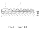
- FIG. 1 shows a schematic cross-sectional view of a conventional composite.
- the conventional composite 1 is artificial leather, including a bottom cloth layer 11, an intermediate layer 12, and a surface layer 13.
- the bottom cloth layer 11 generally is a woven fabric, a nonwoven fabric, leather, a microfiber, or a resin.
- the intermediate layer 12 is formed on the bottom cloth layer 11, and generally is a foam layer.
- the surface layer 13 is located on the intermediate layer 12 and is made of PU resin.
- a texture 14 is formed on the surface of the surface layer 13.
- the texture 14 is a physical texture of bumps and pits which is mostly formed by means of texture contact and transfer, such as printing, embossing, or release paper laminating, or directly polishing the surface of the surface layer 13.
- the above methods of forming a texture have the following shortcomings. First, the methods will influence the surface flatness of the surface layer 13. Second, the pattern of the formed texture is limited, and the 3D textures cannot be achieved.
- the present invention is directed to providing a method of fabricating a resin surface layer, which includes: (a) providing a base, made of a resin and including a plurality of additive particles randomly distributed in the base; (b) changing the orientation of he additive particles to arrange the additive particles in a predetermined form; and (c) drying the base to make a surface of the base exhibit a visual effect of 3D texture.
- a method of fabricating a resin surface layer which includes: (a) providing a base, made of a resin and including a plurality of additive particles randomly distributed in the base; (b) changing the orientation of he additive particles to arrange the additive particles in a predetermined form; and (c) drying the base to make a surface of the base exhibit a visual effect of 3D texture.
- the visual effect of any 3D textures can be achieved by controlling the orientation of the additive particles.
- the present invention is further directed to providing a resin surface layer, which includes a base and a plurality of additive particles.
- the base has a surface and is made of a resin.
- the additive particles are arranged in a predetermined form instead of randomly distributed in the base, so that the surface of the base exhibits a visual effect of 3D texture.
- the present invention is still directed to provide a composite having the above resin surface layer.
- the present invention relates to a method of fabricating a resin surface layer, which includes the following steps:
- the material of the base in Step (a) is selected from a group consisting of PU, polyethylene (polyvinyl chloride), acrylic resin, polycarbonate, and epoxy resin.
- the additive particles in Step (a) are selected from a group consisting of pigments, dyes, colorants, coloring matters, and pearl powders.
- Step (a) a step of forming the base on a carrier is further included, in which the carrier is selected from a group consisting of a release paper, a woven fabric, a nonwoven fabric, leather, a microfiber, and a resin.
- Step (b) includes applying an energy field to polarize the additive particles, so as to change the orientation of the additive particles.
- polarization refers to the reaction changing the orientation of the additive particles.
- the energy field is selected from a group consisting of light, heat, magnetic field, and electric field.
- orientation refers to the distribution (density) of the additive particles, or the angle of the additive particles.
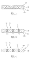
- FIGs. 2 to 4 show schematic views illustrating a method of fabricating a resin surface layer according to a first embodiment of the present invention.
- a base 22 is provided.
- the material of the base 22 is a single-component PU resin (U-BEST POLYMER INDUSTRY CO., LTD®, AT-508ETM).
- the base 22 includes a plurality of additive particles 23.
- the additive particles 23 are pigment particles, and the material of the pigment is 41P series, TAH KONG CHEMICAL INDUSTRIAL CORP.
- the additive particles 23 are randomly distributed in the base 22.
- the base 22 is formed on a release paper (Favini® ASTRAKAN TM ) 21, so that the base 22 has a surface 221.
- a release paper Fevini® ASTRAKAN TM
- the surface 221 of the base 22 is smooth and does not have a physical texture of bumps and pits.
- a magnetic field is applied on the lower surface of the release paper 21 to polarize the additive particles 23, so as to change the distribution of the additive particles 23, so that the additive particles 23 have a predetermined density.
- additive particles 23 are dense in a first region 24, while no additive particle is in a second region 25.
- the base 22 is dried and the release paper 21 is removed, so as to form a surface layer 2.
- the surface 221 of the base 22 can exhibit the visual effect of 3D texture.
- the first region 24 is a bright area
- the second region 25 is a dark area and exhibits a 3D texture of a plurality of cuboids.
- the resin surface layer 2 includes a base 22 and a plurality of additive particles 23.
- the base 22 has a surface 221, and the material of the base 22 is a resin selected from a group consisting of PU, polyethylene (polyvinyl chloride), acrylic resin, polycarbonate, and epoxy resin.
- the material of the base 22 is a single-component PU resin (U-BEST POLYMER INDUSTRY CO., LTD®, AT-508ETM).
- the surface 221 of the base 22 is smooth and does not have the physical texture of bumps and pits.
- the additive particles 23 are located in the base 22.
- the additive particles 23 are selected from a group consisting of pigments, dyes, colorants, coloring matters, and pearl powders.
- the additive particles 23 are pigment particles, and the material of the pigment is 41P series, TAH KONG CHEMICAL INDUSTRIAL CORP.
- the additive particles 23 are arranged in a predetermined form instead of randomly distributed in the base 22, so that the surface 221 of the base 22 can exhibit the visual effect of 3D texture.
- the additive particles 23 have a predetermined density. That is, the density of the additive particles 23 in the first region 24 is different from that of the additive particles 23 in the second region 25, so that the first region 24 is a bright area, and the second region 25 is a dark area and exhibits the 3D texture of cuboids.
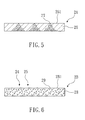
- FIG. 5 shows a schematic view of a resin surface layer according to a second embodiment of the present invention.
- the resin surface layer 2A includes a base 26 and a plurality of additive particles 27.
- the base 26 is the same as the base 22 of the first embodiment.
- the additive particles 27 are substantially the same as the additive particles 23 of the first embodiment, except that the additive particles 27 are arranged into a triangular shape.
- the 3D texture of a plurality of prisms can be seen as if viewed from a surface 261 of the base 26.
- FIG. 6 shows a schematic view of a resin surface layer according to a third embodiment of the present invention.
- the resin surface layer 2B includes a base 28 and a plurality of additive particles 29.
- the base 28 is the same as the base 22 of the first embodiment.
- the additive particles 29 are substantially the same as the additive particles 23 of the first embodiment, except that the orientation of the additive particles 29 is different.
- the angles of the additive particles 29 are changed, so that the additive particles 29 have a predetermined density. As shown in the figure, the angle of the additive particles 29 in the first region 24 is different from the angle of the additive particles 29 in the second region 25.
- the additive particles 29 are uniformly distributed in the base 28, due to the distribution of additive particles at a specific angle, the first region 24 is a bright area, and the second region 25 is a dark area.
- a surface 281 of the base 28 exhibits the 3D texture of a plurality of cuboids, which is the same effect as that of the first embodiment.
- the visual effects of any 3D textures can be achieved by controlling the energy field in order to control the orientation of the additive particles.
- the above resin surface layer may be used alone, or may be used in a layer structure of a composite, which is described in the following embodiments.
- FIGs. 7 and 8 show schematic views of a method of fabricating the composite having a resin surface layer according to the first embodiment of the present invention.
- a release paper (Favini® ASTRAKAN TM ) 31 is provided.
- a base is provided.
- the material of the base is a resin selected from a group consisting of PU, polyethylene (polyvinyl chloride), acrylic resin, polycarbonate, and epoxy resin.
- the base includes a plurality of additive particles selected from the group consisting of pigments, dyes, colorants, coloring matters, and pearl powders. The additive particles are randomly distributed in the base.
- the material of the base is a single-component PU resin (U-BEST POLYMER INDUSTRY CO., LTD®, AT-508ETM).
- the additive particles are pigment particles, and the material of the pigment is 41P series of TAH KONG CHEMICAL INDUSTRIAL CORP.
- the base is formed on the release paper 31 in the weight distribution of 120 g/m 2 .
- an energy field is applied to polarize the additive particles, so as to change the orientation of the additive particles.
- the base is dried to form a surface layer 32 having a surface 321.
- the surface layer 32 is the same as the above resin surface layer.
- an adhesion layer 33 is formed on the surface layer 32.
- the material of the adhesion layer 33 is a two-component PU resin (U-BEST POLYMER INDUSTRY CO., LTD®, BD636MTM), and has a weight distribution of 120 g/m 2 .
- the adhesion layer 33 is dried into a half-dried state at 70°C.
- a bottom cloth layer 34 is formed on the adhesion layer 33, and the bottom cloth layer 34 is selected from a group consisting of a woven fabric, a non-woven fabric, leather, a microfiber, and a resin.
- the bottom cloth layer 34 is artificial leather (San Fang).
- the release paper 31 is removed and inverted 180 degrees, and thus a composite 3 is formed.
- the composite 3 is fabricated by the method of the first embodiment.
- the composite 3 includes a bottom cloth layer 34, an adhesion layer 33, and a surface layer 32.
- the bottom cloth layer 34 is artificial leather (San Fang).
- the adhesion layer 33 is located on the bottom cloth layer 34, and the material of the adhesion layer 33 is a two-component PU resin (U-BEST POLYMER INDUSTRY CO., LTD®, BD636MTM).
- the surface layer 32 is located on the adhesion layer 33.
- the surface layer 32 has a surface 321.
- the surface layer 32 has a base and a plurality of additive particles.
- the material of the base is a resin.
- the additive particles are arranged in a predetermined form instead of randomly distributed in the base, so that the surface 321 of the surface layer 32 can exhibit the visual effect of 3D texture, although the surface 321 is smooth and does not have a physical texture of bumps and pits.
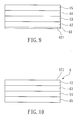
- FIGs. 9 and 10 show schematic views of a method of fabricating the composite having a resin surface layer according to the second embodiment of the present invention.
- a release paper (Favini® ASTRAKAN TM ) 41 is provided.
- a base is provided.
- the material of the base is resin and the base includes a plurality of first additive particles randomly distributed therein.
- the material of the base is a single-component PU resin (U-BEST POLYMER INDUSTRY CO., LTD®, AT-508ETM).
- the first additive particles are pigment particles, and the material of the pigment is 41P series of TAH KONG CHEMICAL INDUSTRIAL CORP.
- the base is formed on the release paper 41 in the weight distribution of 120 g/m 2 .
- an energy field is applied to polarize the first additive particles, so as to change the orientation of the first additive particles.
- the base is dried to form a surface layer 42 having a surface 421.
- the surface layer 42 is the same as the above resin surface layer.
- an intermediate layer 43 is formed on the surface layer 42.
- the material of the intermediate layer 43 is resin and the intermediate layer 43 includes a plurality of second additive particles randomly distributed therein.
- the material of the intermediate layer 43 is selected from a group consisting of PU, polyethylene (polyvinyl chloride), acrylic resin, polycarbonate, and epoxy resin.
- the second additive particles are selected from a group consisting of pigments, dyes, colorants, coloring matters, and pearl powders.
- the material of the intermediate layer 43 is a single-component PU resin (U-BEST POLYMER INDUSTRY CO., LTD®, AT-508ETM).
- the second additive particles are pigment particles, and the material of the pigment is 41P series of TAH KONG CHEMICAL INDUSTRIAL CORP.
- the intermediate layer 43 is formed on the surface layer 42 in the weight distribution of 120 g/m 2 . It should be noted that the intermediate layer 43 can be directly dried without polarization.
- an adhesion layer 44 is formed on the intermediate layer 43.
- the material of the adhesion layer 44 is a two-component PU resin (U-BEST POLYMER INDUSTRY CO., LTD®, BD636MTM), and has the weight distribution of 120 g/m 2 .
- the adhesion layer 44 is dried into a half-dried state at 70°C.
- a bottom cloth layer 45 is formed on the adhesion layer 44, and the bottom cloth layer 45 is selected from a group consisting of a woven fabric, a non-woven fabric, leather, a microfiber, and a resin.
- the bottom cloth layer 45 is artificial leather (San Fang).
- the release paper 41 is removed and inverted 180 degrees, thus forming a composite 4.
- the composite 4 is fabricated by the method of the second embodiment and is substantially the same as the composite 3 of the first embodiment, except that the composite 4 further has an intermediate layer 43 between the surface layer 42 and the adhesion layer 44.
- the material of the intermediate layer 43 is resin, and the intermediate layer 43 includes a plurality of second additive particles randomly distributed therein.
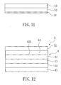
- FIGs. 11 and 12 show schematic views of a method of fabricating the composite having a resin surface layer according to the third embodiment of the present invention.
- the fabrication method of this embodiment occurs subsequent to the second embodiment.
- a second release paper (Favini® ASTRAKAN TM ) 51 is provided.
- a top layer 52 is formed on the second release paper 51.
- the material of the top layer 52 is resin and the top layer 52 includes a plurality of third additive particles randomly distributed therein.
- the material of the top layer 52 is selected from a group consisting of PU, polyethylene (polyvinyl chloride), acrylic resin, polycarbonate, and epoxy resin.
- the third additive particles are selected from the group consisting of pigments, dyes, colorants, coloring matters, and pearl powders.
- the material of the top layer 52 is a single-component PU resin (U-BEST POLYMER INDUSTRY CO., LTD®, AT-508ETM).
- the third additive particles are pigment particles, and the material of the pigment is 41P series of TAH KONG CHEMICAL INDUSTRIAL CORP.
- the top layer 52 is formed on the second release paper 51 in the weight distribution of 120 g/m 2 . It should be noted that the top layer 52 can be directly dried without polarization, and the third additive particles are required to have transparency.
- a second adhesion layer 53 is formed on the top layer 52.
- the material of the second adhesion layer 53 is a two-component PU resin (U-BEST POLYMER INDUSTRY CO., LTD®, BD636MTM), and has a weight distribution of 120 g/m 2 . Thereafter, the second adhesion layer 53 is dried into a half-dried state at 70°C.
- the second release paper 51, the top layer 52, and the second adhesion layer 53 are inverted, so as to adhere the second release paper 51 and the top layer 52 to the surface layer 42 of the composite 4 of the second embodiment by the use of the second adhesion layer 53. Finally, the second release paper 51 is removed, thus obtaining a composite 5.
- FIG. 12 a schematic view of a composite having a resin surface layer according to the third embodiment of the present invention is shown.
- the composite 5 is fabricated by the method of the third embodiment.
- the composite 5 is substantially the same as the composite 4 of the second embodiment, except that the composite 5 further has a top layer 52 and a second adhesion layer 53.
- the second adhesion layer 53 is located on the surface layer 42, and the top layer 52 is located on the second adhesion layer 53.
- the material of the top layer 52 is resin, and the top layer 52 includes a plurality of third additive particles randomly distributed therein.
- the third additive particles are required to have transparency.
- FIGs. 13 and 15 show schematic views of a method of fabricating the composite having a resin surface layer according to the fourth embodiment of the present invention.
- a bottom cloth layer 61 is provided.
- the bottom cloth layer 61 is selected from a group consisting of a woven fabric, a non-woven fabric, leather, a microfiber, and a resin.
- the bottom cloth layer 61 is artificial leather (San Fang).
- the material of the base is a resin selected from the group consisting of PU, polyethylene (polyvinyl chloride), acrylic resin, polycarbonate, and epoxy resin.
- the base includes a plurality of first additive particles, and the first additive particles are selected from the group consisting of pigments, dyes, colorants, coloring matters, and pearl powders.
- the first additive particles are randomly distributed in the base.
- the material of the base is a single-component PU resin (U-BEST POLYMER INDUSTRY CO., LTD®, AT-508ETM).
- the first additive particles are pigment particles, and the material of the pigment is 41P series of TAH KONG CHEMICAL INDUSTRIAL CORP.
- the base is formed on the bottom cloth layer 61 in the weight distribution of 120 g/m 2 .
- an energy field is applied to polarize the first additive particles, so as to change the orientation of the first additive particles.
- the base is dried to form a surface layer 62 having a surface 621.
- the surface layer 62 is the same as the above resin surface layer.
- a release paper (Favini® ASTRAKAN TM ) 63 is provided. Then, a top layer 64 is formed on the release paper 63.
- the material of the top layer 64 is resin, and the top layer 64 includes a plurality of second additive particles randomly distributed therein.
- the material of the top layer 64 is selected from a group consisting of PU, polyethylene (polyvinyl chloride), acrylic resin, polycarbonate, and epoxy resin.
- the second additive particles are selected from a group consisting of pigments, dyes, colorants, coloring matters, and pearl powders.
- the material of the top layer 64 is a single-component PU resin (U-BEST POLYMER INDUSTRY CO., LTD®, AT-508ETM).
- the second additive particles are pigment particles, and the material of the pigment is 41P series of TAH KONG CHEMICAL INDUSTRIAL CORP.
- the top layer 64 is formed on the release paper 63 in the weight distribution of 120 g/m 2 . It should be noted that the top layer 64 can be directly dried without polarization, and the second additive particles are required to have transparency.
- an adhesion layer 65 is formed on the top layer 64.
- the material of the adhesion layer 65 is a two-component PU resin (U-BEST POLYMER INDUSTRY CO., LTD®, BD636MTM), and has a weight distribution of 120 g/m 2 . Thereafter, the adhesion layer 65 is dried into a half-dried state at 70°C.
- the release paper 63, the top layer 64, and the adhesion layer 65 are inverted, so as to adhere the release paper 63 and the top layer 64 to the surface 621 of the surface layer 62 by the use of the adhesion layer 65. Finally, the release paper 63 is removed, thus obtaining a composite 6.
- the composite 6 is fabricated by the method of the third embodiment.
- the composite 6 includes a bottom cloth layer 61, a surface layer 62, an adhesion layer 65, and a top layer 64.
- the bottom cloth layer 61 is artificial leather (San Fang).
- the surface layer 62 is located on the bottom cloth layer 61.
- the surface layer 62 has a surface 621.
- the surface layer 62 has a base and a plurality of first additive particles.
- the material of the base is a resin
- the first additive particles are arranged in a predetermined form instead of randomly distributed in the base, so that the surface 621 of the surface layer 62 can exhibit the visual effect of 3D texture, although the surface 621 of the surface layer 62 is smooth and does not have a physical texture of bumps and pits.
- the adhesion layer 65 is located on the surface layer 62, and the material of the adhesion layer 65 is a two-component PU resin (U-BEST POLYMER INDUSTRY CO., LTD®, BD636MTM).
- the top layer 64 is located on the adhesion layer 65.
- the material of the top layer 64 is resin, and the top layer 64 includes a plurality of second additive particles randomly distributed therein. The second additive particles are required to have transparency.
Landscapes
- Engineering & Computer Science (AREA)
- Textile Engineering (AREA)
- Mechanical Engineering (AREA)
- Ceramic Engineering (AREA)
- Chemical & Material Sciences (AREA)
- Organic Chemistry (AREA)
- Power Engineering (AREA)
- Laminated Bodies (AREA)
Abstract
Description
- The present invention relates to a resin surface layer and a method of fabricating the same. More particularly, the present invention relates to a resin surface layer not having a physical texture of bumps and pits but capable of exhibiting a visual effect of 3D texture and a method of fabricating the same.
-
FIG. 1 shows a schematic cross-sectional view of a conventional composite. Theconventional composite 1 is artificial leather, including a bottom cloth layer 11, anintermediate layer 12, and asurface layer 13. The bottom cloth layer 11 generally is a woven fabric, a nonwoven fabric, leather, a microfiber, or a resin. Theintermediate layer 12 is formed on the bottom cloth layer 11, and generally is a foam layer. Thesurface layer 13 is located on theintermediate layer 12 and is made of PU resin. - In order to improve the real-life quality of the
conventional composite 1, atexture 14 is formed on the surface of thesurface layer 13. Thetexture 14 is a physical texture of bumps and pits which is mostly formed by means of texture contact and transfer, such as printing, embossing, or release paper laminating, or directly polishing the surface of thesurface layer 13. However, the above methods of forming a texture have the following shortcomings. First, the methods will influence the surface flatness of thesurface layer 13. Second, the pattern of the formed texture is limited, and the 3D textures cannot be achieved. - Therefore, it is necessary to provide a resin surface layer and a method of fabricating the same to solve the above problems.
- The present invention is directed to providing a method of fabricating a resin surface layer, which includes: (a) providing a base, made of a resin and including a plurality of additive particles randomly distributed in the base; (b) changing the orientation of he additive particles to arrange the additive particles in a predetermined form; and (c) drying the base to make a surface of the base exhibit a visual effect of 3D texture. Thus, the visual effect of any 3D textures can be achieved by controlling the orientation of the additive particles.
- The present invention is further directed to providing a resin surface layer, which includes a base and a plurality of additive particles. The base has a surface and is made of a resin. The additive particles are arranged in a predetermined form instead of randomly distributed in the base, so that the surface of the base exhibits a visual effect of 3D texture.
- The present invention is still directed to provide a composite having the above resin surface layer.
-
-
FIG. 1 is a schematic cross-sectional view of a conventional composite; -
FIGs. 2 to 4 are schematic views illustrating a method of fabricating a resin surface layer according to a first embodiment of the present invention; -
FIG. 5 is a schematic view of a resin surface layer according to a second embodiment of the present invention; -
FIG. 6 is a schematic view illustrating a resin surface layer according to a third embodiment of the present invention; -
FIGs. 7 and 8 are schematic views illustrating a method of fabricating the composite having a resin surface layer according to the first embodiment of the present invention; -
FIGs. 9 and 10 are schematic views illustrating a method of fabricating the composite having a resin surface layer according to the second embodiment of the present invention; -
FIGs. 11 and 12 are schematic views illustrating a method of fabricating the composite having a resin surface layer according to the third embodiment of the present invention; and - FIGs. 13 to 15 are schematic views of a method of fabricating the composite having a resin surface layer according to the fourth embodiment of the present invention.
- The present invention relates to a method of fabricating a resin surface layer, which includes the following steps:
- (a) providing a base, made of a resin and including a plurality of additive particles randomly distributed in the base;
- (b) changing the orientation of the additive particles to arrange the additive particles in a predetermined form; and
- (c) drying the base to make a surface of the base exhibit a visual effect of 3D texture.
- In the present invention, the material of the base in Step (a) is selected from a group consisting of PU, polyethylene (polyvinyl chloride), acrylic resin, polycarbonate, and epoxy resin. The additive particles in Step (a) are selected from a group consisting of pigments, dyes, colorants, coloring matters, and pearl powders.
- In a preferred embodiment, after Step (a), a step of forming the base on a carrier is further included, in which the carrier is selected from a group consisting of a release paper, a woven fabric, a nonwoven fabric, leather, a microfiber, and a resin.
- In the present invention, Step (b) includes applying an energy field to polarize the additive particles, so as to change the orientation of the additive particles. As used in the present invention, the word "polarization" refers to the reaction changing the orientation of the additive particles. The energy field is selected from a group consisting of light, heat, magnetic field, and electric field. As used herein, the word "orientation" refers to the distribution (density) of the additive particles, or the angle of the additive particles.
-
FIGs. 2 to 4 show schematic views illustrating a method of fabricating a resin surface layer according to a first embodiment of the present invention. First, referring toFIG. 2 , abase 22 is provided. The material of thebase 22 is a single-component PU resin (U-BEST POLYMER INDUSTRY CO., LTD®, AT-508E™). Thebase 22 includes a plurality ofadditive particles 23. In this embodiment, theadditive particles 23 are pigment particles, and the material of the pigment is 41P series, TAH KONG CHEMICAL INDUSTRIAL CORP. Theadditive particles 23 are randomly distributed in thebase 22. - Thereafter, the
base 22 is formed on a release paper (Favini® ASTRAKAN™) 21, so that thebase 22 has asurface 221. As the surface of therelease paper 21 does not have textures, thesurface 221 of thebase 22 is smooth and does not have a physical texture of bumps and pits. - Then, referring to
FIG. 3 , a magnetic field is applied on the lower surface of therelease paper 21 to polarize theadditive particles 23, so as to change the distribution of theadditive particles 23, so that theadditive particles 23 have a predetermined density. As shown in the figure,additive particles 23 are dense in afirst region 24, while no additive particle is in asecond region 25. - Next, referring to
FIG. 4 , thebase 22 is dried and therelease paper 21 is removed, so as to form asurface layer 2. After inverting thebase 22, thesurface 221 of thebase 22 can exhibit the visual effect of 3D texture. As shown in the figure, thefirst region 24 is a bright area, and thesecond region 25 is a dark area and exhibits a 3D texture of a plurality of cuboids. - Referring to
FIG. 4 again, a schematic view of a resin surface layer according to the first embodiment of the present invention is shown. Theresin surface layer 2 includes abase 22 and a plurality ofadditive particles 23. Thebase 22 has asurface 221, and the material of thebase 22 is a resin selected from a group consisting of PU, polyethylene (polyvinyl chloride), acrylic resin, polycarbonate, and epoxy resin. In this embodiment, the material of thebase 22 is a single-component PU resin (U-BEST POLYMER INDUSTRY CO., LTD®, AT-508E™). Thesurface 221 of thebase 22 is smooth and does not have the physical texture of bumps and pits. - The
additive particles 23 are located in thebase 22. Theadditive particles 23 are selected from a group consisting of pigments, dyes, colorants, coloring matters, and pearl powders. In this embodiment, theadditive particles 23 are pigment particles, and the material of the pigment is 41P series, TAH KONG CHEMICAL INDUSTRIAL CORP. Theadditive particles 23 are arranged in a predetermined form instead of randomly distributed in thebase 22, so that thesurface 221 of the base 22 can exhibit the visual effect of 3D texture. In this embodiment, theadditive particles 23 have a predetermined density. That is, the density of theadditive particles 23 in thefirst region 24 is different from that of theadditive particles 23 in thesecond region 25, so that thefirst region 24 is a bright area, and thesecond region 25 is a dark area and exhibits the 3D texture of cuboids. -
FIG. 5 shows a schematic view of a resin surface layer according to a second embodiment of the present invention. Theresin surface layer 2A includes abase 26 and a plurality ofadditive particles 27. Thebase 26 is the same as thebase 22 of the first embodiment. Theadditive particles 27 are substantially the same as theadditive particles 23 of the first embodiment, except that theadditive particles 27 are arranged into a triangular shape. Thus, the 3D texture of a plurality of prisms can be seen as if viewed from asurface 261 of thebase 26. -
FIG. 6 shows a schematic view of a resin surface layer according to a third embodiment of the present invention. Theresin surface layer 2B includes abase 28 and a plurality ofadditive particles 29. Thebase 28 is the same as thebase 22 of the first embodiment. Theadditive particles 29 are substantially the same as theadditive particles 23 of the first embodiment, except that the orientation of theadditive particles 29 is different. In this embodiment, after theadditive particles 29 are polarized, the angles of theadditive particles 29 are changed, so that theadditive particles 29 have a predetermined density. As shown in the figure, the angle of theadditive particles 29 in thefirst region 24 is different from the angle of theadditive particles 29 in thesecond region 25. Therefore, although theadditive particles 29 are uniformly distributed in thebase 28, due to the distribution of additive particles at a specific angle, thefirst region 24 is a bright area, and thesecond region 25 is a dark area. Thus, asurface 281 of the base 28 exhibits the 3D texture of a plurality of cuboids, which is the same effect as that of the first embodiment. - Accordingly, in the present invention, the visual effects of any 3D textures can be achieved by controlling the energy field in order to control the orientation of the additive particles.
- The above resin surface layer may be used alone, or may be used in a layer structure of a composite, which is described in the following embodiments.
-
FIGs. 7 and 8 show schematic views of a method of fabricating the composite having a resin surface layer according to the first embodiment of the present invention. First, referring toFIG. 7 , a release paper (Favini® ASTRAKAN™) 31 is provided. Next, a base is provided. The material of the base is a resin selected from a group consisting of PU, polyethylene (polyvinyl chloride), acrylic resin, polycarbonate, and epoxy resin. The base includes a plurality of additive particles selected from the group consisting of pigments, dyes, colorants, coloring matters, and pearl powders. The additive particles are randomly distributed in the base. In this embodiment, the material of the base is a single-component PU resin (U-BEST POLYMER INDUSTRY CO., LTD®, AT-508E™). The additive particles are pigment particles, and the material of the pigment is 41P series of TAH KONG CHEMICAL INDUSTRIAL CORP. - Then, the base is formed on the
release paper 31 in the weight distribution of 120 g/m2. After that, similar to the above, an energy field is applied to polarize the additive particles, so as to change the orientation of the additive particles. Next, the base is dried to form asurface layer 32 having asurface 321. Thesurface layer 32 is the same as the above resin surface layer. - Next, an
adhesion layer 33 is formed on thesurface layer 32. The material of theadhesion layer 33 is a two-component PU resin (U-BEST POLYMER INDUSTRY CO., LTD®, BD636M™), and has a weight distribution of 120 g/m2. Then, theadhesion layer 33 is dried into a half-dried state at 70°C. After that, abottom cloth layer 34 is formed on theadhesion layer 33, and thebottom cloth layer 34 is selected from a group consisting of a woven fabric, a non-woven fabric, leather, a microfiber, and a resin. In this embodiment, thebottom cloth layer 34 is artificial leather (San Fang). Finally, referring toFIG. 8 , therelease paper 31 is removed and inverted 180 degrees, and thus acomposite 3 is formed. - Referring to
FIG. 8 again, a schematic view of a composite having a resin surface layer according to the first embodiment of the present invention is shown. Thecomposite 3 is fabricated by the method of the first embodiment. Thecomposite 3 includes abottom cloth layer 34, anadhesion layer 33, and asurface layer 32. Thebottom cloth layer 34 is artificial leather (San Fang). Theadhesion layer 33 is located on thebottom cloth layer 34, and the material of theadhesion layer 33 is a two-component PU resin (U-BEST POLYMER INDUSTRY CO., LTD®, BD636MTM). Thesurface layer 32 is located on theadhesion layer 33. Thesurface layer 32 has asurface 321. Thesurface layer 32 has a base and a plurality of additive particles. The material of the base is a resin. The additive particles are arranged in a predetermined form instead of randomly distributed in the base, so that thesurface 321 of thesurface layer 32 can exhibit the visual effect of 3D texture, although thesurface 321 is smooth and does not have a physical texture of bumps and pits. -
FIGs. 9 and 10 show schematic views of a method of fabricating the composite having a resin surface layer according to the second embodiment of the present invention. First, referring toFIG. 9 , a release paper (Favini® ASTRAKAN™) 41 is provided. Next, a base is provided. The material of the base is resin and the base includes a plurality of first additive particles randomly distributed therein. In this embodiment, the material of the base is a single-component PU resin (U-BEST POLYMER INDUSTRY CO., LTD®, AT-508E™). The first additive particles are pigment particles, and the material of the pigment is 41P series of TAH KONG CHEMICAL INDUSTRIAL CORP. - Then, the base is formed on the
release paper 41 in the weight distribution of 120 g/m2. After that, similar to the above, an energy field is applied to polarize the first additive particles, so as to change the orientation of the first additive particles. Next, the base is dried to form asurface layer 42 having asurface 421. Thesurface layer 42 is the same as the above resin surface layer. - Next, an
intermediate layer 43 is formed on thesurface layer 42. The material of theintermediate layer 43 is resin and theintermediate layer 43 includes a plurality of second additive particles randomly distributed therein. The material of theintermediate layer 43 is selected from a group consisting of PU, polyethylene (polyvinyl chloride), acrylic resin, polycarbonate, and epoxy resin. The second additive particles are selected from a group consisting of pigments, dyes, colorants, coloring matters, and pearl powders. In this embodiment, the material of theintermediate layer 43 is a single-component PU resin (U-BEST POLYMER INDUSTRY CO., LTD®, AT-508E™). The second additive particles are pigment particles, and the material of the pigment is 41P series of TAH KONG CHEMICAL INDUSTRIAL CORP. Next, theintermediate layer 43 is formed on thesurface layer 42 in the weight distribution of 120 g/m2. It should be noted that theintermediate layer 43 can be directly dried without polarization. - Next, an
adhesion layer 44 is formed on theintermediate layer 43. The material of theadhesion layer 44 is a two-component PU resin (U-BEST POLYMER INDUSTRY CO., LTD®, BD636M™), and has the weight distribution of 120 g/m2. Thereafter, theadhesion layer 44 is dried into a half-dried state at 70°C. Next, abottom cloth layer 45 is formed on theadhesion layer 44, and thebottom cloth layer 45 is selected from a group consisting of a woven fabric, a non-woven fabric, leather, a microfiber, and a resin. In this embodiment, thebottom cloth layer 45 is artificial leather (San Fang). Finally, referring toFIG. 10 , therelease paper 41 is removed and inverted 180 degrees, thus forming acomposite 4. - Referring to
FIG. 10 again, a composite having a resin surface layer according to the second embodiment of the present invention is shown. Thecomposite 4 is fabricated by the method of the second embodiment and is substantially the same as thecomposite 3 of the first embodiment, except that the composite 4 further has anintermediate layer 43 between thesurface layer 42 and theadhesion layer 44. The material of theintermediate layer 43 is resin, and theintermediate layer 43 includes a plurality of second additive particles randomly distributed therein. -
FIGs. 11 and 12 show schematic views of a method of fabricating the composite having a resin surface layer according to the third embodiment of the present invention. The fabrication method of this embodiment occurs subsequent to the second embodiment. First, referring toFIG. 11 , a second release paper (Favini® ASTRAKAN™) 51 is provided. Next, atop layer 52 is formed on thesecond release paper 51. The material of thetop layer 52 is resin and thetop layer 52 includes a plurality of third additive particles randomly distributed therein. The material of thetop layer 52 is selected from a group consisting of PU, polyethylene (polyvinyl chloride), acrylic resin, polycarbonate, and epoxy resin. The third additive particles are selected from the group consisting of pigments, dyes, colorants, coloring matters, and pearl powders. In this embodiment, the material of thetop layer 52 is a single-component PU resin (U-BEST POLYMER INDUSTRY CO., LTD®, AT-508E™). The third additive particles are pigment particles, and the material of the pigment is 41P series of TAH KONG CHEMICAL INDUSTRIAL CORP. Next, thetop layer 52 is formed on thesecond release paper 51 in the weight distribution of 120 g/m2. It should be noted that thetop layer 52 can be directly dried without polarization, and the third additive particles are required to have transparency. - Next, a
second adhesion layer 53 is formed on thetop layer 52. The material of thesecond adhesion layer 53 is a two-component PU resin (U-BEST POLYMER INDUSTRY CO., LTD®, BD636M™), and has a weight distribution of 120 g/m2. Thereafter, thesecond adhesion layer 53 is dried into a half-dried state at 70°C. - Then, the
second release paper 51, thetop layer 52, and thesecond adhesion layer 53 are inverted, so as to adhere thesecond release paper 51 and thetop layer 52 to thesurface layer 42 of thecomposite 4 of the second embodiment by the use of thesecond adhesion layer 53. Finally, thesecond release paper 51 is removed, thus obtaining acomposite 5. - Referring to
FIG. 12 again, a schematic view of a composite having a resin surface layer according to the third embodiment of the present invention is shown. Thecomposite 5 is fabricated by the method of the third embodiment. Thecomposite 5 is substantially the same as thecomposite 4 of the second embodiment, except that the composite 5 further has atop layer 52 and asecond adhesion layer 53. Thesecond adhesion layer 53 is located on thesurface layer 42, and thetop layer 52 is located on thesecond adhesion layer 53. The material of thetop layer 52 is resin, and thetop layer 52 includes a plurality of third additive particles randomly distributed therein. The third additive particles are required to have transparency. - FIGs. 13 and 15 show schematic views of a method of fabricating the composite having a resin surface layer according to the fourth embodiment of the present invention. First, referring to FIG. 13, a bottom cloth layer 61 is provided. The bottom cloth layer 61 is selected from a group consisting of a woven fabric, a non-woven fabric, leather, a microfiber, and a resin. In this embodiment, the bottom cloth layer 61 is artificial leather (San Fang).
- Next, a base is provided. The material of the base is a resin selected from the group consisting of PU, polyethylene (polyvinyl chloride), acrylic resin, polycarbonate, and epoxy resin. The base includes a plurality of first additive particles, and the first additive particles are selected from the group consisting of pigments, dyes, colorants, coloring matters, and pearl powders. The first additive particles are randomly distributed in the base. In this embodiment, the material of the base is a single-component PU resin (U-BEST POLYMER INDUSTRY CO., LTD®, AT-508E™). The first additive particles are pigment particles, and the material of the pigment is 41P series of TAH KONG CHEMICAL INDUSTRIAL CORP.
- Then, the base is formed on the bottom cloth layer 61 in the weight distribution of 120 g/m2. After that, similar to the above, an energy field is applied to polarize the first additive particles, so as to change the orientation of the first additive particles. Next, the base is dried to form a surface layer 62 having a surface 621. The surface layer 62 is the same as the above resin surface layer.
- Next, referring to FIG. 14, a release paper (Favini® ASTRAKAN™) 63 is provided. Then, a top layer 64 is formed on the release paper 63. The material of the top layer 64 is resin, and the top layer 64 includes a plurality of second additive particles randomly distributed therein. The material of the top layer 64 is selected from a group consisting of PU, polyethylene (polyvinyl chloride), acrylic resin, polycarbonate, and epoxy resin. The second additive particles are selected from a group consisting of pigments, dyes, colorants, coloring matters, and pearl powders. In this embodiment, the material of the top layer 64 is a single-component PU resin (U-BEST POLYMER INDUSTRY CO., LTD®, AT-508E™). The second additive particles are pigment particles, and the material of the pigment is 41P series of TAH KONG CHEMICAL INDUSTRIAL CORP. Next, the top layer 64 is formed on the release paper 63 in the weight distribution of 120 g/m2. It should be noted that the top layer 64 can be directly dried without polarization, and the second additive particles are required to have transparency.
- Next, an adhesion layer 65 is formed on the top layer 64. The material of the adhesion layer 65 is a two-component PU resin (U-BEST POLYMER INDUSTRY CO., LTD®, BD636M™), and has a weight distribution of 120 g/m2. Thereafter, the adhesion layer 65 is dried into a half-dried state at 70°C.
- Next, referring to FIG. 15, the release paper 63, the top layer 64, and the adhesion layer 65 are inverted, so as to adhere the release paper 63 and the top layer 64 to the surface 621 of the surface layer 62 by the use of the adhesion layer 65. Finally, the release paper 63 is removed, thus obtaining a composite 6.
- Referring to FIG. 15 again, a composite having a resin surface layer according to the third embodiment of the present invention is shown. The composite 6 is fabricated by the method of the third embodiment. The composite 6 includes a bottom cloth layer 61, a surface layer 62, an adhesion layer 65, and a top layer 64. The bottom cloth layer 61 is artificial leather (San Fang). The surface layer 62 is located on the bottom cloth layer 61. The surface layer 62 has a surface 621. The surface layer 62 has a base and a plurality of first additive particles. The material of the base is a resin, the first additive particles are arranged in a predetermined form instead of randomly distributed in the base, so that the surface 621 of the surface layer 62 can exhibit the visual effect of 3D texture, although the surface 621 of the surface layer 62 is smooth and does not have a physical texture of bumps and pits.
- The adhesion layer 65 is located on the surface layer 62, and the material of the adhesion layer 65 is a two-component PU resin (U-BEST POLYMER INDUSTRY CO., LTD®, BD636M™). The top layer 64 is located on the adhesion layer 65. The material of the top layer 64 is resin, and the top layer 64 includes a plurality of second additive particles randomly distributed therein. The second additive particles are required to have transparency.
- While several embodiments of the present invention have been illustrated and described, various modifications and improvements can be made by those skilled in the art. The embodiments of the present invention are therefore described in an illustrative but not restrictive sense. It is intended that the present invention should not be limited to the particular forms as illustrated, and that all modifications which maintain the spirit and scope of the present invention are within the scope defined in the appended claims.
Claims (15)
- A method of fabricating a resin surface layer, comprising:(a) providing a base (22, 26, 28), made of a resin and including a plurality of additive particles (23, 27, 29) randomly distributed in the base;(b) changing an orientation of the additive particles, so that the additive particles are arranged in a predetermined form; and(c) drying the base to make a surface (221, 261, 281) of the base exhibit a visual effect of 3D texture.
- The method as claimed in Claim 1, wherein the material of the base (22, 26, 28) of Step (a) is selected from a group consisting of PU, polyethylene (polyvinyl chloride), acrylic resin, polycarbonate, and epoxy resin, and the additive particles (23, 27, 29) are selected from a group consisting of pigments, dyes, colorants, coloring matters, and pearl powders.
- The method as claimed in Claim 1 or 2, after Step (a), further comprising a step of forming the base on a carrier (21).
- The method as claimed in any of the preceding claims, wherein in Step (b), an energy field is applied to polarize the additive particles (23, 27, 29), so as to change the orientation of the additive particles, and the energy field is selected from a group consisting of light, heat, magnetic field, and electric field.
- The method as claimed in any of the preceding claims, wherein in Step (b), the distribution of the additive particles (23, 27, 29) is changed, so that the additive particles have a predetermined density.
- The method as claimed in any of claims 1 to 4, wherein in Step (b), an angle of the additive particles (23, 27, 29) is changed, so that the additive particles are uniformly distributed in the base and have a predetermined angle distribution.
- A resin surface layer, comprising:a base (22, 26, 28), having a surface and made of a resin; anda plurality of additive particles (23, 27, 29), located in the base, arranged in a predetermined form instead of being randomly distributed in the base, so that the surface (221, 261, 281) of the base exhibits a visual effect of 3D texture.
- A method of fabricating a composite having a resin surface layer, comprising:(a) providing a release paper;(b) performing the steps according to any of claims 1 to 6, wherein the base is formed on the release paper;(c) forming a first adhesion layer (33) on the surface layer;(d) forming a bottom cloth layer (34) on the first adhesion layer; and(e) removing the release paper (31, 41) to form said composite.
- The method as claimed in Claim 8, further comprising a step of forming an intermediate layer on the surface layer, wherein the adhesion layer is formed on the intermediate layer (43) in Step (c).
- The method as claimed in Claim 9, wherein the material of the intermediate layer is resin and the intermediate layer comprises a plurality of second additive particles randomly distributed therein.
- The method as claimed in any of claims 8 to 10, after Step (e), further comprising:(f) providing a second release paper;(g) forming a top layer on the second release paper;(h) forming a second adhesion layer on the top layer;(k) adhering the second adhesion layer to the surface layer of the composite, so that the second release paper and the top layer are adhered to the surface layer of the composite; and(1) removing the second release paper.
- The method as claimed in Claim 11, wherein the material of the top layer is resin and the top layer comprises a plurality of third additive particles randomly distributed therein.
- A composite having a resin surface layer, comprising:a bottom cloth layer, selected from a group consisting of a woven fabric, a non-woven fabric, leather, a microfiber, and a resin;an adhesion layer, located on the bottom cloth layer; anda resin surface layer as claimed in claim 7 located on the adhesion layer.
- The composite as claimed in Claim 13, wherein the additive particles are selected from a group consisting of pigments, dyes, colorants, coloring matters, and pearl powders, the composite further comprises an intermediate layer between the surface layer and the adhesion layer, and the material of the intermediate layer is resin and the intermediate layer comprises a plurality of second additive particles randomly distributed therein.
- The composite as claimed in Claim 14, further comprising a second adhesion layer and a top layer, wherein the second adhesion layer is located on the surface layer, and the top layer is located on the second adhesion layer, the material of the top layer is resin, and a plurality of third additive particles is randomly distributed in the top layer.
Applications Claiming Priority (1)
| Application Number | Priority Date | Filing Date | Title |
|---|---|---|---|
| TW096132988A TW200911525A (en) | 2007-09-05 | 2007-09-05 | Resin surface layer and method of fabricating the same, composite having the resin surface layer and method of fabricating the same |
Publications (3)
| Publication Number | Publication Date |
|---|---|
| EP2033770A2 true EP2033770A2 (en) | 2009-03-11 |
| EP2033770A3 EP2033770A3 (en) | 2010-03-10 |
| EP2033770B1 EP2033770B1 (en) | 2012-06-27 |
Family
ID=40193489
Family Applications (1)
| Application Number | Title | Priority Date | Filing Date |
|---|---|---|---|
| EP08100124A Ceased EP2033770B1 (en) | 2007-09-05 | 2008-01-04 | Resin surface layer having a visual effect of 3D structure and method of fabricating the same, composite having the resin surface layer and method of fabricating the same |
Country Status (3)
| Country | Link |
|---|---|
| US (2) | US20090061155A1 (en) |
| EP (1) | EP2033770B1 (en) |
| TW (1) | TW200911525A (en) |
Cited By (1)
| Publication number | Priority date | Publication date | Assignee | Title |
|---|---|---|---|---|
| EP3266583A1 (en) * | 2016-06-15 | 2018-01-10 | Renolit SE | Effect films and method for preparation |
Families Citing this family (3)
| Publication number | Priority date | Publication date | Assignee | Title |
|---|---|---|---|---|
| TW200948631A (en) * | 2008-05-26 | 2009-12-01 | San Fang Chemical Industry Co | Resin cover layer, method for manufacturing the same, composite material having the same and method for manufacturing the composition material |
| TWI717208B (en) | 2020-02-07 | 2021-01-21 | 南亞塑膠工業股份有限公司 | Release liner and method for producing the same |
| CN114211004B (en) * | 2021-12-17 | 2024-01-12 | 北京工商大学 | PVA-based composite film layer on the surface of 3D printed stainless steel workpiece and its preparation method |
Family Cites Families (8)
| Publication number | Priority date | Publication date | Assignee | Title |
|---|---|---|---|---|
| US3507938A (en) * | 1963-04-04 | 1970-04-21 | Heinz Hundsdiecker | Method for producing shaped articles of hardened synthetic resin having a pigment pattern incorporated therein |
| DE69218582T2 (en) * | 1992-02-21 | 1997-07-10 | Hashimoto Forming Kogyo Co | Painting with magnetically produced pattern and lacquered product with magnetically produced pattern |
| DE4419173A1 (en) * | 1994-06-01 | 1995-12-07 | Basf Ag | Magnetizable multi-coated metallic gloss pigments |
| GB2400315B (en) * | 2003-04-11 | 2005-11-02 | Milliken Ind Ltd | Patterned square carpet tiles |
| TWI285697B (en) * | 2003-12-29 | 2007-08-21 | San Fang Chemical Industry Co | Flameproof environmentally friendly artificial leather and process for making the same |
| US20060272770A1 (en) * | 2004-08-24 | 2006-12-07 | San Fang Chemical Industry Co., Ltd. | Method for making artificial leather with superficial texture |
| JP5129935B2 (en) * | 2006-06-13 | 2013-01-30 | 日東電工株式会社 | Sheet-like composite material and manufacturing method thereof |
| TW200948631A (en) * | 2008-05-26 | 2009-12-01 | San Fang Chemical Industry Co | Resin cover layer, method for manufacturing the same, composite material having the same and method for manufacturing the composition material |
-
2007
- 2007-09-05 TW TW096132988A patent/TW200911525A/en not_active IP Right Cessation
- 2007-12-19 US US11/959,609 patent/US20090061155A1/en not_active Abandoned
-
2008
- 2008-01-04 EP EP08100124A patent/EP2033770B1/en not_active Ceased
-
2011
- 2011-08-04 US US13/197,927 patent/US20110311772A1/en not_active Abandoned
Non-Patent Citations (1)
| Title |
|---|
| None |
Cited By (1)
| Publication number | Priority date | Publication date | Assignee | Title |
|---|---|---|---|---|
| EP3266583A1 (en) * | 2016-06-15 | 2018-01-10 | Renolit SE | Effect films and method for preparation |
Also Published As
| Publication number | Publication date |
|---|---|
| TW200911525A (en) | 2009-03-16 |
| US20110311772A1 (en) | 2011-12-22 |
| TWI348421B (en) | 2011-09-11 |
| US20090061155A1 (en) | 2009-03-05 |
| EP2033770A3 (en) | 2010-03-10 |
| EP2033770B1 (en) | 2012-06-27 |
Similar Documents
| Publication | Publication Date | Title |
|---|---|---|
| TWI482836B (en) | Laminating film | |
| CN102439223B (en) | A kind of applique and making and use method thereof that three-D pattern is provided on fabric | |
| US20110311772A1 (en) | Resin surface layer and method of fabricating the same, composite having the resin surface layer and method of fabricating the same | |
| CN101687423B (en) | Transfer sheet having excellent cubic effect | |
| EP3466677A1 (en) | Decorative material | |
| TWI339232B (en) | ||
| KR102140511B1 (en) | Artificial leather having suede touch and manufactruing method of the same | |
| US20090291268A1 (en) | Resin surface layer and method of fabricating the same, composite having the resin surface layer and method of fabricating the same | |
| KR20170108508A (en) | Silicon design decalcomania paper having three dimensional pettern | |
| US20100330334A1 (en) | Artificial leather and method for manufacturing the same | |
| EP3652724B1 (en) | Color shifting heat transfer label | |
| WO2009066710A1 (en) | Polishing sheet and method for producing polishing sheet | |
| JP7516017B2 (en) | Adhesive film having a three-dimensional shape | |
| CN101628984A (en) | Resin surface layer and method for producing the same, composite material having the resin surface layer and method for producing the same | |
| CN101439587A (en) | Resin surface layer and method for producing the same, composite material having the resin surface layer and method for producing the same | |
| CN104002579B (en) | Transfer printing film, transfer printing device and transfer printing method | |
| KR100909172B1 (en) | Embossed sheet using magnetic force and manufacturing method thereof | |
| CN107345125A (en) | Dual-purpose transfer film | |
| JP2023022024A (en) | Decorative film molded article, method for manufacturing decorative film molded article, mounting method of transfer substrate, satin-plated product, container, housing, and interior and exterior part for vehicle | |
| JP2009066971A (en) | Metallic decorative sheet and metal film insert molding method | |
| WO2018030334A1 (en) | Transfer sheet, method for manufacturing transfer sheet, and method for manufacturing decorative molded article | |
| KR20150069676A (en) | The flooring having the effect of hologram scattered reflection and the manufacturing method thereof | |
| TW201127601A (en) | Decorated molded article, process for producing same, and laminate used therefor | |
| JP7207175B2 (en) | wallpaper sheet | |
| JP2009129228A (en) | Information recording medium |
Legal Events
| Date | Code | Title | Description |
|---|---|---|---|
| PUAI | Public reference made under article 153(3) epc to a published international application that has entered the european phase |
Free format text: ORIGINAL CODE: 0009012 |
|
| AK | Designated contracting states |
Kind code of ref document: A2 Designated state(s): AT BE BG CH CY CZ DE DK EE ES FI FR GB GR HR HU IE IS IT LI LT LU LV MC MT NL NO PL PT RO SE SI SK TR |
|
| AX | Request for extension of the european patent |
Extension state: AL BA MK RS |
|
| PUAL | Search report despatched |
Free format text: ORIGINAL CODE: 0009013 |
|
| AK | Designated contracting states |
Kind code of ref document: A3 Designated state(s): AT BE BG CH CY CZ DE DK EE ES FI FR GB GR HR HU IE IS IT LI LT LU LV MC MT NL NO PL PT RO SE SI SK TR |
|
| AX | Request for extension of the european patent |
Extension state: AL BA MK RS |
|
| RIC1 | Information provided on ipc code assigned before grant |
Ipc: B29D 7/01 20060101AFI20090116BHEP Ipc: B32B 3/00 20060101ALI20100129BHEP Ipc: D06N 3/00 20060101ALI20100129BHEP Ipc: H01F 1/08 20060101ALI20100129BHEP Ipc: B05D 7/12 20060101ALI20100129BHEP Ipc: B32B 3/30 20060101ALI20100129BHEP Ipc: B32B 27/00 20060101ALI20100129BHEP Ipc: B32B 27/12 20060101ALI20100129BHEP |
|
| AKY | No designation fees paid | ||
| 17P | Request for examination filed |
Effective date: 20100909 |
|
| RBV | Designated contracting states (corrected) |
Designated state(s): DE FR IT |
|
| 17Q | First examination report despatched |
Effective date: 20110407 |
|
| GRAP | Despatch of communication of intention to grant a patent |
Free format text: ORIGINAL CODE: EPIDOSNIGR1 |
|
| GRAS | Grant fee paid |
Free format text: ORIGINAL CODE: EPIDOSNIGR3 |
|
| GRAA | (expected) grant |
Free format text: ORIGINAL CODE: 0009210 |
|
| AK | Designated contracting states |
Kind code of ref document: B1 Designated state(s): DE FR IT |
|
| REG | Reference to a national code |
Ref country code: DE Ref legal event code: R096 Ref document number: 602008016659 Country of ref document: DE Effective date: 20120830 |
|
| PLBE | No opposition filed within time limit |
Free format text: ORIGINAL CODE: 0009261 |
|
| STAA | Information on the status of an ep patent application or granted ep patent |
Free format text: STATUS: NO OPPOSITION FILED WITHIN TIME LIMIT |
|
| 26N | No opposition filed |
Effective date: 20130328 |
|
| REG | Reference to a national code |
Ref country code: DE Ref legal event code: R097 Ref document number: 602008016659 Country of ref document: DE Effective date: 20130328 |
|
| REG | Reference to a national code |
Ref country code: FR Ref legal event code: PLFP Year of fee payment: 9 |
|
| REG | Reference to a national code |
Ref country code: FR Ref legal event code: PLFP Year of fee payment: 10 |
|
| REG | Reference to a national code |
Ref country code: FR Ref legal event code: PLFP Year of fee payment: 11 |
|
| PGFP | Annual fee paid to national office [announced via postgrant information from national office to epo] |
Ref country code: IT Payment date: 20190121 Year of fee payment: 12 Ref country code: FR Payment date: 20190123 Year of fee payment: 12 Ref country code: DE Payment date: 20190131 Year of fee payment: 12 |
|
| REG | Reference to a national code |
Ref country code: DE Ref legal event code: R119 Ref document number: 602008016659 Country of ref document: DE |
|
| PG25 | Lapsed in a contracting state [announced via postgrant information from national office to epo] |
Ref country code: FR Free format text: LAPSE BECAUSE OF NON-PAYMENT OF DUE FEES Effective date: 20200131 Ref country code: DE Free format text: LAPSE BECAUSE OF NON-PAYMENT OF DUE FEES Effective date: 20200801 |
|
| PG25 | Lapsed in a contracting state [announced via postgrant information from national office to epo] |
Ref country code: IT Free format text: LAPSE BECAUSE OF NON-PAYMENT OF DUE FEES Effective date: 20200104 |