EP2033550A2 - Brühgruppe für eine Kaffeemaschine - Google Patents
Brühgruppe für eine Kaffeemaschine Download PDFInfo
- Publication number
- EP2033550A2 EP2033550A2 EP08012076A EP08012076A EP2033550A2 EP 2033550 A2 EP2033550 A2 EP 2033550A2 EP 08012076 A EP08012076 A EP 08012076A EP 08012076 A EP08012076 A EP 08012076A EP 2033550 A2 EP2033550 A2 EP 2033550A2
- Authority
- EP
- European Patent Office
- Prior art keywords
- housing part
- brewing
- cylinder
- piston
- closure plate
- Prior art date
- Legal status (The legal status is an assumption and is not a legal conclusion. Google has not performed a legal analysis and makes no representation as to the accuracy of the status listed.)
- Granted
Links
- 235000013353 coffee beverage Nutrition 0.000 title claims abstract description 52
- XLYOFNOQVPJJNP-UHFFFAOYSA-N water Substances O XLYOFNOQVPJJNP-UHFFFAOYSA-N 0.000 claims abstract description 12
- 239000000706 filtrate Substances 0.000 claims abstract description 5
- 230000006835 compression Effects 0.000 claims description 9
- 238000007906 compression Methods 0.000 claims description 9
- 239000000843 powder Substances 0.000 claims description 6
- 235000015114 espresso Nutrition 0.000 claims description 2
- 238000004140 cleaning Methods 0.000 description 4
- 238000004519 manufacturing process Methods 0.000 description 3
- 238000005056 compaction Methods 0.000 description 2
- 238000013461 design Methods 0.000 description 2
- 238000002360 preparation method Methods 0.000 description 2
- 238000012549 training Methods 0.000 description 2
- 241000533293 Sesbania emerus Species 0.000 description 1
- 235000013361 beverage Nutrition 0.000 description 1
- 238000013124 brewing process Methods 0.000 description 1
- 238000011161 development Methods 0.000 description 1
- 238000006073 displacement reaction Methods 0.000 description 1
- 235000013312 flour Nutrition 0.000 description 1
- 238000000227 grinding Methods 0.000 description 1
- 238000003780 insertion Methods 0.000 description 1
- 230000037431 insertion Effects 0.000 description 1
- 239000007788 liquid Substances 0.000 description 1
- 230000001404 mediated effect Effects 0.000 description 1
- 238000000034 method Methods 0.000 description 1
- 230000002093 peripheral effect Effects 0.000 description 1
- 238000007789 sealing Methods 0.000 description 1
- 238000003860 storage Methods 0.000 description 1
Images


Classifications
-
- A—HUMAN NECESSITIES
- A47—FURNITURE; DOMESTIC ARTICLES OR APPLIANCES; COFFEE MILLS; SPICE MILLS; SUCTION CLEANERS IN GENERAL
- A47J—KITCHEN EQUIPMENT; COFFEE MILLS; SPICE MILLS; APPARATUS FOR MAKING BEVERAGES
- A47J31/00—Apparatus for making beverages
- A47J31/24—Coffee-making apparatus in which hot water is passed through the filter under pressure, i.e. in which the coffee grounds are extracted under pressure
- A47J31/34—Coffee-making apparatus in which hot water is passed through the filter under pressure, i.e. in which the coffee grounds are extracted under pressure with hot water under liquid pressure
- A47J31/36—Coffee-making apparatus in which hot water is passed through the filter under pressure, i.e. in which the coffee grounds are extracted under pressure with hot water under liquid pressure with mechanical pressure-producing means
- A47J31/3604—Coffee-making apparatus in which hot water is passed through the filter under pressure, i.e. in which the coffee grounds are extracted under pressure with hot water under liquid pressure with mechanical pressure-producing means with a mechanism arranged to move the brewing chamber between loading, infusing and ejecting stations
- A47J31/3609—Loose coffee being employed
- A47J31/3614—Means to perform transfer from a loading position to an infusing position
-
- A—HUMAN NECESSITIES
- A47—FURNITURE; DOMESTIC ARTICLES OR APPLIANCES; COFFEE MILLS; SPICE MILLS; SUCTION CLEANERS IN GENERAL
- A47J—KITCHEN EQUIPMENT; COFFEE MILLS; SPICE MILLS; APPARATUS FOR MAKING BEVERAGES
- A47J31/00—Apparatus for making beverages
- A47J31/24—Coffee-making apparatus in which hot water is passed through the filter under pressure, i.e. in which the coffee grounds are extracted under pressure
- A47J31/34—Coffee-making apparatus in which hot water is passed through the filter under pressure, i.e. in which the coffee grounds are extracted under pressure with hot water under liquid pressure
- A47J31/36—Coffee-making apparatus in which hot water is passed through the filter under pressure, i.e. in which the coffee grounds are extracted under pressure with hot water under liquid pressure with mechanical pressure-producing means
- A47J31/3604—Coffee-making apparatus in which hot water is passed through the filter under pressure, i.e. in which the coffee grounds are extracted under pressure with hot water under liquid pressure with mechanical pressure-producing means with a mechanism arranged to move the brewing chamber between loading, infusing and ejecting stations
- A47J31/3609—Loose coffee being employed
- A47J31/3619—Means to remove coffee after brewing
Definitions
- the invention relates to a brewing group for a coffee machine, in particular for the preparation of espresso, with a brewing chamber for receiving ground coffee and with parts for the compression of the brewing chamber located in the brewing chamber, for ejecting the wet ground coffee residue from the brewing chamber, wherein further connections for the supply of hot water and are provided for the expiration of the filtrate.
- Such brewing groups are known in the prior art. For this purpose, for example, on the DE 20 2005 018 607 U1 referenced, which describes a corresponding beverage maker.
- the brewing chamber of the brewing group is pushed to fill the coffee under the coffee inlet, then moved again to close the insertion opening.
- the pistons move in the Brewing chamber for compaction of the ground coffee. After brewing the coffee grounds residue is ejected.
- CH 681 955 A5 is a similar working coffee maker described describing a stationary cylinder arranged as a brewing chamber.
- the coffee beans are ground to a serving of ground coffee and the flour is loaded into a brewing chamber of the brewing group.
- the ground coffee is compacted in the brewing chamber of the brewing group.
- Hot water is pumped through the compressed ground coffee at a high pressure of, for example, 15 bar.
- the resulting coffee so the filtrate, runs through a spout in a cup to be provided.
- the moist ground coffee also called pomace, is expelled from the brewing chamber.
- this drainage principle is realized in that the brewing chamber of the brewing group is moved by being pushed under the grinder and ground coffee is filled. Subsequently, the brewing chamber is moved, so that the filling opening is closed.
- two separate pistons which in opposite directions in the engage cylindrical brewing chamber, a compaction of the ground coffee and after the brewing of the ground coffee, an ejection of the wet ground coffee remnant takes place.
- the sequence-controlled movement of the brewing chamber and two pistons requires a complex mechanism and control.
- a simple removal of such a brewing group for the purpose of cleaning is not possible in such devices predominantly.
- the present invention seeks to provide a brewing chamber generic type, which has only a few moving parts, is therefore inexpensive to manufacture, and allows trouble-free operation for a long time.
- the invention proposes that the brewing chamber is formed by a stationary immovably arranged cylinder, the side near its first end has a filling opening for ground coffee that as part of the compression of the filled into the brewing coffee grounds at the first end of the cylinder a means of a first actuator axially adjustable piston is provided which leaves the filling in the filling position and at least partially closes the filling in the brewing position with its jacket, that at the second end of the cylinder, a closure plate with a second actuator is provided, which closes the second end of the cylinder in the filling position and in the brewing position and releases the second end of the cylinder in the ejection position, wherein the piston in the ejection position in the release position adjusted closure plate by means of the first actuator in an ejection position in the direction of the second
- the end of the cylinder is adjustable, wherein the piston and the closure plate after ejection of the moist ground coffee residue are adjustable back to the starting position, and wherein the connections for hot water supply and Filtratablauf are provided
- the brewing chamber of the brewing group is not movable, but rigidly arranged and provided with a lateral filling opening. Furthermore, only a movable piston is provided, which takes over both the compression of the coffee grounds in the brewing chamber and the ejection of the moist ground coffee residue. In addition, only a closure plate is still provided, which is attached to the piston opposite end side of the brewing chamber. This closure plate can be adjusted for example by a pivoting movement in the Brühlage in which the corresponding end of the cylinder is closed or in an ejection position in which the end of the cylinder is released, so that by the piston of the moist ground coffee residue from the cylinder can be pushed out.
- the corresponding brewing group has in comparison to known training only a few moving parts. This not only allows a cost-effective production and trouble-free operation, but the motion control is considerably simplified compared to the conventional forms of training.
- the connections for the hot water supply can be provided either on the piston or on the closure plate.
- the connections for the Filtratablauf are provided either on the closure plate or on the piston, so that in each case a flow through the chamber formed in the piston and the closure plate is made possible.
- the arrangement of the stationary brewing chamber with the filling opening also makes it possible to arrange a grinder for grinding coffee directly at the filling opening. Because of the immovable arrangement of the brewing chamber a connection of a grinder is easy to perform.
- the piston is provided with a piston rod which is designed as a rack or threaded spindle, and on frame-fixed parts of the brewing a first electric drive motor is arranged, via a pinion or a spindle nut with the Rack or threaded spindle is connected.
- closure plate is articulated to an adjusting lever, which is arranged with its free end eccentrically on a rotatable by means of the second actuator first shaft, so that the closure plate is axially adjustable to the cylinder and limited in the open position pivotally.
- the closure plate still has a circumferential or frontally provided seal, which in the open position of the Closing plate is accessible, in order to be able to clean them if necessary.
- the rotatable first shaft is mounted on housing parts and carries at its end portions gears which mesh with a toothed second shaft which is held parallel to the first shaft and by means of the second actuator via a gear and a worm with a second electric drive motor is coupled.
- a wiper lip is arranged on the closure plate.
- such a wiper lip can be provided on the peripheral edge of the closure plate, which is seen in the open position forward, so that when closing the closure plate, the mouth of the cylinder or pushed up to the mouth of the cylinder piston surface can be freed by the wiper lip of adhering residues before the closure plate then assumes its position of use, in which the piston is retracted to the starting position.
- the brewing group has a first housing part, which optionally the cylinder, the piston together with the piston rod, the filling opening with filling funnel, the closure flap together with adjusting lever, first shaft and gears receives or holds, a second housing part which is bow-shaped and carries the first drive motor, the second drive motor and optionally the second shaft, including gear and worm, and a third housing part, in which the first housing part is mounted and inserted into the second housing part is held pivotably so that it is adjustable in an assembly position in which the first housing part from the third housing part is pulled out or inserted into this, and in a position of use in the inserted into the third housing part first housing part by the second Housing part is locked and the drive motors are operatively connected to the actuated drive elements.
- This arrangement makes it possible to remove the first housing part with all the components from the brewing group in order to be able to clean it in a simple manner. All components that may require cleaning are part of the first housing part.
- the third housing part serves to receive the first Housing parts and for storage of the pivotable second housing part, which includes the drive motors as essential elements.
- the second housing part is locked in the position of use on the first housing part and / or the third housing part.
- first and the third housing part have longitudinal guide grooves or ribs which engage in one another in the position of use.
- the brewing group shown in the figures serves for the preparation of coffee in a coffee machine.
- the not interesting in this context components of the coffee machine are not shown in the drawing.
- the brewing group has a brewing chamber 1 for receiving ground coffee powder 2 and parts for the compression of the coffee grounds in the brewing chamber 1 and for ejecting the moist coffee powder residue 3 from the brewing chamber 1. Not shown in the drawing are connections for the supply of hot water and for the expiration of the filtrate.
- the brewing chamber 1 is formed by a stationary immovably arranged cylinder 4.
- first end a filling opening 5 for ground coffee, wherein in the embodiment of the filling opening 5 is still connected to a hopper 6 for ground coffee.
- This can be entered immediately coffee grounds. It is also possible to arrange a grinder for coffee via the filling funnel 6 so that coffee can be ground in portions and fed via the filling funnel 6.
- coffee powder 2 is provided at the upper, first end of the cylinder 4 by means of a first actuator axially adjustable piston 7 with circumferential sealing lip.
- a first actuator axially adjustable piston 7 with circumferential sealing lip.
- FIGS. 1 and 2 can be seen, the piston 7 in the filling position, the filling opening 5 free.
- the piston 7 closes with its jacket 8, the filling opening 5 at least partially.
- the filling opening 5 can also be exposed behind the piston 7.
- the compression space between the piston 7 and a closure plate 9 opposite the filling opening 5 is completed.
- a closure plate 9 is provided, which is actuated by means of a second actuator.
- a second actuator As in Figure 1 to 3 can be seen closes this closure plate in the filling position and in the Brewing the second, lower end of the cylinder 4, while in the ejection position according to FIG. 4 the lower end of the cylinder 4 releases, so that the pomace can be ejected by a corresponding further forward movement of the piston 7.
- the piston thus takes in principle mediated by the actuator three different positions, namely, first, the position in FIGS. 1 and 2 is shown, in which the piston lies behind the filling opening 5, second, the position according to FIG. 3 in which the piston 7 occupies a compression position beyond the filling opening 5 and finally according to FIG. 4 an ejection position in which the piston is advanced to the lower end of the cylinder 4.
- connections for hot water supply and Filtratablauf can be provided on the piston 7 and the ejector 9, so that the water flows through either in the direction of the piston 7 for the purpose of compressing the ground coffee or in the opposite direction.
- the piston 7 is provided with a piston rod 10 which projects rearwardly from the piston 7.
- This piston rod 10 is preferably formed as a threaded spindle.
- a first electric drive motor 11 is arranged, which is operatively connected via a pinion 12 or a spindle nut with the piston rod 10, so that upon actuation of the drive motor 11, an adjustment of the piston rod 10 from the position according to FIG. 1 in the position according to FIG. 3 and finally into the position according to FIG. 4 takes place and inellesinnigem drive of the servomotor 11, a backward displacement of the piston rod from the position according to FIG. 4 in the position according to FIG. 1 he follows.
- the closure plate 9 is articulated on an adjusting lever 13, which is arranged eccentrically with its free end on a rotatable by means of the second actuator first shaft 14, so that the closure plate is not only pivotable, but also axially towards the cylinder and away from it is adjustable , In the position of use, the closure plate 9 is adjusted towards the cylinder 4 and preferably engages in its mouth. To eject the pomace according to FIG. 4 the closure plate 9 is lifted by means of the eccentric of the mouth of the cylinder 4 and subsequently pivoted, for example, by about 45 °, as in FIG. 4 can be seen, so that can be ejected by advancing the piston 7 of the pomace 3.
- the rotatable first shaft 14 is, as for example FIG.
- the brewing group has a first housing part 19 which receives or holds the cylinder 4, the piston 7 together with the piston rod 10, the filling opening 5 optionally together with the filling funnel 6, the closing flap 9 together with the adjusting lever 13, the first shaft 14 and the toothed wheels 15.
- a second housing part 20 is formed like a bow and carries the first drive motor 11, the second drive motor 18 and the second shaft 16 together with gear 17 and not shown screw.
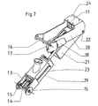
- the first housing part 19 can be inserted, as shown in the illustration FIG. 7 is apparent.
- the second housing part 20 is pivotally held at 22 on the third housing part 21, so that it is adjustable in an assembly position, the in FIG. 7 is shown.
- the first housing part 19 is completely pulled out of the third housing part 21 and can be cleaned. Subsequently, it can be pushed back into the third housing part 21 in the correct position.
- the first housing part 19 can be locked and secured in position by pivoting down the second housing part 20, wherein in this position then, as in FIG. 5 shown, the corresponding drive elements are engaged with each other.
- the second housing part 20 may be latched to the first housing part 19 and / or on the third housing part 21.
- fixing means are conceivable by means of which the position can be secured in FIG. 5 is shown.
- longitudinal guide grooves or ribs 23 may be formed on the first housing part 19 and correspondingly on the third housing part 21.
- the second housing part 20 prefferably fixed to the frame, wherein this housing part is then fastened in the region of the plate 24 to a corresponding component of the coffee machine.
- the first housing part 19 together with the housing part 21 from the position of use according to FIG. 5 in a position according to FIG. 6 be shifted, in which the first housing part 19 can then be pulled out of the third housing part 21.
- the housing part 19 can be easily removed from the entire brewing group, so that a separate cleaning of the essential components is possible.
Landscapes
- Engineering & Computer Science (AREA)
- Mechanical Engineering (AREA)
- Food Science & Technology (AREA)
- Apparatus For Making Beverages (AREA)
Abstract
Description
- Die Erfindung betrifft eine Brühgruppe für eine Kaffeemaschine, insbesondere zur Zubereitung von Espresso, mit einer Brühkammer zur Aufnahme von gemahlenem Kaffeemehl sowie mit Teilen für die Verdichtung des in der Brühkammer befindlichen Kaffeemehls, zum Auswerfen des feuchten Kaffeemehlrestes aus der Brühkammer, wobei des Weiteren Anschlüsse für die Zufuhr von Heißwasser und für den Ablauf des Filtrates vorgesehen sind.
- Im Stand der Technik sind solche Brühgruppen bekannt. Hierzu wird beispielsweise auf die
DE 20 2005 018 607 U1 verwiesen, die einen entsprechenden Getränkebereiter beschreibt. Hierbei wird die Brühkammer der Brühgruppe zum Einfüllen des Kaffees unter den Kaffeezulauf geschoben, anschließend wieder bewegt, um die Einführöffnung zu verschließen. Die Kolben bewegen sich in der Brühkammer zur Verdichtung des Kaffeemehls. Nach dem Brühen wird der Kaffeemehlrest ausgeworfen. - In der
CH 681 955 A5 - Insbesondere bei Kaffeevollautomaten wird mit solchen Einrichtungen eine Portion Kaffee nach folgendem Ablaufprinzip erstellt:
- Die Kaffeebohnen werden zu einer Portion Kaffeemehl gemahlen und das Mehl wird in eine Brühkammer der Brühgruppe geladen. Das Kaffeemehl wird in der Brühkammer der Brühgruppe verdichtet.
- Durch das verdichtete Kaffeemehl wird mit Hochdruck von beispielsweise 15 bar heißes Wasser gepumpt. Der entstehende Kaffee, also das Filtrat, läuft durch einen Auslauf in eine bereitzustellende Tasse.
- Der feuchte Kaffeemehlrest, auch Trester genannt, wird aus der Brühkammer ausgestoßen.
- Bei den bekannten Geräten wird dieses Ablaufprinzip dadurch realisiert, dass die Brühkammer der Brühgruppe bewegt wird, indem sie unter das Mahlwerk geschoben wird und Kaffeemehl eingefüllt wird. Anschließend wird die Brühkammer verschoben, damit die Einfüllöffnung verschlossen wird. Durch zwei separate Kolben, die gegenläufig in die zylindrische Brühkammer eingreifen, erfolgt eine Verdichtung des Kaffeemehls und nach dem Durchbrühen des Kaffeemehls ein Auswurf des feuchten Kaffeemehlrestes.
- Das ablaufgesteuerte Bewegen der Brühkammer und zweier Kolben erfordert eine aufwendige Mechanik und Steuerung. Darüber hinaus ist eine einfache Entnahme einer solchen Brühgruppe zum Zwecke der Reinigung überwiegend bei solchen Geräten nicht möglich.
Ausgehend von diesem Stand der Technik liegt der Erfindung die Aufgabe zugrunde, eine Brühkammer gattungsgemäßer Art zu schaffen, die nur wenige bewegte Teile aufweist, daher günstig herzustellen ist, und einen störungsfreien Betrieb über lange Zeit ermöglicht. - Zur Lösung dieser Aufgabe schlägt die Erfindung vor, dass die Brühkammer durch einen stationären unbeweglich angeordneten Zylinder gebildet ist, der seitlich nahe seines ersten Endes eine Befüllöffnung für Kaffeemehl aufweist, dass als Teil für die Verdichtung des in die Brühkammer eingefüllten Kaffeemehls am ersten Ende des Zylinders ein mittels eines ersten Stellantriebes axial verstellbarer Kolben vorgesehen ist, der in der Befüllstellung die Befüllöffnung freilässt und in der Brühstellung mit seinem Mantel die Befüllöffnung mindestens teilweise verschließt, dass am zweiten Ende des Zylinders eine Verschlussplatte mit zweitem Stellantrieb vorgesehen ist, die in der Befüllstellung und in der Brühstellung das zweite Ende des Zylinders verschließt und in der Auswurfstellung das zweite Ende des Zylinders freigibt, wobei der Kolben in der Auswurfstellung bei in Freigabelage verstellter Verschlussplatte mittels des ersten Stellantriebes in eine Auswurfstellung in Richtung zum zweiten Ende des Zylinders verstellbar ist, wobei der Kolben und die Verschlussplatte nach dem Auswerfen des feuchten Kaffeemehlrestes in die Ausgangsstellung zurück verstellbar sind, und wobei die Anschlüsse für Heißwasserzufuhr und Filtratablauf am Kolben und an der Verschlussplatte vorgesehen sind.
- Gemäß dieser Ausbildung ist die Brühkammer der Brühgruppe nicht beweglich, sondern starr angeordnet und mit einer seitlichen Befüllöffnung versehen. Des Weiteren ist lediglich ein beweglicher Kolben vorgesehen, der sowohl die Verdichtung des in der Brühkammer befindlichen Kaffeemehls übernimmt als auch den Auswurf des feuchten Kaffeemehlrestes. Zudem ist lediglich noch eine Verschlussplatte vorgesehen, die an der dem Kolben gegenüberliegenden Endseite der Brühkammer angebracht ist. Diese Verschlussplatte kann beispielsweise durch eine Schwenkbewegung in die Brühlage verstellt werden, in der das entsprechende Ende des Zylinders verschlossen ist oder aber in eine Auswurflage, in der das Ende des Zylinders freigegeben ist, so dass durch den Kolben der feuchte Kaffeemehlrest aus dem Zylinder herausgedrückt werden kann. Die entsprechende Brühgruppe weist im Vergleich zu bekannten Ausbildungen nur wenige bewegte Teile auf. Dies erlaubt nicht nur eine kostengünstige Herstellung und einen störungsfreien Betrieb, sondern die Bewegungssteuerung ist auch gegenüber den herkömmlichen Ausbildungsformen erheblich vereinfacht. Die Anschlüsse für die Heißwasserzufuhr können entweder am Kolben oder an der Verschlussplatte vorgesehen sein. Ebenso sind die Anschlüsse für den Filtratablauf entweder an der Verschlussplatte oder am Kolben vorgesehen, so dass in jedem Falle eine Durchströmung des in der zwischen Kolben und Verschlussplatte gebildeten Kammer ermöglicht ist.
- Bei dieser Anordnung werden auch kurze Wasserführungswege erreicht, so dass das heiß zugeführte Wasser beim Brühvorgang kaum abkühlt. Die Anordnung der feststehenden Brühkammer mit der Befüllöffnung ermöglicht es auch, direkt an der Befüllöffnung ein Mahlwerk zum Mahlen von Kaffee anzuordnen. Wegen der unbeweglichen Anordnung der Brühkammer ist ein Anschluss eines Mahlwerkes problemlos durchzuführen.
- Besonders bevorzugt ist dabei vorgesehen, dass der Kolben mit einer Kolbenstange versehen ist, die als Zahnstange oder Gewindespindel ausgebildet ist, und an gestellfesten Teilen der Brühgruppe ein erster elektrischer Antriebsmotor angeordnet ist, der über ein Ritzel oder eine Spindelmutter mit der Zahnstange beziehungsweise Gewindespindel verbunden ist.
- Durch diese Ausbildung wird ein sehr einfacher Antrieb für den Kolben vorgesehen, der störungsfrei ist, wobei durch einen Zahnstangenantrieb oder einen Spindelantrieb eine exakte Einstellung der Kolbenwege in einfacher Weise zu realisieren ist.
- Ferner ist bevorzugt vorgesehen, dass die Verschlussplatte an einem Stellhebel angelenkt ist, der mit seinem freien Ende exzentrisch an einer mittels des zweiten Stellantriebes drehbaren ersten Welle angeordnet ist, so dass die Verschlussplatte axial zum Zylinder verstellbar und in der Öffnungslage begrenzt schwenkbar ist.
- Durch diese Anordnung ist es möglich, die Verschlussplatte nicht nur in die Gebrauchslage und in die Freigabelage zu verschwenken, sondern beim Verschwenken der Verschlussplatte aus der Freigabestellung in die Gebrauchsstellung wird zusätzlich noch der Schwenkbewegung eine axiale Stellbewegung der Verschlussplatte überlagert, so dass diese den Zylinder dicht abschließen kann und ein unerwünschtes Austreten von Kaffeemehl und/oder Flüssigkeit behindert ist.
- Vorzugsweise weist dazu die Verschlussplatte noch eine umlaufende oder stirnseitig vorgesehene Dichtung auf, die in der Öffnungsstellung der Verschlussplatte zugänglich ist, um diese gegebenenfalls reinigen zu können.
- Des Weiteren ist bevorzugt vorgesehen, dass die drehbare erste Welle an Gehäuseteilen gelagert ist und an ihren Endbereichen Zahnräder trägt, die mit einer gezahnten zweiten Welle kämmen, die parallel zur ersten Welle gehalten ist und mittels des zweiten Stellantriebes über ein Zahnrad sowie eine Schnecke mit einem zweiten elektrischen Antriebsmotor gekoppelt ist.
- Hierdurch wird ein einfacher und kostengünstiger Antrieb zur Verfügung gestellt, mittels dessen die Verschlussplatte bewegbar und betätigbar ist, wobei durch die entsprechende Anordnung eine achsgerechte Verstellung der Verschlussplatte relativ zum Zylinder einfach zu realisieren ist.
- Zusätzlich kann vorgesehen sein, dass an der Verschlussplatte eine Wischlippe angeordnet ist.
- Vorzugsweise kann eine solche Wischlippe an der Randkante der Verschlussplatte vorgesehen sein, die in der Öffnungsstellung gesehen vorn liegt, so dass beim Schließen der Verschlussplatte die Mündung des Zylinders beziehungsweise die bis zur Mündung des Zylinders vorgeschobene Kolbenfläche durch die Wischlippe von anhaftenden Resten befreit werden kann, bevor die Verschlussplatte dann ihre Gebrauchslage einnimmt, in der der Kolben in die Ausgangslage zurückgezogen ist.
- Eine besonders vorteilhafte Weiterbildung, die auch als selbstständig erfinderisch angesehen wird, wird darin gesehen, dass die Brühgruppe ein erstes Gehäuseteil aufweist, welches den Zylinder, den Kolben samt Kolbenstange, die Befüllöffnung gegebenenfalls mit Befülltrichter, die Verschlussklappe gegebenenfalls samt Stellhebel, erster Welle und Zahnrädern aufnimmt oder hält, ein zweites Gehäuseteil, das bügelartig ausgebildet ist und den ersten Antriebsmotor, den zweiten Antriebsmotor und gegebenenfalls die zweite Welle samt Zahnrad und Schnecke trägt, sowie ein drittes Gehäuseteil, in welches das erste Gehäuseteil einschiebbar montiert ist und an dem das zweite Gehäuseteil schwenkbar gehalten ist, so dass es in eine Montagelage verstellbar ist, in der das erste Gehäuseteil aus dem dritten Gehäuseteil herausziehbar beziehungsweise in dieses einschiebbar ist, und in eine Gebrauchslage in der das in das dritte Gehäuseteil eingeschobene erste Gehäuseteil durch das zweite Gehäuseteil arretiert ist und die Antriebsmotoren mit den zu betätigenden Antriebselementen wirk verbunden sind.
- Diese Anordnung ermöglicht es, das erste Gehäuseteil mit sämtlichen Bestandteilen aus der Brühgruppe zu entnehmen, um es in einfacher Weise reinigen zu können. Sämtliche Bestandteile, die möglicherweise einer Reinigung bedürfen, sind Bestandteil des ersten Gehäuseteiles. Das dritte Gehäuseteil dient zur Aufnahme des ersten Gehäuseteiles und zur Lagerung des schwenkbeweglichen zweiten Gehäuseteiles, welches die Antriebsmotoren als wesentliche Elemente beinhaltet. Durch diese Anordnung ist nicht nur eine einfache Entnahme des ersten Gehäuseteiles samt Funktionsteilen ermöglicht, sondern auch die Herstellung und der Zusammenbau der gesamten Brühgruppe ist hierdurch vereinfacht.
- Vorzugsweise ist dabei vorgesehen, dass das zweite Gehäuseteil in der Gebrauchslage an dem ersten Gehäuseteil und/oder dem dritten Gehäuseteil verrastet ist.
- Zudem kann bevorzugt vorgesehen sein, dass das erste und das dritte Gehäuseteil Längsführungsnuten oder -rippen aufweisen, die in Gebrauchslage ineinander greifen.
- Ein Ausführungsbeispiel der Erfindung ist in der Zeichnung dargestellt und im Folgenden näher beschrieben. Es zeigt:
- Figur 1
- eine erfindungsgemäße Brühgruppe im Mittellängsschnitt gesehen;
- Figur 2
- die Brühgruppe nach dem Befüllen mit Kaffeemehl;
- Figur 3
- die Brühgruppe nach dem Verdichten des Kaffeemehls in der Brühstellung;
- Figur 4
- die Brühgruppe nach dem Brühvorgang beim Ausschieben des Tresters;
- Figur 5
- die komplette Brühgruppe in Schrägansicht von schräg vorn gesehen;
- Figur 6
- die Brühgruppe in einer Zwischenstellung mit dem in Montagelage geschwenktem zweiten Gehäuseteil;
- Figur 7
- die Brühgruppe mit hochgeschwenktem zweiten Gehäuseteil und aus dem dritten Gehäuseteil herausgezogenem ersten Gehäuseteil.
- Die in den Figuren dargestellte Brühgruppe dient zur Zubereitung von Kaffee in einer Kaffeemaschine. Die in diesem Zusammenhang nicht interessierenden Bestandteile der Kaffeemaschine sind in der Zeichnung nicht gezeigt.
- Die Brühgruppe weist eine Brühkammer 1 zur Aufnahme von gemahlenem Kaffeemehl 2 auf sowie Teile für die Verdichtung des in der Brühkammer 1 befindlichen Kaffeemehls und zum Auswerfen des feuchten Kaffeemehlrestes 3 aus der Brühkammer 1. In der Zeichnung nicht gezeigt sind Anschlüsse für die Zufuhr von Heißwasser und für den Ablauf des Filtrates.
- Die Brühkammer 1 ist durch einen stationären unbeweglich angeordneten Zylinder 4 gebildet.
- Dieser weist seitlich nahe seines in der Zeichnung oberen, ersten Endes eine Befüllöffnung 5 für Kaffeemehl auf, wobei im Ausführungsbeispiel an die Befüllöffnung 5 noch ein Einfülltrichter 6 für Kaffeemehl angeschlossen ist. Hierdurch kann unmittelbar Kaffeemehl eingegeben werden. Es ist auch möglich, über den Befülltrichter 6 ein Mahlwerk für Kaffee anzuordnen, so dass portionsweise Kaffee gemahlen und über den Befülltrichter 6 zugeführt werden kann.
- Als Teil für die Verdichtung des in die Brühkammer 1 eingefüllten Kaffeemehls 2 ist am oberen, ersten Ende des Zylinders 4 ein mittels eines ersten Stellantriebes axial verstellbarer Kolben 7 mit umlaufender Dichtlippe vorgesehen. Wie aus
Figur 1 und 2 ersichtlich, lässt der Kolben 7 in der Befüllstellung die Befüllöffnung 5 frei. In der Brühstellung, die beispielsweise inFigur 3 gezeigt ist, verschließt der Kolben 7 mit seinem Mantel 8 die Befüllöffnung 5 mindestens teilweise. Je nach Ausbildung und Anordnung kann die Befüllöffnung 5 auch hinter dem Kolben 7 freiliegen. In jedem Falle ist in der Brühstellung der Kompressionsraum zwischen Kolben 7 und einer Verschlussplatte 9 gegenüber der Befüllöffnung 5 abgeschlossen. - Am zweiten Ende des Zylinders 4 ist eine Verschlussplatte 9 vorgesehen, die mittels eines zweiten Stellantriebes betätigbar ist. Wie in
Figur 1 bis 3 ersichtlich, verschließt diese Verschlussplatte in der Befüllstellung und in der Brühstellung das zweite, untere Ende des Zylinders 4, während sie in der Auswurfstellung gemäßFigur 4 das untere Ende des Zylinders 4 freigibt, so dass der Trester durch eine entsprechende weitere Vorbewegung des Kolbens 7 ausgeworfen werden kann. Der Kolben nimmt also prinzipiell vermittelt durch den Stellantrieb drei unterschiedliche Positionen ein, nämlich erstens die Position, die inFigur 1 und 2 gezeigt ist, in der der Kolben hinter der Befüllöffnung 5 zurückliegt, zweitens die Stellung gemäßFigur 3 , in der der Kolben 7 eine Verdichtungsposition jenseits der Befüllöffnung 5 einnimmt und schließlich gemäßFigur 4 eine Auswurfstellung, in der der Kolben bis zum unteren Ende des Zylinders 4 vorgeschoben ist. - Nach dem Auswerfen des Tresters 3 gemäß
Figur 4 bewegen sich sämtliche Bestandteile in die Ausgangslage zurück, die inFigur 1 und 2 gezeigt ist. - Die Anschlüsse für Heißwasserzufuhr und Filtratablauf können am Kolben 7 respektive an der Auswurfplatte 9 vorgesehen sein, so dass das Wasser entweder in Stellrichtung des Kolbens 7 zum Zwecke des Verdichtens des Kaffeemehl durchfließt oder aber in entgegen gesetzter Richtung.
- Der Kolben 7 ist mit einer Kolbenstange 10 versehen, die rückwärtig von dem Kolben 7 abragt. Diese Kolbenstange 10 ist vorzugsweise als Gewindespindel ausgebildet. An gestellfesten Teilen der Brühgruppe ist ein erster elektrischer Antriebsmotor 11 angeordnet, der über ein Ritzel 12 oder eine Spindelmutter mit der Kolbenstange 10 wirkverbunden ist, so dass bei Betätigung des Antriebsmotors 11 eine Verstellung der Kolbenstange 10 aus der Position gemäß
Figur 1 in die Position gemäßFigur 3 und schließlich in die Position gemäßFigur 4 erfolgt und bei gegensinnigem Antrieb des Stellmotors 11 eine Zurückverlagerung der Kolbenstange aus der Position gemäßFigur 4 in die Position gemäßFigur 1 erfolgt. - Die Verschlussplatte 9 ist an einem Stellhebel 13 angelenkt, der mit seinem freien Ende exzentrisch auf einer mittels des zweiten Stellantriebes drehbaren ersten Welle 14 angeordnet ist, so dass die Verschlussplatte nicht nur schwenkbar ist, sondern auch axial zum Zylinder hin und von diesem weg verstellbar ist. In der Gebrauchslage ist die Verschlussplatte 9 zum Zylinder 4 hin verstellt und greift vorzugsweise in dessen Mündung ein. Zum Auswerfen des Tresters gemäß
Figur 4 wird die Verschlussplatte 9 mittels des Exzenters von der Mündung des Zylinders 4 abgehoben und nachfolgend beispielsweise um ca. 45 ° verschwenkt, wie inFigur 4 ersichtlich, so dass durch das Vorschieben des Kolbens 7 der Trester 3 ausgeworfen werden kann. Die drehbare erste Welle 14 ist, wie beispielsweise ausFigur 6 ersichtlich, an Gehäuseteilen drehbar gelagert und trägt an ihren Endbereichen Zahnräder 15. Diese kommen in der Gebrauchslage, wie sie inFigur 5 beispielsweise gezeigt ist, mit einer gezahnten zweiten Welle 16, die parallel zur ersten Welle 14 gehalten ist und mittels des zweiten Stellantriebes über ein Zahnrad 17 und eine Schnecke mit einem zweiten elektrischen Antriebsmotor 18 gekoppelt ist. Zusätzlich kann an der Verschlussplatte 9 an der inFigur 1 bis 3 unteren Randkante eine Wischlippe angeordnet sein, die eine Reinigung der Kolbenfläche des Kolbens 7 bei der Zurückbewegung der Stellung gemäßFigur 4 in die Stellung gemäßFigur 1 bewirkt. - Als hervorragende Besonderheit weist die Brühgruppe ein erstes Gehäuseteil 19 auf, welches den Zylinder 4, den Kolben 7 samt Kolbenstange 10, die Befüllöffnung 5 gegebenenfalls nebst Befülltrichter 6, die Verschlussklappe 9 samt Stellhebel 13, erster Welle 14 und Zahnrädern 15 aufnimmt oder hält. Ein zweites Gehäuseteil 20 ist bügelartig ausgebildet und trägt den ersten Antriebsmotor 11, den zweiten Antriebsmotor 18 sowie die zweite Welle 16 samt Zahnrad 17 und nicht dargestellter Schnecke. In ein drittes Gehäuseteil 21 ist das erste Gehäuseteil 19 einschiebbar, wie aus der Darstellung gemäß
Figur 7 ersichtlich ist. Das zweite Gehäuseteil 20 ist bei 22 an dem dritten Gehäuseteil 21 schwenkbeweglich gehalten, so dass es in eine Montagelage verstellbar ist, die inFigur 7 gezeigt ist. In dieser Lage ist das erste Gehäuseteil 19 vollständig aus dem dritten Gehäuseteil 21 herausziehbar und kann gereinigt werden. Anschließend kann es wieder in das dritte Gehäuseteil 21 lagerichtig eingeschoben werden. In der eingeschobenen Lage, die inFigur 6 gezeigt ist, kann das erste Gehäuseteil 19 durch Herunterschwenken des zweiten Gehäuseteils 20 arretiert und lagegesichert werden, wobei in dieser Stellung dann, wie inFigur 5 gezeigt, die entsprechenden Antriebselemente miteinander in Eingriff sind. - Um diese Lage, die in
Figur 5 gezeigt ist, zu sichern, kann das zweite Gehäuseteil 20 an dem ersten Gehäuseteil 19 und/oder an dem dritten Gehäuseteil 21 verrastet sein. Es sind auch andere Fixierungsmittel denkbar, mittels derer die Position gesichert werden kann, die inFigur 5 gezeigt ist. Um die entsprechende Führung beim Zusammenführen der Teile 19 und 21 zu ermöglichen, können am ersten Gehäuseteil 19 und entsprechend am dritten Gehäuseteil 21 Längsführungsnuten oder - rippen 23 ausgebildet sein. - Es ist möglich, dass zweite Gehäuseteil 20 gestellfest zu haltern, wobei dieses Gehäuseteil dann im Bereich der Platte 24 an einem entsprechenden Bestandteil der Kaffeemaschine befestigt wird. Hierbei kann dann das erste Gehäuseteil 19 zusammen mit dem Gehäuseteil 21 aus der Gebrauchsstellung gemäß
Figur 5 in eine Stellung gemäßFigur 6 verlagert werden, in der das erste Gehäuseteil 19 dann aus dem dritten Gehäuseteil 21 herausgezogen werden kann. Auf diese Weise ist das Gehäuseteil 19 in einfacher Weise aus der gesamten Brühgruppe zu entnehmen, so dass eine separate Reinigung der wesentlichen Bestandteile ermöglicht ist. - Die Erfindung ist nicht auf das Ausführungsbeispiel beschränkt, sondern im Rahmen der Offenbarung vielfach variabel.
- Alle neuen, in der Beschreibung und/oder Zeichnung offenbarten Einzel- und Kombinationsmerkmale werden als erfindungswesentlich angesehen.
Claims (8)
- Brühgruppe für eine Kaffeemaschine, insbesondere zur Zubereitung von Espresso, mit einer Brühkammer (1) zur Aufnahme von gemahlenem Kaffeemehl (2) sowie mit Teilen für die Verdichtung des in der Brühkammer (1) befindlichen Kaffeemehls (2), zum Auswerfen des feuchten Kaffeemehlrestes (3) aus der Brühkammer (1), wobei des Weiteren Anschlüsse für die Zufuhr von Heißwasser und für den Ablauf des Filtrates vorgesehen sind, dadurch gekennzeichnet, dass die Brühkammer (1) durch einen stationären unbeweglich angeordneten Zylinder (4) gebildet ist, der seitlich nahe seines ersten Endes eine Befüllöffnung (5) für Kaffeemehl aufweist, dass als Teil für die Verdichtung des in die Brühkammer (1) eingefüllten Kaffeemehls am ersten Ende des Zylinders (4) ein mittels eines ersten Stellantriebes axial verstellbarer Kolben (7) vorgesehen ist, der in der Befüllstellung die Befüllöffnung (5) freilässt und in der Brühstellung mit seinem Mantel die Befüllöffnung (5) mindestens teilweise verschließt, dass am zweiten Ende des Zylinders (4) eine Verschlussplatte (9) mit zweitem Stellantrieb vorgesehen ist, die in der Befüllstellung und in der Brühstellung das zweite Ende des Zylinders (4) verschließt und in der Auswurfstellung das zweite Ende des Zylinders (4) freigibt, wobei der Kolben (7) in der Auswurfstellung bei in Freigabelage verstellter Verschlussplatte (9) mittels des ersten Stellantriebes in eine Auswurfstellung in Richtung zum zweiten Ende des Zylinders (4) verstellbar ist, wobei der Kolben (7) und die Verschlussplatte (9) nach dem Auswerfen des feuchten Kaffeemehlrestes (3) in die Ausgangsstellung zurück verstellbar sind, und wobei die Anschlüsse für Heißwasserzufuhr und Filtratablauf am Kolben (7) und an der Verschlussplatte (9) vorgesehen sind.
- Brühgruppe nach Anspruch 1, dadurch gekennzeichnet, dass der Kolben (7) mit einer Kolbenstange (10) versehen ist, die als Zahnstange oder Gewindespindel ausgebildet ist, und an gestellfesten Teilen der Brühgruppe ein erster elektrischer Antriebsmotor (11) angeordnet ist, der über ein Ritzel oder eine Spindelmutter (12) mit der Zahnstange beziehungsweise Gewindespindel (10) verbunden ist.
- Brühgruppe nach Anspruch 1 oder 2, dadurch gekennzeichnet, dass die Verschlussplatte (9) an einem Stellhebel (13) angelenkt ist, der mit seinem freien Ende exzentrisch an einer mittels des zweiten Stellantriebes drehbaren ersten Welle (14) angeordnet ist, so dass die Verschlussplatte (9) axial zum Zylinder (4) verstellbar und in der Öffnungslage begrenzt schwenkbar ist.
- Brühgruppe nach Anspruch 3, dadurch gekennzeichnet, dass die drehbare erste Welle (14) an Gehäuseteilen gelagert ist und an ihren Endbereichen Zahnräder (15) trägt, die mit einer gezahnten zweiten Welle (16) kämmen, die parallel zur ersten Welle (14) gehalten ist und mittels des zweiten Stellantriebes über ein Zahnrad (17) sowie eine Schnecke mit einem zweiten elektrischen Antriebsmotor (18) gekoppelt ist.
- Brühgruppe nach einem der Ansprüche 1 bis 4, dadurch gekennzeichnet, dass an der Verschlussplatte (9) eine Wischlippe angeordnet ist.
- Brühgruppe nach einem der Ansprüche 1 bis 5, dadurch gekennzeichnet, dass die Brühgruppe ein erstes Gehäuseteil (19) aufweist, welches den Zylinder (4), den Kolben (7) samt Kolbenstange (10), die Befüllöffnung (5) gegebenenfalls mit Befülltrichter (6), die Verschlussklappe (9) gegebenenfalls samt Stellhebel (13), erster Welle (14) und Zahnrädern (15) aufnimmt oder hält, ein zweites Gehäuseteil (20), das bügelartig ausgebildet ist und den ersten Antriebsmotor (11), den zweiten Antriebsmotor (18) und gegebenenfalls die zweite Welle (16) samt Zahnrad (17) und Schnecke trägt, sowie ein drittes Gehäuseteil (21), in welches das erste Gehäuseteil (19) einschiebbar montiert ist und an dem das zweite Gehäuseteil (20) schwenkbar gehalten ist, so dass es in eine Montagelage verstellbar ist, in der das erste Gehäuseteil (19) aus dem dritten Gehäuseteil (21) herausziehbar beziehungsweise in dieses einschiebbar ist, und in eine Gebrauchslage, in der das in das dritte Gehäuseteil (21) eingeschobene erste Gehäuseteil (19) durch das zweite Gehäuseteil (20) arretiert ist und die Antriebsmotoren (11,18) mit den zu betätigenden Antriebselementen wirkverbunden sind.
- Brühgruppe nach Anspruch 6, dadurch gekennzeichnet, dass das zweite Gehäuseteil (20) in der Gebrauchslage an dem ersten Gehäuseteil (19) und/oder dem dritten Gehäuseteil (21) verrastet ist.
- Brühgruppe nach Anspruch 6 oder 7, dadurch gekennzeichnet, dass das erste und das dritte Gehäuseteil (19,21) Längsführungsnuten oder -rippen (23) aufweisen, die in Gebrauchslage ineinander greifen.
Applications Claiming Priority (1)
| Application Number | Priority Date | Filing Date | Title |
|---|---|---|---|
| DE200710042379 DE102007042379B3 (de) | 2007-09-06 | 2007-09-06 | Brühgruppe für eine Kaffeemaschine |
Publications (3)
| Publication Number | Publication Date |
|---|---|
| EP2033550A2 true EP2033550A2 (de) | 2009-03-11 |
| EP2033550A3 EP2033550A3 (de) | 2009-12-30 |
| EP2033550B1 EP2033550B1 (de) | 2013-05-29 |
Family
ID=40076274
Family Applications (1)
| Application Number | Title | Priority Date | Filing Date |
|---|---|---|---|
| EP20080012076 Active EP2033550B1 (de) | 2007-09-06 | 2008-07-04 | Brühgruppe für eine Kaffeemaschine |
Country Status (2)
| Country | Link |
|---|---|
| EP (1) | EP2033550B1 (de) |
| DE (1) | DE102007042379B3 (de) |
Cited By (5)
| Publication number | Priority date | Publication date | Assignee | Title |
|---|---|---|---|---|
| DE102010007222A1 (de) | 2010-02-09 | 2010-08-26 | SEVERIN ELEKTROGERÄTE GmbH | Kaffeemaschine |
| DE102010008200A1 (de) | 2010-02-17 | 2010-12-02 | SEVERIN ELEKTROGERÄTE GmbH | Brühgruppe für eine Kaffemaschine |
| DE102010008201A1 (de) | 2010-02-17 | 2010-12-30 | SEVERIN ELEKTROGERÄTE GmbH | Brühgruppe für eine Kaffeemaschine |
| CN103120545A (zh) * | 2011-10-14 | 2013-05-29 | 塞维林电器有限责任公司 | 烧煮组件 |
| WO2021086297A1 (en) * | 2019-10-30 | 2021-05-06 | Arzum Elektri̇kli̇ Ev Aletleri̇ San. Ve Ti̇c. A.Ş. | A hot beverage preparing device |
Families Citing this family (2)
| Publication number | Priority date | Publication date | Assignee | Title |
|---|---|---|---|---|
| DE102009032677A1 (de) | 2009-07-09 | 2011-01-13 | Werner Balkau | Brühgruppe, insbesondere für eine Kaffeemaschine |
| DE102011008095A1 (de) * | 2011-01-07 | 2011-06-22 | Severin Elektrogeräte GmbH, 59846 | Brühgruppe für eine Kaffeemaschine |
Citations (2)
| Publication number | Priority date | Publication date | Assignee | Title |
|---|---|---|---|---|
| CH681955A5 (de) | 1991-03-28 | 1993-06-30 | Egro Ag | |
| DE202005018607U1 (de) | 2005-11-29 | 2006-02-02 | Wik Far East Ltd., North Point | Brüheinheit für eine Kaffeemaschine |
Family Cites Families (1)
| Publication number | Priority date | Publication date | Assignee | Title |
|---|---|---|---|---|
| US20050193891A1 (en) * | 2004-03-08 | 2005-09-08 | Brent Garson | Espresso making apparatus and method of brewing espresso |
-
2007
- 2007-09-06 DE DE200710042379 patent/DE102007042379B3/de active Active
-
2008
- 2008-07-04 EP EP20080012076 patent/EP2033550B1/de active Active
Patent Citations (2)
| Publication number | Priority date | Publication date | Assignee | Title |
|---|---|---|---|---|
| CH681955A5 (de) | 1991-03-28 | 1993-06-30 | Egro Ag | |
| DE202005018607U1 (de) | 2005-11-29 | 2006-02-02 | Wik Far East Ltd., North Point | Brüheinheit für eine Kaffeemaschine |
Cited By (6)
| Publication number | Priority date | Publication date | Assignee | Title |
|---|---|---|---|---|
| DE102010007222A1 (de) | 2010-02-09 | 2010-08-26 | SEVERIN ELEKTROGERÄTE GmbH | Kaffeemaschine |
| DE102010007222B4 (de) * | 2010-02-09 | 2018-04-12 | SEVERIN ELEKTROGERÄTE GmbH | Kaffeemaschine |
| DE102010008200A1 (de) | 2010-02-17 | 2010-12-02 | SEVERIN ELEKTROGERÄTE GmbH | Brühgruppe für eine Kaffemaschine |
| DE102010008201A1 (de) | 2010-02-17 | 2010-12-30 | SEVERIN ELEKTROGERÄTE GmbH | Brühgruppe für eine Kaffeemaschine |
| CN103120545A (zh) * | 2011-10-14 | 2013-05-29 | 塞维林电器有限责任公司 | 烧煮组件 |
| WO2021086297A1 (en) * | 2019-10-30 | 2021-05-06 | Arzum Elektri̇kli̇ Ev Aletleri̇ San. Ve Ti̇c. A.Ş. | A hot beverage preparing device |
Also Published As
| Publication number | Publication date |
|---|---|
| EP2033550B1 (de) | 2013-05-29 |
| DE102007042379B3 (de) | 2009-01-02 |
| EP2033550A3 (de) | 2009-12-30 |
Similar Documents
| Publication | Publication Date | Title |
|---|---|---|
| EP2033550B1 (de) | Brühgruppe für eine Kaffeemaschine | |
| EP1665968B1 (de) | Brühkopf einer Espressomaschine | |
| EP1595480B1 (de) | Kaffeemaschinenautomat | |
| EP1912542B1 (de) | Vorrichtung zum extrahieren eines in einer kapsel enthaltenen extraktionsgutes mit einem flüssigen extraktionsmittel | |
| DE3607656C2 (de) | ||
| WO2007017455A1 (de) | Vorrichtung zum extrahieren eines in einer kapsel enthaltenen extraktionsgutes mit einem flüssigen extraktionsmittel | |
| DE2158173C3 (de) | Maschine zur Zubereitung von Aufgüssen, insbesondere von Expresskaffee | |
| EP2030537B1 (de) | Brüheinrichtung für eine Kaffeemaschine | |
| DE60110600T2 (de) | Automatische kaffeemaschine mit einer bewegbaren brühkopfeinheit die ohne werkzeug abbaubar ist | |
| DE60116835T2 (de) | Abnehmbarer verteiler für kaffeemaschine | |
| WO2009034002A1 (de) | Brüheinrichtung für eine kaffeemaschine | |
| EP0641536B1 (de) | Kaffeemaschinenautomat | |
| EP2105075B1 (de) | Brüheinrichtung für eine Kaffeemaschine | |
| DE102018009992B4 (de) | Füllvorrichtung für wiederbefüllbare Kaffeekapseln und Kaffeemühle mit Füllvorrichtung | |
| WO2009040227A1 (de) | Brüheinrichtung für eine kaffeemaschine | |
| EP2422663B1 (de) | Brühgruppe für einen Getränkeautomaten | |
| EP2581002B1 (de) | Brühgruppe | |
| WO2009100552A1 (de) | Brühgruppe für eine kaffeemaschine | |
| DE19848370B4 (de) | Vorrichtung und Verfahren zur Zubereitung eines Kaffeeaufgusses | |
| EP3291714B1 (de) | Kaffeemaschine sowie betriebsverfahren | |
| DE102007009355B4 (de) | Brüheinheit in einem Heißgetränkeautomaten | |
| EP2036467B1 (de) | Perkolator zur Zubereitung von Brühgetränken | |
| EP2764803B1 (de) | Kaffeevollautomat mit Spindelbrüheinheit |
Legal Events
| Date | Code | Title | Description |
|---|---|---|---|
| PUAI | Public reference made under article 153(3) epc to a published international application that has entered the european phase |
Free format text: ORIGINAL CODE: 0009012 |
|
| AK | Designated contracting states |
Kind code of ref document: A2 Designated state(s): AT BE BG CH CY CZ DE DK EE ES FI FR GB GR HR HU IE IS IT LI LT LU LV MC MT NL NO PL PT RO SE SI SK TR |
|
| AX | Request for extension of the european patent |
Extension state: AL BA MK RS |
|
| PUAL | Search report despatched |
Free format text: ORIGINAL CODE: 0009013 |
|
| AK | Designated contracting states |
Kind code of ref document: A3 Designated state(s): AT BE BG CH CY CZ DE DK EE ES FI FR GB GR HR HU IE IS IT LI LT LU LV MC MT NL NO PL PT RO SE SI SK TR |
|
| AX | Request for extension of the european patent |
Extension state: AL BA MK RS |
|
| 17P | Request for examination filed |
Effective date: 20100202 |
|
| AKX | Designation fees paid |
Designated state(s): AT BE BG CH CY CZ DE DK EE ES FI FR GB GR HR HU IE IS IT LI LT LU LV MC MT NL NO PL PT RO SE SI SK TR |
|
| AXX | Extension fees paid |
Extension state: AL Payment date: 20100202 Extension state: MK Payment date: 20100202 Extension state: BA Payment date: 20100202 Extension state: RS Payment date: 20100202 |
|
| GRAP | Despatch of communication of intention to grant a patent |
Free format text: ORIGINAL CODE: EPIDOSNIGR1 |
|
| GRAS | Grant fee paid |
Free format text: ORIGINAL CODE: EPIDOSNIGR3 |
|
| GRAA | (expected) grant |
Free format text: ORIGINAL CODE: 0009210 |
|
| AK | Designated contracting states |
Kind code of ref document: B1 Designated state(s): AT BE BG CH CY CZ DE DK EE ES FI FR GB GR HR HU IE IS IT LI LT LU LV MC MT NL NO PL PT RO SE SI SK TR |
|
| AX | Request for extension of the european patent |
Extension state: AL BA MK RS |
|
| REG | Reference to a national code |
Ref country code: GB Ref legal event code: FG4D Free format text: NOT ENGLISH |
|
| REG | Reference to a national code |
Ref country code: CH Ref legal event code: EP Ref country code: CH Ref legal event code: NV Representative=s name: TROESCH SCHEIDEGGER WERNER AG, CH |
|
| REG | Reference to a national code |
Ref country code: AT Ref legal event code: REF Ref document number: 613840 Country of ref document: AT Kind code of ref document: T Effective date: 20130615 |
|
| REG | Reference to a national code |
Ref country code: IE Ref legal event code: FG4D Free format text: LANGUAGE OF EP DOCUMENT: GERMAN |
|
| REG | Reference to a national code |
Ref country code: DE Ref legal event code: R096 Ref document number: 502008010015 Country of ref document: DE Effective date: 20130725 |
|
| REG | Reference to a national code |
Ref country code: LT Ref legal event code: MG4D |
|
| PG25 | Lapsed in a contracting state [announced via postgrant information from national office to epo] |
Ref country code: SE Free format text: LAPSE BECAUSE OF FAILURE TO SUBMIT A TRANSLATION OF THE DESCRIPTION OR TO PAY THE FEE WITHIN THE PRESCRIBED TIME-LIMIT Effective date: 20130529 Ref country code: SI Free format text: LAPSE BECAUSE OF FAILURE TO SUBMIT A TRANSLATION OF THE DESCRIPTION OR TO PAY THE FEE WITHIN THE PRESCRIBED TIME-LIMIT Effective date: 20130529 Ref country code: FI Free format text: LAPSE BECAUSE OF FAILURE TO SUBMIT A TRANSLATION OF THE DESCRIPTION OR TO PAY THE FEE WITHIN THE PRESCRIBED TIME-LIMIT Effective date: 20130529 Ref country code: LT Free format text: LAPSE BECAUSE OF FAILURE TO SUBMIT A TRANSLATION OF THE DESCRIPTION OR TO PAY THE FEE WITHIN THE PRESCRIBED TIME-LIMIT Effective date: 20130529 Ref country code: GR Free format text: LAPSE BECAUSE OF FAILURE TO SUBMIT A TRANSLATION OF THE DESCRIPTION OR TO PAY THE FEE WITHIN THE PRESCRIBED TIME-LIMIT Effective date: 20130830 Ref country code: PT Free format text: LAPSE BECAUSE OF FAILURE TO SUBMIT A TRANSLATION OF THE DESCRIPTION OR TO PAY THE FEE WITHIN THE PRESCRIBED TIME-LIMIT Effective date: 20130930 Ref country code: ES Free format text: LAPSE BECAUSE OF FAILURE TO SUBMIT A TRANSLATION OF THE DESCRIPTION OR TO PAY THE FEE WITHIN THE PRESCRIBED TIME-LIMIT Effective date: 20130909 Ref country code: NO Free format text: LAPSE BECAUSE OF FAILURE TO SUBMIT A TRANSLATION OF THE DESCRIPTION OR TO PAY THE FEE WITHIN THE PRESCRIBED TIME-LIMIT Effective date: 20130829 Ref country code: IS Free format text: LAPSE BECAUSE OF FAILURE TO SUBMIT A TRANSLATION OF THE DESCRIPTION OR TO PAY THE FEE WITHIN THE PRESCRIBED TIME-LIMIT Effective date: 20130929 |
|
| REG | Reference to a national code |
Ref country code: NL Ref legal event code: VDEP Effective date: 20130529 |
|
| PG25 | Lapsed in a contracting state [announced via postgrant information from national office to epo] |
Ref country code: PL Free format text: LAPSE BECAUSE OF FAILURE TO SUBMIT A TRANSLATION OF THE DESCRIPTION OR TO PAY THE FEE WITHIN THE PRESCRIBED TIME-LIMIT Effective date: 20130529 Ref country code: HR Free format text: LAPSE BECAUSE OF FAILURE TO SUBMIT A TRANSLATION OF THE DESCRIPTION OR TO PAY THE FEE WITHIN THE PRESCRIBED TIME-LIMIT Effective date: 20130529 Ref country code: BG Free format text: LAPSE BECAUSE OF FAILURE TO SUBMIT A TRANSLATION OF THE DESCRIPTION OR TO PAY THE FEE WITHIN THE PRESCRIBED TIME-LIMIT Effective date: 20130829 |
|
| PG25 | Lapsed in a contracting state [announced via postgrant information from national office to epo] |
Ref country code: LV Free format text: LAPSE BECAUSE OF FAILURE TO SUBMIT A TRANSLATION OF THE DESCRIPTION OR TO PAY THE FEE WITHIN THE PRESCRIBED TIME-LIMIT Effective date: 20130529 |
|
| BERE | Be: lapsed |
Owner name: SEVERIN ELEKTROGERATE G.M.B.H. Effective date: 20130731 |
|
| PG25 | Lapsed in a contracting state [announced via postgrant information from national office to epo] |
Ref country code: DK Free format text: LAPSE BECAUSE OF FAILURE TO SUBMIT A TRANSLATION OF THE DESCRIPTION OR TO PAY THE FEE WITHIN THE PRESCRIBED TIME-LIMIT Effective date: 20130529 Ref country code: EE Free format text: LAPSE BECAUSE OF FAILURE TO SUBMIT A TRANSLATION OF THE DESCRIPTION OR TO PAY THE FEE WITHIN THE PRESCRIBED TIME-LIMIT Effective date: 20130529 Ref country code: CZ Free format text: LAPSE BECAUSE OF FAILURE TO SUBMIT A TRANSLATION OF THE DESCRIPTION OR TO PAY THE FEE WITHIN THE PRESCRIBED TIME-LIMIT Effective date: 20130529 Ref country code: SK Free format text: LAPSE BECAUSE OF FAILURE TO SUBMIT A TRANSLATION OF THE DESCRIPTION OR TO PAY THE FEE WITHIN THE PRESCRIBED TIME-LIMIT Effective date: 20130529 |
|
| PG25 | Lapsed in a contracting state [announced via postgrant information from national office to epo] |
Ref country code: RO Free format text: LAPSE BECAUSE OF FAILURE TO SUBMIT A TRANSLATION OF THE DESCRIPTION OR TO PAY THE FEE WITHIN THE PRESCRIBED TIME-LIMIT Effective date: 20130529 Ref country code: NL Free format text: LAPSE BECAUSE OF FAILURE TO SUBMIT A TRANSLATION OF THE DESCRIPTION OR TO PAY THE FEE WITHIN THE PRESCRIBED TIME-LIMIT Effective date: 20130529 Ref country code: MC Free format text: LAPSE BECAUSE OF FAILURE TO SUBMIT A TRANSLATION OF THE DESCRIPTION OR TO PAY THE FEE WITHIN THE PRESCRIBED TIME-LIMIT Effective date: 20130529 |
|
| PLBE | No opposition filed within time limit |
Free format text: ORIGINAL CODE: 0009261 |
|
| STAA | Information on the status of an ep patent application or granted ep patent |
Free format text: STATUS: NO OPPOSITION FILED WITHIN TIME LIMIT |
|
| REG | Reference to a national code |
Ref country code: IE Ref legal event code: MM4A |
|
| PG25 | Lapsed in a contracting state [announced via postgrant information from national office to epo] |
Ref country code: BE Free format text: LAPSE BECAUSE OF NON-PAYMENT OF DUE FEES Effective date: 20130731 |
|
| 26N | No opposition filed |
Effective date: 20140303 |
|
| REG | Reference to a national code |
Ref country code: DE Ref legal event code: R097 Ref document number: 502008010015 Country of ref document: DE Effective date: 20140303 |
|
| PG25 | Lapsed in a contracting state [announced via postgrant information from national office to epo] |
Ref country code: IE Free format text: LAPSE BECAUSE OF NON-PAYMENT OF DUE FEES Effective date: 20130704 |
|
| PG25 | Lapsed in a contracting state [announced via postgrant information from national office to epo] |
Ref country code: CY Free format text: LAPSE BECAUSE OF FAILURE TO SUBMIT A TRANSLATION OF THE DESCRIPTION OR TO PAY THE FEE WITHIN THE PRESCRIBED TIME-LIMIT Effective date: 20130529 Ref country code: TR Free format text: LAPSE BECAUSE OF FAILURE TO SUBMIT A TRANSLATION OF THE DESCRIPTION OR TO PAY THE FEE WITHIN THE PRESCRIBED TIME-LIMIT Effective date: 20130529 Ref country code: MT Free format text: LAPSE BECAUSE OF FAILURE TO SUBMIT A TRANSLATION OF THE DESCRIPTION OR TO PAY THE FEE WITHIN THE PRESCRIBED TIME-LIMIT Effective date: 20130529 |
|
| PG25 | Lapsed in a contracting state [announced via postgrant information from national office to epo] |
Ref country code: HU Free format text: LAPSE BECAUSE OF FAILURE TO SUBMIT A TRANSLATION OF THE DESCRIPTION OR TO PAY THE FEE WITHIN THE PRESCRIBED TIME-LIMIT; INVALID AB INITIO Effective date: 20080704 Ref country code: LU Free format text: LAPSE BECAUSE OF NON-PAYMENT OF DUE FEES Effective date: 20130704 |
|
| REG | Reference to a national code |
Ref country code: FR Ref legal event code: PLFP Year of fee payment: 9 |
|
| REG | Reference to a national code |
Ref country code: FR Ref legal event code: PLFP Year of fee payment: 10 |
|
| REG | Reference to a national code |
Ref country code: FR Ref legal event code: PLFP Year of fee payment: 11 |
|
| P01 | Opt-out of the competence of the unified patent court (upc) registered |
Effective date: 20230509 |
|
| PGFP | Annual fee paid to national office [announced via postgrant information from national office to epo] |
Ref country code: IT Payment date: 20230727 Year of fee payment: 16 Ref country code: GB Payment date: 20230728 Year of fee payment: 16 Ref country code: CH Payment date: 20230804 Year of fee payment: 16 Ref country code: AT Payment date: 20230721 Year of fee payment: 16 |
|
| PGFP | Annual fee paid to national office [announced via postgrant information from national office to epo] |
Ref country code: FR Payment date: 20230724 Year of fee payment: 16 |
|
| PGFP | Annual fee paid to national office [announced via postgrant information from national office to epo] |
Ref country code: DE Payment date: 20231004 Year of fee payment: 16 |