EP2032090B1 - Système de distribution de stent à branches - Google Patents
Système de distribution de stent à branches Download PDFInfo
- Publication number
- EP2032090B1 EP2032090B1 EP07796274.4A EP07796274A EP2032090B1 EP 2032090 B1 EP2032090 B1 EP 2032090B1 EP 07796274 A EP07796274 A EP 07796274A EP 2032090 B1 EP2032090 B1 EP 2032090B1
- Authority
- EP
- European Patent Office
- Prior art keywords
- catheter
- delivery system
- side branch
- interventional delivery
- guidewire
- Prior art date
- Legal status (The legal status is an assumption and is not a legal conclusion. Google has not performed a legal analysis and makes no representation as to the accuracy of the status listed.)
- Active
Links
- 230000002792 vascular Effects 0.000 claims description 3
- 210000005166 vasculature Anatomy 0.000 description 14
- 238000000034 method Methods 0.000 description 7
- 238000007789 sealing Methods 0.000 description 6
- 206010002329 Aneurysm Diseases 0.000 description 4
- 210000001367 artery Anatomy 0.000 description 4
- 230000000712 assembly Effects 0.000 description 4
- 238000000429 assembly Methods 0.000 description 4
- -1 polyethylenes Polymers 0.000 description 4
- 230000010412 perfusion Effects 0.000 description 3
- 238000000926 separation method Methods 0.000 description 3
- 238000001356 surgical procedure Methods 0.000 description 3
- XDTMQSROBMDMFD-UHFFFAOYSA-N C1CCCCC1 Chemical compound C1CCCCC1 XDTMQSROBMDMFD-UHFFFAOYSA-N 0.000 description 2
- 230000001154 acute effect Effects 0.000 description 2
- 238000004873 anchoring Methods 0.000 description 2
- 230000007423 decrease Effects 0.000 description 2
- 208000014674 injury Diseases 0.000 description 2
- 230000002093 peripheral effect Effects 0.000 description 2
- 230000008733 trauma Effects 0.000 description 2
- 240000007817 Olea europaea Species 0.000 description 1
- 208000031481 Pathologic Constriction Diseases 0.000 description 1
- 239000004698 Polyethylene Substances 0.000 description 1
- 239000004743 Polypropylene Substances 0.000 description 1
- 230000002965 anti-thrombogenic effect Effects 0.000 description 1
- 210000000709 aorta Anatomy 0.000 description 1
- 210000000941 bile Anatomy 0.000 description 1
- 239000000560 biocompatible material Substances 0.000 description 1
- 210000004204 blood vessel Anatomy 0.000 description 1
- 210000000621 bronchi Anatomy 0.000 description 1
- 238000000576 coating method Methods 0.000 description 1
- 239000003814 drug Substances 0.000 description 1
- 229940079593 drug Drugs 0.000 description 1
- 230000002349 favourable effect Effects 0.000 description 1
- 210000001105 femoral artery Anatomy 0.000 description 1
- 239000012530 fluid Substances 0.000 description 1
- 230000002496 gastric effect Effects 0.000 description 1
- 238000002513 implantation Methods 0.000 description 1
- 238000010348 incorporation Methods 0.000 description 1
- 238000003780 insertion Methods 0.000 description 1
- 230000037431 insertion Effects 0.000 description 1
- 239000000463 material Substances 0.000 description 1
- 230000007246 mechanism Effects 0.000 description 1
- 238000012986 modification Methods 0.000 description 1
- 230000004048 modification Effects 0.000 description 1
- 238000003032 molecular docking Methods 0.000 description 1
- 229920001778 nylon Polymers 0.000 description 1
- 210000000056 organ Anatomy 0.000 description 1
- 229920000515 polycarbonate Polymers 0.000 description 1
- 239000004417 polycarbonate Substances 0.000 description 1
- 229920000573 polyethylene Polymers 0.000 description 1
- 229920001155 polypropylene Polymers 0.000 description 1
- 229920001296 polysiloxane Polymers 0.000 description 1
- 229920001343 polytetrafluoroethylene Polymers 0.000 description 1
- 229920002635 polyurethane Polymers 0.000 description 1
- 239000004814 polyurethane Substances 0.000 description 1
- 229920000915 polyvinyl chloride Polymers 0.000 description 1
- 210000002307 prostate Anatomy 0.000 description 1
- 230000000241 respiratory effect Effects 0.000 description 1
- 229910001220 stainless steel Inorganic materials 0.000 description 1
- 230000036262 stenosis Effects 0.000 description 1
- 208000037804 stenosis Diseases 0.000 description 1
- 210000003270 subclavian artery Anatomy 0.000 description 1
- 230000000472 traumatic effect Effects 0.000 description 1
- 210000003708 urethra Anatomy 0.000 description 1
- 238000012800 visualization Methods 0.000 description 1
Images


Classifications
-
- A—HUMAN NECESSITIES
- A61—MEDICAL OR VETERINARY SCIENCE; HYGIENE
- A61F—FILTERS IMPLANTABLE INTO BLOOD VESSELS; PROSTHESES; DEVICES PROVIDING PATENCY TO, OR PREVENTING COLLAPSING OF, TUBULAR STRUCTURES OF THE BODY, e.g. STENTS; ORTHOPAEDIC, NURSING OR CONTRACEPTIVE DEVICES; FOMENTATION; TREATMENT OR PROTECTION OF EYES OR EARS; BANDAGES, DRESSINGS OR ABSORBENT PADS; FIRST-AID KITS
- A61F2/00—Filters implantable into blood vessels; Prostheses, i.e. artificial substitutes or replacements for parts of the body; Appliances for connecting them with the body; Devices providing patency to, or preventing collapsing of, tubular structures of the body, e.g. stents
- A61F2/95—Instruments specially adapted for placement or removal of stents or stent-grafts
- A61F2/954—Instruments specially adapted for placement or removal of stents or stent-grafts for placing stents or stent-grafts in a bifurcation
-
- A—HUMAN NECESSITIES
- A61—MEDICAL OR VETERINARY SCIENCE; HYGIENE
- A61F—FILTERS IMPLANTABLE INTO BLOOD VESSELS; PROSTHESES; DEVICES PROVIDING PATENCY TO, OR PREVENTING COLLAPSING OF, TUBULAR STRUCTURES OF THE BODY, e.g. STENTS; ORTHOPAEDIC, NURSING OR CONTRACEPTIVE DEVICES; FOMENTATION; TREATMENT OR PROTECTION OF EYES OR EARS; BANDAGES, DRESSINGS OR ABSORBENT PADS; FIRST-AID KITS
- A61F2/00—Filters implantable into blood vessels; Prostheses, i.e. artificial substitutes or replacements for parts of the body; Appliances for connecting them with the body; Devices providing patency to, or preventing collapsing of, tubular structures of the body, e.g. stents
- A61F2/02—Prostheses implantable into the body
- A61F2/04—Hollow or tubular parts of organs, e.g. bladders, tracheae, bronchi or bile ducts
- A61F2/06—Blood vessels
- A61F2/07—Stent-grafts
-
- A—HUMAN NECESSITIES
- A61—MEDICAL OR VETERINARY SCIENCE; HYGIENE
- A61F—FILTERS IMPLANTABLE INTO BLOOD VESSELS; PROSTHESES; DEVICES PROVIDING PATENCY TO, OR PREVENTING COLLAPSING OF, TUBULAR STRUCTURES OF THE BODY, e.g. STENTS; ORTHOPAEDIC, NURSING OR CONTRACEPTIVE DEVICES; FOMENTATION; TREATMENT OR PROTECTION OF EYES OR EARS; BANDAGES, DRESSINGS OR ABSORBENT PADS; FIRST-AID KITS
- A61F2/00—Filters implantable into blood vessels; Prostheses, i.e. artificial substitutes or replacements for parts of the body; Appliances for connecting them with the body; Devices providing patency to, or preventing collapsing of, tubular structures of the body, e.g. stents
- A61F2/82—Devices providing patency to, or preventing collapsing of, tubular structures of the body, e.g. stents
- A61F2/856—Single tubular stent with a side portal passage
-
- A—HUMAN NECESSITIES
- A61—MEDICAL OR VETERINARY SCIENCE; HYGIENE
- A61F—FILTERS IMPLANTABLE INTO BLOOD VESSELS; PROSTHESES; DEVICES PROVIDING PATENCY TO, OR PREVENTING COLLAPSING OF, TUBULAR STRUCTURES OF THE BODY, e.g. STENTS; ORTHOPAEDIC, NURSING OR CONTRACEPTIVE DEVICES; FOMENTATION; TREATMENT OR PROTECTION OF EYES OR EARS; BANDAGES, DRESSINGS OR ABSORBENT PADS; FIRST-AID KITS
- A61F2/00—Filters implantable into blood vessels; Prostheses, i.e. artificial substitutes or replacements for parts of the body; Appliances for connecting them with the body; Devices providing patency to, or preventing collapsing of, tubular structures of the body, e.g. stents
- A61F2/02—Prostheses implantable into the body
- A61F2/04—Hollow or tubular parts of organs, e.g. bladders, tracheae, bronchi or bile ducts
- A61F2/06—Blood vessels
- A61F2002/061—Blood vessels provided with means for allowing access to secondary lumens
-
- A—HUMAN NECESSITIES
- A61—MEDICAL OR VETERINARY SCIENCE; HYGIENE
- A61F—FILTERS IMPLANTABLE INTO BLOOD VESSELS; PROSTHESES; DEVICES PROVIDING PATENCY TO, OR PREVENTING COLLAPSING OF, TUBULAR STRUCTURES OF THE BODY, e.g. STENTS; ORTHOPAEDIC, NURSING OR CONTRACEPTIVE DEVICES; FOMENTATION; TREATMENT OR PROTECTION OF EYES OR EARS; BANDAGES, DRESSINGS OR ABSORBENT PADS; FIRST-AID KITS
- A61F2/00—Filters implantable into blood vessels; Prostheses, i.e. artificial substitutes or replacements for parts of the body; Appliances for connecting them with the body; Devices providing patency to, or preventing collapsing of, tubular structures of the body, e.g. stents
- A61F2/02—Prostheses implantable into the body
- A61F2/04—Hollow or tubular parts of organs, e.g. bladders, tracheae, bronchi or bile ducts
- A61F2/06—Blood vessels
- A61F2002/065—Y-shaped blood vessels
-
- A—HUMAN NECESSITIES
- A61—MEDICAL OR VETERINARY SCIENCE; HYGIENE
- A61F—FILTERS IMPLANTABLE INTO BLOOD VESSELS; PROSTHESES; DEVICES PROVIDING PATENCY TO, OR PREVENTING COLLAPSING OF, TUBULAR STRUCTURES OF THE BODY, e.g. STENTS; ORTHOPAEDIC, NURSING OR CONTRACEPTIVE DEVICES; FOMENTATION; TREATMENT OR PROTECTION OF EYES OR EARS; BANDAGES, DRESSINGS OR ABSORBENT PADS; FIRST-AID KITS
- A61F2/00—Filters implantable into blood vessels; Prostheses, i.e. artificial substitutes or replacements for parts of the body; Appliances for connecting them with the body; Devices providing patency to, or preventing collapsing of, tubular structures of the body, e.g. stents
- A61F2/82—Devices providing patency to, or preventing collapsing of, tubular structures of the body, e.g. stents
- A61F2002/821—Ostial stents
-
- A—HUMAN NECESSITIES
- A61—MEDICAL OR VETERINARY SCIENCE; HYGIENE
- A61F—FILTERS IMPLANTABLE INTO BLOOD VESSELS; PROSTHESES; DEVICES PROVIDING PATENCY TO, OR PREVENTING COLLAPSING OF, TUBULAR STRUCTURES OF THE BODY, e.g. STENTS; ORTHOPAEDIC, NURSING OR CONTRACEPTIVE DEVICES; FOMENTATION; TREATMENT OR PROTECTION OF EYES OR EARS; BANDAGES, DRESSINGS OR ABSORBENT PADS; FIRST-AID KITS
- A61F2/00—Filters implantable into blood vessels; Prostheses, i.e. artificial substitutes or replacements for parts of the body; Appliances for connecting them with the body; Devices providing patency to, or preventing collapsing of, tubular structures of the body, e.g. stents
- A61F2/95—Instruments specially adapted for placement or removal of stents or stent-grafts
- A61F2002/9505—Instruments specially adapted for placement or removal of stents or stent-grafts having retaining means other than an outer sleeve, e.g. male-female connector between stent and instrument
- A61F2002/9511—Instruments specially adapted for placement or removal of stents or stent-grafts having retaining means other than an outer sleeve, e.g. male-female connector between stent and instrument the retaining means being filaments or wires
Definitions
- the present invention generally relates to a delivery system for delivering an expandable endoluminal prosthetic device such as a stent graft and more particularly to a device for placing an acutely angled bifurcated stent graft through a single access incision.
- Expandable surgical devices such as stents or stent grafts are used in a variety of places in the human body to repair aneurysms and to support various anatomical lumens, such as blood vessels, respiratory ducts, gastrointestinal ducts, and the like.
- stent graft implantation is a relatively non-invasive procedure, it has been proven to be a favorable alternative to surgery in, for example, the repair of an aneurysm.
- Bifurcated devices with their trunk and branching configuration are particularly well suited for use in branching body lumen systems, such as in the coronary vasculature, and the peripheral vasculature.
- the coronary vasculature includes the right, left common, left anterior descending and circumflex arteries and their branches.
- the peripheral vasculature includes branches of the carotids, aorta, femoral, popliteal, internal iliac, or hypergastric and related arteries. Placement of such a bifurcated device can be rather complicated, and often involves approaching the bifurcated section of the artery through at least two side branches or through the trunk plus one side branch. The procedure is not only time consuming, but can also lead to more incision sites in the patient's body and can necessitate more complicated maneuvers for the surgeon. These complications are further exaggerated when an acutely angled or reverse direction side branch is accessed, as for example a repair of the hyporgastric artery. US Patent No.
- 6,645,242 teaches a bifurcated intravascular stent graft comprising primary stent segments and a primary graft sleeve forming a main fluid channel and having a side opening therethrough.
- Document WO 2004/019823 discloses a system which allows placement of a bifurcated stent-graft into an acutely angled vasculature. The said system comprises a first catheter having at its distal end a reverse facing side branch vessel segment and a second catheter attached around the first catheter having at its distal end a main vessel segment.
- Said document discloses the preamble of claim 1. such that simpler surgical procedures are enabled. A simplified surgical procedure would decrease the number or size of incisions, reduce the required surgical steps, and thereby reduce patient trauma associated with a more complex medical procedure.
- the present invention further provides an interventional delivery system as disclosed in the appended claims comprising: a first catheter having at its distal end a side branch vessel segment; a second catheter attached around the first catheter and having at its distal end a main vessel segment; and a side branch vessel device attached to the side branch vessel segment of the first catheter wherein the main vessel segment and the side branch vessel device are simultaeously delivered to a treatment site, and further wherein the second catheter has an opening in a side wall near the distal end of the second catheter to allow for passage of the side branch vessel segment of the first catheter.
- the second catheter may comprise a capture tube which surrounds the bifurcated guidewire and facilitates for the ease of bifurcated guidewire removal from a vessel.
- a bifurcated guidewire with at least two distal tips is used with the first catheter. The two distal tips face opposing directions, wherein one of the two distal tips is the leading end and one of the tips is a reverse facing tip end.
- the present invention further provides a first catheter having at its distal end a side branch vessel segment; a second catheter attached around the first catheter and having at its distal end a main vessel segment; a side branch vessel device attached to the side branch vessel segment of the first catheter; and a main vessel device attached to the main vessel segment of the second catheter.
- the main vessel device and the side branch vessel device are simultaneously delivered to a treatment site.
- a method of deploying a branched stent assembly comprising: advancing a catheter assembly on a bifurcated guidewire to a treatment site; orienting the catheter assembly in the main vessel; pulling the bifurcated guidewire to orient the guidewire reverse facing tip into the side branch vessel; deploying the main vessel device in the main vessel; then advancing the side branch vessel device to a desired location; and deploying the side branch device.
- removal of the delivery assembly is facilitated by advancing the guidewire and first catheter forward until the guidewire reverse facing tip and reverse facing portion of the first catheter are retracted from the side branch vessel allowing removal of the bifurcated guidewire along with the first and second catheters.
- the present invention provides an interventional delivery system for the placement of bifurcated stent grafts into acutely angled vasculature.
- Acutely angled vasculature may exist in renal vessels, subclavian arteries, biliary ducts, prostate vessels, and other non-vascular applications as well.
- the challenge in stent placement is deployment from a main vessel such as a femoral artery to a reverse acute angle vessel.
- the present invention provides a device and an example of procedure (not part of the invention) which decreases the number and size of incisions required to place bifurcated stent grafts into acutely angled vasculature, and further reduces the required surgical steps and patient trauma associated with this traditionally more complex medical procedure.
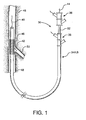
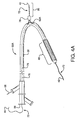
- the present invention provides an interventional delivery system 30 comprising a first catheter shaft 32, a second catheter assembly 34A or 34B, a first catheter hub assembly 36, a second catheter hub assembly 38, a bifurcated guidewire leading tip 40, a bifurcated guidewire reverse facing tip 42, a bifurcated guidewire proximal tip 44, and a device assembly 46.
- the interventional delivery system 30 is shown positioned in an anatomical main vessel 48 so that the device assembly 46 is positioned approximate to an anatomical side branch vessel 50.
- the device assembly 46 will be deployed to form a main body stent within the main vessel 48 along with an integrated side branch stent within the side branch vessel 50.
- Shown in Figures 2 through 9 are various sub-components and assemblies of the interventional delivery system 30 (of Figure 1 ).
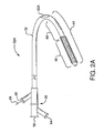
- Shown in Figure 2A is a first catheter assembly 52A having a first catheter hub assembly 36.
- the hub assembly 36 includes a perfusion port 54, a bifurcated guidewire port 56, a side branch deployment line 58 protruding from a deployment line port 60.
- the first catheter assembly 52A further comprises a first catheter shaft 32 that has an apex opening 62A. Apex opening 62A as shown is a cut-opening through the wall of the first catheter shaft 32.
- the first catheter shaft is shown bent about the apex opening 62A, forming a reverse facing segment 64.
- the reverse facing segment 64 has a side branch device portion 66 and a side branch device to apex opening separation length 68.
- a first catheter assembly 52B has a first catheter hub assembly 36.
- the hub assembly 36 includes a perfusion port 54, a bifurcated guidewire port 56, a side branch deployment line 58 protruding from a deployment line port 60.
- the first catheter assembly 52B further comprises a first catheter shaft 32 that has an apex opening 62B.
- Apex opening 62B as shown comprises the open ends of a cut catheter shaft 32. The two cut ends are joined at connection 70.
- the two cut shafts as shown form a reverse facing segment 64.
- the reverse facing segment 64 has a side branch device portion 66 and a side branch device to apex opening separation length 68.
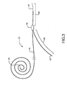
- a bifurcated guidewire assembly 72 having a proximal tip 44 and a main segment 76. Within the distal portion of the guidewire main segment 76 is a connection 78, defining a leading guidewire segment 80 and a reverse facing guidewire segment 82.
- the leading guidewire segment 30 has a leading tip 40 and the reverse facing guidewire segment has a reverse facing tip 42.
- FIG 4A shows a first catheter assembly (52A of Figure 2A ) combined with a bifurcated guidewire assembly (72 of Figure 3 ).
- a bifurcated guidewire assembly 72 positioned within a first catheter assembly 52A. Shown protruding from an apex opening 62A is the bifurcated guidewire connection 78 along with the leading guidewire segment 80.
- the proximal end 74 of the bifurcated guidewire protrudes from the bifurcated guidewire port 56 and the reverse facing tip 42 of the guidewire protrudes from the reverse facing segment of the first catheter.
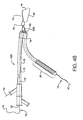
- Figure 4B shows a preferred first catheter assembly (52B of Figure 2B ) combined with a bifurcated guidewire assembly (72 of Figure 3 ).
- a bifurcated guidewire assembly 72 positioned within a first catheter assembly 52B. Shown protruding from an apex opening 62B is the bifurcated guidewire connection 78 along with the leading guidewire segment 80.
- the proximal end 74 of the bifurcated guidewire protrudes from the bifurcated guidewire port 56, and the reverse facing tip 42 of the guidewire protrudes from the reverse facing segment of the first catheter.
- the tube-to-tube connection 70 can include a friction-reducing component or feature to allow the deployment line 58 to easily slide against the tubes or apex opening as the deployment line is activated.
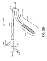
- Shown in Figure 5 are a partial cross-sectional view of the reverse facing segment 64 that includes a side branch device portion 66 and a side branch device to apex opening separation length 68. Shown is the bifurcated guidewire 72 reverse facing tip 42 exiting from an olive 88. Positioned onto a side branch accommodating segment 94 is a constrained, self-expanding side branch device 90. The side branch device 90 is held in a compressed state by a constraining sheath 92. Attached or integral to the constraining sheath is a side branch device deployment line 58.
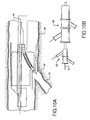
- FIGS 6A and 6B are side views of two embodiments of said second catheter. Shown in Figure 6A is said second catheter assembly 34A having a second catheter hub assembly 38.
- the second catheter hub assembly further includes a proximal perfusion port 54.
- the hub assembly is joined to a second catheter main body 96. Near the distal end of the second catheter main body 96 is a side branch device opening 98, formed by a cut-out portion of the catheter wall.
- the opening 98 allows a bifurcated guidewire and a side branch device to be subsequently advanced from the second catheter. After deployment, the bifurcated guidewire can be pulled through the opening 98 into the second catheter for removal.
- a capture tube portion 100 At the distal end of the second catheter main body is a capture tube portion 100. This tube portion "captures" the bifurcated guidewire after device deployment, allowing for a non-traumatic removal of the guidewire and delivery system.
- Figure 6B depicts an alternate embodiment of said second catheter assembly 34B.
- the distal end of the second catheter main body 96 is joined to the capture tube portion 100 by at least one main body to capture tube joining member 102.
- the main body 96 and the capture tube 102 are therefore separated and connected by the joining members 102.
- the gap between the main body and the capture tube forms an opening 98 functionally similar to the opening 98 shown in Figure 6A .
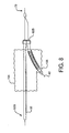
- Figure 7 is an isometric view of an expanded main body device 104.
- An aperture 106 is formed in the main body device wall, permitting a side branch device to be subsequently inserted through and attached to the aperture/main body.
- Figure 8 is a partial cross-sectional view of a main body device 104 surrounding a first catheter assembly 52B.
- a bifurcated guidewire 72 is positioned within the first catheter (as previously shown in Figure 4B ).
- a reverse facing portion of the first catheter having a constrained side branch device is shown protruding through an aperture 106 in the main body stent. Exiting from the reverse facing portion of the first catheter is the reverse facing tip 42 of the bifurcated guidewire. Also shown are the first catheter shaft 32 and the apex opening 62B.
- Figure 9 is a partial cross-sectional view of the components depicted in previous Figure 8 along with a second catheter 34B (refer to Figure 6B ).
- Shown is a second catheter main body 96, connected to a capture tube portion 100 by at least one joining member 102.
- the distal end of the bifurcated guidewire is shown positioned within the capture tube portion 100.
- the first catheter shaft 32 is shown positioned within the second catheter main body 96.
- a constraining sheath 92 and the attached or integral main body deployment line 109 are also shown.
- the reverse facing portion of the first catheter is shown protruding through an aperture 108 within the constraining sheath 92.
- FIG. 10 A sequence used to deliver and deploy main body and side branch stents according to the present invention is depicted in Figures 10 through 16 .
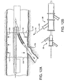
- Figure 10A is a partial cross-sectional view of the distal end of an interventional delivery system similar to that of Figure 1 .
- a device assembly is shown initially positioned in an anatomical main vessel 48 so that the device assembly is positioned approximate to an anatomical side branch vessel 50. Shown are a bifurcated guidewire leading tip 40 and a bifurcated guidewire reverse facing tip 42.
- the device assembly (46 of Figure 1 ) has been expanded to display the internal components as shown in Figure 9 .
- Figure 10B depicts the proximal end of the interventional delivery system, similar to that shown in Figure 1 . Shown are a first catheter hub assembly 36 and a second catheter hub assembly 38.
- Figures 11A and 11B show the bifurcated guidewire reverse facing tip 42 being advanced into the side branch vessel 50 along the direction indicated by arrow 110.
- the guidewire reverse facing tip 42 is advanced by pulling (in direction indicated by arrow 112 on the proximal end 74 of the guidewire.
- the two hub assemblies 36, 38 are held stationary as the proximal end of the guidewire is pulled.
- the guidewire leading tip 40 is advanced towards the apex opening 62B in the direction shown by arrow 114.
- the guidewire reverse facing tip 42 is therefore forced to advance into the side branch vessel 50 in the direction of arrow 110.
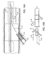
- the main body stent 104 is deployed by pulling on the main body stent deployment line 109 in the direction indicated by arrow 116.
- the main body stent is allowed to self-expand in the directions indicated by arrows 118.
- the two hub assemblies 36, 38 are held stationary as the deployment line is pulled. Note that the guidewire and/or the side branch device are positioned through the aperture 106 in the main body device 104.
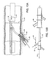
- the side branch device is then advanced into the side branch vessel, as depicted in Figures 13A and 13B .
- the side branch device is advanced along the direction indicated by arrow 120 by holding stationary the second catheter hub assembly 38 while concurrently pulling on the guidewire 44 and the first catheter hub assembly 36.
- the guidewire may be optionally locked onto the first catheter hub assembly 36 to facilitate this step.
- the distal tip of the guidewire 40 is pulled in the direction indicated by arrow 124, forcing the side branch device to advance partially through the main body device aperture 106 and into the side branch vasculature 50 in the direction 120.
- the side branch deployment line 58 is then pulled in the direction indicated by arrow 126, allowing the side branch device 66 to self-expand as indicated by arrows 128. Note that the side branch device is partially contained within and constrained by the main body device aperture 106. The two hub assemblies 36, 38 are held stationary as the deployment line is pulled.
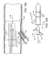
- the delivery system of the present invention is withdrawn from the vasculature by forcing the reverse facing portion of the first catheter 64 out of the expanded side branch device and into the capture tube 100 along the direction as indicated by arrows 130.
- the first catheter reverse facing portion is driven into the capture tube by pushing the first catheter hub assembly 36 along with the guidewire 44 along the direction as shown by arrows 132.
- the second catheter hub assembly 38 is held stationary as the first catheter hub assembly and the guidewire are advanced.
- the first catheter hub assembly 36, the guidewire proximal tip 44, and the second catheter hub assembly 38 are concurrently pulled in the direction as shown by arrows 134 of Figures 16A and 16B .
- the capture tube 100, containing the bifurcated guidewire and the reverse facing portion or the first catheter 64 are non-traumatically removed from the vasculature, leaving the expanded main body device 104 and the attached side branch device 66 in the vasculature.
- a main body device can have two, three, four, five, six or more side branch apertures.
- the various catheters of the present invention can incorporate more than one device; for example, a first catheter can incorporate two or more side branch devices.
- the sealing or interference fit between a main body and a side branch device can be enhanced by the incorporation of a "sealing sleeve". See for example US Patent No. 6,645,242 to Quinn for a disclosure of such sealing sleeves.
- Multiple sealing sleeves can be incorporated into a main body device to enhance the sealing or attachment of multiple side branch devices. Sealing sleeves can be "internal to" or “external to” the lumen of a main body stent and can be shaped and sized to seal a specifically configured side branch device.
- Stents used in the present invention can be bare (uncovered), coated with a variety of drug eluting, anti-thrombogenic or other coatings, or can include a partial or full cover (as in a stent graft).
- Anchoring mechanisms such as barbs, "fish-scales", biological attachment means, or other features can be incorporated into the main body and/or a side branch device to facilitate anchoring to the vasculature.
- Main body stents and/or side branch stents can have a uniform profile or have non-uniform profiles such as tapers, "trumpet-end” shapes, “dog-bone” shapes, curves or other profiles that enhance the device performance within a particular treatment site.
- Multiple devices of the present invention can be "ganged” or interconnected to form a multi-component system.
- Devices of the present invention can include features that allow or enhance the interconnection or "docking" between multiple devices.
- Radiopaque markers or indicators can be incorporated into a main body device, the various catheters used in the present invention and/or a side branch device to facilitate placement and visualization within the vasculature.
- Devices of the present invention can be used to treat non-vascular conduits, hollow or tubular parts of organs, such as bilary, bladder, urethra, gastrological, bronchi, bile, and other ducts.
- Devices of the present invention are particularly suited for, but not limited to, side branch vessels that have an "acute" angle from the main body (see for example Figure 1 ).
- Devices of the present invention can be balloon-expandable as well as self-expanding.
- the first catheter according to the present invention can incorporate a balloon (or balloons) and inflation lumens as required to expand a particular device.
- Combinations of self-expanding and balloon-expandable devices can be configured according to the present invention.
- separate balloon expanders can be used within the scope of the present invention as set forth in the appended claims.
- Catheter components of the present invention can be fabricated from common materials such as nylons, polycarbonates, polyethylenes, polypropylenes, polytetrafluoroethylenes, polyvinyl chlorides, polyurethanes, polysiloxanes, stainless steels, nitinols, or other biocompatible materials.
Claims (20)
- Système d'administration interventionnel, comprenant :un premier cathéter (32), comportant au niveau de son extrémité distale un segment de vaisseau de ramification latérale (66) ;un deuxième cathéter (34A, 34B), fixé autour du premier cathéter (32) et comportant au niveau de son extrémité distale un segment de vaisseau principal ; etun dispositif de vaisseau de ramification latérale (90), fixé sur le segment de vaisseau de ramification latérale du première cathéter, caractérisé en ce qu'il comporte un fil-guide bifurqué comportant deux pointes distales (40, 42), ledit segment de vaisseau de ramification latérale étant agencé entre lesdites deux pointes distales (40, 42).
- Système d'administration interventionnel selon la revendication 1, dans lequel les deux pointes distales sont orientées dans des directions opposées.
- Système d'administration interventionnel selon la revendication 1, dans lequel une des deux pointes distales constitue l'extrémité avant.
- Système d'administration interventionnel selon la revendication 3, dans lequel une des deux pointes distales facilite l'avance d'un cathéter.
- Système d'administration interventionnel selon la revendication 1, dans lequel une des deux pointes distales est une extrémité de pointe à orientation inverse.
- Extrémité de pointe à orientation inverse selon la revendication 5, dans laquelle l'extrémité de pointe à orientation inverse déborde du côté du segment du vaisseau principal.
- Extrémité de pointe à orientation inverse selon la revendication 5, dans laquelle l'extrémité de pointe à orientation inverse peut être rétractée à partir d'une ramification latérale.
- Système d'administration interventionnelle selon la revendication 1, comprenant en outre un tube de capture sur le deuxième cathéter.
- Tube de capture selon la revendication 8, dans lequel le tube de capture comporte une ouverture permettant le débordement de l'extrémité de pointe à orientation inverse du côté du tube de capture.
- Système d'administration interventionnel selon la revendication 8, dans lequel le tube de capture est orienté de sorte que la pointe d'extrémité avant et la pointe à orientation inverse peuvent être rétractées dans le tube de capture.
- Système d'administration interventionnel selon la revendication 1, comprenant
un dispositif de vaisseau principal (104), fixé sur le segment de vaisseau principal du deuxième cathéter ;
le dispositif de vaisseau principal (104) et le dispositif de vaisseau de ramification latérale (90) étant administrés de manière simultané à un site de traitement, le fil-guide bifurqué étant en outre configuré de sorte à se déplacer de manière coulissante dans le premier cathéter. - Système d'administration interventionnel selon la revendication 11, dans lequel une partie de l'extrémité distale du premier cathéter est repliée vers l'arrière sur elle-même.
- Système d'administration interventionnel selon la revendication 12, dans lequel le segment de vaisseau de ramification latérale comprend la partie du premier cathéter qui est repliée vers l'arrière sur elle-même.
- Système d'administration interventionnel selon la revendication 12, dans lequel une fil-guide bifurqué est agencé dans le premier cathéter.
- Système d'administration interventionnel selon la revendication 14, dans lequel le fil-guide bifurqué est avancé à travers le segment de ramification latérale du premier cathéter en exerçant une traction sur le fil-guide bifurqué.
- Système d'administration interventionnel selon la revendication 14, dans lequel le premier cathéter, le deuxième cathéter et le fil-guide bifurqué sont adaptés pour être administrés de manière simultanée sur un site de traitement.
- Système d'administration interventionnel selon la revendication 14, dans lequel le premier cathéter, le deuxième cathéter et le fil-guide bifurqué peuvent en outre être déplacés, au moins en partie, de manière indépendante les uns des autres.
- Système d'administration interventionnel selon la revendication 11, dans lequel de multiples dispositifs sont montés sur le premier cathéter.
- Système d'administration interventionnel selon la revendication 18, dans lequel le premier cathéter comporte de multiples extrémités distales, permettant l'administration d'un dispositif vasculaire à un vaisseau à ramification aigue.
- Système d'administration interventionnel selon la revendication 11, dans lequel le deuxième cathéter comporte une ouverture dans une paroi latérale près de l'extrémité distale du deuxième cathéter, pour permettre le passage du segment de vaisseau de ramification latérale du premier cathéter.
Applications Claiming Priority (2)
| Application Number | Priority Date | Filing Date | Title |
|---|---|---|---|
| US11/474,165 US7771465B2 (en) | 2006-06-23 | 2006-06-23 | Branched stent delivery system |
| PCT/US2007/014338 WO2008002426A1 (fr) | 2006-06-23 | 2007-06-20 | Système de distribution de stent à branches |
Publications (2)
| Publication Number | Publication Date |
|---|---|
| EP2032090A1 EP2032090A1 (fr) | 2009-03-11 |
| EP2032090B1 true EP2032090B1 (fr) | 2013-05-29 |
Family
ID=38616001
Family Applications (1)
| Application Number | Title | Priority Date | Filing Date |
|---|---|---|---|
| EP07796274.4A Active EP2032090B1 (fr) | 2006-06-23 | 2007-06-20 | Système de distribution de stent à branches |
Country Status (7)
| Country | Link |
|---|---|
| US (4) | US7771465B2 (fr) |
| EP (1) | EP2032090B1 (fr) |
| JP (1) | JP5260509B2 (fr) |
| AU (1) | AU2007265592B2 (fr) |
| CA (1) | CA2656059C (fr) |
| ES (1) | ES2424656T3 (fr) |
| WO (1) | WO2008002426A1 (fr) |
Families Citing this family (27)
| Publication number | Priority date | Publication date | Assignee | Title |
|---|---|---|---|---|
| US7771465B2 (en) | 2006-06-23 | 2010-08-10 | Gore Enterprise Holdings, Inc. | Branched stent delivery system |
| US20100324664A1 (en) * | 2006-10-18 | 2010-12-23 | Asher Holzer | Bifurcated Stent Assemblies |
| US20080114444A1 (en) * | 2006-11-09 | 2008-05-15 | Chun Ho Yu | Modular stent graft and delivery system |
| US20090099648A1 (en) * | 2006-11-09 | 2009-04-16 | Chun Ho Yu | Modular stent graft and delivery system |
| CN101715329B (zh) | 2007-03-05 | 2012-11-14 | 恩多斯潘有限公司 | 多组件可膨胀式支持性分叉腔内移植物和用于使用该移植物的方法 |
| US8273115B2 (en) | 2007-04-24 | 2012-09-25 | W. L. Gore & Associates, Inc. | Side branched endoluminal prostheses and methods of delivery thereof |
| WO2009105699A1 (fr) | 2008-02-22 | 2009-08-27 | Endologix, Inc. | Conception et procédé de mise en place d’un greffon ou d’un système de greffons |
| EP2429452B1 (fr) | 2009-04-28 | 2020-01-15 | Endologix, Inc. | Système de prothèse endoluminale |
| WO2010150208A2 (fr) | 2009-06-23 | 2010-12-29 | Endospan Ltd. | Prothèses vasculaires utilisées pour le traitement des anévrismes |
| AU2011215968B2 (en) | 2010-02-09 | 2013-08-01 | Cook Medical Technologies Llc | Thoracic aorta stent graft |
| EP2635241B1 (fr) | 2010-11-02 | 2019-02-20 | Endologix, Inc. | Appareil de disposition de greffe ou de système de greffe |
| US20120130475A1 (en) | 2010-11-16 | 2012-05-24 | Shaw Edward E | Sleeves for expandable medical devices |
| WO2013030818A2 (fr) | 2011-08-28 | 2013-03-07 | Endospan Ltd. | Endoprothèses couvertes à déplacement axial et radial variable après déploiement |
| WO2013065040A1 (fr) | 2011-10-30 | 2013-05-10 | Endospan Ltd. | Greffon-endoprothèse à trois colliers |
| US8945200B1 (en) | 2011-11-16 | 2015-02-03 | W. L. Gore & Associates, Inc. | Iliac bifurcated endoprosthesis medical apparatus and method of deploying same |
| WO2013084235A2 (fr) | 2011-12-04 | 2013-06-13 | Endospan Ltd. | Système de greffon de stent ramifié |
| US9770350B2 (en) | 2012-05-15 | 2017-09-26 | Endospan Ltd. | Stent-graft with fixation elements that are radially confined for delivery |
| WO2014108895A2 (fr) | 2013-01-08 | 2014-07-17 | Endospan Ltd. | Minimisation de la migration d'une endoprothèse au cours de l'implantation |
| US10603197B2 (en) | 2013-11-19 | 2020-03-31 | Endospan Ltd. | Stent system with radial-expansion locking |
| US10758387B2 (en) | 2014-10-16 | 2020-09-01 | Cook Medical Technologies Llc | Endovascular stent graft assembly and delivery device |
| US10959826B2 (en) | 2014-10-16 | 2021-03-30 | Cook Medical Technology LLC | Support structure for scalloped grafts |
| JP6960334B2 (ja) | 2014-12-04 | 2021-11-05 | トリバスキュラー インコーポレイテッド | 内腸骨動脈保存器具および方法 |
| WO2016098113A1 (fr) | 2014-12-18 | 2016-06-23 | Endospan Ltd. | Stent-greffe endovasculaire avec tube latéral résistant à la fatigue |
| US11129737B2 (en) | 2015-06-30 | 2021-09-28 | Endologix Llc | Locking assembly for coupling guidewire to delivery system |
| AU2017326087B2 (en) | 2016-09-15 | 2020-03-26 | W. L. Gore & Associates, Inc. | Staged deployment of expandable implant |
| US11439496B2 (en) | 2017-10-20 | 2022-09-13 | SB-Kawasumi Laboratories, Inc. | Tubular therapeutic implement, tubular therapeutic implement set, and device for indwelling tubular therapeutic implement |
| EP3738548A4 (fr) | 2018-01-12 | 2021-09-22 | Kawasumi Laboratories, Inc. | Outil de placement intravasculaire et système de placement intravasculaire |
Family Cites Families (43)
| Publication number | Priority date | Publication date | Assignee | Title |
|---|---|---|---|---|
| US669718A (en) * | 1900-12-03 | 1901-03-12 | Lewis O Whittemore | Feeder for corn-shellers. |
| US5476453A (en) * | 1994-05-20 | 1995-12-19 | Mehta; Sameer | Catheter for simultaneous right and left coronary cannulization |
| US6045557A (en) * | 1995-11-10 | 2000-04-04 | Baxter International Inc. | Delivery catheter and method for positioning an intraluminal graft |
| US5824040A (en) * | 1995-12-01 | 1998-10-20 | Medtronic, Inc. | Endoluminal prostheses and therapies for highly variable body lumens |
| US5676697A (en) * | 1996-07-29 | 1997-10-14 | Cardiovascular Dynamics, Inc. | Two-piece, bifurcated intraluminal graft for repair of aneurysm |
| US8211167B2 (en) * | 1999-12-06 | 2012-07-03 | Boston Scientific Scimed, Inc. | Method of using a catheter with attached flexible side sheath |
| ES2273363T3 (es) * | 1996-11-04 | 2007-05-01 | Advanced Stent Technologies, Inc. | Doble stent extensible. |
| US5860998A (en) * | 1996-11-25 | 1999-01-19 | C. R. Bard, Inc. | Deployment device for tubular expandable prosthesis |
| US6096073A (en) * | 1997-02-25 | 2000-08-01 | Scimed Life Systems, Inc. | Method of deploying a stent at a lesion site located at a bifurcation in a parent vessel |
| US5824055A (en) * | 1997-03-25 | 1998-10-20 | Endotex Interventional Systems, Inc. | Stent graft delivery system and methods of use |
| US5947953A (en) * | 1997-08-06 | 1999-09-07 | Hemocleanse, Inc. | Splittable multiple catheter assembly and methods of inserting the same |
| JP4121615B2 (ja) * | 1997-10-31 | 2008-07-23 | オリンパス株式会社 | 内視鏡 |
| US6156016A (en) * | 1998-01-06 | 2000-12-05 | Maginot Vascular Systems | Catheter systems and associated methods utilizing removable inner catheter or catheters |
| US6117117A (en) * | 1998-08-24 | 2000-09-12 | Advanced Cardiovascular Systems, Inc. | Bifurcated catheter assembly |
| EP1043041A4 (fr) | 1998-10-29 | 2008-12-17 | Kanji Inoue | Dispositif de guidage d'instruments |
| US6475222B1 (en) * | 1998-11-06 | 2002-11-05 | St. Jude Medical Atg, Inc. | Minimally invasive revascularization apparatus and methods |
| US6261316B1 (en) * | 1999-03-11 | 2001-07-17 | Endologix, Inc. | Single puncture bifurcation graft deployment system |
| US6440161B1 (en) * | 1999-07-07 | 2002-08-27 | Endologix, Inc. | Dual wire placement catheter |
| DE19938377A1 (de) * | 1999-08-06 | 2001-03-01 | Biotronik Mess & Therapieg | Stent für Gefässverzweigungen |
| US6849087B1 (en) * | 1999-10-06 | 2005-02-01 | Timothy A. M. Chuter | Device and method for staged implantation of a graft for vascular repair |
| AU1723201A (en) | 1999-11-18 | 2001-05-30 | Petrus Besselink | Method for placing bifurcated stents |
| EP2113225B1 (fr) | 2000-03-30 | 2010-11-10 | Teramed Corporation | Cathéter pour la mise en place d'une endoprothèse bifurquée |
| US20020072712A1 (en) * | 2000-10-12 | 2002-06-13 | Nool Jeffrey A. | Medical wire introducer and protective sheath |
| AU2001296716A1 (en) | 2000-10-13 | 2002-04-22 | Rex Medical, Lp | Covered stents with side branch |
| US6645242B1 (en) | 2000-12-11 | 2003-11-11 | Stephen F. Quinn | Bifurcated side-access intravascular stent graft |
| US20040138734A1 (en) * | 2001-04-11 | 2004-07-15 | Trivascular, Inc. | Delivery system and method for bifurcated graft |
| US6752825B2 (en) * | 2001-10-02 | 2004-06-22 | Scimed Life Systems, Inc | Nested stent apparatus |
| AU2003216517A1 (en) * | 2002-03-07 | 2003-09-22 | Cordis Corporation | Iliac bifurcation balloon catheter |
| US20030204246A1 (en) * | 2002-04-25 | 2003-10-30 | Jack Chu | Aneurysm treatment system and method |
| US6676694B1 (en) * | 2002-06-06 | 2004-01-13 | Mitchell Weiss | Method for installing a stent graft |
| US6833003B2 (en) | 2002-06-24 | 2004-12-21 | Cordis Neurovascular | Expandable stent and delivery system |
| AU2002951147A0 (en) | 2002-09-02 | 2002-09-19 | Cook Incorporated | Branch grafting device and method |
| US7993325B2 (en) * | 2002-09-20 | 2011-08-09 | Angio Dynamics, Inc. | Renal infusion systems and methods |
| US20050197624A1 (en) * | 2004-03-04 | 2005-09-08 | Flowmedica, Inc. | Sheath for use in peripheral interventions |
| US7300460B2 (en) * | 2002-12-31 | 2007-11-27 | Counter Clockwise, Inc. | Bifurcated guidewire and methods of use |
| US7753945B2 (en) | 2003-01-17 | 2010-07-13 | Gore Enterprise Holdings, Inc. | Deployment system for an endoluminal device |
| US20070078506A1 (en) * | 2004-04-13 | 2007-04-05 | Mccormick Paul | Method and apparatus for decompressing aneurysms |
| US7527606B2 (en) * | 2004-05-27 | 2009-05-05 | Abbott Laboratories | Catheter having main body portion with coil-defined guidewire passage |
| US7771401B2 (en) * | 2006-06-08 | 2010-08-10 | Angiodynamics, Inc. | Selective renal cannulation and infusion systems and methods |
| US7771465B2 (en) * | 2006-06-23 | 2010-08-10 | Gore Enterprise Holdings, Inc. | Branched stent delivery system |
| US8029558B2 (en) * | 2006-07-07 | 2011-10-04 | Abbott Cardiovascular Systems, Inc. | Stent and catheter assembly and method for treating bifurcations |
| US8523931B2 (en) * | 2007-01-12 | 2013-09-03 | Endologix, Inc. | Dual concentric guidewire and methods of bifurcated graft deployment |
| US20090259285A1 (en) * | 2008-04-10 | 2009-10-15 | Medtronic Vascular, Inc. | Bifurcated Delivery System |
-
2006
- 2006-06-23 US US11/474,165 patent/US7771465B2/en active Active
- 2006-11-09 US US11/595,150 patent/US8080049B2/en active Active
-
2007
- 2007-06-20 EP EP07796274.4A patent/EP2032090B1/fr active Active
- 2007-06-20 CA CA2656059A patent/CA2656059C/fr active Active
- 2007-06-20 JP JP2009516553A patent/JP5260509B2/ja not_active Expired - Fee Related
- 2007-06-20 WO PCT/US2007/014338 patent/WO2008002426A1/fr active Application Filing
- 2007-06-20 AU AU2007265592A patent/AU2007265592B2/en not_active Ceased
- 2007-06-20 ES ES07796274T patent/ES2424656T3/es active Active
-
2009
- 2009-11-18 US US12/620,634 patent/US20100069853A1/en not_active Abandoned
-
2013
- 2013-05-20 US US13/898,315 patent/US8864812B2/en active Active
Also Published As
| Publication number | Publication date |
|---|---|
| EP2032090A1 (fr) | 2009-03-11 |
| AU2007265592A1 (en) | 2008-01-03 |
| JP2009540930A (ja) | 2009-11-26 |
| US7771465B2 (en) | 2010-08-10 |
| US20070299494A1 (en) | 2007-12-27 |
| US20130253630A1 (en) | 2013-09-26 |
| US8080049B2 (en) | 2011-12-20 |
| AU2007265592B2 (en) | 2011-10-27 |
| US20100069853A1 (en) | 2010-03-18 |
| US8864812B2 (en) | 2014-10-21 |
| CA2656059C (fr) | 2012-10-09 |
| JP5260509B2 (ja) | 2013-08-14 |
| WO2008002426A1 (fr) | 2008-01-03 |
| CA2656059A1 (fr) | 2008-01-03 |
| ES2424656T3 (es) | 2013-10-07 |
| US20070299495A1 (en) | 2007-12-27 |
Similar Documents
| Publication | Publication Date | Title |
|---|---|---|
| EP2032090B1 (fr) | Système de distribution de stent à branches | |
| US20210169670A1 (en) | Stent cannulation guiding device for bifurcated stent and method of use | |
| US8491646B2 (en) | Stent graft | |
| EP3017790B1 (fr) | Ensemble greffe d'endoprothèse endovasculaire et dispositif d'administration | |
| JP2016128131A (ja) | 予めカニューレが挿入された開窓部 | |
| AU2018226379B2 (en) | Stent cannulation guiding device and method of use | |
| EP2792336B1 (fr) | Système de livraison comprenant dispositif de branchement iliaque préchargé | |
| EP2777605A1 (fr) | Greffes endovasculaires permettant de traiter les artères iliaques et procédés d'administration et déploiement correspondant | |
| EP2799038B1 (fr) | Système de pose de prothèse endoluminale | |
| EP1813232B1 (fr) | Déploiement de cathéter pour des dispositifs d'implant médical |
Legal Events
| Date | Code | Title | Description |
|---|---|---|---|
| PUAI | Public reference made under article 153(3) epc to a published international application that has entered the european phase |
Free format text: ORIGINAL CODE: 0009012 |
|
| 17P | Request for examination filed |
Effective date: 20081223 |
|
| AK | Designated contracting states |
Kind code of ref document: A1 Designated state(s): AT BE BG CH CY CZ DE DK EE ES FI FR GB GR HU IE IS IT LI LT LU LV MC MT NL PL PT RO SE SI SK TR |
|
| AX | Request for extension of the european patent |
Extension state: AL BA HR MK RS |
|
| 17Q | First examination report despatched |
Effective date: 20100129 |
|
| DAX | Request for extension of the european patent (deleted) | ||
| RIC1 | Information provided on ipc code assigned before grant |
Ipc: A61F 2/84 20060101AFI20120917BHEP |
|
| GRAP | Despatch of communication of intention to grant a patent |
Free format text: ORIGINAL CODE: EPIDOSNIGR1 |
|
| GRAS | Grant fee paid |
Free format text: ORIGINAL CODE: EPIDOSNIGR3 |
|
| REG | Reference to a national code |
Ref country code: DE Ref legal event code: R079 Ref document number: 602007030776 Country of ref document: DE Free format text: PREVIOUS MAIN CLASS: A61F0002840000 Ipc: A61F0002954000 |
|
| GRAA | (expected) grant |
Free format text: ORIGINAL CODE: 0009210 |
|
| AK | Designated contracting states |
Kind code of ref document: B1 Designated state(s): AT BE BG CH CY CZ DE DK EE ES FI FR GB GR HU IE IS IT LI LT LU LV MC MT NL PL PT RO SE SI SK TR |
|
| REG | Reference to a national code |
Ref country code: GB Ref legal event code: FG4D |
|
| RIC1 | Information provided on ipc code assigned before grant |
Ipc: A61F 2/954 20130101AFI20130422BHEP |
|
| REG | Reference to a national code |
Ref country code: CH Ref legal event code: EP |
|
| REG | Reference to a national code |
Ref country code: AT Ref legal event code: REF Ref document number: 613895 Country of ref document: AT Kind code of ref document: T Effective date: 20130615 |
|
| REG | Reference to a national code |
Ref country code: IE Ref legal event code: FG4D |
|
| REG | Reference to a national code |
Ref country code: DE Ref legal event code: R096 Ref document number: 602007030776 Country of ref document: DE Effective date: 20130725 |
|
| REG | Reference to a national code |
Ref country code: ES Ref legal event code: FG2A Ref document number: 2424656 Country of ref document: ES Kind code of ref document: T3 Effective date: 20131007 |
|
| REG | Reference to a national code |
Ref country code: AT Ref legal event code: MK05 Ref document number: 613895 Country of ref document: AT Kind code of ref document: T Effective date: 20130529 |
|
| REG | Reference to a national code |
Ref country code: LT Ref legal event code: MG4D |
|
| PG25 | Lapsed in a contracting state [announced via postgrant information from national office to epo] |
Ref country code: FI Free format text: LAPSE BECAUSE OF FAILURE TO SUBMIT A TRANSLATION OF THE DESCRIPTION OR TO PAY THE FEE WITHIN THE PRESCRIBED TIME-LIMIT Effective date: 20130529 Ref country code: AT Free format text: LAPSE BECAUSE OF FAILURE TO SUBMIT A TRANSLATION OF THE DESCRIPTION OR TO PAY THE FEE WITHIN THE PRESCRIBED TIME-LIMIT Effective date: 20130529 Ref country code: IS Free format text: LAPSE BECAUSE OF FAILURE TO SUBMIT A TRANSLATION OF THE DESCRIPTION OR TO PAY THE FEE WITHIN THE PRESCRIBED TIME-LIMIT Effective date: 20130929 Ref country code: GR Free format text: LAPSE BECAUSE OF FAILURE TO SUBMIT A TRANSLATION OF THE DESCRIPTION OR TO PAY THE FEE WITHIN THE PRESCRIBED TIME-LIMIT Effective date: 20130830 Ref country code: SE Free format text: LAPSE BECAUSE OF FAILURE TO SUBMIT A TRANSLATION OF THE DESCRIPTION OR TO PAY THE FEE WITHIN THE PRESCRIBED TIME-LIMIT Effective date: 20130529 Ref country code: PT Free format text: LAPSE BECAUSE OF FAILURE TO SUBMIT A TRANSLATION OF THE DESCRIPTION OR TO PAY THE FEE WITHIN THE PRESCRIBED TIME-LIMIT Effective date: 20130930 Ref country code: LT Free format text: LAPSE BECAUSE OF FAILURE TO SUBMIT A TRANSLATION OF THE DESCRIPTION OR TO PAY THE FEE WITHIN THE PRESCRIBED TIME-LIMIT Effective date: 20130529 Ref country code: SI Free format text: LAPSE BECAUSE OF FAILURE TO SUBMIT A TRANSLATION OF THE DESCRIPTION OR TO PAY THE FEE WITHIN THE PRESCRIBED TIME-LIMIT Effective date: 20130529 |
|
| REG | Reference to a national code |
Ref country code: NL Ref legal event code: VDEP Effective date: 20130529 |
|
| PG25 | Lapsed in a contracting state [announced via postgrant information from national office to epo] |
Ref country code: BG Free format text: LAPSE BECAUSE OF FAILURE TO SUBMIT A TRANSLATION OF THE DESCRIPTION OR TO PAY THE FEE WITHIN THE PRESCRIBED TIME-LIMIT Effective date: 20130829 Ref country code: PL Free format text: LAPSE BECAUSE OF FAILURE TO SUBMIT A TRANSLATION OF THE DESCRIPTION OR TO PAY THE FEE WITHIN THE PRESCRIBED TIME-LIMIT Effective date: 20130529 |
|
| PG25 | Lapsed in a contracting state [announced via postgrant information from national office to epo] |
Ref country code: LV Free format text: LAPSE BECAUSE OF FAILURE TO SUBMIT A TRANSLATION OF THE DESCRIPTION OR TO PAY THE FEE WITHIN THE PRESCRIBED TIME-LIMIT Effective date: 20130529 |
|
| PG25 | Lapsed in a contracting state [announced via postgrant information from national office to epo] |
Ref country code: SK Free format text: LAPSE BECAUSE OF FAILURE TO SUBMIT A TRANSLATION OF THE DESCRIPTION OR TO PAY THE FEE WITHIN THE PRESCRIBED TIME-LIMIT Effective date: 20130529 Ref country code: CZ Free format text: LAPSE BECAUSE OF FAILURE TO SUBMIT A TRANSLATION OF THE DESCRIPTION OR TO PAY THE FEE WITHIN THE PRESCRIBED TIME-LIMIT Effective date: 20130529 Ref country code: BE Free format text: LAPSE BECAUSE OF FAILURE TO SUBMIT A TRANSLATION OF THE DESCRIPTION OR TO PAY THE FEE WITHIN THE PRESCRIBED TIME-LIMIT Effective date: 20130529 Ref country code: EE Free format text: LAPSE BECAUSE OF FAILURE TO SUBMIT A TRANSLATION OF THE DESCRIPTION OR TO PAY THE FEE WITHIN THE PRESCRIBED TIME-LIMIT Effective date: 20130529 Ref country code: DK Free format text: LAPSE BECAUSE OF FAILURE TO SUBMIT A TRANSLATION OF THE DESCRIPTION OR TO PAY THE FEE WITHIN THE PRESCRIBED TIME-LIMIT Effective date: 20130529 |
|
| REG | Reference to a national code |
Ref country code: CH Ref legal event code: PL |
|
| PG25 | Lapsed in a contracting state [announced via postgrant information from national office to epo] |
Ref country code: RO Free format text: LAPSE BECAUSE OF FAILURE TO SUBMIT A TRANSLATION OF THE DESCRIPTION OR TO PAY THE FEE WITHIN THE PRESCRIBED TIME-LIMIT Effective date: 20130529 Ref country code: MC Free format text: LAPSE BECAUSE OF FAILURE TO SUBMIT A TRANSLATION OF THE DESCRIPTION OR TO PAY THE FEE WITHIN THE PRESCRIBED TIME-LIMIT Effective date: 20130529 Ref country code: NL Free format text: LAPSE BECAUSE OF FAILURE TO SUBMIT A TRANSLATION OF THE DESCRIPTION OR TO PAY THE FEE WITHIN THE PRESCRIBED TIME-LIMIT Effective date: 20130529 |
|
| PLBE | No opposition filed within time limit |
Free format text: ORIGINAL CODE: 0009261 |
|
| STAA | Information on the status of an ep patent application or granted ep patent |
Free format text: STATUS: NO OPPOSITION FILED WITHIN TIME LIMIT |
|
| PG25 | Lapsed in a contracting state [announced via postgrant information from national office to epo] |
Ref country code: CH Free format text: LAPSE BECAUSE OF NON-PAYMENT OF DUE FEES Effective date: 20130630 Ref country code: LI Free format text: LAPSE BECAUSE OF NON-PAYMENT OF DUE FEES Effective date: 20130630 |
|
| 26N | No opposition filed |
Effective date: 20140303 |
|
| REG | Reference to a national code |
Ref country code: DE Ref legal event code: R097 Ref document number: 602007030776 Country of ref document: DE Effective date: 20140303 |
|
| PG25 | Lapsed in a contracting state [announced via postgrant information from national office to epo] |
Ref country code: MT Free format text: LAPSE BECAUSE OF FAILURE TO SUBMIT A TRANSLATION OF THE DESCRIPTION OR TO PAY THE FEE WITHIN THE PRESCRIBED TIME-LIMIT Effective date: 20130529 |
|
| REG | Reference to a national code |
Ref country code: FR Ref legal event code: PLFP Year of fee payment: 9 |
|
| PG25 | Lapsed in a contracting state [announced via postgrant information from national office to epo] |
Ref country code: CY Free format text: LAPSE BECAUSE OF FAILURE TO SUBMIT A TRANSLATION OF THE DESCRIPTION OR TO PAY THE FEE WITHIN THE PRESCRIBED TIME-LIMIT Effective date: 20130529 Ref country code: TR Free format text: LAPSE BECAUSE OF FAILURE TO SUBMIT A TRANSLATION OF THE DESCRIPTION OR TO PAY THE FEE WITHIN THE PRESCRIBED TIME-LIMIT Effective date: 20130529 |
|
| PG25 | Lapsed in a contracting state [announced via postgrant information from national office to epo] |
Ref country code: LU Free format text: LAPSE BECAUSE OF NON-PAYMENT OF DUE FEES Effective date: 20130620 Ref country code: HU Free format text: LAPSE BECAUSE OF FAILURE TO SUBMIT A TRANSLATION OF THE DESCRIPTION OR TO PAY THE FEE WITHIN THE PRESCRIBED TIME-LIMIT; INVALID AB INITIO Effective date: 20070620 |
|
| REG | Reference to a national code |
Ref country code: GB Ref legal event code: 732E Free format text: REGISTERED BETWEEN 20150723 AND 20150729 |
|
| REG | Reference to a national code |
Ref country code: DE Ref legal event code: R082 Ref document number: 602007030776 Country of ref document: DE Representative=s name: MARKS & CLERK (LUXEMBOURG) LLP, LU Ref country code: DE Ref legal event code: R081 Ref document number: 602007030776 Country of ref document: DE Owner name: W.L. GORE & ASSOCIATES, INC., NEWARK, US Free format text: FORMER OWNER: GORE ENTERPRISE HOLDINGS, INC., NEWARK, DEL., US |
|
| REG | Reference to a national code |
Ref country code: FR Ref legal event code: PLFP Year of fee payment: 10 |
|
| REG | Reference to a national code |
Ref country code: FR Ref legal event code: TP Owner name: W.L. GORE & ASSOCIATES, INC., US Effective date: 20160510 |
|
| REG | Reference to a national code |
Ref country code: FR Ref legal event code: PLFP Year of fee payment: 11 |
|
| REG | Reference to a national code |
Ref country code: FR Ref legal event code: PLFP Year of fee payment: 12 |
|
| PGFP | Annual fee paid to national office [announced via postgrant information from national office to epo] |
Ref country code: IT Payment date: 20220518 Year of fee payment: 16 Ref country code: IE Payment date: 20220519 Year of fee payment: 16 |
|
| P01 | Opt-out of the competence of the unified patent court (upc) registered |
Effective date: 20230516 |
|
| PGFP | Annual fee paid to national office [announced via postgrant information from national office to epo] |
Ref country code: FR Payment date: 20230523 Year of fee payment: 17 Ref country code: DE Payment date: 20230523 Year of fee payment: 17 |
|
| PGFP | Annual fee paid to national office [announced via postgrant information from national office to epo] |
Ref country code: GB Payment date: 20230523 Year of fee payment: 17 Ref country code: ES Payment date: 20230703 Year of fee payment: 17 |
|
| REG | Reference to a national code |
Ref country code: IE Ref legal event code: MM4A |
|
| PG25 | Lapsed in a contracting state [announced via postgrant information from national office to epo] |
Ref country code: IE Free format text: LAPSE BECAUSE OF NON-PAYMENT OF DUE FEES Effective date: 20230620 |