EP2032030B1 - Solution pour la surveillance interne du corps - Google Patents
Solution pour la surveillance interne du corps Download PDFInfo
- Publication number
- EP2032030B1 EP2032030B1 EP07748306.3A EP07748306A EP2032030B1 EP 2032030 B1 EP2032030 B1 EP 2032030B1 EP 07748306 A EP07748306 A EP 07748306A EP 2032030 B1 EP2032030 B1 EP 2032030B1
- Authority
- EP
- European Patent Office
- Prior art keywords
- processing unit
- signals
- microwave
- status
- data
- Prior art date
- Legal status (The legal status is an assumption and is not a legal conclusion. Google has not performed a legal analysis and makes no representation as to the accuracy of the status listed.)
- Active
Links
Images

Classifications
-
- A—HUMAN NECESSITIES
- A61—MEDICAL OR VETERINARY SCIENCE; HYGIENE
- A61B—DIAGNOSIS; SURGERY; IDENTIFICATION
- A61B5/00—Measuring for diagnostic purposes; Identification of persons
- A61B5/05—Detecting, measuring or recording for diagnosis by means of electric currents or magnetic fields; Measuring using microwaves or radio waves
- A61B5/0507—Detecting, measuring or recording for diagnosis by means of electric currents or magnetic fields; Measuring using microwaves or radio waves using microwaves or terahertz waves
-
- A—HUMAN NECESSITIES
- A61—MEDICAL OR VETERINARY SCIENCE; HYGIENE
- A61B—DIAGNOSIS; SURGERY; IDENTIFICATION
- A61B5/00—Measuring for diagnostic purposes; Identification of persons
- A61B5/40—Detecting, measuring or recording for evaluating the nervous system
- A61B5/4076—Diagnosing or monitoring particular conditions of the nervous system
-
- A—HUMAN NECESSITIES
- A61—MEDICAL OR VETERINARY SCIENCE; HYGIENE
- A61F—FILTERS IMPLANTABLE INTO BLOOD VESSELS; PROSTHESES; DEVICES PROVIDING PATENCY TO, OR PREVENTING COLLAPSING OF, TUBULAR STRUCTURES OF THE BODY, e.g. STENTS; ORTHOPAEDIC, NURSING OR CONTRACEPTIVE DEVICES; FOMENTATION; TREATMENT OR PROTECTION OF EYES OR EARS; BANDAGES, DRESSINGS OR ABSORBENT PADS; FIRST-AID KITS
- A61F2/00—Filters implantable into blood vessels; Prostheses, i.e. artificial substitutes or replacements for parts of the body; Appliances for connecting them with the body; Devices providing patency to, or preventing collapsing of, tubular structures of the body, e.g. stents
- A61F2/02—Prostheses implantable into the body
- A61F2/30—Joints
- A61F2/46—Special tools or methods for implanting or extracting artificial joints, accessories, bone grafts or substitutes, or particular adaptations therefor
- A61F2/4657—Measuring instruments used for implanting artificial joints
-
- A—HUMAN NECESSITIES
- A61—MEDICAL OR VETERINARY SCIENCE; HYGIENE
- A61B—DIAGNOSIS; SURGERY; IDENTIFICATION
- A61B5/00—Measuring for diagnostic purposes; Identification of persons
- A61B5/45—For evaluating or diagnosing the musculoskeletal system or teeth
- A61B5/4528—Joints
-
- A—HUMAN NECESSITIES
- A61—MEDICAL OR VETERINARY SCIENCE; HYGIENE
- A61B—DIAGNOSIS; SURGERY; IDENTIFICATION
- A61B5/00—Measuring for diagnostic purposes; Identification of persons
- A61B5/72—Signal processing specially adapted for physiological signals or for diagnostic purposes
- A61B5/7203—Signal processing specially adapted for physiological signals or for diagnostic purposes for noise prevention, reduction or removal
- A61B5/7207—Signal processing specially adapted for physiological signals or for diagnostic purposes for noise prevention, reduction or removal of noise induced by motion artifacts
-
- A—HUMAN NECESSITIES
- A61—MEDICAL OR VETERINARY SCIENCE; HYGIENE
- A61F—FILTERS IMPLANTABLE INTO BLOOD VESSELS; PROSTHESES; DEVICES PROVIDING PATENCY TO, OR PREVENTING COLLAPSING OF, TUBULAR STRUCTURES OF THE BODY, e.g. STENTS; ORTHOPAEDIC, NURSING OR CONTRACEPTIVE DEVICES; FOMENTATION; TREATMENT OR PROTECTION OF EYES OR EARS; BANDAGES, DRESSINGS OR ABSORBENT PADS; FIRST-AID KITS
- A61F2/00—Filters implantable into blood vessels; Prostheses, i.e. artificial substitutes or replacements for parts of the body; Appliances for connecting them with the body; Devices providing patency to, or preventing collapsing of, tubular structures of the body, e.g. stents
- A61F2/02—Prostheses implantable into the body
- A61F2/30—Joints
- A61F2/32—Joints for the hip
-
- A—HUMAN NECESSITIES
- A61—MEDICAL OR VETERINARY SCIENCE; HYGIENE
- A61F—FILTERS IMPLANTABLE INTO BLOOD VESSELS; PROSTHESES; DEVICES PROVIDING PATENCY TO, OR PREVENTING COLLAPSING OF, TUBULAR STRUCTURES OF THE BODY, e.g. STENTS; ORTHOPAEDIC, NURSING OR CONTRACEPTIVE DEVICES; FOMENTATION; TREATMENT OR PROTECTION OF EYES OR EARS; BANDAGES, DRESSINGS OR ABSORBENT PADS; FIRST-AID KITS
- A61F2/00—Filters implantable into blood vessels; Prostheses, i.e. artificial substitutes or replacements for parts of the body; Appliances for connecting them with the body; Devices providing patency to, or preventing collapsing of, tubular structures of the body, e.g. stents
- A61F2/02—Prostheses implantable into the body
- A61F2/48—Operating or control means, e.g. from outside the body, control of sphincters
-
- A—HUMAN NECESSITIES
- A61—MEDICAL OR VETERINARY SCIENCE; HYGIENE
- A61F—FILTERS IMPLANTABLE INTO BLOOD VESSELS; PROSTHESES; DEVICES PROVIDING PATENCY TO, OR PREVENTING COLLAPSING OF, TUBULAR STRUCTURES OF THE BODY, e.g. STENTS; ORTHOPAEDIC, NURSING OR CONTRACEPTIVE DEVICES; FOMENTATION; TREATMENT OR PROTECTION OF EYES OR EARS; BANDAGES, DRESSINGS OR ABSORBENT PADS; FIRST-AID KITS
- A61F2/00—Filters implantable into blood vessels; Prostheses, i.e. artificial substitutes or replacements for parts of the body; Appliances for connecting them with the body; Devices providing patency to, or preventing collapsing of, tubular structures of the body, e.g. stents
- A61F2/02—Prostheses implantable into the body
- A61F2/30—Joints
- A61F2002/30001—Additional features of subject-matter classified in A61F2/28, A61F2/30 and subgroups thereof
- A61F2002/30667—Features concerning an interaction with the environment or a particular use of the prosthesis
- A61F2002/30668—Means for transferring electromagnetic energy to implants
- A61F2002/3067—Means for transferring electromagnetic energy to implants for data transfer
-
- A—HUMAN NECESSITIES
- A61—MEDICAL OR VETERINARY SCIENCE; HYGIENE
- A61F—FILTERS IMPLANTABLE INTO BLOOD VESSELS; PROSTHESES; DEVICES PROVIDING PATENCY TO, OR PREVENTING COLLAPSING OF, TUBULAR STRUCTURES OF THE BODY, e.g. STENTS; ORTHOPAEDIC, NURSING OR CONTRACEPTIVE DEVICES; FOMENTATION; TREATMENT OR PROTECTION OF EYES OR EARS; BANDAGES, DRESSINGS OR ABSORBENT PADS; FIRST-AID KITS
- A61F2/00—Filters implantable into blood vessels; Prostheses, i.e. artificial substitutes or replacements for parts of the body; Appliances for connecting them with the body; Devices providing patency to, or preventing collapsing of, tubular structures of the body, e.g. stents
- A61F2/02—Prostheses implantable into the body
- A61F2/30—Joints
- A61F2/46—Special tools or methods for implanting or extracting artificial joints, accessories, bone grafts or substitutes, or particular adaptations therefor
- A61F2/4657—Measuring instruments used for implanting artificial joints
- A61F2002/4658—Measuring instruments used for implanting artificial joints for measuring dimensions, e.g. length
-
- A—HUMAN NECESSITIES
- A61—MEDICAL OR VETERINARY SCIENCE; HYGIENE
- A61F—FILTERS IMPLANTABLE INTO BLOOD VESSELS; PROSTHESES; DEVICES PROVIDING PATENCY TO, OR PREVENTING COLLAPSING OF, TUBULAR STRUCTURES OF THE BODY, e.g. STENTS; ORTHOPAEDIC, NURSING OR CONTRACEPTIVE DEVICES; FOMENTATION; TREATMENT OR PROTECTION OF EYES OR EARS; BANDAGES, DRESSINGS OR ABSORBENT PADS; FIRST-AID KITS
- A61F2250/00—Special features of prostheses classified in groups A61F2/00 - A61F2/26 or A61F2/82 or A61F9/00 or A61F11/00 or subgroups thereof
- A61F2250/0001—Means for transferring electromagnetic energy to implants
- A61F2250/0002—Means for transferring electromagnetic energy to implants for data transfer
Definitions
- the present invention relates to a solution for detecting status of internal parts of the body, e.g. the brain and in particular to a solution using electromagnetic radiation in the microwave region for intermediate or continuous monitoring.
- Non-invasive techniques for diagnosis and determination of status of humans or animals are increasingly winning ground since these pose low risk for the patient and are usually low cost as compared to invasive techniques.
- non-invasive techniques may provide convenient and safe ways of determination of the brain status.
- the common techniques for this are not able to determine all types of parameters of need, which means that there are blind spots where invasive techniques are still used.
- some non-invasive techniques provide solutions where the patient is still put in risk of danger, for instance where x-rays are used the patient will be subjected to a dose of radiation potentially harmful and it can in many cases not be used for continuously or semi-continuously (i.e. intermittently) monitor the status of parameters in the brain (or in any other part of the body).
- Medical instrumentation is quite expensive due to their complex nature and can often only be used for one type of ailment.
- One application of the invention deals with the task of detecting increased intracranial pressure (ICP) by means of electromagnetic radiation in the microwave region.
- ICP intracranial pressure
- the standard method to monitor brain swelling resulting from head injury is by measuring the intracranial pressure.
- a pressure probe is inserted through a burr hole in the skull bone and the mean pressure is registered on an hourly basis. If the pressure raises several treatments is activated where the most extreme one is surgical removal of parts of the skull bone (craniectomy) to allow brain swelling to occur without the dangerous pressure increase. If incidents of severe brain swelling could be better predicted the treatment could be more selective and provide an overall better result in the treatment.
- ICP semi-static intracranial pressure
- ICP is measured at one point intracranially.
- the probe cannot detect pressure gradients and cannot say anything about the cause of a possible increase of the ICP.
- a special case when this risk is high is when there is a need for continuous deviation of cerebrospinal fluid.
- the monitored data cannot give enough information to reliably predict all episodes of dangerously high ICP. This is a common clinical experience. Hence, there is a clinical need for new sensor systems.
- Another area of application for the current invention is in diagnosing stroke patients by means of a sensor system that can be used in an ambulance for assessments of patient with suspected stroke.
- Internationally ambulance service paramedics have been trained to use a stroke recognition tool to speed up transfer and assessment of patients with suspected stroke. This facilitates the time critical intervention of thrombolysis which has been shown to improve the outcome from ischaemic stroke if given in time.
- the proposed system develops this one step further by providing additional information to be able to distinguish between ischaemic and haemorrhagic stroke.
- Microwave techniques can provide non-invasive, easy access, to the human brain at a relatively low cost providing a large amount of multi frequency scattering data that can be used to analyze the continues developments of the dielectric and geometric properties of the human brain.
- Developments of the methods in the project may result in an imaging modality for traumatic brain injury patients allowing for a continuous bedside brain imaging system. It would also be possible to extend the method to include monitoring of other parts of the body, e.g. the abdomen in case of suspected internal bleeding. In that case the antenna system has to be suitably designed but the analysis could be done with the same equipment as for the brain monitoring.
- a breast cancer detection solution is show using a system for detection that involves differences in relative dielectric characteristics by focusing a wave into a small discrete volume and scanning the wave over the volume of interest.
- WO0015109 relates to a solution for non-invasive detection of epi-dural hematomas.
- US2004249258 shows a ultra-wide band radar for use in medical imaging and mainly for determining physiological functions such as heart or lung functions. This solution removes low frequency components in order to reduce slow moving inner organ movements effects from measurements.
- WO2006028397 shows a method of generating a three dimensional radar image of a body part having multiple image points.
- a first is a device for obtaining a representation of the status of internal parts of a body part, as defined in claim 1.
- the device may be arranged to analyze the signals with reference to a brain, a hip joint, the stomach, or some other internal part of the body.
- the device may be arranged to analyze the signals with reference to an initial measurements of the internal part of the body.
- the device may be arranged to continuously monitor the status of the internal part of the body.
- the device may be arranged to analyze the data in real time.
- the processing unit may be arranged to use information relating to polarization, amplitude, and phase in analysis.
- the system may further comprise a transmitting antenna and a separate receiving antenna or a combined transmitting and receiving antenna.
- the system may comprise a plurality of antennas arranged in a pattern at least partly surrounding the body part.
- the transmitting antenna may be arranged to transmit circularly polarized radiation and the receiving antenna is arranged to receive at least elliptically polarized radiation.
- the processing unit may be arranged to use information relating to polarization, amplitude, and phase in analysis.
- the processing unit may be arranged to continuously monitor the status of a brain.
- the processing unit may be arranged to detect volumetric or pressure changes relating to the brain.
- the processing unit may be arranged to monitor an internal part of the body on a continuous time basis.
- the system may be arranged to be portable or wearable.
- the present invention provides a number of advantages as compared to known techniques for instance the solution is non-invasive, it may be used on several types of ailments (with the same equipment) leading to a more efficient use of instrumentation using the solution according to the present invention, furthermore, additional information about the ailment or status of the body may be collected. Also, since the radiation is in microwave regime with low interactive levels the solution may be used for continuous measurements without harming the patient.
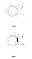
- reference numeral 1 generally indicates a microwave transmitting device (an antenna) and 2 a microwave receiving device.
- these are used to transmit electromagnetic radiation in the microwave regime into a body part (e.g. a head of a human).
- the body part comprise an outer shell structure 4 (a skull) and an internal structure 3 (a brain).
- the microwave radiation is depicted with dashed lines 5.
- a deviation 6 form the normal internal structure is present (e.g. a tumor or a part with a different internal pressure due to aggregation of fluid (e.g. water or blood). This deviation 6 will cause the reflected waves to behave differently than for a structure without such deviation.
- Fig. 2 the skull is illuminated with electromagnetic radiation that is scattered and detected by the receiver 2.
- This figure shows a situation from Fig. 1 with a volume increase inside the skull, the black part 6 representing the location of the swelling 6 of the brain 3.
- the scattered radiation 5 is altered and picked up by the receiver 2.
- Microwave techniques can provide non-invasive, easy access, to the human brain at a relatively low cost. This is accomplished by illuminating the skull with electromagnetic radiation that is propagating through and scattered from the different tissues inside the skull.
- the scattered radiation is carrying the information utilized by this invention for the purpose of detecting and analyzing a possible volume change of the tissue inside the skull and to relate this to an increased ICP (increased intracranial pressure). It will also constitute a method to distinguish between ischemic and hemorrhagic stroke.
- the system constituting the current invention collects a large amount of frequency components in the measurement that is analyzed to extract the necessary information. In this case frequencies in the range from about 100 MHz to about 5 GHz or more can be utilized.
- the system proposed here may be used to monitor traumatic brain injury patients for example by a continuously monitoring bedside system. It would also be possible to extend the method to include monitoring of other parts of the body, e.g. the abdomen in case of suspected internal bleeding. It could also be used as a system, for example in an ambulance, for diagnosis of stroke patients.
- the radiation exerted during the monitoring is of a non damaging type and level and may therefore be used for continuous monitoring of internal parts of the body.
- This system is detecting changes in the brain e.g. caused by brain swelling or bleeding by observing the nature of the scattered radiation.
- the measurements are represented as a multi dimensional vector comprising S-matrix elements at a single frequency or alternatively a large number of frequencies.
- Changes in this vector indicate changes inside the skull and are related to the above mentioned injuries or diseases.
- the monitoring system comprises a transmitter of electromagnetic waves that is placed outside the skull and transmits electromagnetic radiation towards the head. Some portion of the radiation is scattered directly of the skin and some portion is penetrating inside the skull and scattered off the different internal tissues. One or more receivers outside the head are detecting the scattered radiation which is later processed by a monitoring algorithm to detect the pressure increase.
- a schematic sketch of the antenna configuration can be seen in Fig. 1.
- Fig. 1 shows one transmitter irradiating the skull and one receiver picking up the scattered radiation. This is only an example of a system configuration.
- Another configuration of the system may comprise at least one antenna acting both as transmitter and receiver. It could also comprise at least one separate transmitter and at least one separate receiver positioned around the skull.
- Fig. 2 shows the process of volume increase in the brain that is detected by the present invention from its effect on the scattered radiation.
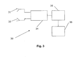
- the antennas transmitting and receiving the microwaves are driven by a signal generator and connected to a receiving unit.
- the analysis of the data is made by the data analysis unit and the result is displayed on a screen, see Fig. 3 .
- the data analysis unit 35 is used for controlling the measurement and analyse the data.
- the data analysis unit is arranged to send a signal to a signal generator, e.g.
- a microwave transceiver 34 which in turn transmit microwave radiation to a transmitting antenna 31 and receives reflected radiation in a receiving antenna 32.
- these two antennas may be combined in one antenna and in such case advantageously a switching mechanism (not shown) is arranged in the path between the antenna and the microwave transceiver inside the transceiver or as an external device.
- the switching mechanism may be used in order to not transmit directly into a receiving unit in the transceiver possibly saturating the input electronics.
- the transceiver may comprise two more or less separate units, a transmitting unit and a receiving unit, or it may be built into one single unit with electronics for each function built into the single unit.
- the data analysis unit 35 is further arranged to control the display unit 36 to show the analysed data.
- Data analysis may be performed at another location by sending (through a network connection or using storage devices) measurement data to an analysis device, e.g. a central server or central computational device for post analysis and/or for storing of measurement data in a central storage facility.
- an analysis device e.g. a central server or central computational device for post analysis and/or for storing of measurement data in a central storage facility.
- the data analysis unit 35, 800 may comprise any suitable type of processing device 801 (as illustrated in Fig. 8 ) such as a microprocessor, ASIC (Application Specific Integrated Circuit), FPGA (Field Programmable Gate Array), or similar. It may further comprise at least one memory 802 of volatile and/or non-volatile type (e.g. RAM, DRAM, hard disk, Flash memory, and so on) and a user interface unit 803. It may further comprise one or several communication or interconnectivity interfaces 804, e.g. network connection(s), keyboard, mouse, serial (e.g.
- the device may further comprise a separate interface 805 to the microwave transceiver 34; however, it should be noted that a transceiver interface may be in some applications through the interconnectivity interface 804.
- the current invention uses a method to compensate for patient movements and extracts the data of interest scattered from inside the skull. For that compensation method it is necessary to make a large number of measurements at different frequencies. The number of measurements could be from at least two up to 1000 or more in a bandwidth within the range 100 MHz - 5 GHz or more.
- the number of measurements could be from at least two up to 1000 or more in a bandwidth within the range 100 MHz - 5 GHz or more.
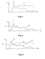
- an inverse Fourier transformation is performed to convert the data into a time domain signal.
- the signal will in principle look similar to what is shown in Fig. 4 .
- the first peak 41 in the reflection data will most likely correspond to the reflection from the outer shell of the body, e.g.
- the solid line 53 is a reference curve (theoretical or measured) which is to be compared to the dotted curve 54 indicating the current status from a new measurement.
- Fig. 6 a sketch of the principal behaviour of the signal is shown due to an increased volume of the brain.
- the first peak 61 represents the reflection at the outer shell and the rest of the signal indicates reflections from internal tissues.
- the solid line 63 is a reference representation (theoretical or measured) and the dotted line 64 is a measurement of the current situation. The difference between these two indicates that changes have occurred in the internal parts of the body. This may be used to determine that a change has occurred and in some applications what type of change and the extent of this change. As measurements are continuously made and analyzed, changes that develop over time can be found and separated from movements of the patient.
- a continuous monitoring of the changes inside the brain can be made. That is, it may be used at a hospital ore some other caring facility for monitoring the development of an ailment under scrutiny; this may be done with a few seconds, minutes or hours interval or even faster or slower depending on the ailments progress over time. It may also be used for monitoring at home, in an ambulance, or in the field (e.g. at a place of an accident or a catastrophe scene).
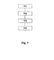
- Fig. 7 illustrates a method according to the present invention, where in a first step 701 at least two measurements are sampled, these are statistically analyzed 702, inversed Fourier transformed into the time domain 703, and compared with reference data 704 in order to determine the current status as compared to reference data (such as from theoretical reference data or a previous measurement of the same body part or a reference body part).
- reference data such as from theoretical reference data or a previous measurement of the same body part or a reference body part.
- the present invention may be realized as a system for the purpose of monitoring intra cranial properties of the brain based on microwave measurements.
- the proposed system uses one or more sources of microwave radiation to illuminate the skull and the same antenna system is used to receive the transmitted signals.
- the system may analyze the data in real time. Changes in the data over time may be used to monitor brain changes. Indications of brain swelling and other changes may be based on continuous measurements and deviations from an initial state of the properties of the brain.
- Circularly polarized radiation may be transmitted and the receivers are capable of receiving elliptically polarized radiation.
- the system may use the orientation of the received polarization and the amplitude and phase information of the received fields in the data analysis.
- the present invention may also be realized as a method to detect patient movements and compensate for that in order not to corrupt the data with movement artefacts.
- the present invention also a compensation scheme that is based on an inverse Fourier transform of the measured data into time domain.
- the analysis is based on the first reflection that comes from the skin. If the head is moved the first reflection will move correspondingly and thus the movement of the head can be monitored through the movement of the first reflection.
- a monitoring algorithm is provided that is based on the time domain data following after the first reflection from the skin. This measured scattering data comes from inside the skull and are used by the monitoring algorithm to detect the swelling.
- the monitoring algorithm where the measured data may be expressed as in equation (1) and changes in this representation is related to different injuries or diseases.
- the monitoring algorithm may use the movement detection scheme for the purpose of excluding the data measured when the patient is moving from the analysis.
- the system may also be used to detect abnormalities in other parts of the body than in the skull. This application includes, but is not limited to, detecting internal bleeding in the abdomen.
- the system may be used to diagnose between ischemic and hemorrhagic stroke.
- the scattered radiation is carrying the information utilized by this invention for the purpose of detecting and analyzing a possible dislocation of surgically implanted hip-joint prosthesis.
- the analysis could be based on the electromagnetic radiation scattered from the prosthesis between different occasions of examination and comparison with a measurement when the prosthesis is known to be in place.
- the measurement for comparison could for instance be made immediately after the surgery.
- microwave measurements of the scattering are compared to the measurement made with the prosthesis in place.
- a deviation between the two measurements can be used as an indicator that something has happened to the prosthesis, on the other hand if the radiation patterns are the same it can be concluded that the prosthesis has not moved.
- the hip region is radiated with circularly polarized microwave radiation at a frequency that corresponds to the resonance frequency of the prosthesis. This should occur when the wavelength of the radiation is similar to or close to the length of the prosthesis.
- elliptically reflected radiation could be measured at a number of positions outside the body.
- the orientation of the elliptical radiation bears information of the orientation of the prosthesis. In a similar way as described above comparison can now be made to a case measured when the prosthesis is known to be in place.
- the reference system could consist of implanted non-linear elements that have the effect of changing the frequency of the incoming radiation, RF-id tags might also be a possibility here.
- the reference system could consist of implanted non-linear elements that have the effect of changing the frequency of the incoming radiation, RF-id tags might also be a possibility here.
- the scattering from the prosthesis may be related to the reference system when determining its location or possible dislocation. Once that is made the processing of the scattering data from the prosthesis can be made.
- the measurement equipment in this case therefore needs to be capable of transmitting one frequency component and receiving another.
- the current invention also contains a solution using the hip prosthesis as a radiating structure.
- the prosthesis is usually manufactured using materials such as titanium.
- a novel transceiver implant inside the prosthesis and a minor modification to the prosthesis the structure can be used as a radiating element. It is shown that this implanted radiating structure inside the human body will have a very distinct radiation pattern. Using this radiation pattern one can decide whether the structure has moved inside the human body. The patient can be scanned for the near field radiation pattern immediately after surgery. The radiation pattern is recorded and can be compared to later scans for finding abnormalities in a similar way as described above.
- the device may be continuously worn at the hip joint and intermittently measure the condition of the joint and provide an alarm if the condition is outside a predetermined setting.
- the solution according to the present invention opens for a wearable t least portable monitoring device which may be used for home monitoring of body part to be monitored. This may be convenient for instance for monitoring stroke patients after treatment in hospital in a home or care environment.
Landscapes
- Health & Medical Sciences (AREA)
- Life Sciences & Earth Sciences (AREA)
- Biomedical Technology (AREA)
- Veterinary Medicine (AREA)
- Public Health (AREA)
- General Health & Medical Sciences (AREA)
- Animal Behavior & Ethology (AREA)
- Heart & Thoracic Surgery (AREA)
- Engineering & Computer Science (AREA)
- Biophysics (AREA)
- Surgery (AREA)
- Physics & Mathematics (AREA)
- Medical Informatics (AREA)
- Molecular Biology (AREA)
- Nuclear Medicine, Radiotherapy & Molecular Imaging (AREA)
- Pathology (AREA)
- Transplantation (AREA)
- Orthopedic Medicine & Surgery (AREA)
- Neurology (AREA)
- Radiology & Medical Imaging (AREA)
- Vascular Medicine (AREA)
- Cardiology (AREA)
- Oral & Maxillofacial Surgery (AREA)
- Physical Education & Sports Medicine (AREA)
- Physiology (AREA)
- Neurosurgery (AREA)
- Measurement And Recording Of Electrical Phenomena And Electrical Characteristics Of The Living Body (AREA)
- Measuring And Recording Apparatus For Diagnosis (AREA)
Claims (16)
- Dispositif (35, 800) pour obtenir une représentation de l'état de parties internes d'une partie de corps, comprenanta. une unité de traitement (801) ;b. une interface (805) vers un émetteur-récepteur hyperfréquence ;c. une unité d'affichage (36) ;
dans lequel l'unité de traitement (801) est agencée pour :envoyer de manière répétée un signal de commande vers l'émetteur-récepteur hyperfréquence (34) pour générer une impulsion de rayonnements hyperfréquences destinés à être transmis depuis au moins une antenne (31) dans la partie de corps ;recevoir des signaux indiquant qu'un rayonnement hyperfréquence est reçu de l'émetteur-récepteur hyperfréquence (34) ;analyser les signaux reçus selon le temps et l'amplitude ;éliminer les données concernant le mouvement du corps, comparer les signaux analysés à des données de référence théoriques ou mesurées et mesurer et analyser en continu des signaux de changements survenus au cours du temps séparés des mouvements du corps ;déterminer l'état de la partie interne du corps à partir de cette comparaison ;caractérisé en ce quel'unité de traitement (801) est agencée pour baser l'élimination sur une transformée de Fourier inverse des données mesurées dans le domaine temporel et utiliser la première réflexion comme une indication de mouvement. - Dispositif (35, 800) selon la revendication 1, dans lequel le dispositif (35,800) est agencé pour analyser les signaux par rapport à un cerveau.
- Dispositif (35, 800) selon la revendication 1, dans lequel le dispositif (35, 800) est agencé pour analyser les signaux par rapport à une articulation de hanche.
- Dispositif (35, 800) selon la revendication 1, dans lequel le dispositif (35, 800) est agencé pour analyser les signaux par rapport à des mesures initiales de la partie interne du corps.
- Dispositif (35, 800) selon la revendication 1, dans lequel le dispositif (35, 800) est agencé pour surveiller en continu l'état d'une partie interne du corps.
- Dispositif (35, 800) selon la revendication 1, dans lequel l'unité de traitement (801) est agencée pour utiliser les informations concernant la polarisation, l'amplitude, et
la phase dans l'analyse. - Procédé pour obtenir une représentation de l'état de parties internes d'un corps, comprenant les étapes consistant àa. envoyer de manière répétée un signal de commande d'une unité de traitement (801) vers un émetteur-récepteur hyperfréquence (34) ;b. recevoir un signal indiquant que des signaux hyperfréquences ont été reçus de l'émetteur-récepteur hyperfréquence (34) ;c. analyser les signaux reçus selon le temps et l'amplitude ;d. éliminer les données concernant le mouvement du corps ;e. comparer les signaux analysés à des données de référence théoriques ou mesurées et mesurer et analyser en continu des signaux de changements survenus au cours du temps séparés des mouvements du corps ;f. déterminer l'état des parties internes du corps en utilisant la comparaison d'une manière continue ;
caractérisé en ce que
l'unité de traitement (801) est agencée pour baser l'élimination sur une transformée de Fourier inverse des données mesurées dans le domaine temporel et utiliser la première réflexion comme une indication de mouvement. - Système pour obtenir une représentation de l'état de parties internes d'un corps, comprenant :a. le dispositif (35, 800) selon l'une quelconque des revendications 1 à 6 ;b. au moins une antenne d'émission (31) dans les hyperfréquences ; etc. au moins une antenne de réception (32) dans les hyperfréquences.
- Système selon la revendication 8, comprenant une antenne d'émission et de réception combinée.
- Système selon la revendication 8, comprenant une pluralité d'antennes agencées selon un motif entourant au moins partiellement la partie de corps.
- Système selon l'une quelconque des revendications 8 à 10, dans lequel l'antenne d'émission (31) est agencée pour émettre un rayonnement polarisé de manière circulaire et l'antenne de réception (32) est agencée pour recevoir au moins un rayonnement polarisé de manière elliptique.
- Système selon la revendication 8, dans lequel l'unité de traitement (801) est agencée pour surveiller en continu l'état d'un cerveau.
- Système selon la revendication 8, dans lequel l'unité de traitement (801) est agencée pour détecter des changements volumétriques ou de pression concernant le cerveau.
- Système selon la revendication 8, dans lequel l'unité de traitement (801) est agencée pour surveiller une partie interne du corps sur une base temporelle continue.
- Système selon la revendication 8, étant agencé sous forme d'une unité à porter.
- Système selon la revendication 8, où l'unité de traitement (801) est agencée pour déterminer un vecteur de position d'une pluralité de vecteurs s :

pour un système comprenant un nombre n d'antennes et un nombre m de fréquences.
Priority Applications (1)
| Application Number | Priority Date | Filing Date | Title |
|---|---|---|---|
| PL07748306T PL2032030T3 (pl) | 2006-06-29 | 2007-06-29 | Rozwiązanie dla wewnętrznego monitorowania ciała |
Applications Claiming Priority (2)
| Application Number | Priority Date | Filing Date | Title |
|---|---|---|---|
| US80610506P | 2006-06-29 | 2006-06-29 | |
| PCT/SE2007/000647 WO2008002251A1 (fr) | 2006-06-29 | 2007-06-29 | Solution pour la surveillance interne du corps |
Publications (3)
| Publication Number | Publication Date |
|---|---|
| EP2032030A1 EP2032030A1 (fr) | 2009-03-11 |
| EP2032030A4 EP2032030A4 (fr) | 2009-12-02 |
| EP2032030B1 true EP2032030B1 (fr) | 2014-08-06 |
Family
ID=38845896
Family Applications (1)
| Application Number | Title | Priority Date | Filing Date |
|---|---|---|---|
| EP07748306.3A Active EP2032030B1 (fr) | 2006-06-29 | 2007-06-29 | Solution pour la surveillance interne du corps |
Country Status (5)
| Country | Link |
|---|---|
| US (1) | US9332922B2 (fr) |
| EP (1) | EP2032030B1 (fr) |
| ES (1) | ES2496148T3 (fr) |
| PL (1) | PL2032030T3 (fr) |
| WO (1) | WO2008002251A1 (fr) |
Cited By (3)
| Publication number | Priority date | Publication date | Assignee | Title |
|---|---|---|---|---|
| WO2018104300A1 (fr) | 2016-12-06 | 2018-06-14 | Medfield Diagnostics Ab | Système et procédé de détection d'un objet interne positionné asymétriquement dans un corps |
| WO2018127434A1 (fr) | 2017-01-09 | 2018-07-12 | Medfield Diagnostics Ab | Procédé et système pour assurer un contact d'antenne et une fonction système dans les applications de détection des propriétés diélectriques internes dans le corps |
| WO2021249881A1 (fr) | 2020-06-09 | 2021-12-16 | Medfield Diagnostics Ab | Classification de données de diffusion par radiofréquence |
Families Citing this family (19)
| Publication number | Priority date | Publication date | Assignee | Title |
|---|---|---|---|---|
| US7047058B1 (en) | 2001-02-06 | 2006-05-16 | Medrad, Inc. | Apparatuses, systems and methods for extravasation detection |
| EP2194871B1 (fr) | 2007-09-05 | 2016-08-17 | Sensible Medical Innovations Ltd. | Procédé et système pour contrôler un fluide de tissu thoracique |
| KR101003509B1 (ko) * | 2008-07-11 | 2010-12-30 | 한국전자통신연구원 | 전자파 특성을 이용한 인체 암 진단 장치 및 방법 |
| US10667715B2 (en) | 2008-08-20 | 2020-06-02 | Sensible Medical Innovations Ltd. | Methods and devices of cardiac tissue monitoring and analysis |
| ES2637021T3 (es) * | 2009-03-04 | 2017-10-10 | Sensible Medical Innovations Ltd. | Sistema para monitorizar tejidos intracorporales |
| US9724010B2 (en) | 2010-07-08 | 2017-08-08 | Emtensor Gmbh | Systems and methods of 4D electromagnetic tomographic (EMT) differential (dynamic) fused imaging |
| WO2013033162A1 (fr) | 2011-09-02 | 2013-03-07 | Battelle Memorial Institute | Système de détection d'extravasation répartie |
| US9414749B2 (en) | 2012-11-21 | 2016-08-16 | Emtensor Gmbh | Electromagnetic tomography solutions for scanning head |
| US20140275944A1 (en) | 2013-03-15 | 2014-09-18 | Emtensor Gmbh | Handheld electromagnetic field-based bio-sensing and bio-imaging system |
| US9072449B2 (en) | 2013-03-15 | 2015-07-07 | Emtensor Gmbh | Wearable/man-portable electromagnetic tomographic imaging |
| GB2527748A (en) * | 2014-06-20 | 2016-01-06 | Safeetechnologies As | Monitoring the body using microwaves |
| JP6271384B2 (ja) * | 2014-09-19 | 2018-01-31 | 株式会社東芝 | 検査装置 |
| DK3361955T3 (da) | 2015-10-16 | 2020-10-26 | Emtensor Gmbh | Elektromagnetisk interferensmønstergenkendelsestomografi |
| CN105816172B (zh) * | 2016-03-11 | 2018-09-14 | 金陵科技学院 | 一种脑肿瘤微波检测系统 |
| CN105832331B (zh) * | 2016-03-18 | 2019-04-30 | 中国人民解放军第三军医大学 | 基于宽带天线技术的非接触脑出血检测装置及其检测方法 |
| WO2018098387A1 (fr) | 2016-11-23 | 2018-05-31 | Emtensor Gmbh | Utilisation d'un champ électromagnétique destiné à une imagerie tomographique d'une tête |
| CN108577837A (zh) * | 2018-05-17 | 2018-09-28 | 金陵科技学院 | 一种基于uwb源的便携式肿瘤检测装置及检测方法 |
| US20210218149A1 (en) | 2018-05-23 | 2021-07-15 | Medfield Diagnostics Ab | Solution For Absorption Of Microwaves |
| CN115804582A (zh) * | 2022-12-01 | 2023-03-17 | 北京大学第三医院(北京大学第三临床医学院) | 基于人工智能技术的微波无创颅内压连续监测系统和用途 |
Citations (1)
| Publication number | Priority date | Publication date | Assignee | Title |
|---|---|---|---|---|
| US20030088180A1 (en) * | 2001-07-06 | 2003-05-08 | Van Veen Barry D. | Space-time microwave imaging for cancer detection |
Family Cites Families (11)
| Publication number | Priority date | Publication date | Assignee | Title |
|---|---|---|---|---|
| US3721900A (en) * | 1971-04-15 | 1973-03-20 | Gen Electric | Microwave detection instrument and antenna therefor |
| DE69532367T2 (de) * | 1994-07-01 | 2004-10-21 | Interstitial Llc | Nachweis und Darstellung von Brustkrebs durch elektromagnetische Millimeterwellen |
| US5829437A (en) * | 1994-07-01 | 1998-11-03 | Interstitial, Inc. | Microwave method and system to detect and locate cancers in heterogenous tissues |
| USD454670S1 (en) * | 1997-04-24 | 2002-03-19 | Rose Weller | Animal leash |
| US6064903A (en) * | 1997-12-29 | 2000-05-16 | Spectra Research, Inc. | Electromagnetic detection of an embedded dielectric region within an ambient dielectric region |
| US6233479B1 (en) | 1998-09-15 | 2001-05-15 | The Regents Of The University Of California | Microwave hematoma detector |
| US6454711B1 (en) * | 1999-04-23 | 2002-09-24 | The Regents Of The University Of California | Microwave hemorrhagic stroke detector |
| EP1834667B1 (fr) * | 2001-07-26 | 2017-08-23 | Bayer Healthcare LLC | Capteurs électromagnétiques destinés à des applications sur des tissus biologiques |
| WO2003009753A2 (fr) * | 2001-07-26 | 2003-02-06 | Chad Bouton | Detection de fluides dans des tissus |
| US20040249257A1 (en) * | 2003-06-04 | 2004-12-09 | Tupin Joe Paul | Article of manufacture for extracting physiological data using ultra-wideband radar and improved signal processing techniques |
| US20070293752A1 (en) | 2004-09-10 | 2007-12-20 | Industrial Research Limited | Synthetic Focusing Method |
-
2007
- 2007-06-29 PL PL07748306T patent/PL2032030T3/pl unknown
- 2007-06-29 ES ES07748306.3T patent/ES2496148T3/es active Active
- 2007-06-29 US US12/306,823 patent/US9332922B2/en active Active
- 2007-06-29 WO PCT/SE2007/000647 patent/WO2008002251A1/fr active Application Filing
- 2007-06-29 EP EP07748306.3A patent/EP2032030B1/fr active Active
Patent Citations (1)
| Publication number | Priority date | Publication date | Assignee | Title |
|---|---|---|---|---|
| US20030088180A1 (en) * | 2001-07-06 | 2003-05-08 | Van Veen Barry D. | Space-time microwave imaging for cancer detection |
Cited By (3)
| Publication number | Priority date | Publication date | Assignee | Title |
|---|---|---|---|---|
| WO2018104300A1 (fr) | 2016-12-06 | 2018-06-14 | Medfield Diagnostics Ab | Système et procédé de détection d'un objet interne positionné asymétriquement dans un corps |
| WO2018127434A1 (fr) | 2017-01-09 | 2018-07-12 | Medfield Diagnostics Ab | Procédé et système pour assurer un contact d'antenne et une fonction système dans les applications de détection des propriétés diélectriques internes dans le corps |
| WO2021249881A1 (fr) | 2020-06-09 | 2021-12-16 | Medfield Diagnostics Ab | Classification de données de diffusion par radiofréquence |
Also Published As
| Publication number | Publication date |
|---|---|
| US9332922B2 (en) | 2016-05-10 |
| EP2032030A4 (fr) | 2009-12-02 |
| PL2032030T3 (pl) | 2015-01-30 |
| EP2032030A1 (fr) | 2009-03-11 |
| ES2496148T3 (es) | 2014-09-18 |
| WO2008002251A1 (fr) | 2008-01-03 |
| US20100174179A1 (en) | 2010-07-08 |
Similar Documents
| Publication | Publication Date | Title |
|---|---|---|
| EP2032030B1 (fr) | Solution pour la surveillance interne du corps | |
| US10506943B2 (en) | Methods and systems for monitoring intrabody tissues | |
| US11857305B2 (en) | System and method for detecting an assymetrically positioned internal object in a body | |
| Garcia-Pardo et al. | Ultrawideband technology for medical in-body sensor networks: An overview of the human body as a propagation medium, phantoms, and approaches for propagation analysis | |
| KR101307514B1 (ko) | 마이크로파 영상 복원 장치 | |
| JP2010512190A (ja) | 哺乳類有機体中のクローズド・ループ・コントロールを用いた組織の内容及び/又は構造の変化の検知用プラットフォーム | |
| CN109199381B (zh) | 一种全息微波弹性成像系统及其成像方法 | |
| WO2018127434A1 (fr) | Procédé et système pour assurer un contact d'antenne et une fonction système dans les applications de détection des propriétés diélectriques internes dans le corps | |
| EP3556278A1 (fr) | Dispositif de balayage pour objets vivants | |
| Porter et al. | Microwave-based detection of the bladder state as a support tool for urinary incontinence [bioelectromagnetics] | |
| Särestöniemi et al. | Remote diagnostics and monitoring using microwave technique: improving healthcare in rural areas and in exceptional situations | |
| Savazzi et al. | Numerical assessment of microwave imaging for axillary lymph nodes screening using anthropomorphic phantom | |
| Singh et al. | A review of electromagnetic sensing for healthcare applications | |
| Shah et al. | Penetration depth evaluation of split ring resonator sensor using in-vivo microwave reflectivity and ultrasound measurements | |
| Hilger et al. | Could we use UWB sensing for breast cancer detection? | |
| Santos et al. | A study on the sensitivity of microwave imaging for detecting small-width bone fractures | |
| US20210259570A1 (en) | Systems and methods for assessing a physiological property of a biological tissue based on its microwave transmission properties | |
| Cheng et al. | 3-D microwave imaging for breast cancer | |
| Al Muqatash et al. | Detection of the cervical spondylotic myelopathy using noninvasive microwave imaging technique | |
| JP2022509376A (ja) | ヒト組織内の生体変化の認識のためのシステム | |
| Mirza | Ultra-Wideband Imaging System For Medical Applications. Simulation models and Experimental Investigations for Early Breast Cancer & Bone Fracture Detection Using UWB Microwave Sensors | |
| WO2022217311A1 (fr) | Appareil et procédé de détection médicale | |
| Taylor | Medical Applications of Ultrawideband Radar | |
| Pollacco | Microwave medical imaging | |
| Lenzi | A Non-Invasive Radar Technique Based on Artificial Neural Network for Breast Cancer Detection |
Legal Events
| Date | Code | Title | Description |
|---|---|---|---|
| PUAI | Public reference made under article 153(3) epc to a published international application that has entered the european phase |
Free format text: ORIGINAL CODE: 0009012 |
|
| 17P | Request for examination filed |
Effective date: 20090114 |
|
| AK | Designated contracting states |
Kind code of ref document: A1 Designated state(s): AT BE BG CH CY CZ DE DK EE ES FI FR GB GR HU IE IS IT LI LT LU LV MC MT NL PL PT RO SE SI SK TR |
|
| AX | Request for extension of the european patent |
Extension state: AL BA HR MK RS |
|
| RIN1 | Information on inventor provided before grant (corrected) |
Inventor name: HASHEMZADEH, PARHAM Inventor name: FHAGER, ANDREAS Inventor name: PERSSON, MIKAEL |
|
| A4 | Supplementary search report drawn up and despatched |
Effective date: 20091029 |
|
| RIC1 | Information provided on ipc code assigned before grant |
Ipc: A61B 5/05 20060101AFI20080307BHEP |
|
| 17Q | First examination report despatched |
Effective date: 20100218 |
|
| DAX | Request for extension of the european patent (deleted) | ||
| GRAJ | Information related to disapproval of communication of intention to grant by the applicant or resumption of examination proceedings by the epo deleted |
Free format text: ORIGINAL CODE: EPIDOSDIGR1 |
|
| GRAP | Despatch of communication of intention to grant a patent |
Free format text: ORIGINAL CODE: EPIDOSNIGR1 |
|
| INTG | Intention to grant announced |
Effective date: 20140403 |
|
| GRAS | Grant fee paid |
Free format text: ORIGINAL CODE: EPIDOSNIGR3 |
|
| GRAA | (expected) grant |
Free format text: ORIGINAL CODE: 0009210 |
|
| AK | Designated contracting states |
Kind code of ref document: B1 Designated state(s): AT BE BG CH CY CZ DE DK EE ES FI FR GB GR HU IE IS IT LI LT LU LV MC MT NL PL PT RO SE SI SK TR |
|
| REG | Reference to a national code |
Ref country code: GB Ref legal event code: FG4D |
|
| REG | Reference to a national code |
Ref country code: AT Ref legal event code: REF Ref document number: 680595 Country of ref document: AT Kind code of ref document: T Effective date: 20140815 Ref country code: CH Ref legal event code: EP |
|
| REG | Reference to a national code |
Ref country code: IE Ref legal event code: FG4D |
|
| REG | Reference to a national code |
Ref country code: DE Ref legal event code: R096 Ref document number: 602007037985 Country of ref document: DE Effective date: 20140918 Ref country code: ES Ref legal event code: FG2A Ref document number: 2496148 Country of ref document: ES Kind code of ref document: T3 Effective date: 20140918 |
|
| REG | Reference to a national code |
Ref country code: SE Ref legal event code: TRGR |
|
| REG | Reference to a national code |
Ref country code: NL Ref legal event code: VDEP Effective date: 20140806 |
|
| REG | Reference to a national code |
Ref country code: LT Ref legal event code: MG4D |
|
| PG25 | Lapsed in a contracting state [announced via postgrant information from national office to epo] |
Ref country code: FI Free format text: LAPSE BECAUSE OF FAILURE TO SUBMIT A TRANSLATION OF THE DESCRIPTION OR TO PAY THE FEE WITHIN THE PRESCRIBED TIME-LIMIT Effective date: 20140806 Ref country code: BG Free format text: LAPSE BECAUSE OF FAILURE TO SUBMIT A TRANSLATION OF THE DESCRIPTION OR TO PAY THE FEE WITHIN THE PRESCRIBED TIME-LIMIT Effective date: 20141106 Ref country code: LT Free format text: LAPSE BECAUSE OF FAILURE TO SUBMIT A TRANSLATION OF THE DESCRIPTION OR TO PAY THE FEE WITHIN THE PRESCRIBED TIME-LIMIT Effective date: 20140806 Ref country code: GR Free format text: LAPSE BECAUSE OF FAILURE TO SUBMIT A TRANSLATION OF THE DESCRIPTION OR TO PAY THE FEE WITHIN THE PRESCRIBED TIME-LIMIT Effective date: 20141107 Ref country code: PT Free format text: LAPSE BECAUSE OF FAILURE TO SUBMIT A TRANSLATION OF THE DESCRIPTION OR TO PAY THE FEE WITHIN THE PRESCRIBED TIME-LIMIT Effective date: 20141209 |
|
| REG | Reference to a national code |
Ref country code: PL Ref legal event code: T3 |
|
| PG25 | Lapsed in a contracting state [announced via postgrant information from national office to epo] |
Ref country code: LV Free format text: LAPSE BECAUSE OF FAILURE TO SUBMIT A TRANSLATION OF THE DESCRIPTION OR TO PAY THE FEE WITHIN THE PRESCRIBED TIME-LIMIT Effective date: 20140806 Ref country code: CY Free format text: LAPSE BECAUSE OF FAILURE TO SUBMIT A TRANSLATION OF THE DESCRIPTION OR TO PAY THE FEE WITHIN THE PRESCRIBED TIME-LIMIT Effective date: 20140806 Ref country code: IS Free format text: LAPSE BECAUSE OF FAILURE TO SUBMIT A TRANSLATION OF THE DESCRIPTION OR TO PAY THE FEE WITHIN THE PRESCRIBED TIME-LIMIT Effective date: 20141206 Ref country code: NL Free format text: LAPSE BECAUSE OF FAILURE TO SUBMIT A TRANSLATION OF THE DESCRIPTION OR TO PAY THE FEE WITHIN THE PRESCRIBED TIME-LIMIT Effective date: 20140806 |
|
| PG25 | Lapsed in a contracting state [announced via postgrant information from national office to epo] |
Ref country code: EE Free format text: LAPSE BECAUSE OF FAILURE TO SUBMIT A TRANSLATION OF THE DESCRIPTION OR TO PAY THE FEE WITHIN THE PRESCRIBED TIME-LIMIT Effective date: 20140806 Ref country code: SK Free format text: LAPSE BECAUSE OF FAILURE TO SUBMIT A TRANSLATION OF THE DESCRIPTION OR TO PAY THE FEE WITHIN THE PRESCRIBED TIME-LIMIT Effective date: 20140806 Ref country code: RO Free format text: LAPSE BECAUSE OF FAILURE TO SUBMIT A TRANSLATION OF THE DESCRIPTION OR TO PAY THE FEE WITHIN THE PRESCRIBED TIME-LIMIT Effective date: 20140806 Ref country code: DK Free format text: LAPSE BECAUSE OF FAILURE TO SUBMIT A TRANSLATION OF THE DESCRIPTION OR TO PAY THE FEE WITHIN THE PRESCRIBED TIME-LIMIT Effective date: 20140806 Ref country code: CZ Free format text: LAPSE BECAUSE OF FAILURE TO SUBMIT A TRANSLATION OF THE DESCRIPTION OR TO PAY THE FEE WITHIN THE PRESCRIBED TIME-LIMIT Effective date: 20140806 |
|
| REG | Reference to a national code |
Ref country code: DE Ref legal event code: R097 Ref document number: 602007037985 Country of ref document: DE |
|
| PLBE | No opposition filed within time limit |
Free format text: ORIGINAL CODE: 0009261 |
|
| STAA | Information on the status of an ep patent application or granted ep patent |
Free format text: STATUS: NO OPPOSITION FILED WITHIN TIME LIMIT |
|
| REG | Reference to a national code |
Ref country code: FR Ref legal event code: PLFP Year of fee payment: 9 |
|
| 26N | No opposition filed |
Effective date: 20150507 |
|
| PG25 | Lapsed in a contracting state [announced via postgrant information from national office to epo] |
Ref country code: SI Free format text: LAPSE BECAUSE OF FAILURE TO SUBMIT A TRANSLATION OF THE DESCRIPTION OR TO PAY THE FEE WITHIN THE PRESCRIBED TIME-LIMIT Effective date: 20140806 |
|
| PG25 | Lapsed in a contracting state [announced via postgrant information from national office to epo] |
Ref country code: MC Free format text: LAPSE BECAUSE OF FAILURE TO SUBMIT A TRANSLATION OF THE DESCRIPTION OR TO PAY THE FEE WITHIN THE PRESCRIBED TIME-LIMIT Effective date: 20140806 |
|
| REG | Reference to a national code |
Ref country code: CH Ref legal event code: PL |
|
| PG25 | Lapsed in a contracting state [announced via postgrant information from national office to epo] |
Ref country code: LU Free format text: LAPSE BECAUSE OF FAILURE TO SUBMIT A TRANSLATION OF THE DESCRIPTION OR TO PAY THE FEE WITHIN THE PRESCRIBED TIME-LIMIT Effective date: 20150629 |
|
| REG | Reference to a national code |
Ref country code: IE Ref legal event code: MM4A |
|
| PG25 | Lapsed in a contracting state [announced via postgrant information from national office to epo] |
Ref country code: LI Free format text: LAPSE BECAUSE OF NON-PAYMENT OF DUE FEES Effective date: 20150630 Ref country code: CH Free format text: LAPSE BECAUSE OF NON-PAYMENT OF DUE FEES Effective date: 20150630 Ref country code: IE Free format text: LAPSE BECAUSE OF NON-PAYMENT OF DUE FEES Effective date: 20150629 |
|
| REG | Reference to a national code |
Ref country code: FR Ref legal event code: PLFP Year of fee payment: 10 |
|
| PG25 | Lapsed in a contracting state [announced via postgrant information from national office to epo] |
Ref country code: BE Free format text: LAPSE BECAUSE OF FAILURE TO SUBMIT A TRANSLATION OF THE DESCRIPTION OR TO PAY THE FEE WITHIN THE PRESCRIBED TIME-LIMIT Effective date: 20140806 |
|
| PG25 | Lapsed in a contracting state [announced via postgrant information from national office to epo] |
Ref country code: MT Free format text: LAPSE BECAUSE OF FAILURE TO SUBMIT A TRANSLATION OF THE DESCRIPTION OR TO PAY THE FEE WITHIN THE PRESCRIBED TIME-LIMIT Effective date: 20140806 |
|
| PG25 | Lapsed in a contracting state [announced via postgrant information from national office to epo] |
Ref country code: HU Free format text: LAPSE BECAUSE OF FAILURE TO SUBMIT A TRANSLATION OF THE DESCRIPTION OR TO PAY THE FEE WITHIN THE PRESCRIBED TIME-LIMIT; INVALID AB INITIO Effective date: 20070629 |
|
| REG | Reference to a national code |
Ref country code: FR Ref legal event code: PLFP Year of fee payment: 11 |
|
| PG25 | Lapsed in a contracting state [announced via postgrant information from national office to epo] |
Ref country code: TR Free format text: LAPSE BECAUSE OF FAILURE TO SUBMIT A TRANSLATION OF THE DESCRIPTION OR TO PAY THE FEE WITHIN THE PRESCRIBED TIME-LIMIT Effective date: 20140806 |
|
| REG | Reference to a national code |
Ref country code: FR Ref legal event code: PLFP Year of fee payment: 12 |
|
| PGFP | Annual fee paid to national office [announced via postgrant information from national office to epo] |
Ref country code: PL Payment date: 20190612 Year of fee payment: 13 Ref country code: IT Payment date: 20190614 Year of fee payment: 13 |
|
| PG25 | Lapsed in a contracting state [announced via postgrant information from national office to epo] |
Ref country code: IT Free format text: LAPSE BECAUSE OF NON-PAYMENT OF DUE FEES Effective date: 20200629 |
|
| REG | Reference to a national code |
Ref country code: ES Ref legal event code: FD2A Effective date: 20211126 |
|
| PG25 | Lapsed in a contracting state [announced via postgrant information from national office to epo] |
Ref country code: ES Free format text: LAPSE BECAUSE OF NON-PAYMENT OF DUE FEES Effective date: 20200630 |
|
| PG25 | Lapsed in a contracting state [announced via postgrant information from national office to epo] |
Ref country code: PL Free format text: LAPSE BECAUSE OF NON-PAYMENT OF DUE FEES Effective date: 20200629 |
|
| PGFP | Annual fee paid to national office [announced via postgrant information from national office to epo] |
Ref country code: FR Payment date: 20230627 Year of fee payment: 17 Ref country code: DE Payment date: 20230612 Year of fee payment: 17 |
|
| PGFP | Annual fee paid to national office [announced via postgrant information from national office to epo] |
Ref country code: SE Payment date: 20230620 Year of fee payment: 17 Ref country code: AT Payment date: 20230615 Year of fee payment: 17 |
|
| PGFP | Annual fee paid to national office [announced via postgrant information from national office to epo] |
Ref country code: GB Payment date: 20230613 Year of fee payment: 17 |