EP2031462A2 - Image forming apparatus - Google Patents
Image forming apparatus Download PDFInfo
- Publication number
- EP2031462A2 EP2031462A2 EP08015034A EP08015034A EP2031462A2 EP 2031462 A2 EP2031462 A2 EP 2031462A2 EP 08015034 A EP08015034 A EP 08015034A EP 08015034 A EP08015034 A EP 08015034A EP 2031462 A2 EP2031462 A2 EP 2031462A2
- Authority
- EP
- European Patent Office
- Prior art keywords
- rotation unit
- pressure
- fixing
- side rotation
- temperature
- Prior art date
- Legal status (The legal status is an assumption and is not a legal conclusion. Google has not performed a legal analysis and makes no representation as to the accuracy of the status listed.)
- Withdrawn
Links
Images


Classifications
-
- G—PHYSICS
- G03—PHOTOGRAPHY; CINEMATOGRAPHY; ANALOGOUS TECHNIQUES USING WAVES OTHER THAN OPTICAL WAVES; ELECTROGRAPHY; HOLOGRAPHY
- G03G—ELECTROGRAPHY; ELECTROPHOTOGRAPHY; MAGNETOGRAPHY
- G03G15/00—Apparatus for electrographic processes using a charge pattern
- G03G15/20—Apparatus for electrographic processes using a charge pattern for fixing, e.g. by using heat
- G03G15/2003—Apparatus for electrographic processes using a charge pattern for fixing, e.g. by using heat using heat
- G03G15/2014—Apparatus for electrographic processes using a charge pattern for fixing, e.g. by using heat using heat using contact heat
- G03G15/2039—Apparatus for electrographic processes using a charge pattern for fixing, e.g. by using heat using heat using contact heat with means for controlling the fixing temperature
Definitions
- the present invention relates to an image forming apparatus such as an electrophotographic copying machine or printer.
- the conventional image forming apparatus has both a monochrome mode and a color mode, in general. However, in most cases, the monochrome mode is used by users.
- An object of the present invention is to provide an image forming apparatus which can reduce the warm-up time and can thereby reduce waiting time of users using in the monochrome mode.
- a one aspect of the present invention provides an image forming apparatus having a fixing-side rotation unit, a fixing-side heating section which heats the fixing-side rotation unit, a pressure-side rotation unit which contacts the fixing-side rotation unit to form a nip section, a first temperature sensor which detects temperature of the fixing-side rotation unit, a second temperature sensor which detects temperature of the pressure-side rotation unit, and a warm-up operation control section which performs warm-up operation of the fixing-side rotation unit and the pressure-side rotation unit from start-up until temperature of the fixing-side rotation unit exceeds a first specified value based on an output of the first temperature sensor in a case of forming a monochrome image, and which performs warm-up operation of the fixing-side rotation unit and the pressure-side rotation unit from start-up until temperature of the pressure-side rotation unit exceeds a second specified value based on an output of the second temperature sensor in a case of forming a color image, wherein time required for
- the monochrome image refers to an image in which one layer of toner is formed on a recording material.
- the color image refers to an image in which a plurality of layers (e.g., 2 to 3 layers) of toner is formed on a recording material.
- the image forming apparatus has the warm-up operation control section wherein time required for the temperature of the fixing-side rotation unit to exceed the first specified value is set shorter than time required for temperature of the pressure-side rotation unit to exceed the second specified value.
- the warm-up time in the monochrome mode can be reduced, and thereby the waiting time of the users using the monochrome mode can be reduced.
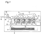
- An image forming apparatus in one embodiment of the present invention is a color printer having image forming units 1, as shown in Fig. 1 .
- the image forming units 1 respectively form color toner images of black (BK), yellow (Y), magenta (M) and cyan (C).
- the image forming units 1 for BK, Y, M, and C are respectively placed in this order from an upper stream side of an intermediate transfer belt 11 along this belt 11 which rotates in the direction of an arrow "A".
- the image forming unit 1 has a photoconductor drum 2, a charging section 3 for uniformly charging the photoconductor drum 2, an exposure section 9 for performing image exposure of the charged photoconductor drum 2, and a developing section 4 for developing an electrostatic latent image formed by the exposure with use of the toner of each color.
- the developed toner image is primarily transferred to the intermediate transfer belt 11 by a primary transfer section 12. After the primary transfer, the toner remaining on the photoconductor drum 2 is removed by a cleaning section 5 placed downstream. Then, the toner is withdrawn from the lower side of the cleaning section 5.
- the toner image developed on the photoconductor drum 2 is transferred onto the intermediate transfer belt 11 by the primary transfer section 12 at a contact position with the intermediate transfer belt 11. Every time the intermediate transfer belt 11 passes each of the image forming units 1, a toner image is surprinted on the intermediate transfer belt 11, resulting in that a full color toner images are formed on the intermediate transfer belt 11.
- the fixing device 30 has a fixing-side rotation unit 31 and a pressure-side rotation unit 32.
- the recording material S is stored in a record sheet cassette 17 which is located at the lowermost position.
- the recording material S is transported to the transfer section 13 sheet by sheet.
- the residual toner on the intermediate transfer belt 11 after the secondary transfer is removed from the surface of the intermediate transfer belt 11 by a cleaning blade 15. Then, the residual toner is transported by an unshown conveyance screw and collected in an unshown waste toner bottle.
- a control device 18 entirely controls the image forming apparatus (the color printer in this embodiment).
- the control device 18 sends signals corresponding to images to an exposure controller 19.
- the exposure controller 19 drives each of the exposure sections 9 according to respective colors.
- the fixing device 30 has a fixing-side rotation unit 31 and a pressure-side rotation unit 32.
- the pressure-side rotation unit 32 contacts the fixing-side rotation unit 31, and thereby a nip section is formed. Toner t is fixed onto the recording material S in the nip section.
- the fixing-side rotation unit 31 is placed on the side of the toner t which is to be fixed onto the recording material S.
- the pressure-side rotation unit 32 is placed on the opposite side to the toner t.
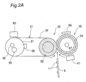
- Fig. 2A shows a pressure contact state at the time of rotation
- Fig. 2B shows a light pressure contact state at the time of stop.
- the light pressure contact state at the time of stop aims at preventing creep deformation of a fixing roller 52 which has a sponge layer.
- the light pressure contact state is also used as an envelope paper feed mode for a thick sheet of paper. The thick sheet of paper suffers paper-wrinkling if it is fed in the pressure contact state.
- the fixing-side rotation unit 31 has a heating roller 51, a fixing roller 52 and a fixing belt 53.
- the heating roller 51 is 30mm in outer diameter and 330mm in axial length, for example.
- the heating roller 51 has an aluminum hollow cored bar (0.6mm in thickness) and a PTFE (Polytetrafluoroethylene) coating (15 micrometers in thickness), for example.
- the fixing roller 52 is 30mm in outer diameter and has an iron solid core bar (22mm in diameter), a rubber (4mm in thickness), and a sponge (2mm in thickness), for example.
- the fixing belt 53 is 60mm in outer diameter and has a nickel base material (35 micrometers in thickness), a rubber (200 micrometers in thickness), and a PFA (30 micrometers in thickness), for example.
- the pressure-side rotation unit 32 has a pressure roller 54.
- the pressure roller 54 is 35mm in outer diameter and has an iron hollow cored bar (2.5mm in thickness), a rubber (2.5mm in thickness), and a PFA (Perfluoroalkoxy, 30 micrometers in thickness), for example.
- a fixing-side heating section is provided to heat the fixing-side rotation unit 31.
- the fixing-side heating section is composed of a heating-side long heater 55 and a heating-side short heater 56, which are incorporated in the heating roller 51.
- the heating-side long heater 55 is exemplified by a halogen lamp heater (1150W, emission length of 290mm), and the heating-side short heater 56 is exemplified by a halogen lamp heater (790W, emission length of 180mm).
- a pressure-side heating section is provided to heat the pressure-side rotation unit 32.
- the pressure-side heating section is constituted of a pressure-side heater 57, which is incorporated in the pressure roller 54.
- the pressure-side heater 57 is exemplified by a halogen lamp heater (230W, emission length of 290mm).
- the fixing-side heating section and the pressure-side heating section are not turned on at the same time. Specifically, they are so structured that ON/OFF control of the pressure-side heating section is operated only when the fixing-side heating section is turned off in the state where the fixing-side heating section is subjected to ON/OFF control. This means that current is preferentially passed to the fixing-side heating section, and therefore the pressure-side heating section is not turned on when the fixing-side heating section is in the ON state.
- a first temperature sensor is provided to detect the temperature of the fixing-side rotation unit 31.
- the first temperature sensor is constituted of a heating-side thermistor 58, which is placed in contact with the heating roller 51.
- a second temperature sensor is provided to detect the temperature of the pressure-side rotation unit 32.
- the second temperature sensor is constituted of a pressure-side thermistor 59, which is placed in non-contact with the pressure roller 54.
- a heating-side thermostat 60 is provided to control the temperature of the fixing-side rotation unit 31.
- the heating-side thermostat 60 is placed 1mm away from the fixing belt 53 near the center of the axial-direction of the fixing belt 53.
- a pressure-side thermostat 61 is provided to control the temperature of the pressure-side rotation unit 32.
- the pressure-side thermostat 61 is placed 1mm away from the pressure roller 54 near the center of the axial-direction of the pressure roller 54.
- a warm-up operation An operation for heating the surface of the fixing belt 53 and the pressure roller 54 up to a printable temperature after power-on of the apparatus is referred to as a warm-up operation.
- a time taken for this operation is referred to as a warm-up time.
- the warm-up operation is performed at the time of the power source being turned on again after being turned off, and at the time of return from unjamming operation, cover closing, return from a sleep mode or the like.
- the heating-side long heater 55 is turned on to raise the temperature to the printable temperature.
- the heating-side long heater 55 is maintained in the ON state, and therefore the pressure-side heater 57 is put in the OFF state, as stated above.
- the pressure roller 54 and the fixing roller 52 are in a light pressure contact state so as to prevent any creep deformation of the fixing roller 52.
- the pressure roller 54 and the fixing roller 52 are put in full pressure-contact state.
- driving force is transmitted to an unshown drive gear in order to rotate the pressure roller 54, so that the fixing belt 53, the fixing roller 52 and the heating roller 51 are rotated by following the rotation of the pressure roller 54.
- heat from insides of the heating roller 51 and the pressure roller 54 is transferred to the fixing belt 53 and the surface of the pressure roller 54.
- the heater Upon power-on of the apparatus, the heater is turned on and the roller starts to rotate. Turning-on of the heater and rotation of the roller allow the fixing belt 53 and the surface of the pressure roller 54 to be heated up to the printable temperature.
- a "ready" flag indicating permission of printing is set when not only temperature detected by the heating-side thermistor 58 reaches a predetermined printable temperature, but also corrected temperature, which is obtained by adding a non-contact segment to temperature detected by the pressure-side thermistor 59, reaches a predetermined printable temperature.
- the ready flag is set when the temperature detected by the heating-side thermistor 58 reaches 190 °C and the temperature corrected by adding the above-stated correction to the temperature detected by the pressure-side thermistor 59 reaches 150 °C.
- the fixing roller 52 and the pressure roller 54 are put in a light pressure contact state, and the apparatus is in a printing standby state. If the print signal is given, the fixing roller 52 and the pressure roller 54 are put in a full pressure contact state, and printing operation is started.
- the heaters 55, 56, 57 are controlled to keep certain preset temperatures.
- the preset temperature on the heating side is 190 °C, for example.
- the heating-side long heater 55 is on/off-controlled by using the detected temperature of the heating-side thermistor 58 as an input of the heater 55.
- the preset temperature on the pressure side is 150 °C, for example.
- the pressure-side heater 57 is on/off-controlled by using the corrected temperature as an input of the heater 57, wherein the corrected temperature is obtained by adding the correction to the temperature detected by the pressure-side thermistor 59. In this case, as mentioned above, the pressure-side heater 57 is not turned on as long as the heating-side long heater 55 is in the ON state.
- the fixing roller 52 and the pressure roller 54 rotate in a full pressure contact state. Thereby, the heat of the heating roller 51 and the pressure roller 54 is transferred to the surfaces of the fixing belt 53 and pressure roller 54, resulting in temperature increase.
- the preset temperature on the heating side is 190 °C for example
- the heating-side long heater 55 or the heating-side short heater 56 is on/off-controlled by using the temperature detected by the heating-side thermistor 58 as an input. Selection in the heating section to is determined by an unshown heating section selection control section.
- the heating section selection control section selects the heating-side short heater 56 in the case where images are printed on recording sheets having width of less than 216mm, while it selects the heating long heater 57 in the case where images are printed on recording sheets having width of 216mm or more.
- the pressure-side heater 57 is on/off-controlled by using the corrected temperature as an input of the pressure-side heater 57, wherein the corrected temperature is obtained by correcting the temperature detected by the pressure-side thermistor 59.
- the heating-side thermistor 58 detect no correct temperature due to some failure, current may be continuously passed to the heating-side long heater 55. As the result, the heating roller 51 may be heated above the preset temperature. This may lead to smoke generation or ignition.
- the heating-side thermostat 60 is placed as a protection section against such an overdrive.
- the heating-side thermostat 60 is electrically connected to the heating-side long heater 55 and the heating-side short heater 56 in series, respectively. Therefore, when the heating-side thermostat 60 operates to turn off, electric power supply to the long heater 55 and the short heater 56 is blocked. Heat is transmitted from the heating roller 51 to the fixing belt 53, and then from the fixing belt 53 to the heating-side thermostat 60.
- the preset temperature of the heating-side thermostat 60 is 210 °C for example, the thermostat 60 operates to turn off at the time of reaching the temperature of 210 °C. Thereby, electric power supply to the long heater 55 and the short heater 56 is blocked to prevent further increase in temperature.
- the long heater 55 is selectively turned on.
- the short heater 56 is selectively turned on, so as to prevent temperature rise at the axial end sections of the heating roller 51. If the end sections of the heating roller 51 are kept at a high temperature, the lifetime of the fixing device is shortened. Also, uneven distribution in the axial temperature of the heating roller 51 may cause uneven distribution in quality of axial fixed image, paper wrinkling or other problems. Thus, there are preferably provided a plurality of the heating sections having different heating regions.
- a noncontact-type temperature sensing device For measuring a temperature on the surface of the fixing belt 53, a noncontact-type temperature sensing device is sometimes employed because a contact-type temperature sensing device easily gives damage to the fixing belt 53 by direct contact with the surface of the fixing belt 53 to result in an image noise.
- the noncontact-type temperature sensing device is less preferable since it provides a temperature gap larger than that in the contact-type device. Therefore, it is preferable to employ a contact-type temperature sensing device, and particularly, to place a contact-type thermistor 58 on the heating roller 51. Detection of the surface temperature of the heating roller 51 makes it possible to more stabilize the temperature of the fixing belt 53 in front of the nip section than detection of the surface temperature of the fixing belt 53.
- the control device 18 in the image forming apparatus has a warm-up operation control section 21.
- the warm-up operation control section 21 performs warm-up operation of the fixing-side rotation unit 31 and the pressure-side rotation unit 32 from start-up until the temperature of the fixing-side rotation unit 31 exceeds a specified value, based on an output of the heating-side thermistor 58
- the warm-up operation control section 21 performs warm-up operation of the fixing-side rotation unit 31 and the pressure-side rotation unit 32 from start-up until the temperature of the pressure-side rotation unit 32 exceeds an other specified value, based on an output of the pressure-side thermistor 59.
- the monochrome image herein refers to an image in which one layer of toner t in one color is formed on a recording material S.
- the color image refers to an image in which a plurality of layers (e.g., 2 to 3 layers) of toner t in different colors is formed on a recording material S.
- the required fixing quality for the monochrome image is that a surface image made of single-layered toner t should not be removed even by friction between paper sheets or the like.
- the warm-up conditions for fixing the monochrome image are determined based on the temperature of the heating roller 51 (fixing belt 53) located on the image surface side.
- the required fixing quality for the color image is that the lower side of the multi-layered toner t should be melted to be adhered onto a paper sheet.
- the warm-up conditions for fixing the color image are determined based on the temperature of the pressure roller 54 located on the non-image surface side.
- the warm-up operation control section 21 may perform warm-up operation of the fixing-side rotation unit 31 and the pressure-side rotation unit 32 from start-up till it is determined that the temperature of the fixing-side rotation unit 31 exceeds the specified value based on an output of the heating-side thermistor 58 and that the temperature of the pressure-side rotation unit 32 exceeds the other specified value based on an output of the pressure-side thermistor 59.
- the specified value of the fixing-side rotation unit 31 is higher than the other specified value of the pressure-side rotation unit 32.
- a time taken from start-up until the temperature of the fixing-side rotation unit 31 exceeds the specified value is shorter than a time taken from start-up until the temperature of the pressure-side rotation unit 32 exceeds the other specified value.
- Fig. 4 shows the relation between temperature of the heating roller and temperature of the pressure roller, and shows completion conditions of the warm-up for fixing operation in monochrome and color modes.
- the temperature rising rate of the fixing belt 53 located on the image surface side is very high. Therefore, the heating roller 51 first reaches a monochrome image fixable temperature ("READY TEMPERATURE OF HEATING ROLLER” in Fig. 4 ), so that a monochrome print permission (“MONOCHROME READY” in Fig. 4 ) is issued.
- a monochrome print permission (“MONOCHROME READY” in Fig. 4 ) is issued.
- the heating roller 51 is continuously rotated at the temperature higher than the monochrome image fixable temperature in order to raise the temperature of the pressure roller 54 as quickly as possible. Thereafter, the temperature of the pressure roller 54 reaches a prescribed temperature ("READY TEMPERATURE OF PRESSURE ROLLER” in Fig. 4 ), and then a color print permission ("COLOR READY" in Fig. 4 ) is issued.
- the paper sheet surface is required to have a sufficiently high temperature. Therefore, a condition setting thereof is conducted by setting a temperature of the heating roller to the ready temperature of heating roller. In the case of the color image, the paper sheet back surface is required to have a sufficiently high temperature. Therefore, a condition setting thereof is conducted by setting a temperature of the pressure roller to the ready temperature of the pressure roller.
- Step S1 a power supply is turned on (Step S1). Then, the pressure roller contacts the fixing roller at full pressure (Step S2). The pressure roller is rotated to rotate the fixing belt together (Step S3).
- the heating roller is heated till temperature of the heating roller Th exceeds a specified value Th1 (Step S4). Then, a monochrome print permission is issued (Step S5).
- the pressure roller is heated till temperature of pressure roller Tp exceeds an other specified value Tp1 (Step S6). Then, a color print permission is issued (Step S7).
- Step S8 the temperature of the heating roller is adjusted to be a prescribed temperature Th2 (Th2>Th1) (Step S8).
- the pressure roller is heated till temperature of pressure roller Tp exceeds a prescribed value Tp2 (Tp2>Tp1) (Step S9), before the pressure roller is stopped (Step S10).
- the pressure roller contacts the fixing roller at light pressure (Step S11), and then, the apparatus is put in a standby state (Step S12).
- the warm-up operation control section 21 performs warm-up operation of the fixing-side rotation unit 31 and the pressure-side rotation from start-up unit 32 until the temperature of the fixing-side rotation unit 31 exceeds a specified value, based on an output of the heating-side thermistor 58.
- the warm-up operation control section 21 performs warm-up operation of the fixing-side rotation unit 31 and the pressure-side rotation unit 32 from start-up until the temperature of the pressure-side rotation unit 32 exceeds an other specified value, based on an output of the pressure-side thermistor 59.
- Time required for the temperature of the fixing-side rotation unit to exceed the specified value is shorter than time required for temperature of the pressure-side rotation unit to exceed the other specified value. Therefore, in the case of forming the monochrome image, it is not necessary to put the apparatus in a standby state until the temperature of the pressure-side rotation unit 32 exceeds the other specified value.
- the warm-up time in using the monochrome mode can be reduced, and thereby the waiting time of the users using the monochrome mode can be reduced.
- the warm-up operation control section 21 performs warm-up operation of the fixing-side rotation unit 31 and the pressure-side rotation unit 32 from start-up not only until it is determined that the temperature of the fixing-side rotation unit 31 exceeds the specified value, based on an output of the heating-side thermistor 58, but also until it is determined that the temperature of the pressure-side rotation unit 32 exceeds the other specified value from start-up till, based on an output of the pressure-side thermistor 59.
- the specified value of the fixing-side rotation unit 31 is higher than the other specified value of the pressure-side rotation unit 32, so that good formation of the color image is ensured.
- the pressure-side rotation unit 32 may be heated via the fixing-side rotation unit 31 by the fixing-side heating section (heating-side heaters 55, 56) without the pressure-side heating section (the pressure-side heater 57).
- the fixing-side rotation unit 31 may be formed into a single roller.
- the pressure-side rotation unit 32 may be formed into a pair of rollers with a belt.
- the fixing-side heating section and the pressure-side heating section may have an electromagnetic induction heating structure instead of the commonly-used heater.
- the first temperature sensor and the second temperature sensor may be constituted by thermocouples instead of thermistors.
- the image forming apparatus may be any apparatus including monochrome/collar copying machines, printers, facsimiles, and multifunctional machines having these functions.
Landscapes
- Physics & Mathematics (AREA)
- General Physics & Mathematics (AREA)
- Fixing For Electrophotography (AREA)
Abstract
A warm-up operation control section performs warm-up operation of a fixing-side rotation unit and a pressure-side rotation unit from start-up until the temperature of the fixing-side rotation unit exceeds a fist specified value based on an output of a heating-side thermistor in forming a monochrome image. In forming a color image, the warm-up operation control section performs warm-up operation of the fixing-side rotation unit and the pressure-side rotation unit from start-up until the temperature of the pressure-side rotation unit exceeds a second specified value based on an output of a pressure-side thermistor. Time required for the temperature of the fixing-side rotation unit to exceed the first specified value is set shorter than time required for temperature of the pressure-side rotation unit to exceed the second specified value.
Description
- The present invention relates to an image forming apparatus such as an electrophotographic copying machine or printer.
- Conventionally, there has been an image forming apparatus wherein it is not until temperatures of both a heating roller and a pressure roller reach predetermined ones that monochrome or color printing is permitted, at the time of the warm-up operation after turn-on of power supply (see
JP 2005-189773A - The conventional image forming apparatus has both a monochrome mode and a color mode, in general. However, in most cases, the monochrome mode is used by users.
- Conventionally, completion of the warm-up operation is determined on the basis of the color-mode which requires more severe conditions in fixability than monochrome-mode. This forces the users using the apparatus in monochrome mode to wait for a longer time than necessary.
- An object of the present invention is to provide an image forming apparatus which can reduce the warm-up time and can thereby reduce waiting time of users using in the monochrome mode.
- In order to achieve the above-mentioned object, a one aspect of the present invention provides an image forming apparatus having a fixing-side rotation unit, a fixing-side heating section which heats the fixing-side rotation unit, a pressure-side rotation unit which contacts the fixing-side rotation unit to form a nip section, a first temperature sensor which detects temperature of the fixing-side rotation unit, a second temperature sensor which detects temperature of the pressure-side rotation unit, and a warm-up operation control section which performs warm-up operation of the fixing-side rotation unit and the pressure-side rotation unit from start-up until temperature of the fixing-side rotation unit exceeds a first specified value based on an output of the first temperature sensor in a case of forming a monochrome image, and which performs warm-up operation of the fixing-side rotation unit and the pressure-side rotation unit from start-up until temperature of the pressure-side rotation unit exceeds a second specified value based on an output of the second temperature sensor in a case of forming a color image, wherein time required for the temperature of the fixing-side rotation unit to exceed the first specified value is set shorter than time required for temperature of the pressure-side rotation unit to exceed the second specified value.
- Herein, the monochrome image refers to an image in which one layer of toner is formed on a recording material. The color image refers to an image in which a plurality of layers (e.g., 2 to 3 layers) of toner is formed on a recording material.
- According to the one aspect of the present invention, the image forming apparatus has the warm-up operation control section wherein time required for the temperature of the fixing-side rotation unit to exceed the first specified value is set shorter than time required for temperature of the pressure-side rotation unit to exceed the second specified value. Thus, in the case of forming a monochrome image, it is not necessary to put the image forming apparatus in a standby state until the temperature of the pressure-side rotation unit exceeds the second specified value.
- Therefore, the warm-up time in the monochrome mode can be reduced, and thereby the waiting time of the users using the monochrome mode can be reduced.
- The present invention will become more fully understood from the detailed description given hereinbelow and the accompanying drawings which are given by way of illustration only, and thus are not limitative of the present invention, and wherein:
-
Fig. 1 shows a schematic view of an image forming apparatus in one embodiment of the present invention; -
Fig. 2A shows a schematic view of a fixing device in a state of pressure contact; -
Fig. 2B shows a schematic view of the fixing device in a state of light pressure contact; -
Fig. 3 shows a block diagram of a control device; -
Fig. 4 shows a graph indicating warm-up completion conditions for fixing operation in monochrome mode and color mode in the image forming apparatus of the present invention; and -
Fig. 5 is a control flow chart of the present invention. - Hereinbelow, the present invention will be described in details in conjunction with the embodiments with reference to the drawings.
- An image forming apparatus in one embodiment of the present invention is a color printer having
image forming units 1, as shown inFig. 1 . Theimage forming units 1 respectively form color toner images of black (BK), yellow (Y), magenta (M) and cyan (C). Theimage forming units 1 for BK, Y, M, and C are respectively placed in this order from an upper stream side of anintermediate transfer belt 11 along thisbelt 11 which rotates in the direction of an arrow "A". - The
image forming unit 1 has aphotoconductor drum 2, a charging section 3 for uniformly charging thephotoconductor drum 2, anexposure section 9 for performing image exposure of thecharged photoconductor drum 2, and a developingsection 4 for developing an electrostatic latent image formed by the exposure with use of the toner of each color. The developed toner image is primarily transferred to theintermediate transfer belt 11 by aprimary transfer section 12. After the primary transfer, the toner remaining on thephotoconductor drum 2 is removed by acleaning section 5 placed downstream. Then, the toner is withdrawn from the lower side of thecleaning section 5. - More specifically, in the
image forming unit 1, the toner image developed on thephotoconductor drum 2 is transferred onto theintermediate transfer belt 11 by theprimary transfer section 12 at a contact position with theintermediate transfer belt 11. Every time theintermediate transfer belt 11 passes each of theimage forming units 1, a toner image is surprinted on theintermediate transfer belt 11, resulting in that a full color toner images are formed on theintermediate transfer belt 11. - Thereafter, the full color toner images transferred onto the
intermediate transfer belt 11 are collectively transferred onto a recording material S, such as paper sheets, on the downstream side by asecondary transfer section 13. Then, the recording material S passes through afixing device 30 so as to fix the toner images on the recording material S. Finally, the recording material S is delivered onto apaper output tray 16. Thefixing device 30 has a fixing-side rotation unit 31 and a pressure-side rotation unit 32. - The recording material S is stored in a
record sheet cassette 17 which is located at the lowermost position. The recording material S is transported to thetransfer section 13 sheet by sheet. The residual toner on theintermediate transfer belt 11 after the secondary transfer is removed from the surface of theintermediate transfer belt 11 by acleaning blade 15. Then, the residual toner is transported by an unshown conveyance screw and collected in an unshown waste toner bottle. - A
control device 18 entirely controls the image forming apparatus (the color printer in this embodiment). Thecontrol device 18 sends signals corresponding to images to anexposure controller 19. Theexposure controller 19 drives each of theexposure sections 9 according to respective colors. - As shown in
Fig. 2A andFig. 2B , thefixing device 30 has a fixing-side rotation unit 31 and a pressure-side rotation unit 32. The pressure-side rotation unit 32 contacts the fixing-side rotation unit 31, and thereby a nip section is formed. Toner t is fixed onto the recording material S in the nip section. The fixing-side rotation unit 31 is placed on the side of the toner t which is to be fixed onto the recording material S. The pressure-side rotation unit 32 is placed on the opposite side to the toner t. -
Fig. 2A shows a pressure contact state at the time of rotation, whileFig. 2B shows a light pressure contact state at the time of stop. The light pressure contact state at the time of stop aims at preventing creep deformation of afixing roller 52 which has a sponge layer. The light pressure contact state is also used as an envelope paper feed mode for a thick sheet of paper. The thick sheet of paper suffers paper-wrinkling if it is fed in the pressure contact state. - The fixing-
side rotation unit 31 has aheating roller 51, afixing roller 52 and afixing belt 53. Theheating roller 51 is 30mm in outer diameter and 330mm in axial length, for example. Theheating roller 51 has an aluminum hollow cored bar (0.6mm in thickness) and a PTFE (Polytetrafluoroethylene) coating (15 micrometers in thickness), for example. Thefixing roller 52 is 30mm in outer diameter and has an iron solid core bar (22mm in diameter), a rubber (4mm in thickness), and a sponge (2mm in thickness), for example. Thefixing belt 53 is 60mm in outer diameter and has a nickel base material (35 micrometers in thickness), a rubber (200 micrometers in thickness), and a PFA (30 micrometers in thickness), for example. - The pressure-
side rotation unit 32 has apressure roller 54. Thepressure roller 54 is 35mm in outer diameter and has an iron hollow cored bar (2.5mm in thickness), a rubber (2.5mm in thickness), and a PFA (Perfluoroalkoxy, 30 micrometers in thickness), for example. - A fixing-side heating section is provided to heat the fixing-
side rotation unit 31. The fixing-side heating section is composed of a heating-sidelong heater 55 and a heating-sideshort heater 56, which are incorporated in theheating roller 51. The heating-sidelong heater 55 is exemplified by a halogen lamp heater (1150W, emission length of 290mm), and the heating-sideshort heater 56 is exemplified by a halogen lamp heater (790W, emission length of 180mm). - A pressure-side heating section is provided to heat the pressure-
side rotation unit 32. The pressure-side heating section is constituted of a pressure-side heater 57, which is incorporated in thepressure roller 54. The pressure-side heater 57 is exemplified by a halogen lamp heater (230W, emission length of 290mm). The fixing-side heating section and the pressure-side heating section are not turned on at the same time. Specifically, they are so structured that ON/OFF control of the pressure-side heating section is operated only when the fixing-side heating section is turned off in the state where the fixing-side heating section is subjected to ON/OFF control. This means that current is preferentially passed to the fixing-side heating section, and therefore the pressure-side heating section is not turned on when the fixing-side heating section is in the ON state. - A first temperature sensor is provided to detect the temperature of the fixing-
side rotation unit 31. The first temperature sensor is constituted of a heating-side thermistor 58, which is placed in contact with theheating roller 51. - A second temperature sensor is provided to detect the temperature of the pressure-
side rotation unit 32. The second temperature sensor is constituted of a pressure-side thermistor 59, which is placed in non-contact with thepressure roller 54. - A heating-
side thermostat 60 is provided to control the temperature of the fixing-side rotation unit 31. The heating-side thermostat 60 is placed 1mm away from the fixingbelt 53 near the center of the axial-direction of the fixingbelt 53. - A pressure-
side thermostat 61 is provided to control the temperature of the pressure-side rotation unit 32. The pressure-side thermostat 61 is placed 1mm away from thepressure roller 54 near the center of the axial-direction of thepressure roller 54. - Description is now given on operation of the fixing
device 30. An operation for heating the surface of the fixingbelt 53 and thepressure roller 54 up to a printable temperature after power-on of the apparatus is referred to as a warm-up operation. A time taken for this operation is referred to as a warm-up time. The warm-up operation is performed at the time of the power source being turned on again after being turned off, and at the time of return from unjamming operation, cover closing, return from a sleep mode or the like. - In the warm-up operation, the heating-side
long heater 55 is turned on to raise the temperature to the printable temperature. In this case, the heating-sidelong heater 55 is maintained in the ON state, and therefore the pressure-side heater 57 is put in the OFF state, as stated above. - At the time of stop, the
pressure roller 54 and the fixingroller 52 are in a light pressure contact state so as to prevent any creep deformation of the fixingroller 52. During rotation, thepressure roller 54 and the fixingroller 52 are put in full pressure-contact state. In the full pressure-contact state, driving force is transmitted to an unshown drive gear in order to rotate thepressure roller 54, so that the fixingbelt 53, the fixingroller 52 and theheating roller 51 are rotated by following the rotation of thepressure roller 54. Thereby, heat from insides of theheating roller 51 and thepressure roller 54 is transferred to the fixingbelt 53 and the surface of thepressure roller 54. - Upon power-on of the apparatus, the heater is turned on and the roller starts to rotate. Turning-on of the heater and rotation of the roller allow the fixing
belt 53 and the surface of thepressure roller 54 to be heated up to the printable temperature. A "ready" flag indicating permission of printing is set when not only temperature detected by the heating-side thermistor 58 reaches a predetermined printable temperature, but also corrected temperature, which is obtained by adding a non-contact segment to temperature detected by the pressure-side thermistor 59, reaches a predetermined printable temperature. For example, the ready flag is set when the temperature detected by the heating-side thermistor 58 reaches 190 °C and the temperature corrected by adding the above-stated correction to the temperature detected by the pressure-side thermistor 59 reaches 150 °C. - If no print signal is given at this point, the fixing
roller 52 and thepressure roller 54 are put in a light pressure contact state, and the apparatus is in a printing standby state. If the print signal is given, the fixingroller 52 and thepressure roller 54 are put in a full pressure contact state, and printing operation is started. - In the standby state, rotation of the fixing
roller 52 and thepressure roller 54 is stopped in the light pressure contact state, and theheaters long heater 55 is on/off-controlled by using the detected temperature of the heating-side thermistor 58 as an input of theheater 55. The preset temperature on the pressure side is 150 °C, for example. The pressure-side heater 57 is on/off-controlled by using the corrected temperature as an input of theheater 57, wherein the corrected temperature is obtained by adding the correction to the temperature detected by the pressure-side thermistor 59. In this case, as mentioned above, the pressure-side heater 57 is not turned on as long as the heating-sidelong heater 55 is in the ON state. - In start-up of printing operation, before the recording material S enters into the fixing
device 30, the fixingroller 52 and thepressure roller 54 rotate in a full pressure contact state. Thereby, the heat of theheating roller 51 and thepressure roller 54 is transferred to the surfaces of the fixingbelt 53 andpressure roller 54, resulting in temperature increase. In the case where the preset temperature on the heating side is 190 °C for example, the heating-sidelong heater 55 or the heating-sideshort heater 56 is on/off-controlled by using the temperature detected by the heating-side thermistor 58 as an input. Selection in the heating section to is determined by an unshown heating section selection control section. Specifically, the heating section selection control section selects the heating-sideshort heater 56 in the case where images are printed on recording sheets having width of less than 216mm, while it selects the heatinglong heater 57 in the case where images are printed on recording sheets having width of 216mm or more. In the case of the pressure-side temperature 150 °C, the pressure-side heater 57 is on/off-controlled by using the corrected temperature as an input of the pressure-side heater 57, wherein the corrected temperature is obtained by correcting the temperature detected by the pressure-side thermistor 59. - For example, if the heating-
side thermistor 58 detect no correct temperature due to some failure, current may be continuously passed to the heating-sidelong heater 55. As the result, theheating roller 51 may be heated above the preset temperature. This may lead to smoke generation or ignition. The heating-side thermostat 60 is placed as a protection section against such an overdrive. - The heating-
side thermostat 60 is electrically connected to the heating-sidelong heater 55 and the heating-sideshort heater 56 in series, respectively. Therefore, when the heating-side thermostat 60 operates to turn off, electric power supply to thelong heater 55 and theshort heater 56 is blocked. Heat is transmitted from theheating roller 51 to the fixingbelt 53, and then from the fixingbelt 53 to the heating-side thermostat 60. When the preset temperature of the heating-side thermostat 60 is 210 °C for example, thethermostat 60 operates to turn off at the time of reaching the temperature of 210 °C. Thereby, electric power supply to thelong heater 55 and theshort heater 56 is blocked to prevent further increase in temperature. - During the warm-up operation, the standby operation and the normal-size paper feed operation, the
long heater 55 is selectively turned on. On the other hand, in the case of the small-size paper feed operation, theshort heater 56 is selectively turned on, so as to prevent temperature rise at the axial end sections of theheating roller 51. If the end sections of theheating roller 51 are kept at a high temperature, the lifetime of the fixing device is shortened. Also, uneven distribution in the axial temperature of theheating roller 51 may cause uneven distribution in quality of axial fixed image, paper wrinkling or other problems. Thus, there are preferably provided a plurality of the heating sections having different heating regions. - For measuring a temperature on the surface of the fixing
belt 53, a noncontact-type temperature sensing device is sometimes employed because a contact-type temperature sensing device easily gives damage to the fixingbelt 53 by direct contact with the surface of the fixingbelt 53 to result in an image noise. However, the noncontact-type temperature sensing device is less preferable since it provides a temperature gap larger than that in the contact-type device. Therefore, it is preferable to employ a contact-type temperature sensing device, and particularly, to place a contact-type thermistor 58 on theheating roller 51. Detection of the surface temperature of theheating roller 51 makes it possible to more stabilize the temperature of the fixingbelt 53 in front of the nip section than detection of the surface temperature of the fixingbelt 53. - As shown in
Fig. 3 , thecontrol device 18 in the image forming apparatus has a warm-upoperation control section 21. In the case of forming a monochrome image, the warm-upoperation control section 21 performs warm-up operation of the fixing-side rotation unit 31 and the pressure-side rotation unit 32 from start-up until the temperature of the fixing-side rotation unit 31 exceeds a specified value, based on an output of the heating-side thermistor 58 In the case of forming a color image, the warm-upoperation control section 21 performs warm-up operation of the fixing-side rotation unit 31 and the pressure-side rotation unit 32 from start-up until the temperature of the pressure-side rotation unit 32 exceeds an other specified value, based on an output of the pressure-side thermistor 59. - The monochrome image herein refers to an image in which one layer of toner t in one color is formed on a recording material S. The color image refers to an image in which a plurality of layers (e.g., 2 to 3 layers) of toner t in different colors is formed on a recording material S.
- The required fixing quality for the monochrome image is that a surface image made of single-layered toner t should not be removed even by friction between paper sheets or the like. Thus, the warm-up conditions for fixing the monochrome image are determined based on the temperature of the heating roller 51 (fixing belt 53) located on the image surface side. On the other hand, the required fixing quality for the color image is that the lower side of the multi-layered toner t should be melted to be adhered onto a paper sheet. Thus, the warm-up conditions for fixing the color image are determined based on the temperature of the
pressure roller 54 located on the non-image surface side. - In the case of forming the color image, the warm-up
operation control section 21 may perform warm-up operation of the fixing-side rotation unit 31 and the pressure-side rotation unit 32 from start-up till it is determined that the temperature of the fixing-side rotation unit 31 exceeds the specified value based on an output of the heating-side thermistor 58 and that the temperature of the pressure-side rotation unit 32 exceeds the other specified value based on an output of the pressure-side thermistor 59. - The specified value of the fixing-
side rotation unit 31 is higher than the other specified value of the pressure-side rotation unit 32. A time taken from start-up until the temperature of the fixing-side rotation unit 31 exceeds the specified value is shorter than a time taken from start-up until the temperature of the pressure-side rotation unit 32 exceeds the other specified value. - Description is given on the conditions for permitting fixation of an image formation layer in the present embodiment.
Fig. 4 shows the relation between temperature of the heating roller and temperature of the pressure roller, and shows completion conditions of the warm-up for fixing operation in monochrome and color modes. - The temperature rising rate of the fixing
belt 53 located on the image surface side is very high. Therefore, theheating roller 51 first reaches a monochrome image fixable temperature ("READY TEMPERATURE OF HEATING ROLLER" inFig. 4 ), so that a monochrome print permission ("MONOCHROME READY" inFig. 4 ) is issued. When there is no print command, theheating roller 51 is continuously rotated at the temperature higher than the monochrome image fixable temperature in order to raise the temperature of thepressure roller 54 as quickly as possible. Thereafter, the temperature of thepressure roller 54 reaches a prescribed temperature ("READY TEMPERATURE OF PRESSURE ROLLER" inFig. 4 ), and then a color print permission ("COLOR READY" inFig. 4 ) is issued. - In the case of a monochrome image, the paper sheet surface is required to have a sufficiently high temperature. Therefore, a condition setting thereof is conducted by setting a temperature of the heating roller to the ready temperature of heating roller. In the case of the color image, the paper sheet back surface is required to have a sufficiently high temperature. Therefore, a condition setting thereof is conducted by setting a temperature of the pressure roller to the ready temperature of the pressure roller.
- With reference to
Fig. 5 , description is now given on the control flow chart of the image forming apparatus according to the embodiment. - First, a power supply is turned on (Step S1). Then, the pressure roller contacts the fixing roller at full pressure (Step S2). The pressure roller is rotated to rotate the fixing belt together (Step S3).
- The heating roller is heated till temperature of the heating roller Th exceeds a specified value Th1 (Step S4). Then, a monochrome print permission is issued (Step S5). The pressure roller is heated till temperature of pressure roller Tp exceeds an other specified value Tp1 (Step S6). Then, a color print permission is issued (Step S7).
- Thereafter, the temperature of the heating roller is adjusted to be a prescribed temperature Th2 (Th2>Th1) (Step S8). The pressure roller is heated till temperature of pressure roller Tp exceeds a prescribed value Tp2 (Tp2>Tp1) (Step S9), before the pressure roller is stopped (Step S10). The pressure roller contacts the fixing roller at light pressure (Step S11), and then, the apparatus is put in a standby state (Step S12).
- According to the above-structured image forming apparatus, in the case of forming the monochrome image, the warm-up
operation control section 21 performs warm-up operation of the fixing-side rotation unit 31 and the pressure-side rotation from start-upunit 32 until the temperature of the fixing-side rotation unit 31 exceeds a specified value, based on an output of the heating-side thermistor 58. In the case of forming the color image, the warm-upoperation control section 21 performs warm-up operation of the fixing-side rotation unit 31 and the pressure-side rotation unit 32 from start-up until the temperature of the pressure-side rotation unit 32 exceeds an other specified value, based on an output of the pressure-side thermistor 59. Time required for the temperature of the fixing-side rotation unit to exceed the specified value is shorter than time required for temperature of the pressure-side rotation unit to exceed the other specified value. Therefore, in the case of forming the monochrome image, it is not necessary to put the apparatus in a standby state until the temperature of the pressure-side rotation unit 32 exceeds the other specified value. - Thus, the warm-up time in using the monochrome mode can be reduced, and thereby the waiting time of the users using the monochrome mode can be reduced.
- Also, according to the above-structured image forming apparatus, in the case of forming the color image, the warm-up
operation control section 21 performs warm-up operation of the fixing-side rotation unit 31 and the pressure-side rotation unit 32 from start-up not only until it is determined that the temperature of the fixing-side rotation unit 31 exceeds the specified value, based on an output of the heating-side thermistor 58, but also until it is determined that the temperature of the pressure-side rotation unit 32 exceeds the other specified value from start-up till, based on an output of the pressure-side thermistor 59. In the case of forming the color image, therefore, even if the temperature of the fixing-side rotation unit 31 does not over the specified value by the time when the temperature of the pressure-side rotation unit 32 exceeds the other specified value, the warm-up operation continues until the temperature of the fixing-side rotation unit 31 exceeds the specified value. This ensures good formation of the color image. - Moreover, according to the above-structured image forming apparatus, the specified value of the fixing-
side rotation unit 31 is higher than the other specified value of the pressure-side rotation unit 32, so that good formation of the color image is ensured. - The present invention shall not be limited to the above-disclosed embodiments. For example, the pressure-
side rotation unit 32 may be heated via the fixing-side rotation unit 31 by the fixing-side heating section (heating-side heaters 55, 56) without the pressure-side heating section (the pressure-side heater 57). The fixing-side rotation unit 31 may be formed into a single roller. The pressure-side rotation unit 32 may be formed into a pair of rollers with a belt. The fixing-side heating section and the pressure-side heating section may have an electromagnetic induction heating structure instead of the commonly-used heater. Moreover, the first temperature sensor and the second temperature sensor may be constituted by thermocouples instead of thermistors. The image forming apparatus may be any apparatus including monochrome/collar copying machines, printers, facsimiles, and multifunctional machines having these functions. - The invention being thus described, it will be obvious that the invention may be varied in many ways. Such variations are not be regarded as a departure from the spirit and scope of the invention, and all such modifications as would be obvious to one skilled in the art are intended to be included within the scope of the following claims.
Claims (5)
- An image forming apparatus, comprising:a fixing-side rotation unit;a fixing-side heating section which heats the fixing-side rotation unit;a pressure-side rotation unit which contacts the fixing-side rotation unit to form a nip section;a first temperature sensor which detects temperature of the fixing-side rotation unit;a second temperature sensor which detects temperature of the pressure-side rotation unit; anda warm-up operation control section which performs warm-up operation of the fixing-side rotation unit and the pressure-side rotation unit from start-up until temperature of the fixing-side rotation unit exceeds a first specified value based on an output of the first temperature sensor in a case of forming a monochrome image, and which performs warm-up operation of the fixing-side rotation unit and the pressure-side rotation unit from start-up until temperature of the pressure-side rotation unit exceeds a second specified value based on an output of the second temperature sensor in a case of forming a color image, whereintime required for the temperature of the fixing-side rotation unit to exceed the first specified value is set shorter than time required for temperature of the pressure-side rotation unit to exceed the second specified value.
- The image forming apparatus set forth in claim 1, wherein
the warm-up operation control section performs warm-up operation of the fixing-side rotation unit and the pressure-side rotation unit from start-up not only until it is determined that temperature of the fixing-side rotation unit exceeds the first specified value based on the output of the first temperature sensor, but also until it is determined that temperature of the pressure-side rotation unit exceeds the second specified value based on the output of the second temperature sensor, in case of forming the color image. - The image forming apparatus set forth in claim 1 or 2, wherein
the first specified value of the fixing-side rotation unit is higher than the second specified value of the pressure-side rotation unit. - The image forming apparatus set forth in any one of the preceding claims, wherein
the pressure-side rotation unit is heated by the fixing-side heating section via the fixing-side rotation unit. - The image forming apparatus set forth in any one of the preceding claims, further comprising:a pressure-side heating section which heats the pressure-side rotation unit, whereinthe fixing-side heating section and the pressure-side heating section are not turned on at the same time.
Applications Claiming Priority (1)
| Application Number | Priority Date | Filing Date | Title |
|---|---|---|---|
| JP2007226181A JP2009058774A (en) | 2007-08-31 | 2007-08-31 | Image forming apparatus |
Publications (1)
| Publication Number | Publication Date |
|---|---|
| EP2031462A2 true EP2031462A2 (en) | 2009-03-04 |
Family
ID=40181578
Family Applications (1)
| Application Number | Title | Priority Date | Filing Date |
|---|---|---|---|
| EP08015034A Withdrawn EP2031462A2 (en) | 2007-08-31 | 2008-08-26 | Image forming apparatus |
Country Status (4)
| Country | Link |
|---|---|
| US (1) | US20090060552A1 (en) |
| EP (1) | EP2031462A2 (en) |
| JP (1) | JP2009058774A (en) |
| CN (1) | CN101377644A (en) |
Families Citing this family (2)
| Publication number | Priority date | Publication date | Assignee | Title |
|---|---|---|---|---|
| JP5541206B2 (en) * | 2011-03-23 | 2014-07-09 | コニカミノルタ株式会社 | FIXING DEVICE, IMAGE FORMING DEVICE, FIXING DEVICE CONTROL METHOD, AND FIXING DEVICE CONTROL PROGRAM |
| JP6089322B2 (en) * | 2014-02-27 | 2017-03-08 | シャープ株式会社 | Image forming apparatus and method for starting the apparatus |
Citations (1)
| Publication number | Priority date | Publication date | Assignee | Title |
|---|---|---|---|---|
| JP2005189773A (en) | 2003-12-26 | 2005-07-14 | Konica Minolta Business Technologies Inc | Fixing device and image forming apparatus |
Family Cites Families (1)
| Publication number | Priority date | Publication date | Assignee | Title |
|---|---|---|---|---|
| JP3501964B2 (en) * | 1998-11-25 | 2004-03-02 | シャープ株式会社 | Image output processing device |
-
2007
- 2007-08-31 JP JP2007226181A patent/JP2009058774A/en active Pending
-
2008
- 2008-08-26 US US12/198,638 patent/US20090060552A1/en not_active Abandoned
- 2008-08-26 EP EP08015034A patent/EP2031462A2/en not_active Withdrawn
- 2008-08-29 CN CN200810135531.6A patent/CN101377644A/en active Pending
Patent Citations (1)
| Publication number | Priority date | Publication date | Assignee | Title |
|---|---|---|---|---|
| JP2005189773A (en) | 2003-12-26 | 2005-07-14 | Konica Minolta Business Technologies Inc | Fixing device and image forming apparatus |
Also Published As
| Publication number | Publication date |
|---|---|
| CN101377644A (en) | 2009-03-04 |
| JP2009058774A (en) | 2009-03-19 |
| US20090060552A1 (en) | 2009-03-05 |
Similar Documents
| Publication | Publication Date | Title |
|---|---|---|
| JP5963105B2 (en) | Fixing apparatus and image forming apparatus | |
| US20080131161A1 (en) | Fixing apparatus of image forming apparatus | |
| JP5598238B2 (en) | Image forming apparatus | |
| EP2385428A2 (en) | Fixing device capable of detecting wrap jam of recording sheet and image forming apparatus | |
| JP2013178472A (en) | Fixing device and image forming apparatus | |
| US8331820B2 (en) | Fixing device and image forming apparatus using same | |
| JP2014098744A (en) | Fixing device and image forming apparatus | |
| JP4314247B2 (en) | Image heating device | |
| JP2015025908A (en) | Image forming apparatus | |
| EP2031463A2 (en) | Image forming apparatus | |
| EP2031461B1 (en) | Image forming apparatus | |
| JP2011107447A (en) | Image forming apparatus | |
| JP5541206B2 (en) | FIXING DEVICE, IMAGE FORMING DEVICE, FIXING DEVICE CONTROL METHOD, AND FIXING DEVICE CONTROL PROGRAM | |
| JP2008257027A (en) | Fixing device and image forming apparatus | |
| JP2009265387A (en) | Fuser | |
| EP2031462A2 (en) | Image forming apparatus | |
| US20110311255A1 (en) | Image forming apparatus and image forming method | |
| JP4285520B2 (en) | Fixing apparatus, temperature control method for fixing apparatus, and image forming apparatus | |
| JP5404150B2 (en) | Image forming apparatus | |
| JP4902259B2 (en) | Image forming apparatus | |
| JP2017215542A (en) | Image forming apparatus, fuser, and temperature control method | |
| JP2011033998A (en) | Image heating device | |
| JP2009180755A (en) | Fixing device and image forming apparatus equipped therewith | |
| JP4615320B2 (en) | Image forming apparatus and control method | |
| JP6816488B2 (en) | Fixing device and image forming device |
Legal Events
| Date | Code | Title | Description |
|---|---|---|---|
| PUAI | Public reference made under article 153(3) epc to a published international application that has entered the european phase |
Free format text: ORIGINAL CODE: 0009012 |
|
| AK | Designated contracting states |
Kind code of ref document: A2 Designated state(s): AT BE BG CH CY CZ DE DK EE ES FI FR GB GR HR HU IE IS IT LI LT LU LV MC MT NL NO PL PT RO SE SI SK TR |
|
| AX | Request for extension of the european patent |
Extension state: AL BA MK RS |
|
| STAA | Information on the status of an ep patent application or granted ep patent |
Free format text: STATUS: THE APPLICATION HAS BEEN WITHDRAWN |
|
| 18W | Application withdrawn |
Effective date: 20090910 |