EP2031369A2 - Method and apparatus for detecting measurement position of resonance sensor - Google Patents
Method and apparatus for detecting measurement position of resonance sensor Download PDFInfo
- Publication number
- EP2031369A2 EP2031369A2 EP08161262A EP08161262A EP2031369A2 EP 2031369 A2 EP2031369 A2 EP 2031369A2 EP 08161262 A EP08161262 A EP 08161262A EP 08161262 A EP08161262 A EP 08161262A EP 2031369 A2 EP2031369 A2 EP 2031369A2
- Authority
- EP
- European Patent Office
- Prior art keywords
- measurement
- output signal
- measuring element
- measurement object
- characteristic curve
- Prior art date
- Legal status (The legal status is an assumption and is not a legal conclusion. Google has not performed a legal analysis and makes no representation as to the accuracy of the status listed.)
- Granted
Links
Images


Classifications
-
- G—PHYSICS
- G01—MEASURING; TESTING
- G01Q—SCANNING-PROBE TECHNIQUES OR APPARATUS; APPLICATIONS OF SCANNING-PROBE TECHNIQUES, e.g. SCANNING PROBE MICROSCOPY [SPM]
- G01Q20/00—Monitoring the movement or position of the probe
- G01Q20/04—Self-detecting probes, i.e. wherein the probe itself generates a signal representative of its position, e.g. piezoelectric gauge
-
- G—PHYSICS
- G01—MEASURING; TESTING
- G01B—MEASURING LENGTH, THICKNESS OR SIMILAR LINEAR DIMENSIONS; MEASURING ANGLES; MEASURING AREAS; MEASURING IRREGULARITIES OF SURFACES OR CONTOURS
- G01B21/00—Measuring arrangements or details thereof, where the measuring technique is not covered by the other groups of this subclass, unspecified or not relevant
- G01B21/02—Measuring arrangements or details thereof, where the measuring technique is not covered by the other groups of this subclass, unspecified or not relevant for measuring length, width, or thickness
- G01B21/04—Measuring arrangements or details thereof, where the measuring technique is not covered by the other groups of this subclass, unspecified or not relevant for measuring length, width, or thickness by measuring coordinates of points
- G01B21/045—Correction of measurements
-
- G—PHYSICS
- G01—MEASURING; TESTING
- G01Q—SCANNING-PROBE TECHNIQUES OR APPARATUS; APPLICATIONS OF SCANNING-PROBE TECHNIQUES, e.g. SCANNING PROBE MICROSCOPY [SPM]
- G01Q30/00—Auxiliary means serving to assist or improve the scanning probe techniques or apparatus, e.g. display or data processing devices
- G01Q30/04—Display or data processing devices
- G01Q30/06—Display or data processing devices for error compensation
Definitions
- the present invention relates to a method and apparatus for detecting a measurement position of a resonance sensor using the resonance characteristics. More specifically, the present invention relates to a method and apparatus for detecting a measurement position of a resonance sensor which are preferably used in a measuring apparatus to which a resonance sensor can be attached, such as a form measuring apparatus, a three-dimensional measuring apparatus, or an image measuring apparatus.
- the resonance sensor of the present invention detects a contact between the tip end of a measuring element and a measurement object by resonant-vibrating the measuring element in the longitudinal direction by vibrating means, obtaining an output signal depending on resonance of the measuring element by detecting means, and capturing a change in the output signal.
- Fig. 1 shows a technique which is conventionally employed in a surface texture measurement that uses a stylus, and that is performed at the nano-level.
- Fig. 1(A) shows an atomic force microscope (AFM) in which a probe 12 is moved on a measurement object 10, a fine change in the atomic force that is caused by asperity of the measurement object 10, and that is applied to the probe 12 is read, thereby visualizing the asperity of the measurement object 10.
- AFM atomic force microscope
- the physical quantity to be measured is varied depending on the sensing technique.
- the resonance sensor which was proposed in Patent Reference 1 by the assignee of the present application has a structure where, as shown in Fig. 2 , two piezoelectric elements 24, 26 respectively for vibration and detection are pasted to a measuring element (referred to as stylus) 22 in which a diamond tip, a ruby sphere, or the like having a diameter on the order of ⁇ m is attached to the tip end 22A.
- the vibration piezoelectric element 24 of the resonance sensor 20 is driven by a vibration circuit 28 to resonantly vibrate the stylus 22 in the longitudinal direction (the vertical direction in the figure), and then an output signal depending on the resonance of the stylus 22 is obtained from the detection piezoelectric element 26.
- a detection circuit 30 detects the change in the output signal, so that the contact between the tip end 22A of the stylus and the measurement object can be sensed.
- the amplitude, frequency, and phase of the output signal of the detection piezoelectric element 26 are changed.
- the description will be made by using the change in the amplitude of the detection signal.
- the stylus 22 is contacted with the measurement object, energy dissipation is caused by the interaction, and the amplitude of the resonance signal is reduced.
- the amplitude of the detection signal shows the characteristic curve with respect to the distance between the stylus and the measurement object in which, as exemplified in Fig.
- the signal amplitude gradually decreases in proportion to the indentation amount after the position (contact point) where the stylus 22 begins to contact the surface of the measurement object 10. Therefore, a threshold (90% in the illustrated example) is set in the signal amplitude, a trigger signal is generated at the timing when the signal amplitude crosses the threshold, and the coordinate position of the tip end 22A of the stylus at that timing is read as a measurement point, so that the system can be used as a touch-trigger sensor to measure the coordinate.
- Patent Reference 1 Japanese Patent Application Publication No. 2002-393737
- Patent Reference 2 Japanese Patent Application Publication No. Hei. 10-111143
- Patent Reference 3 Japanese Patent Application Publication No. Hei. 6-3140
- the stylus 22 has a thin plate-like shape, and the resonance sensor 20 is not a sensor which is isotropic with respect to the elastic force produced by the measurement object 10. Therefore, the characteristic curve is changed by the direction dependency. Furthermore, it is considered that, in the range where the surface of the measurement object is not damaged, the characteristic curve is based on the elastic interaction between the stylus and the surface of the measurement object. Therefore, the characteristic curve is changed also by the materials of the tip end 22A of the stylus and the resonance sensor 20, and the production lots of the piezoelectric elements 24, 26 used in the resonance sensor 20. Moreover, the characteristic curve is affected also by the environment in which the resonance sensor 20 is placed, such as the temperature and the humidity. As exemplified in Fig.
- the sensor has a problem in that, when the trigger sampling based on a threshold (80% in the illustrated example) is performed, a large measurement error is produced depending on the difference in the slope of the characteristic curve in sampling.
- Patent Reference 2 discloses a configuration where, in production of a trigger signal at a steep amplitude change point from a DC sensor signal which is obtained by detecting and extracting amplitude information from a sinusoidal output signal of a touch signal probe, and on which a low-frequency waviness component and a high-frequency noise component are superimposed, a reference signal is produced from a signal having only a low-frequency waviness component, the reference signal is compared with the DC sensor signal, and an abrupt DC level transition of the DC sensor signal is accurately sensed.
- Patent Reference 3 discloses a configuration where a measurement position is estimated from correlation with respect to a preregistered pattern. Even when these configurations are used as they are in a resonance sensor, however, a sufficient effect cannot be achieved.
- the invention has been conducted in order to solve the above-discussed conventional problem. It is an object of the invention to reduce influences which cause an error in a resonance sensor to enable an accurate measurement to be performed, thereby improving the ease of use and the reliability.
- the problem is solved by a method of detecting a measurement position of a resonance sensor which senses a contact between a tip end of a measuring element and a measurement object by resonant-vibrating the measuring element in a longitudinal direction by vibrating means, obtaining an output signal depending on resonance of the measuring element by detecting means, and capturing a change in the output signal, comprising steps of:
- data of a noncontact region which are previously obtained, and data of a contact region which are obtained in the measurement by scanning can be used.
- an apparatus for detecting a measurement position of a resonance sensor which senses a contact between a tip end of a measuring element and a measurement object by resonant-vibrating the measuring element in a longitudinal direction by vibrating means, obtaining an output signal depending on resonance of the measuring element by detecting means, and capturing a change in the output signal, the apparatus comprising:
- the burden on the measurer can be remarkably reduced, and a reliable measurement is enabled.
- the method and apparatus for detecting the measurement position of the resonance sensor according to the invention is applied a touch measurement in which a contact between the tip end of the measuring element and the measurement object is sensed.
- the conventional trigger sampling based on a threshold is not performed. Characteristic curves are observed at respective measurement points of the measurement object, and an attenuation start position of the signal amplitude corresponding to the contact start position of the tip end of a measuring element of the resonance sensor with respect to the measurement object is estimated from the obtained characteristic curves. As shown in Fig.
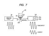
- a resonance sensor 20 of the first embodiment of the invention has a measuring element 22 with the tip end 22A, and two piezoelectric elements 24, 26 respectively for vibration and detection.
- the vibration piezoelectric element 24 of the resonance sensor 20 is driven by a vibration circuit 28, and an output signal depending on the resonance of the stylus 22 is obtained from the detection piezoelectric element 26.
- a detection circuit 130 has characteristic curve obtaining means 130a which obtains a characteristic curve showing a relationship between a distance between the measuring element and the measurement object, and a change state of the output signal, at the respective measurement points of the measurement object, and change start position estimating means 130b which estimates a change start position of the output signal corresponding to a contact start position of the tip end of the measuring element with respect to the measurement object from the characteristic curve, and detects the estimated change start position as a measurement position.
- the detection circuit 130 can estimate a regression line from each of data of the noncontact region and those of the contact region, and sets an intersection of the two obtained lines as the contact start position.
- the contact start position can be estimated and set as a measurement position.
- a control is performed so as to follow the surface of the measurement object while setting a certain point (control center point) on the slope of a characteristic curve as a center. Therefore, the output signal of a detection piezoelectric element repeats rising and falling while centered at the control center point on the characteristic curve.
- the amplitude in noncontact can be known prior to the start of the measurement by scanning. Therefore, the attenuation start position of the signal amplitude can be estimated from the obtained slope data and the amplitude in noncontact.
- the characteristic curve with respect to the amplitude of the output signal is used.
- the kind of the characteristic curve is not restricted to this, and the frequency or phase of the output signal may be used.
- the vibrating means and the detecting means are not restricted to piezoelectric elements.
Landscapes
- Physics & Mathematics (AREA)
- General Physics & Mathematics (AREA)
- Health & Medical Sciences (AREA)
- General Health & Medical Sciences (AREA)
- Nuclear Medicine, Radiotherapy & Molecular Imaging (AREA)
- Radiology & Medical Imaging (AREA)
- Measurement Of Length, Angles, Or The Like Using Electric Or Magnetic Means (AREA)
- A Measuring Device Byusing Mechanical Method (AREA)
- Length Measuring Devices With Unspecified Measuring Means (AREA)
Abstract
Description
- The present invention relates to a method and apparatus for detecting a measurement position of a resonance sensor using the resonance characteristics. More specifically, the present invention relates to a method and apparatus for detecting a measurement position of a resonance sensor which are preferably used in a measuring apparatus to which a resonance sensor can be attached, such as a form measuring apparatus, a three-dimensional measuring apparatus, or an image measuring apparatus. The resonance sensor of the present invention detects a contact between the tip end of a measuring element and a measurement object by resonant-vibrating the measuring element in the longitudinal direction by vibrating means, obtaining an output signal depending on resonance of the measuring element by detecting means, and capturing a change in the output signal.
-
Fig. 1 shows a technique which is conventionally employed in a surface texture measurement that uses a stylus, and that is performed at the nano-level. -
Fig. 1(A) shows an atomic force microscope (AFM) in which aprobe 12 is moved on ameasurement object 10, a fine change in the atomic force that is caused by asperity of themeasurement object 10, and that is applied to theprobe 12 is read, thereby visualizing the asperity of themeasurement object 10. According to the AFM, asperity of the atomic level can be observed, and the object to be measured is a surface in which the atomic force is constant. - By contrast, in a classical surface texture measuring technique using, for example, a roughness meter shown in
Fig. 1(B) , a measuring force at a level of mN is applied, and hence scratches remain in the surface of themeasurement object 10. This corresponds to a measurement which is performed on a face of a constant hardness. - As described above, the physical quantity to be measured is varied depending on the sensing technique.
- In a resonance sensor (see Patent Reference 1) which is being developed, and which uses resonance characteristics, as shown in
Fig. 1(C) , interaction between themeasurement object 10 and theprobe 12 is captured as a change in resonance characteristics. In the resonance sensor, the tip end of theprobe 12 has a diameter on the order of µm, and hence the measurement is enabled without damaging the surface of themeasurement object 10. Therefore, it is considered that the measurement is performed on a local face where the elastic force is constant. - The resonance sensor which was proposed in Patent Reference 1 by the assignee of the present application has a structure where, as shown in
Fig. 2 , twopiezoelectric elements tip end 22A. The vibrationpiezoelectric element 24 of theresonance sensor 20 is driven by avibration circuit 28 to resonantly vibrate thestylus 22 in the longitudinal direction (the vertical direction in the figure), and then an output signal depending on the resonance of thestylus 22 is obtained from the detectionpiezoelectric element 26. When thetip end 22A of thestylus 22 in the resonance state is contacted with the measurement object, resonance characteristics (frequency, phase, and amplitude) are changed according to the indentation amount, and the amplitude, frequency, and phase of the output signal (also referred to as the detection signal) of the detectionpiezoelectric element 26 are changed. Adetection circuit 30 detects the change in the output signal, so that the contact between thetip end 22A of the stylus and the measurement object can be sensed. When a scale and sensor which are used for reading the coordinate position of thetip end 22A of the stylus at the timing when the contact is sensed, or a scanning mechanism for the measurement object is provided, it is possible to perform the surface texture measurement. - As described above, when the tip end of the
stylus 22 is contacted with the measurement object, the amplitude, frequency, and phase of the output signal of the detectionpiezoelectric element 26 are changed. For the sake of simplicity, hereinafter, the description will be made by using the change in the amplitude of the detection signal. At the instant when thestylus 22 is contacted with the measurement object, energy dissipation is caused by the interaction, and the amplitude of the resonance signal is reduced. When the stylus is further pushed in, the amplitude of the detection signal shows the characteristic curve with respect to the distance between the stylus and the measurement object in which, as exemplified inFig. 3 , the signal amplitude gradually decreases in proportion to the indentation amount after the position (contact point) where thestylus 22 begins to contact the surface of themeasurement object 10. Therefore, a threshold (90% in the illustrated example) is set in the signal amplitude, a trigger signal is generated at the timing when the signal amplitude crosses the threshold, and the coordinate position of thetip end 22A of the stylus at that timing is read as a measurement point, so that the system can be used as a touch-trigger sensor to measure the coordinate. - [Patent Reference 1] Japanese Patent Application Publication No.
2002-393737
[Patent Reference 2] Japanese Patent Application Publication No.Hei. 10-111143
[Patent Reference 3] Japanese Patent Application Publication No.Hei. 6-3140 - However, the
stylus 22 has a thin plate-like shape, and theresonance sensor 20 is not a sensor which is isotropic with respect to the elastic force produced by themeasurement object 10. Therefore, the characteristic curve is changed by the direction dependency. Furthermore, it is considered that, in the range where the surface of the measurement object is not damaged, the characteristic curve is based on the elastic interaction between the stylus and the surface of the measurement object. Therefore, the characteristic curve is changed also by the materials of thetip end 22A of the stylus and theresonance sensor 20, and the production lots of thepiezoelectric elements resonance sensor 20. Moreover, the characteristic curve is affected also by the environment in which theresonance sensor 20 is placed, such as the temperature and the humidity. As exemplified inFig. 4 , these influences appear as a difference in the slope of the characteristic curve. Therefore, the sensor has a problem in that, when the trigger sampling based on a threshold (80% in the illustrated example) is performed, a large measurement error is produced depending on the difference in the slope of the characteristic curve in sampling. - On the other hand, Patent Reference 2 discloses a configuration where, in production of a trigger signal at a steep amplitude change point from a DC sensor signal which is obtained by detecting and extracting amplitude information from a sinusoidal output signal of a touch signal probe, and on which a low-frequency waviness component and a high-frequency noise component are superimposed, a reference signal is produced from a signal having only a low-frequency waviness component, the reference signal is compared with the DC sensor signal, and an abrupt DC level transition of the DC sensor signal is accurately sensed. Patent Reference 3 discloses a configuration where a measurement position is estimated from correlation with respect to a preregistered pattern. Even when these configurations are used as they are in a resonance sensor, however, a sufficient effect cannot be achieved.
- The invention has been conducted in order to solve the above-discussed conventional problem. It is an object of the invention to reduce influences which cause an error in a resonance sensor to enable an accurate measurement to be performed, thereby improving the ease of use and the reliability.
- In the invention, the problem is solved by a method of detecting a measurement position of a resonance sensor which senses a contact between a tip end of a measuring element and a measurement object by resonant-vibrating the measuring element in a longitudinal direction by vibrating means, obtaining an output signal depending on resonance of the measuring element by detecting means, and capturing a change in the output signal, comprising steps of:
- obtaining a characteristic curve showing a relationship between a distance between the measuring element and the measurement object, and a change state of the output signal, at the respective measurement points of the measurement object, and
- estimating a change start position of the output signal corresponding to a contact start position of the tip end of the measuring element with respect to the measurement object from the characteristic curve, and detecting the estimated change start position as a measurement position.
- In the configuration, in a touch measurement, data extending over a noncontact region and a contact region can be obtained.
- Alternatively, in a measurement by scanning, data of a noncontact region which are previously obtained, and data of a contact region which are obtained in the measurement by scanning can be used.
- In the invention, similarly, the problem is solved by an apparatus for detecting a measurement position of a resonance sensor which senses a contact between a tip end of a measuring element and a measurement object by resonant-vibrating the measuring element in a longitudinal direction by vibrating means, obtaining an output signal depending on resonance of the measuring element by detecting means, and capturing a change in the output signal, the apparatus comprising:
- characteristic curve obtaining means for obtaining a characteristic curve showing a relationship between a distance between the measuring element and the measurement object, and a change state of the output signal, at the respective measurement points of the measurement object; and
- change start position estimating means for estimating a change start position of the output signal corresponding to a contact start position of the tip end of the measuring element with respect to the measurement object from the characteristic curve, and detecting the estimated change start position as a measurement position.
- According to the invention, when estimation of a change start position of the output signal, that is, the measurement position is performed, influences due to the material of the measurement object, the individual variability and direction dependency of the sensor, and the measurement environment are reduced, and a more accurate measurement is enabled. At the same time, a calibration measurement and correction process which are conducted for correcting the influences causing an error, and which are cumbersome are not necessary. Therefore, the burden on the measurer can be remarkably reduced, and a reliable measurement is enabled.
- Examples of methods and apparatus in accordance with the present invention will now be described with reference to the accompanying drawings, in which:
-
Fig. 1 is a view comparingly showing principles of surface measurements using a stylus. -
Fig. 2 is a view showing the measurement principle of a resonance sensor. -
Fig. 3 is a view illustrating an example of a characteristic curve showing a relationship between a distance between a stylus and a measurement object, and an output signal. -
Fig. 4 is a view showing an example of a change of the characteristic curve. -
Fig. 5 is a view showing a characteristic curve in a first embodiment of the invention. -
Fig. 6 is a view showing a characteristic curve in a second embodiment of the invention. -
Fig. 7 is a view showing an apparatus for detecting a measurement position of the resonance sensor of the invention. -
- 10 ...
- measurement object
- 20 ...
- resonance sensor
- 22 ...
- measuring element (stylus)
- 22A ...
- tip end of measuring element
- 24 ...
- vibration piezoelectric element
- 26 ...
- detection piezoelectric element
- 28 ...
- vibration circuit
- 30 ...
- detection circuit
- Hereinafter, embodiments of the invention will be described in detail with reference to the drawings. The same reference numbers are applied to the same components as the conventional device in
Fig. 2 , and its detailed explanation will be omitted. - In a first embodiment of the invention, the method and apparatus for detecting the measurement position of the resonance sensor according to the invention is applied a touch measurement in which a contact between the tip end of the measuring element and the measurement object is sensed. In the method and apparatus for detecting the measurement position of the resonance sensor according to the first embodiment of the invention, the conventional trigger sampling based on a threshold is not performed. Characteristic curves are observed at respective measurement points of the measurement object, and an attenuation start position of the signal amplitude corresponding to the contact start position of the tip end of a measuring element of the resonance sensor with respect to the measurement object is estimated from the obtained characteristic curves. As shown in
Fig. 7 , aresonance sensor 20 of the first embodiment of the invention has a measuringelement 22 with thetip end 22A, and twopiezoelectric elements vibration piezoelectric element 24 of theresonance sensor 20 is driven by avibration circuit 28, and an output signal depending on the resonance of thestylus 22 is obtained from thedetection piezoelectric element 26. Adetection circuit 130 has characteristiccurve obtaining means 130a which obtains a characteristic curve showing a relationship between a distance between the measuring element and the measurement object, and a change state of the output signal, at the respective measurement points of the measurement object, and change start position estimating means 130b which estimates a change start position of the output signal corresponding to a contact start position of the tip end of the measuring element with respect to the measurement object from the characteristic curve, and detects the estimated change start position as a measurement position. As shown inFig. 5 , for example, thedetection circuit 130 can estimate a regression line from each of data of the noncontact region and those of the contact region, and sets an intersection of the two obtained lines as the contact start position. - According to the technique, independent from the difference of the slopes of the characteristic curves, the contact start position can be estimated and set as a measurement position.
- Next, a second embodiment of the invention in which the invention is applied to a measurement by scanning will be described in detail.
- In the measurement by scanning, as shown in
Fig. 6 , a control is performed so as to follow the surface of the measurement object while setting a certain point (control center point) on the slope of a characteristic curve as a center. Therefore, the output signal of a detection piezoelectric element repeats rising and falling while centered at the control center point on the characteristic curve. When the amplitude of the rising and falling movements is observed, therefore, it is possible to know the slope of the characteristic curve. On the other hand, the amplitude in noncontact can be known prior to the start of the measurement by scanning. Therefore, the attenuation start position of the signal amplitude can be estimated from the obtained slope data and the amplitude in noncontact. - In the embodiments described above, the characteristic curve with respect to the amplitude of the output signal is used. The kind of the characteristic curve is not restricted to this, and the frequency or phase of the output signal may be used. The vibrating means and the detecting means are not restricted to piezoelectric elements.
Claims (5)
- A method of detecting a measurement position of a resonance sensor which senses a contact between a tip end of a measuring element and a measurement object by resonant-vibrating the measuring element in a longitudinal direction by vibrating means, obtaining an output signal depending on resonance of the measuring element by detecting means, and capturing a change in the output signal, comprising steps of:obtaining a characteristic curve showing a relationship between a distance between the measuring element and the measurement object, and a change state of the output signal, at the respective measurement points of the measurement object, andestimating a change start position of the output signal corresponding to a contact start position of the tip end of the measuring element with respect to the measurement object from the characteristic curve, and detecting the estimated change start position as a measurement position.
- A method of detecting a measurement position of a resonance sensor according to claim 1, wherein, in a touch measurement, data extending over a noncontact region and a contact region are obtained.
- A method of detecting a measurement position of a resonance sensor according to claim 1, wherein, in a measurement by scanning, data of a noncontact region which are previously obtained, and data of a contact region which are obtained in the measurement by scanning are used.
- A method of detecting a measurement position of a resonance sensor according to claim 2, wherein, a regression line is estimated from each of data of the noncontact region and data of the contact region in the characteristic curve, and an intersection of the two obtained lines is estimated as the contact start position of the output signal.
- An apparatus for detecting a measurement position of a resonance sensor which senses a contact between a tip end of a measuring element and a measurement object by resonant-vibrating the measuring element in a longitudinal direction by vibrating means, obtaining an output signal depending on resonance of the measuring element by detecting means, and capturing a change in the output signal, the apparatus comprising:characteristic curve obtaining means for obtaining a characteristic curve showing a relationship between a distance between the measuring element and the measurement object, and a change state of the output signal, at the respective measurement points of the measurement object; andchange start position estimating means for estimating a change start position of the output signal corresponding to a contact start position of the tip end of the measuring element with respect to the measurement object from the characteristic curve, and detecting the estimated change start position as a measurement position.
Applications Claiming Priority (1)
| Application Number | Priority Date | Filing Date | Title |
|---|---|---|---|
| JP2007201162A JP4918427B2 (en) | 2007-08-01 | 2007-08-01 | Method and apparatus for detecting measurement position of resonance sensor |
Publications (3)
| Publication Number | Publication Date |
|---|---|
| EP2031369A2 true EP2031369A2 (en) | 2009-03-04 |
| EP2031369A3 EP2031369A3 (en) | 2010-02-24 |
| EP2031369B1 EP2031369B1 (en) | 2018-08-29 |
Family
ID=40158217
Family Applications (1)
| Application Number | Title | Priority Date | Filing Date |
|---|---|---|---|
| EP08161262.4A Ceased EP2031369B1 (en) | 2007-08-01 | 2008-07-28 | Method and apparatus for detecting measurement position of resonance sensor |
Country Status (2)
| Country | Link |
|---|---|
| EP (1) | EP2031369B1 (en) |
| JP (1) | JP4918427B2 (en) |
Cited By (1)
| Publication number | Priority date | Publication date | Assignee | Title |
|---|---|---|---|---|
| CN114440810A (en) * | 2020-11-06 | 2022-05-06 | 株式会社三丰 | Shape measuring device and abnormality detecting method |
Citations (3)
| Publication number | Priority date | Publication date | Assignee | Title |
|---|---|---|---|---|
| JPH063140A (en) | 1992-02-15 | 1994-01-11 | Carl Zeiss:Fa | Method and apparatus for measuring coordinate for machined material |
| JPH10111143A (en) | 1996-10-08 | 1998-04-28 | Mitsutoyo Corp | Detection circuit for change in dc level of sensor signal |
| JP2002039737A (en) | 2000-05-15 | 2002-02-06 | Mitsutoyo Corp | Excitation type contact detection sensor |
Family Cites Families (10)
| Publication number | Priority date | Publication date | Assignee | Title |
|---|---|---|---|---|
| JPS5819501A (en) * | 1981-07-28 | 1983-02-04 | Mitsutoyo Mfg Co Ltd | Method and device for detecting touching signal |
| JPH07167638A (en) * | 1993-12-15 | 1995-07-04 | Nikon Corp | Touch probe |
| JP3754821B2 (en) * | 1998-07-09 | 2006-03-15 | 日本電子株式会社 | Cantilever amplitude measuring method and non-contact atomic force microscope |
| US6810597B2 (en) * | 1999-04-08 | 2004-11-02 | Renishaw Plc | Use of surface measuring probes |
| JP3536013B2 (en) * | 1999-07-23 | 2004-06-07 | 株式会社ミツトヨ | Surface shape measurement method |
| JP3818928B2 (en) * | 2002-02-14 | 2006-09-06 | 株式会社ミツトヨ | Surface shape measuring method and surface shape measuring apparatus |
| JP4009152B2 (en) * | 2002-07-09 | 2007-11-14 | 株式会社ミツトヨ | Surface shape measuring apparatus and surface shape measuring method |
| EP1845361A4 (en) * | 2005-01-06 | 2011-11-30 | Univ Hokkaido Nat Univ Corp | SURFACE POSITION MEASURING METHOD AND SURFACE POSITION MEASURING DEVICE |
| JP4909548B2 (en) * | 2005-09-01 | 2012-04-04 | 株式会社ミツトヨ | Surface shape measuring device |
| JP4909562B2 (en) * | 2005-10-21 | 2012-04-04 | 株式会社ミツトヨ | Surface texture measuring device |
-
2007
- 2007-08-01 JP JP2007201162A patent/JP4918427B2/en not_active Expired - Fee Related
-
2008
- 2008-07-28 EP EP08161262.4A patent/EP2031369B1/en not_active Ceased
Patent Citations (3)
| Publication number | Priority date | Publication date | Assignee | Title |
|---|---|---|---|---|
| JPH063140A (en) | 1992-02-15 | 1994-01-11 | Carl Zeiss:Fa | Method and apparatus for measuring coordinate for machined material |
| JPH10111143A (en) | 1996-10-08 | 1998-04-28 | Mitsutoyo Corp | Detection circuit for change in dc level of sensor signal |
| JP2002039737A (en) | 2000-05-15 | 2002-02-06 | Mitsutoyo Corp | Excitation type contact detection sensor |
Cited By (1)
| Publication number | Priority date | Publication date | Assignee | Title |
|---|---|---|---|---|
| CN114440810A (en) * | 2020-11-06 | 2022-05-06 | 株式会社三丰 | Shape measuring device and abnormality detecting method |
Also Published As
| Publication number | Publication date |
|---|---|
| EP2031369B1 (en) | 2018-08-29 |
| JP4918427B2 (en) | 2012-04-18 |
| JP2009036632A (en) | 2009-02-19 |
| EP2031369A3 (en) | 2010-02-24 |
Similar Documents
| Publication | Publication Date | Title |
|---|---|---|
| CN107543484B (en) | Method for operating a coordinate measuring machine | |
| US8844061B2 (en) | Scanning probe microscope | |
| EP1760422B1 (en) | Surface profile measuring instrument | |
| EP1382934A3 (en) | Surface profile measuring instrument and surface profile measuring method | |
| JP3961258B2 (en) | Touch sensor and probe for fine shape measuring device | |
| US7631548B2 (en) | Scanning probe microscope | |
| TW200415340A (en) | Method and apparatus for measuring object thickness | |
| Hidaka et al. | Study of a small-sized ultrasonic probe | |
| US9335151B2 (en) | Film measurement | |
| EP2031369B1 (en) | Method and apparatus for detecting measurement position of resonance sensor | |
| RU2442131C1 (en) | Method for measuring surface texture properties and mechanical properties of the materials | |
| KR102180526B1 (en) | Potable surface measurement device and controlling method thereof | |
| CN104950142B (en) | Method for measuring vibration characteristics of cantilever and device for measuring vibration characteristics of cantilever | |
| CN102981022B (en) | The spring constant of cantilever determines method and uses the scanning type probe microscope of the method | |
| JP3624607B2 (en) | Surface hardness measuring device | |
| JP2001264373A (en) | Apparatus and method for measuring piezoelectric constant of piezoelectric thin film | |
| JP2009139188A (en) | Ultrasonic apparatus for measuring surface roughness and method therefor | |
| US7617720B2 (en) | Surface position measuring method and surface position measuring device | |
| JP2006308312A (en) | Probe tip evaluation method for scan type probe microscope | |
| US6434845B1 (en) | Dual-axis static and dynamic force characterization device | |
| JP2003130632A (en) | Method and apparatus for detecting abnormal measurement of touch signal probe | |
| JP5032235B2 (en) | Method and apparatus for detecting measurement position of resonance sensor | |
| RU167852U1 (en) | DEVICE FOR MEASURING MECHANICAL PROPERTIES OF MATERIALS | |
| JP2001056216A (en) | Device for determining position of object on surface | |
| KR100595138B1 (en) | Operation Method of Surface Condition Sensing Device of Semiconductor Device |
Legal Events
| Date | Code | Title | Description |
|---|---|---|---|
| PUAI | Public reference made under article 153(3) epc to a published international application that has entered the european phase |
Free format text: ORIGINAL CODE: 0009012 |
|
| AK | Designated contracting states |
Kind code of ref document: A2 Designated state(s): AT BE BG CH CY CZ DE DK EE ES FI FR GB GR HR HU IE IS IT LI LT LU LV MC MT NL NO PL PT RO SE SI SK TR |
|
| AX | Request for extension of the european patent |
Extension state: AL BA MK RS |
|
| PUAL | Search report despatched |
Free format text: ORIGINAL CODE: 0009013 |
|
| AK | Designated contracting states |
Kind code of ref document: A3 Designated state(s): AT BE BG CH CY CZ DE DK EE ES FI FR GB GR HR HU IE IS IT LI LT LU LV MC MT NL NO PL PT RO SE SI SK TR |
|
| AX | Request for extension of the european patent |
Extension state: AL BA MK RS |
|
| 17P | Request for examination filed |
Effective date: 20100823 |
|
| AKX | Designation fees paid |
Designated state(s): DE FR GB |
|
| 17Q | First examination report despatched |
Effective date: 20161004 |
|
| REG | Reference to a national code |
Ref country code: DE Ref legal event code: R079 Ref document number: 602008056675 Country of ref document: DE Free format text: PREVIOUS MAIN CLASS: G01N0013100000 Ipc: G01Q0020040000 |
|
| GRAP | Despatch of communication of intention to grant a patent |
Free format text: ORIGINAL CODE: EPIDOSNIGR1 |
|
| RIC1 | Information provided on ipc code assigned before grant |
Ipc: G01Q 30/06 20100101ALI20180302BHEP Ipc: G01Q 20/04 20100101AFI20180302BHEP Ipc: G01B 21/04 20060101ALI20180302BHEP |
|
| INTG | Intention to grant announced |
Effective date: 20180326 |
|
| RAP1 | Party data changed (applicant data changed or rights of an application transferred) |
Owner name: MITUTOYO CORPORATION |
|
| RIN1 | Information on inventor provided before grant (corrected) |
Inventor name: GOTO, TOMONORI |
|
| GRAS | Grant fee paid |
Free format text: ORIGINAL CODE: EPIDOSNIGR3 |
|
| GRAA | (expected) grant |
Free format text: ORIGINAL CODE: 0009210 |
|
| AK | Designated contracting states |
Kind code of ref document: B1 Designated state(s): DE FR GB |
|
| REG | Reference to a national code |
Ref country code: GB Ref legal event code: FG4D |
|
| REG | Reference to a national code |
Ref country code: DE Ref legal event code: R096 Ref document number: 602008056675 Country of ref document: DE |
|
| REG | Reference to a national code |
Ref country code: DE Ref legal event code: R097 Ref document number: 602008056675 Country of ref document: DE |
|
| PLBE | No opposition filed within time limit |
Free format text: ORIGINAL CODE: 0009261 |
|
| STAA | Information on the status of an ep patent application or granted ep patent |
Free format text: STATUS: NO OPPOSITION FILED WITHIN TIME LIMIT |
|
| 26N | No opposition filed |
Effective date: 20190531 |
|
| PGFP | Annual fee paid to national office [announced via postgrant information from national office to epo] |
Ref country code: GB Payment date: 20230720 Year of fee payment: 16 |
|
| PGFP | Annual fee paid to national office [announced via postgrant information from national office to epo] |
Ref country code: FR Payment date: 20230725 Year of fee payment: 16 Ref country code: DE Payment date: 20230719 Year of fee payment: 16 |
|
| REG | Reference to a national code |
Ref country code: DE Ref legal event code: R119 Ref document number: 602008056675 Country of ref document: DE |
|
| GBPC | Gb: european patent ceased through non-payment of renewal fee |
Effective date: 20240728 |
|
| PG25 | Lapsed in a contracting state [announced via postgrant information from national office to epo] |
Ref country code: DE Free format text: LAPSE BECAUSE OF NON-PAYMENT OF DUE FEES Effective date: 20250201 |
|
| PG25 | Lapsed in a contracting state [announced via postgrant information from national office to epo] |
Ref country code: FR Free format text: LAPSE BECAUSE OF NON-PAYMENT OF DUE FEES Effective date: 20240731 |
|
| PG25 | Lapsed in a contracting state [announced via postgrant information from national office to epo] |
Ref country code: GB Free format text: LAPSE BECAUSE OF NON-PAYMENT OF DUE FEES Effective date: 20240728 |