EP2030886A2 - Fiber-reinforced wrapped handlebar-steered suspension fork - Google Patents
Fiber-reinforced wrapped handlebar-steered suspension fork Download PDFInfo
- Publication number
- EP2030886A2 EP2030886A2 EP20080014628 EP08014628A EP2030886A2 EP 2030886 A2 EP2030886 A2 EP 2030886A2 EP 20080014628 EP20080014628 EP 20080014628 EP 08014628 A EP08014628 A EP 08014628A EP 2030886 A2 EP2030886 A2 EP 2030886A2
- Authority
- EP
- European Patent Office
- Prior art keywords
- outer tube
- fiber
- radial load
- handlebar
- wrapped
- Prior art date
- Legal status (The legal status is an assumption and is not a legal conclusion. Google has not performed a legal analysis and makes no representation as to the accuracy of the status listed.)
- Granted
Links
Images
Classifications
-
- B—PERFORMING OPERATIONS; TRANSPORTING
- B62—LAND VEHICLES FOR TRAVELLING OTHERWISE THAN ON RAILS
- B62K—CYCLES; CYCLE FRAMES; CYCLE STEERING DEVICES; RIDER-OPERATED TERMINAL CONTROLS SPECIALLY ADAPTED FOR CYCLES; CYCLE AXLE SUSPENSIONS; CYCLE SIDECARS, FORECARS, OR THE LIKE
- B62K25/00—Axle suspensions
- B62K25/04—Axle suspensions for mounting axles resiliently on cycle frame or fork
- B62K25/06—Axle suspensions for mounting axles resiliently on cycle frame or fork with telescopic fork, e.g. including auxiliary rocking arms
- B62K25/08—Axle suspensions for mounting axles resiliently on cycle frame or fork with telescopic fork, e.g. including auxiliary rocking arms for front wheel
Definitions
- the present invention relates to handlebar-steered suspension forks, and more particularly, to a handlebar-steered suspension fork that includes a fiber-reinforced material wrapped about radial load regions of an outer tube of the fork and not wrapped about transition regions of the outer tube.
- the strength of a handlebar-steered suspension fork may be increased by selectively wrapping the fork with a fiber-reinforced material according to one embodiment of the present invention.
- the handlebar-steered suspension fork includes an outer tube and an inner tube reciprocally slidable within the outer tube.
- the outer tube includes at least one radial load region and at least one transition region.
- a fiber-reinforced material is wrapped about at least one of the outer tube radial load regions and not wrapped about at least one of the outer tube transition regions.
- the fork includes a bushing disposed between the outer and inner tubes.
- the bushing is configured to transmit radial load from the inner tube to the radial load region of the outer tube.
- each of the outer tube radial regions is wrapped with the fiber-reinforced material.
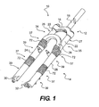
- FIG. 1 is perspective view of a suspension fork according to one embodiment of the present invention
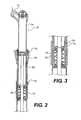
- FIG. 2 is a partial cross-sectional view of a leg of the suspension fork of the FIG. 1 ;
- FIG. 3 is an enlarged view of a portion of the leg of FIG. 2 ;
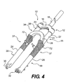
- FIG. 4 is a perspective of view of a suspension fork according to another embodiment of the present invention.
- FIGS. 1-3 illustrate a suspension fork 10 that includes fiber-reinforced material selectively wrapped about the fork 10 according to one embodiment of the present invention.
- the suspension fork 10 includes an upper housing 12 and a lower housing 14.
- the upper housing 12 includes a crown 16 connected to a steerer tube 18 and inner tubes 20, 22.
- the lower housing 14 includes outer tubes 24, 26, an arch 28 and dropouts 30, 32.
- the arch 28 connects the outer tubes 24, 26 for increased rigidity of the lower housing 14.
- the outer tubes 24, 26 and the arch 28 embody a single piece, however, the tubes 24, 26 and the arch 28 may be separate pieces fastened together.
- the dropouts 30, 32 connect the fork 10 to a wheel axle (not shown).
- the inner tubes 20, 22 are reciprocally slidable within the outer tubes 24, 26, respectively, each inner and outer tube pairing forming a leg 25, 27 of the suspension fork 10.
- the legs 25, 27 of the fork 10 may include a damping system 34 and a spring system 35.
- the outer tubes 24, 26 include radial load regions 37 and transition regions 39.
- the leg 27 includes a first bushing 68 and a second bushing 70 positioned between the inner and outer tubes 24, 26.
- the bushings 68, 70 are configured to transmit radial load from the inner tube 24 to the radial load regions 37 of the outer tube 26.
- the inner tube applies a radial or prying load to the outer tube, the outer tube resisting deflection under hoop and bending stress.
- a fiber-reinforced material 72 is selectively wrapped about the outer tube 26 at the radial load regions 37 of the outer tube 26 and not wrapped about the transition regions 39 of the outer tube 26. Further, the bushings 68, 70 inhibit wear of the inner and outer tubes 24, 26 by preventing direct contact therebetween.
- the bushings 68, 70 are typically fixed to the outer tube 26, but may alternatively be fixed to the inner tube 24.
- the fiber-reinforced material 72 may extend continuously between proximate or overlapping radial load regions 37 of the outer tube 26 (see FIG. 4 ).
- a single bushing may be used instead of paired bushings 68, 70.
- the fiber-reinforced material 72 increases the hoop strength of the outer tube 26 in these radial load regions, resulting in greater stiffness and load capacity. Further, the fiber-reinforced material 72 supports the outer tube 26 during installation and sizing of the bushings 68, 70, thereby preventing splitting of the outer tube 26 and resulting in more stable bushing performance.
- the fiber-reinforced material may include various layers of materials. The innermost layer may be an adhesive that bonds the wrap to the outer leg. The next layer may be a glass, insulative layer preventing galvanic corrosion with additional layers of unidirectional and/or weave materials for structural strength. Lastly, an outer-most layer may provide a cosmetic finished look.
- the structural layers may be carbon, glass, Kevlar or of a similar fibrous material.
Landscapes
- Engineering & Computer Science (AREA)
- Mechanical Engineering (AREA)
- Fluid-Damping Devices (AREA)
- Steering Devices For Bicycles And Motorcycles (AREA)
- Axle Suspensions And Sidecars For Cycles (AREA)
Abstract
Description
- The present invention relates to handlebar-steered suspension forks, and more particularly, to a handlebar-steered suspension fork that includes a fiber-reinforced material wrapped about radial load regions of an outer tube of the fork and not wrapped about transition regions of the outer tube.
- The strength of a handlebar-steered suspension fork may be increased by selectively wrapping the fork with a fiber-reinforced material according to one embodiment of the present invention. The handlebar-steered suspension fork includes an outer tube and an inner tube reciprocally slidable within the outer tube. The outer tube includes at least one radial load region and at least one transition region. A fiber-reinforced material is wrapped about at least one of the outer tube radial load regions and not wrapped about at least one of the outer tube transition regions.
- In one embodiment of the present invention, the fork includes a bushing disposed between the outer and inner tubes. The bushing is configured to transmit radial load from the inner tube to the radial load region of the outer tube. In another embodiment of the present invention, each of the outer tube radial regions is wrapped with the fiber-reinforced material.
- These and other features and advantages of the present invention will be more fully understood from the following description of one or more embodiments of the invention, taken together with the accompanying drawings.
- In the drawings:
-
FIG. 1 is perspective view of a suspension fork according to one embodiment of the present invention; -
FIG. 2 is a partial cross-sectional view of a leg of the suspension fork of theFIG. 1 ; -
FIG. 3 is an enlarged view of a portion of the leg ofFIG. 2 ; and -
FIG. 4 is a perspective of view of a suspension fork according to another embodiment of the present invention. -
FIGS. 1-3 illustrate asuspension fork 10 that includes fiber-reinforced material selectively wrapped about thefork 10 according to one embodiment of the present invention. Looking toFIG. 1 , thesuspension fork 10 includes anupper housing 12 and alower housing 14. Theupper housing 12 includes acrown 16 connected to asteerer tube 18 andinner tubes lower housing 14 includesouter tubes arch 28 anddropouts arch 28 connects theouter tubes lower housing 14. In this embodiment, theouter tubes arch 28 embody a single piece, however, thetubes arch 28 may be separate pieces fastened together. Thedropouts fork 10 to a wheel axle (not shown). Theinner tubes outer tubes leg suspension fork 10. Thelegs fork 10 may include adamping system 34 and aspring system 35. Theouter tubes radial load regions 37 andtransition regions 39. - Looking to
FIGS. 2 and 3 , theleg 27 includes afirst bushing 68 and asecond bushing 70 positioned between the inner andouter tubes bushings inner tube 24 to theradial load regions 37 of theouter tube 26. As the inner and outer tubes are loaded laterally with respect to the direction of suspension travel, the inner tube applies a radial or prying load to the outer tube, the outer tube resisting deflection under hoop and bending stress. To further resist the prying loads of the inner tube, without adding extraneous weight, a fiber-reinforcedmaterial 72 is selectively wrapped about theouter tube 26 at theradial load regions 37 of theouter tube 26 and not wrapped about thetransition regions 39 of theouter tube 26. Further, thebushings outer tubes bushings outer tube 26, but may alternatively be fixed to theinner tube 24. - In another embodiment of the present invention, typically in suspension forks with shorter travel, the fiber-reinforced
material 72 may extend continuously between proximate or overlappingradial load regions 37 of the outer tube 26 (seeFIG. 4 ). In similar embodiments, a single bushing may be used instead of pairedbushings - The fiber-reinforced
material 72 increases the hoop strength of theouter tube 26 in these radial load regions, resulting in greater stiffness and load capacity. Further, the fiber-reinforcedmaterial 72 supports theouter tube 26 during installation and sizing of thebushings outer tube 26 and resulting in more stable bushing performance. The fiber-reinforced material may include various layers of materials. The innermost layer may be an adhesive that bonds the wrap to the outer leg. The next layer may be a glass, insulative layer preventing galvanic corrosion with additional layers of unidirectional and/or weave materials for structural strength. Lastly, an outer-most layer may provide a cosmetic finished look. The structural layers may be carbon, glass, Kevlar or of a similar fibrous material. - While this invention has been described by reference to one or more embodiments, it should be understood that numerous changes could be made within the spirit and scope of the inventive concepts described. Accordingly, it is intended that the invention not be limited to the disclosed embodiment, but that it have the full scope permitted by the language of the following claims.
Claims (4)
- A handlebar-steered suspension fork comprising:an outer tube;an inner tube reciprocally slidable within the outer tube,the outer tube including at least one radial load region and at least one transition region; anda fiber-reinforced material wrapped about at least one of the outer tube radial load regions, the fiber-reinforced material not wrapped about at least one of the outer tube transition regions.
- The handlebar-steered suspension fork of claim 1, further comprising at least one bushing disposed between the outer and inner tubes, the bushing configured to transmit radial load from the inner tube to the radial load region of the outer tube.
- A handlebar-steered suspension fork comprising:an outer tube;an inner tube reciprocally slidable within the outer tube,the outer tube including at least one radial load region and at least one transition region; anda fiber-reinforced material wrapped about each of the outer tube radial load regions, the fiber-reinforced material not wrapped about at least one of the outer tube transition regions.
- The handlebar-steered suspension fork of claim 3, further comprising at least one bushing disposed between the outer and inner tubes, the bushing configured to transmit radial load from the inner tube to the radial load region of the outer tube.
Applications Claiming Priority (1)
| Application Number | Priority Date | Filing Date | Title |
|---|---|---|---|
| US11/847,174 US8740238B2 (en) | 2007-08-29 | 2007-08-29 | Fiber-reinforced wrapped handlebar-steered suspension fork |
Publications (4)
| Publication Number | Publication Date |
|---|---|
| EP2030886A2 true EP2030886A2 (en) | 2009-03-04 |
| EP2030886A3 EP2030886A3 (en) | 2011-07-27 |
| EP2030886B1 EP2030886B1 (en) | 2017-06-14 |
| EP2030886B8 EP2030886B8 (en) | 2017-08-23 |
Family
ID=40130829
Family Applications (1)
| Application Number | Title | Priority Date | Filing Date |
|---|---|---|---|
| EP08014628.5A Active EP2030886B8 (en) | 2007-08-29 | 2008-08-18 | Fiber-reinforced wrapped handlebar-steered suspension fork |
Country Status (4)
| Country | Link |
|---|---|
| US (1) | US8740238B2 (en) |
| EP (1) | EP2030886B8 (en) |
| CN (1) | CN101376415B (en) |
| TW (1) | TWI365830B (en) |
Families Citing this family (3)
| Publication number | Priority date | Publication date | Assignee | Title |
|---|---|---|---|---|
| CA2679522A1 (en) * | 2008-09-19 | 2010-03-19 | Vroomen/White Design Inc. | Plated bicycle fork steerer tube |
| DE102008053700A1 (en) * | 2008-10-29 | 2010-05-06 | Dt Swiss Ag | Diving tube unit for a suspension fork |
| JP2011201354A (en) * | 2010-03-24 | 2011-10-13 | Honda Motor Co Ltd | Front structure of saddle riding type vehicle |
Citations (5)
| Publication number | Priority date | Publication date | Assignee | Title |
|---|---|---|---|---|
| JPS6237138A (en) | 1985-08-12 | 1987-02-18 | Sumitomo Electric Ind Ltd | Preparation of front fork inner pipe for two wheeled vehicle |
| JPH07106712B2 (en) | 1985-12-18 | 1995-11-15 | 本田技研工業株式会社 | Inner pipe of front fork for motorcycle |
| DE29707546U1 (en) | 1997-04-28 | 1997-11-27 | Kramer, Klaus, 79294 Sölden | Telescopic suspension fork with external spring and damping element |
| JP2005180673A (en) | 2003-12-24 | 2005-07-07 | Kayaba Ind Co Ltd | Front fork |
| JP2007211790A (en) | 2006-02-07 | 2007-08-23 | Kayaba Ind Co Ltd | Front fork |
Family Cites Families (15)
| Publication number | Priority date | Publication date | Assignee | Title |
|---|---|---|---|---|
| US4971344A (en) * | 1989-01-04 | 1990-11-20 | Rockshox, Inc. | Bicycle with a front fork wheel suspension |
| US5078417A (en) * | 1989-07-19 | 1992-01-07 | Cycle Composites, Inc. | All terrain cycle fork with fiber reinforced resin blades and crown and method of making same |
| DE3938509A1 (en) * | 1989-11-20 | 1991-05-23 | Look Sa | BICYCLE FRAME |
| CA2042484C (en) * | 1991-05-13 | 1996-06-25 | Chin-San You | Ball bat |
| US6012996A (en) * | 1998-03-05 | 2000-01-11 | Shenly Won Sport Co., Ltd. | Game racket frame made of fiber reinforced plastic |
| US6036610A (en) * | 1999-03-01 | 2000-03-14 | Anderson-Bridges Interests, Inc. | Reinforced baseball bat |
| DE29907475U1 (en) * | 1999-04-27 | 1999-08-12 | Yu, Kuo-Pin, Feng Yuan, Taichung | Bicycle frame |
| US6461260B1 (en) * | 2000-05-15 | 2002-10-08 | Worth, Inc. | Composite wrap bat |
| CA2324063C (en) * | 2000-10-23 | 2005-05-10 | Remi Lussier | Hollow wooden hockey stick |
| CN2458229Y (en) | 2000-12-13 | 2001-11-07 | 台湾司普工业股份有限公司 | The front fork of the composite set wire hanger |
| US7017930B2 (en) | 2004-05-05 | 2006-03-28 | Specialized Bicycle Components, Inc. | Bicycle fork with tensioned damping member |
| TWM270111U (en) | 2004-12-31 | 2005-07-11 | Advanced Internatioanl Multite | A bicycle front handlebar stem made of composite material |
| JP4648769B2 (en) | 2005-06-16 | 2011-03-09 | 本田技研工業株式会社 | Inverted front fork |
| US7597338B2 (en) * | 2005-08-26 | 2009-10-06 | Giant Manufacturing Co., Ltd. | Bicycle frame with multiple layer tube |
| TWM312489U (en) | 2006-11-15 | 2007-05-21 | You-Liang Wu | Improved structure for shock absorber of bicycle |
-
2007
- 2007-08-29 US US11/847,174 patent/US8740238B2/en active Active
-
2008
- 2008-08-18 EP EP08014628.5A patent/EP2030886B8/en active Active
- 2008-08-19 TW TW097131540A patent/TWI365830B/en active
- 2008-08-29 CN CN2008101686709A patent/CN101376415B/en not_active Expired - Fee Related
Patent Citations (5)
| Publication number | Priority date | Publication date | Assignee | Title |
|---|---|---|---|---|
| JPS6237138A (en) | 1985-08-12 | 1987-02-18 | Sumitomo Electric Ind Ltd | Preparation of front fork inner pipe for two wheeled vehicle |
| JPH07106712B2 (en) | 1985-12-18 | 1995-11-15 | 本田技研工業株式会社 | Inner pipe of front fork for motorcycle |
| DE29707546U1 (en) | 1997-04-28 | 1997-11-27 | Kramer, Klaus, 79294 Sölden | Telescopic suspension fork with external spring and damping element |
| JP2005180673A (en) | 2003-12-24 | 2005-07-07 | Kayaba Ind Co Ltd | Front fork |
| JP2007211790A (en) | 2006-02-07 | 2007-08-23 | Kayaba Ind Co Ltd | Front fork |
Also Published As
| Publication number | Publication date |
|---|---|
| US8740238B2 (en) | 2014-06-03 |
| TWI365830B (en) | 2012-06-11 |
| TW201103808A (en) | 2011-02-01 |
| EP2030886A3 (en) | 2011-07-27 |
| CN101376415B (en) | 2013-03-13 |
| US20090058039A1 (en) | 2009-03-05 |
| EP2030886B8 (en) | 2017-08-23 |
| CN101376415A (en) | 2009-03-04 |
| EP2030886B1 (en) | 2017-06-14 |
Similar Documents
| Publication | Publication Date | Title |
|---|---|---|
| US5908200A (en) | Two wheeled vehicle fork with reinforced leg | |
| JP6186426B2 (en) | shock absorber | |
| US9027947B2 (en) | Methods and apparatus related to a unitary fork brace | |
| US20050151344A1 (en) | Living hinge member and suspension | |
| US8136758B2 (en) | Hybrid strut comprising metal and composite portions | |
| US8042766B2 (en) | Hybrid aircraft wheel comprising metal and composite portions | |
| US20120211959A1 (en) | Stabilizer for a motor vehicle | |
| US8740238B2 (en) | Fiber-reinforced wrapped handlebar-steered suspension fork | |
| US20170217502A1 (en) | Axle Support of a Motor Vehicle | |
| US9039023B2 (en) | Outer tube for front fork | |
| JPS6164581A (en) | Steering wheel made of fiber reinforced resin | |
| US8061729B2 (en) | Reinforced bicycle frame | |
| CN206860734U (en) | A kind of bushing for rear overhang rack pull bar | |
| US20130241171A1 (en) | Lower leg for a suspension fork | |
| US20040256910A1 (en) | Suspension system having a composite axle | |
| WO2015106990A1 (en) | Composite steering knuckle | |
| CN110997364A (en) | Method for manufacturing a composite torsion beam axle for vehicle rear suspension | |
| KR101673616B1 (en) | Torsion Guidance type Trailing Arm | |
| TWI667165B (en) | Split handle | |
| JPH08282570A (en) | FRP fork stem for bicycle | |
| KR101471049B1 (en) | Body frame for bikes | |
| CA2558518C (en) | Reinforced bicycle frame | |
| US20110278084A1 (en) | Front fork for a saddle-type vehicle, and vehicle incorporating same | |
| US20130161968A1 (en) | Device for transmitting a force, in particular a carrying handle | |
| CN201428767Y (en) | Built-in parallel rubber spring |
Legal Events
| Date | Code | Title | Description |
|---|---|---|---|
| PUAI | Public reference made under article 153(3) epc to a published international application that has entered the european phase |
Free format text: ORIGINAL CODE: 0009012 |
|
| AK | Designated contracting states |
Kind code of ref document: A2 Designated state(s): AT BE BG CH CY CZ DE DK EE ES FI FR GB GR HR HU IE IS IT LI LT LU LV MC MT NL NO PL PT RO SE SI SK TR |
|
| AX | Request for extension of the european patent |
Extension state: AL BA MK RS |
|
| PUAL | Search report despatched |
Free format text: ORIGINAL CODE: 0009013 |
|
| AK | Designated contracting states |
Kind code of ref document: A3 Designated state(s): AT BE BG CH CY CZ DE DK EE ES FI FR GB GR HR HU IE IS IT LI LT LU LV MC MT NL NO PL PT RO SE SI SK TR |
|
| AX | Request for extension of the european patent |
Extension state: AL BA MK RS |
|
| 17P | Request for examination filed |
Effective date: 20111125 |
|
| 17Q | First examination report despatched |
Effective date: 20120216 |
|
| AKX | Designation fees paid |
Designated state(s): DE FR NL |
|
| GRAP | Despatch of communication of intention to grant a patent |
Free format text: ORIGINAL CODE: EPIDOSNIGR1 |
|
| STAA | Information on the status of an ep patent application or granted ep patent |
Free format text: STATUS: GRANT OF PATENT IS INTENDED |
|
| INTG | Intention to grant announced |
Effective date: 20170109 |
|
| GRAS | Grant fee paid |
Free format text: ORIGINAL CODE: EPIDOSNIGR3 |
|
| GRAA | (expected) grant |
Free format text: ORIGINAL CODE: 0009210 |
|
| STAA | Information on the status of an ep patent application or granted ep patent |
Free format text: STATUS: THE PATENT HAS BEEN GRANTED |
|
| GRAT | Correction requested after decision to grant or after decision to maintain patent in amended form |
Free format text: ORIGINAL CODE: EPIDOSNCDEC |
|
| AK | Designated contracting states |
Kind code of ref document: B1 Designated state(s): DE FR NL |
|
| RAP1 | Party data changed (applicant data changed or rights of an application transferred) |
Owner name: SRAM, LLC. |
|
| RAP2 | Party data changed (patent owner data changed or rights of a patent transferred) |
Owner name: SRAM, LLC |
|
| REG | Reference to a national code |
Ref country code: FR Ref legal event code: PLFP Year of fee payment: 10 |
|
| REG | Reference to a national code |
Ref country code: NL Ref legal event code: FP |
|
| REG | Reference to a national code |
Ref country code: DE Ref legal event code: R096 Ref document number: 602008050642 Country of ref document: DE |
|
| PGFP | Annual fee paid to national office [announced via postgrant information from national office to epo] |
Ref country code: NL Payment date: 20170814 Year of fee payment: 10 |
|
| REG | Reference to a national code |
Ref country code: DE Ref legal event code: R097 Ref document number: 602008050642 Country of ref document: DE |
|
| PLBE | No opposition filed within time limit |
Free format text: ORIGINAL CODE: 0009261 |
|
| STAA | Information on the status of an ep patent application or granted ep patent |
Free format text: STATUS: NO OPPOSITION FILED WITHIN TIME LIMIT |
|
| 26N | No opposition filed |
Effective date: 20180315 |
|
| REG | Reference to a national code |
Ref country code: NL Ref legal event code: MM Effective date: 20180901 |
|
| PG25 | Lapsed in a contracting state [announced via postgrant information from national office to epo] |
Ref country code: NL Free format text: LAPSE BECAUSE OF NON-PAYMENT OF DUE FEES Effective date: 20180901 |
|
| PG25 | Lapsed in a contracting state [announced via postgrant information from national office to epo] |
Ref country code: FR Free format text: LAPSE BECAUSE OF NON-PAYMENT OF DUE FEES Effective date: 20180831 |
|
| REG | Reference to a national code |
Ref country code: DE Ref legal event code: R082 Ref document number: 602008050642 Country of ref document: DE Representative=s name: THUM, MOETSCH, WEICKERT PATENTANWAELTE PARTG M, DE Ref country code: DE Ref legal event code: R082 Ref document number: 602008050642 Country of ref document: DE Representative=s name: THUM & PARTNER THUM MOETSCH WEICKERT PATENTANW, DE |
|
| P01 | Opt-out of the competence of the unified patent court (upc) registered |
Effective date: 20230524 |
|
| PGFP | Annual fee paid to national office [announced via postgrant information from national office to epo] |
Ref country code: DE Payment date: 20250709 Year of fee payment: 18 |