EP2030816B1 - Vehicle air conditioner with a rear space damper door for mixing and distributing air - Google Patents
Vehicle air conditioner with a rear space damper door for mixing and distributing air Download PDFInfo
- Publication number
- EP2030816B1 EP2030816B1 EP20080015377 EP08015377A EP2030816B1 EP 2030816 B1 EP2030816 B1 EP 2030816B1 EP 20080015377 EP20080015377 EP 20080015377 EP 08015377 A EP08015377 A EP 08015377A EP 2030816 B1 EP2030816 B1 EP 2030816B1
- Authority
- EP
- European Patent Office
- Prior art keywords
- air
- outlet
- air conditioner
- housing
- damper door
- Prior art date
- Legal status (The legal status is an assumption and is not a legal conclusion. Google has not performed a legal analysis and makes no representation as to the accuracy of the status listed.)
- Expired - Fee Related
Links
Images


Classifications
-
- B—PERFORMING OPERATIONS; TRANSPORTING
- B60—VEHICLES IN GENERAL
- B60H—ARRANGEMENTS OF HEATING, COOLING, VENTILATING OR OTHER AIR-TREATING DEVICES SPECIALLY ADAPTED FOR PASSENGER OR GOODS SPACES OF VEHICLES
- B60H1/00—Heating, cooling or ventilating [HVAC] devices
- B60H1/00007—Combined heating, ventilating, or cooling devices
- B60H1/00021—Air flow details of HVAC devices
- B60H1/00064—Air flow details of HVAC devices for sending air streams of different temperatures into the passenger compartment
-
- B—PERFORMING OPERATIONS; TRANSPORTING
- B60—VEHICLES IN GENERAL
- B60H—ARRANGEMENTS OF HEATING, COOLING, VENTILATING OR OTHER AIR-TREATING DEVICES SPECIALLY ADAPTED FOR PASSENGER OR GOODS SPACES OF VEHICLES
- B60H1/00—Heating, cooling or ventilating [HVAC] devices
- B60H1/00642—Control systems or circuits; Control members or indication devices for heating, cooling or ventilating devices
- B60H1/00664—Construction or arrangement of damper doors
- B60H1/00671—Damper doors moved by rotation; Grilles
-
- B—PERFORMING OPERATIONS; TRANSPORTING
- B60—VEHICLES IN GENERAL
- B60H—ARRANGEMENTS OF HEATING, COOLING, VENTILATING OR OTHER AIR-TREATING DEVICES SPECIALLY ADAPTED FOR PASSENGER OR GOODS SPACES OF VEHICLES
- B60H1/00—Heating, cooling or ventilating [HVAC] devices
- B60H1/00007—Combined heating, ventilating, or cooling devices
- B60H1/00021—Air flow details of HVAC devices
- B60H2001/00114—Heating or cooling details
- B60H2001/00128—Electric heaters
-
- B—PERFORMING OPERATIONS; TRANSPORTING
- B60—VEHICLES IN GENERAL
- B60H—ARRANGEMENTS OF HEATING, COOLING, VENTILATING OR OTHER AIR-TREATING DEVICES SPECIALLY ADAPTED FOR PASSENGER OR GOODS SPACES OF VEHICLES
- B60H1/00—Heating, cooling or ventilating [HVAC] devices
- B60H1/00007—Combined heating, ventilating, or cooling devices
- B60H1/00021—Air flow details of HVAC devices
- B60H2001/0015—Temperature regulation
- B60H2001/00164—Temperature regulation with more than one by-pass
-
- B—PERFORMING OPERATIONS; TRANSPORTING
- B60—VEHICLES IN GENERAL
- B60H—ARRANGEMENTS OF HEATING, COOLING, VENTILATING OR OTHER AIR-TREATING DEVICES SPECIALLY ADAPTED FOR PASSENGER OR GOODS SPACES OF VEHICLES
- B60H1/00—Heating, cooling or ventilating [HVAC] devices
- B60H1/00007—Combined heating, ventilating, or cooling devices
- B60H1/00021—Air flow details of HVAC devices
- B60H2001/00185—Distribution of conditionned air
- B60H2001/002—Distribution of conditionned air to front and rear part of passenger compartment
Definitions
- the invention relates to an air conditioning system for a motor vehicle having a housing, a heating device arranged in the housing, a plurality of air channels formed in the housing, a first outlet region formed in the housing, for supplying a first region with tempered air, and a second outlet region formed in the housing for supplying a second area with tempered air.
- the air conditioners of the prior art usually require a lot of space, kinematic couplings for the numerous flaps and high production costs for a temperature and distribution adjustment with respect to the air supply in the rear region of the motor vehicle.
- the EP 1 535 770 A1 which represents the closest prior art, discloses an air conditioning system which provides a simpler temperature setting and air distribution for the rear area.
- an air conditioning system which provides a simpler temperature setting and air distribution for the rear area.
- a simpler and therefore more cost-effective solution is provided here.
- a single rear compartment door is arranged downstream of the heater for mixing hot and cold air and for distributing the air to be discharged from the rear footwell supply outlet and the rearward ventilation outlet.
- distributing is meant a “guiding”.
- the air conditioner in its housing on an evaporator, which generates cold air to lower the interior temperature of the motor vehicle below the outside air temperature.
- bypass duct for the warming-free passage of the cold air past the heating device, which is preferably arranged below the heating device.
- the term "below” is to be regarded in the following, the arrangement in which the air conditioner is installed in relation to the longitudinal axis of the vehicle.
- the longitudinal axis of the vehicle is arranged parallel to a longitudinal axis through the air conditioning.
- the longitudinal axis of the air conditioning is aligned transversely to the longitudinal axis of the vehicle.
- the heating device according to the invention is surrounded by a housing section which prevents an air supply to the heating device and has an opening upstream from the heater, which is closable by a Rester michermungsklappe. If this Resterskyrmungsklappe is closed, then the user of the motor vehicle, a maximum cooling capacity can be retrieved without this is mitigated by forcibly flowing through the heater and thereby warming air.
- an additional opening arranged upstream of the heating device for passing cold air to the second outlet region through the heating device is provided in the housing section. Through this opening, a hot air supply in the rear area regardless of the hot air supply in the front area.
- the rear compartment door is arranged in the lower region of the air conditioning system, preferably at the level of the lower edge of the heating device.
- the rear footwell supply outlet in addition to the rear ventilating outlet, preferably on both sides of the rear ventilating outlet, more preferably at substantially the same height to the rear ventilating outlet.
- the tempered air can be directed to the right and left side of the vehicle in the rear footwell.
- the rear compartment door To avoid flow losses and to avoid the unwanted mixing of different warm air, it is advantageous to divide the rear compartment door. This is preferably done by extending transversely to the axis of rotation of the rear compartment door panes, which are arranged in a central flap area and two located outside thereof, lateral flap areas. This design prevents mixing over the side flap areas to the rear footwell supply outlet directed air with the over the middle flap area conducted air.
- the middle flap region preferably has a functional web, which runs along the edge of the guide air vent facing the rear ventilating outlet and extends substantially perpendicularly therefrom and essentially transversely to the direction of the hot air supply.
- this function bar prevents a supply of hot air to the rear ventilation outlet, whereby only cold air from the side flap area reaches the rear footwell supply outlet.
- the functional web is shaped like a shell, in particular adapted to the outer contour of the disks extending transversely to the axis of rotation of the rear compartment door.
- a positively coupled actuator is realized particularly cost if the middle and side flap area of the rear compartment door and the discs consist of an integral component.
- This component preferably also includes a shaft through which passes the axis of rotation of the rear compartment door. In such an embodiment takes place
- the housing is divided into two along a plane in which its longitudinal axis runs. As a result, a particularly simple and quick mountability of the housing is achieved.
- a sealing device is arranged in a preferred embodiment between the Resterskyrmungsklappe and the housing portion.
- the Rester michermungsklappe is coupled with a temperature kinematics of the rear region, ie the first outlet area.
- an additional actuator can be omitted. An independent regulation of the three sections is then not possible.
- the housing has a module section in which the rear footwell supply outlet, the rear ventilation outlet and the rear compartment flap are arranged.
- the air conditioner is housed in a vehicle in which no rear space is present or the ventilation of the rear compartment is undesirable, then advantageously the area in which the module section is to be arranged, cost-effectively close by a plate or close the opening simply by spraying.
- FIG. 1 An air conditioner 1 is shown.
- the air conditioner has a housing 2.
- the housing has a portion which is referred to as module section 3.
- the module section 3 is designed in two parts along a longitudinal axis 4 of the housing 2.
- remote end of the module section 3 is a rear ventilation outlet 5 ridge-shaped channel-shaped.
- Fig. 2 is a section through the air conditioner 1 shown with the housing 2, wherein in the housing 2, a heater 7 is arranged.
- the heater 7 is supplemented by an electric heater, here a PTC heater 8.
- the heating device 7 and the PTC auxiliary heater 8 are embedded in such a way in a portion of the housing 2, that heating air only through a first opening. 9 and a second opening 10 may reach the heater 7 and the PTC heater 8.
- the first opening 9 is closed by a ResterKindlermungsklappe 11.
- a sealing device may be provided between the heat-up flap 11 and the portion of the housing 2 surrounding the heater 7.
- the heat-up flap 11 merely serves as a guide element. In this case, a leakage air flow may occur, which is also wanted in certain embodiments. Even with the restraint flap 11 closed, air can then reach the heating device 7 via the edge regions of the heat-up flap 11.
- the second opening 10 is not closable by a flap.
- air always passes through the second opening 10 to the heating device 7. This is heated there and subsequently exits the heating device 7 in the lower region of the air conditioning system 1.
- the air conditioning system 1 with the housing 2 is structured such that two outlet regions 12 and 13, which can be separated from one another, are present.
- the first outlet region 12 is arranged above the second outlet region 13.
- a temperature flap 14 separates the first outlet area 12 from the second outlet area 13.
- an evaporator 15 is provided, which is acted upon with fresh air L.
- the fresh air L is cooled as it passes through the evaporator, so that it is referred to as cold air K.
- the cold air K can enter the first outlet region 12 without being heated when passing through two openings. These two openings are by temperature flaps 16 and 17 closed. Alternatively, the cold air can also pass through the first opening 9 to the heating device 7, heated there and reach the first outlet region 12 when the temperature flap 14 is open.
- the cold air passing through the first opening or the cold air passing through the second opening 10 is heated by the heater 7 and / or the PTC heater 8 and thereby enters the second outlet area 13.
- the hot air W obtained may alternatively be hot - or heating air to be called.
- a bypass channel 18 is formed below the heater 7 receiving housing portion of the housing 2. Through the bypass channel 18 only cold air K, which does not exist due to the predetermined by the housing 2 separation to the heater 7 and the PTC heater 8 is heated directly. This cold air is directed in the direction of the second outlet region 13. At the far end of the second outlet area 13, the module section 3 is connected.
- the module section 3 is either integrally connected to the housing 2, glued, sprayed or otherwise connected, in the transition region of the housing 2 to the module section 3, however, the escape of air is structurally prevented.
- the module section 3 has a rear compartment door 19.
- the rear compartment door 19 extends through a rear supply area 20.
- Cold and / or warm air that enters the rear supply area 20 is via the rear ventilation outlet 5 or the two rear footwell supply outlets 6 in the rear footwell, once on the left side of the vehicle and once on the right Side of the motor vehicle, as well as in a located above the rear footwell area, which is referred to as a rear ventilation area, passed
- Fig. 2 is the rear compartment flap area adjacent to the left rear foot space supply outlet 6, as in Fig. 1 visualized along level II.
- Fig. 2 is the rear compartment door 19 located in a position in the cold air K and hot air W from the second outlet 13 to mix a mixed stream M.
- Fig. 3 is a separate view of the module section 3 with a left rear footwell supply outlet 6 and a right rear footwell supply outlet 6. Between these Fondfußraummentssauslässen 6 a rear ventilation outlet 5 is provided.
- the module termination 3 is divided into a left half 21 and a right half 22. In the module section 3, the rear compartment door 19 is inserted.
- FIG. 4 the inserted rear compartment door 19 in the module section 3 is even better visible.
- the rear compartment door 19 is rotatably mounted about an axis of rotation 23 in the module section 3.
- the axis of rotation 23 is aligned orthogonal to the longitudinal axis 4 of the housing.
- a left rear foot room cold air area 24 and a right rear foot room cold air area 24 are provided at the outside of the module section 3 in the lower area.
- Fondfußraumkalt Kunststoff Societye 24 also outside the module section 3, Fondfußraumwarm Kunststoff Schemee 25 are provided.
- About the areas 24 and 25 cold air and / or hot air is supplied.
- a rear ventilation cold air area 26 and a rear ventilation warm air area 27 are provided. Cold and / or warm air is led to the rear ventilating outlet 5 via these two areas 26 and 27.
- the module section 3 it is possible for the module section 3 to form a dividing plane in the middle in the rear ventilating outlet 5 and through the rear ventilation air and warm air areas 26, 27, so that the entire rear area is subdivided into left and right sides and can be acted upon with differently tempered air. In this way, a so-called 4-zone control can be realized inside the motor vehicle.
- FIG. 5 the rear compartment door 19 is shown with a shaft 28 which receives the axis of rotation 23.
- the rear compartment door 19 has a central flap area 29 and two lateral flap areas 30.
- the middle flap area 29 is separated from the side flap portions 30 by a respective disk 31 and 32.
- the discs 31 and 32 are perpendicular to the axis of rotation 23.
- the discs 31 and 32 are in the operating state of the inner wall of the module section 3, so that no to only small amounts of leakage air between the discs 31 and / or 32 and the adjoining surface of the Module section 3 passes through.
- the central flap region 29 has a front guide surface 33 and a rear guide surface 34.
- the lateral flap areas 30 likewise have on both sides of the shaft 28 a front guide surface 35 and a rear guide surface 36.
- the front baffle 33 and the rear baffle 34 are not in the same plane.
- the front guide surface 35 and the rear guide surface 36 are not in the same plane.
- the guide surfaces 33 to 36 are each in their own levels that are not congruent with the other three levels.
- the planes of the guide surfaces 33 to 36 are arranged on the rear compartment door 19 such that they intersect each other in the region of the axis of rotation 23.
- the rear guide surface 34 ie the guide surface which is closest to the rear ventilation outlet 5, has a functional web 37.
- the functional web 37 is perpendicular to the rear guide surface 34th
- Fig. 6a shows one half of the module section 3 with not yet installed rear compartment door 19.
- the rear compartment door 19 dashed lines in the left half of the module section 3 in Fig. 6b shown.
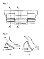
- Fig. 7 shows the position of the section lines AA and BB in the module section 3.
- FIGS. 8a . 9a, 10a and 11a the position of the lateral Flap area 30 and the FIGS. 8b . 9b, 10b and 11b reproduce the position of the middle flap area 29.
- FIGS. 8a and 8b the rear compartment door 19 is shown in a position in which cold air can neither reach the rear ventilator outlet 5 nor the rear footwell supply outlet 6. Only hot air W can get to these outlets 5 and 6.
- FIGS. 9a and 9b show a middle position of the rear compartment door 19, in which both cold air K and hot air W in the direction of the rear ventilation outlet 5 and Fondfußraummakerssauslass 6 is mixed flowing and exits there as mixed air M.
- FIGS 10a and 10b show the position of the rear compartment door 19, in which the lateral flap area 30 and the central flap area 29 prevent the supply of hot air to the rear ventilation outlet 5 and the rear foot space supply outlet 6.
- the rear guide surface 36 seals the hot air supply channel for the hot air W.
- the sealing takes place in particular by the rear guide surface 34 with the functional web 37. Only cold air K then reaches the rear ventilation outlet 5 and the rear foot space supply outlet 6.
- Fig. 11a and 11b represent the extreme position of the rear compartment door, in which any air supply, ie cold air supply K and hot air supply W, is shut off by the front guide surface and the rear guide surface 35 and 36 of the lateral flap region 30. At the same time only the hot air supply W is shut off by the front guide surface 33 and the rear guide surface 34 of the central flap region 29. From the Fondfußraummentssauslass 6 thus no longer air, whereas the maximum possible Kakluftmenge K exits from the rear ventilation aisle.
- any air supply ie cold air supply K and hot air supply W
Description
Die Erfindung betrifft eine Klimaanlage für ein Kraftfahrzeug mit einem Gehäuse, einer im Gehäuse angeordneten Heizvorrichtung, mehreren im Gehäuse ausgebildeten Luftkanälen, einen im Gehäuse ausgebildeten ersten Auslassbereich, zum Versorgen eines ersten Bereiches mit temperierter Luft, und einen im Gehäuse ausgebildeten zweiten Auslassbereich zum Versorgen eines zweiten Bereiches mit temperierter Luft.The invention relates to an air conditioning system for a motor vehicle having a housing, a heating device arranged in the housing, a plurality of air channels formed in the housing, a first outlet region formed in the housing, for supplying a first region with tempered air, and a second outlet region formed in the housing for supplying a second area with tempered air.
Aus dem Stand der Technik sind unterschiedliche Klimaanlagen für Kraftfahrzeuge bekannt. So offenbart etwa die
Auch aus der
Ähnliche Kraftfahrzeugklimaanlagen sind auch aus den Druckschriften
Die Klimaanlagen aus dem Stand der Technik erfordern zumeist viel Bauraum, kinematische Kopplungen für die zahlreichen Klappen und hohe Fertigungsaufwendungen für eine Temperatur- und Verteilungseinstellung bezüglich der Luftzufuhr in den Fondbereich des Kraftfahrzeuges.The air conditioners of the prior art usually require a lot of space, kinematic couplings for the numerous flaps and high production costs for a temperature and distribution adjustment with respect to the air supply in the rear region of the motor vehicle.
Die
Es ist die Aufgabe der Erfindung, eine weiter verbesserte Klimaanlage zur Verfügung zu stellen. Diese Aufgabe wird durch den Merkmalen des Anspruchs 1 gelöst. Bei der erfindungsgemäβen Klimaanlage wird eine einzige Fondraumklappe stromabwärts von der Heizvorrichtung zum Mischen von Warm- und Kaltluft sowie zum Verteilen der aus dem Fondfußraumversorgungsauslass und dem Fondbelüftungsauslass zu entlassenden Luft angeordnet. Unter "Verteilen" wird dabei auch ein "Leiten" verstanden.It is the object of the invention to provide a further improved air conditioning system. This object is solved by the features of
Durch eine derartige Ausgestaltung werden die bisher notwendigen Klappen vor und nach der Heizvorrichtung zum Vorsehen einerseits einer angemessen temperierten Luftmenge und andererseits zum Aufteilen dieser angemessen temperierten Luftmenge auf die jeweiligen Auslässe vermieden. Die Folge ist ein geringerer Bauraumbedarf durch eine kompaktere Bauweise. Ferner wird der Aufbau der Klimaanlage vereinfacht und so auch der Fertigungsaufwand verringert.By such a configuration, the previously necessary flaps before and after the heater for providing on the one hand a moderately tempered air quantity and on the other hand for dividing this appropriate tempered air flow to the respective outlets avoided. The result is a smaller space requirement through a more compact design. Furthermore, the structure of the air conditioner is simplified and thus reduces the production cost.
In den Unteransprüchen werden Ausführungsformen beansprucht und nachfolgend näher beschrieben, die besonders vorteilhaft sind.In the subclaims embodiments are claimed and described in more detail below, which are particularly advantageous.
In einer bevorzugten Ausführungsform weist die Klimaanlage in ihrem Gehäuse einen Verdampfer auf, der kalte Luft erzeugt, um die Innenraumtemperatur des Kraftfahrzeuges unter die Außenlufttemperatur zu senken. Dadurch ist eine gewünschte Klimatisierung mittels Kaltluft realisierbar.In a preferred embodiment, the air conditioner in its housing on an evaporator, which generates cold air to lower the interior temperature of the motor vehicle below the outside air temperature. As a result, a desired air conditioning by means of cold air can be realized.
Um ein Entkoppeln der in den Frontbereich geleiteten Luft von der in den . Fondbereich geleiteten Luft, insbesondere bezüglich der Temperatur, zu erreichen, ist es von Vorteil, einen Bypasskanal zum erwärmungslosen Vorbeiführen der Kaltluft an der Heizvorrichtung vorzusehen, der vorzugsweise unterhalb der Heizvorrichtung angeordnet ist. Durch das Anordnen des Bypasskanals unterhalb der Heizvorrichtung kann ein Schichten der Luft in Abhängigkeit von der Temperatur besonders gut erreicht werden.To decouple the guided into the front area of the air in the. It is advantageous to provide a bypass duct for the warming-free passage of the cold air past the heating device, which is preferably arranged below the heating device. By arranging the bypass channel below the heating device, a layering of the air as a function of the temperature can be achieved particularly well.
Unter dem Begriff "unterhalb" ist im Weiteren die Anordnung anzusehen in der die Klimaanlage in Bezug auf die Längsachse des Fahrzeuges verbaut ist. Im Weiteren wird davon ausgegangen, dass die Längsachse des Fahrzeuges parallel zu einer Längsachse durch die Klimaanlage angeordnet ist. Es ist jedoch auch möglich, dass die Längsachse der Klimaanlage quer zur Längsachse des Fahrzeuges ausgerichtet ist.The term "below" is to be regarded in the following, the arrangement in which the air conditioner is installed in relation to the longitudinal axis of the vehicle. In addition, it is assumed that the longitudinal axis of the vehicle is arranged parallel to a longitudinal axis through the air conditioning. However, it is also possible that the longitudinal axis of the air conditioning is aligned transversely to the longitudinal axis of the vehicle.
Die Heizvorrichtung ist erfindungsgemäβ von einem, eine Luftzufuhr zur Heizvorrichtung verhindernden Gehäuseabschnitt umgeben, der eine Öffnung stromaufwärts von der Heizvorrichtung aufweist, die durch eine Resterwärmungsklappe verschließbar ist. Ist diese Resterwärmungsklappe verschlossen, so ist durch den Nutzer des Kraftfahrzeuges eine maximale Kühlleistung abrufbar, ohne dass diese durch zwangsweise durch die Heizvorrichtung strömende und sich dabei erwärmende Luft gemindert wird.The heating device according to the invention is surrounded by a housing section which prevents an air supply to the heating device and has an opening upstream from the heater, which is closable by a Resterwärmungsklappe. If this Resterwärmungsklappe is closed, then the user of the motor vehicle, a maximum cooling capacity can be retrieved without this is mitigated by forcibly flowing through the heater and thereby warming air.
Vorzugsweise ist in dem Gehäuseabschnitt eine weitere stromaufwärts der Heizvorrichtung angeordnete Öffnung zum Hindurchleiten von Kaltluft zum zweiten Auslassbereich durch die Heizvorrichtung vorgesehen. Durch diese Öffnung kann eine Warmluftzufuhr in den Fondbereich unabhängig von der Warmluftzufuhr in den Frontbereich erfolgen.Preferably, an additional opening arranged upstream of the heating device for passing cold air to the second outlet region through the heating device is provided in the housing section. Through this opening, a hot air supply in the rear area regardless of the hot air supply in the front area.
Zur Vermeidung von großen Strömungsverlusten ist es von Vorteil, wenn die Fondraumklappe im unteren Bereich der Klimaanlage angeordnet ist, vorzugsweise auf Höhe der Unterkante der Heizvorrichtung.To avoid large flow losses, it is advantageous if the rear compartment door is arranged in the lower region of the air conditioning system, preferably at the level of the lower edge of the heating device.
Vorteilhaft ist es ferner, den Fondfußraumversorgungsauslass neben dem Fondbelüftungsauslass, bevorzugt beiderseits des Fondbelüftungsauslasses, weiter bevorzugt auf im Wesentlichen gleicher Höhe zum Fondbelüftungsauslass anzuordnen. Die temperierte Luft lässt sich so auf die rechte und linke Seite des Kraftfahrzeuges in den Fondfußraum leiten.It is also advantageous to arrange the rear footwell supply outlet in addition to the rear ventilating outlet, preferably on both sides of the rear ventilating outlet, more preferably at substantially the same height to the rear ventilating outlet. The tempered air can be directed to the right and left side of the vehicle in the rear footwell.
Zur Vermeidung von Strömungsverlusten und zur Vermeidung des ungewünschten Vermischens von unterschiedlich warmer Luft, ist es von Vorteil, die Fondraumklappe zu unterteilen. Dies erfolgt bevorzugt durch sich quer zur Drehachse der Fondraumklappe erstreckende Scheiben, die in einem mittleren Klappenbereich angeordnet sind und zwei sich außerhalb davon befindliche, seitliche Klappenbereiche. Diese Gestaltung verhindert ein Vermischen der über die seitlichen Klappenbereiche zu dem Fondfußraumversorgungsauslass geleiteten Luft mit der über den mittleren Klappenbereich geleiteten Luft.To avoid flow losses and to avoid the unwanted mixing of different warm air, it is advantageous to divide the rear compartment door. This is preferably done by extending transversely to the axis of rotation of the rear compartment door panes, which are arranged in a central flap area and two located outside thereof, lateral flap areas. This design prevents mixing over the side flap areas to the rear footwell supply outlet directed air with the over the middle flap area conducted air.
In einer Ausführungsform weist der mittlere Klappenbereich bevorzugt einen, am Rand der dem Fondbelüftungsauslass zugewandten Leitfläche veriaufenden Funktionssteg auf, welcher sich im Wesentlichen senkrecht davon und im Wesentlichen quer zur Richtung der Warmluftzufuhr erstreckt. Zur Einleitung eines maximalen Kaltluftstroms in den Fondraum verhindert dieser Funktionssteg eine Warmluftzufuhr zum Fondbelüftungsauslass, wodurch ausschließlich Kaltluft vom seitlichen Klappenbereich zu dem Fondfußraumversorgungsauslass gelangt. In einer weiteren bevorzugten Ausführungsform ist der Funktionssteg schalenförmig ausgeformt, insbesondere angepasst an die Außenkontur der sich quer zur Drehachse der Fondraumklappe erstreckenden Scheiben.In one embodiment, the middle flap region preferably has a functional web, which runs along the edge of the guide air vent facing the rear ventilating outlet and extends substantially perpendicularly therefrom and essentially transversely to the direction of the hot air supply. To initiate a maximum flow of cold air into the rear compartment, this function bar prevents a supply of hot air to the rear ventilation outlet, whereby only cold air from the side flap area reaches the rear footwell supply outlet. In a further preferred embodiment, the functional web is shaped like a shell, in particular adapted to the outer contour of the disks extending transversely to the axis of rotation of the rear compartment door.
Es wird allgemein als unangenehm empfunden, wenn die Füße stark gekühlt werden. Daher ist es von besonderem Vorteil, die Fondraumklappe so auszubilden und anzuordnen, dass in einer Extremstellung, in der ausschließlich Kaltluft zu dem Fondbelüftungsauslass gelangt, der seitliche Klappenbereich eine Luftzufuhr zu dem Fondfußraumversorgungsauslass verhindert.It is generally considered uncomfortable when the feet are strongly cooled. Therefore, it is particularly advantageous to design and arrange the rear compartment door in such a way that, in an extreme position in which only cold air reaches the rear ventilating outlet, the lateral flap area prevents air from being supplied to the rear footwell supply outlet.
Besonders effizient und einfach lässt sich dies realisieren, wenn der seitliche Klappenbereich den Fußraumversorgungsauslass verschließt.This can be implemented particularly efficiently and simply if the lateral flap area closes the footwell supply outlet.
Vorzugsweise wird besonders kostengünstig ein zwangsgekoppeltes Stellelement realisiert, wenn der mittlere und seitliche Klappenbereich der Fondraumklappe sowie die Scheiben aus einem integralen Bauteil bestehen. Dieses Bauteil umfasst bevorzugt auch eine Welle, durch welche die Drehachse der Fondraumklappe verläuft. Bei einer solchen Ausführung erfolgtPreferably, a positively coupled actuator is realized particularly cost if the middle and side flap area of the rear compartment door and the discs consist of an integral component. This component preferably also includes a shaft through which passes the axis of rotation of the rear compartment door. In such an embodiment takes place
nur eine geringe Vermischung der den unterschiedlichen Bereichen zugeführten Luftmengen.only a slight mixing of the amounts of air supplied to the different areas.
In einer bevorzugt Ausführungsform ist das Gehäuse entlang einer Ebene, in der seine Längsachse verläuft, zweigeteilt. Hierdurch wird eine besonders einfache und schnelle Montierbarkeit des Gehäuses erreicht.In a preferred embodiment, the housing is divided into two along a plane in which its longitudinal axis runs. As a result, a particularly simple and quick mountability of the housing is achieved.
Zur Vermeidung einer ungewollten Erwärmung des Kraftfahrzeug-Innenraums ist in einer bevorzugten Ausführungsform zwischen der Resterwärmungsklappe und dem Gehäuseabschnitt eine Dichteinrichtung angeordnet.To avoid unwanted heating of the motor vehicle interior, a sealing device is arranged in a preferred embodiment between the Resterwärmungsklappe and the housing portion.
Vorzugsweise ist die Resterwärmungsklappe mit einer Temperaturkinematik des Fondbereiches, also des ersten Auslassbereiches gekoppelt. In diesem Fall kann ein zusätzliches Betätigungselement entfallen. Eine unabhängige Regelung der drei Sektionen ist dann nicht möglich.Preferably, the Resterwärmungsklappe is coupled with a temperature kinematics of the rear region, ie the first outlet area. In this case, an additional actuator can be omitted. An independent regulation of the three sections is then not possible.
Eine symmetrische Aufteilung zum unabhängigen Regeln von vier Zonen ist ebenfälls realisierbar.A symmetrical distribution for independent regulation of four zones is just as feasible.
Für eine Montage der einzelnen Komponenten ist es ferner von Vorteil, wenn das Gehäuse einen Modulabschnitt aufweist, in dem der Fondfußraumversorgungslass, der Fondbelüftungsauslass und die Fondraumklappe angeordnet sind.For mounting the individual components, it is also advantageous if the housing has a module section in which the rear footwell supply outlet, the rear ventilation outlet and the rear compartment flap are arranged.
Wird die Klimaanlage in einem Fahrzeug untergebracht, in dem kein Fondraum vorhanden ist oder die Belüftung des Fondraums ungewünscht ist, so lässt sich vorteilhafter Weise der Bereich, in dem der Modulabschnitt anzuordnen ist, durch eine Platte kostengünstig verschließen oder die Öffnung einfach mittels Verspritzens verschließen.If the air conditioner is housed in a vehicle in which no rear space is present or the ventilation of the rear compartment is undesirable, then advantageously the area in which the module section is to be arranged, cost-effectively close by a plate or close the opening simply by spraying.
Diese Erfindung wird anhand eines Ausführungsbeispieles mit Hilfe einer Zeichnung näher erläuternt. Dabei zeigen:
- Fig. 1
- eine schematische Ansicht auf eine Klimaanlage mit einem Gehäuse in perspektivischer Ansicht parallel zur Längsachse des Gehäuses,
- Fig. 2
- eine schematische Querschnittsansicht durch die Klimaanlage entlang der Linie II aus
Fig. 1 , - Fig. 3
- eine schematische perspektivische Darstellung eines beispielhaften Modulabschnitts des Gehäuses der Klimaanlage aus Sicht des Fondbereiches, versetzt zur Längsachse des Gehäuses,
- Fig. 4
- eine schematische perspektivische Darstellung des Modulabschnittes des Gehäuses der Klimaanlage in Richtung des Fondbereiches, versetzt zur Längsachse des Gehäuses,
- Fig. 5
- eine schematische perspektivische Darstellung einer Fondraumklappe, die in dem Modulabschnitt angeordnet ist,
- Fig. 6a
- eine schematische perspektivische Darstellung eines rechten Teiles des Modulabschnittes des Gehäuses der Klimaanlage, wobei die Fondraumklappe nicht eingesetzt ist,
- Fig. 6b
- eine schematische perspektivische Darstellung des rechten Teiles des Modulabschnittes des Gehäuses der Klimaanlage aus
Fig. 6a , wobei die Fondraumklappe im eingesetzten Zustand gestrichelt dargestellt ist, - Fig. 7
- eine Ansicht des Modulabschnittes aus Sicht des Fondbereiches, in der die Position der Schnittebenen, wie sie in den
Figuren 8 bis 11 angegeben sind, dargestellt ist, - Fig. 8a
- eine schematische Schnittdarstellung entlang der Ebene A-A aus
Fig. 7 , wobei die Fondraumklappe eine Stellung einnimmt, in der ausschließlich Warmluft in den Fondfußraum gelangt und Warmluft zum Beheizen des Fondbelüftungsraumes genutzt wird, - Fig. 8b
- eine schematische Schnittdarstellung entlang der Ebene B-B aus
Fig. 7 durch den Modulabschnitt und die Fondraumklappe, wobei die Fondraumklappe dieselbe Stellung einnimmt wie inFig. 8a , - Fig. 9a
- eine Mischstellung der Fondraumklappe im Schnitt entlang der Ebene A-A aus
Fig. 7 , in einer Stellung der Fondraumklappe in der sich Warm- und Kaltluft vermischen, - Fig. 9b
- eine schematische Schnittdarstellung entlang der Ebene B-B aus
Fig. 7 durch den Modulabschnitt und die Fondraumklappe, wobei die Fondraumklappe dieselbe Stellung einnimmt, wie die inFig. 9a dargestellte Klappe, so dass sich auch im Fondbelüftungsbereich Warm- und Kaltluft mischen, - Fig. 10a
- eine Schnittdarstellung entlang der Ebene A-A aus
Fig. 7 , die die Fondraumklappe in einer Stellung darstellt, in der lediglich Kaltluft in den Fondfußraumbereich gelangt, - Fig. 10b
- einen Schnitt entlang der Ebene B-B aus
Fig. 7 , wobei die Fondraumklappe dieselbe Stellung einnimmt, wie inFig. 10a , so dass aufgrund der verschließenden Wirkung eines Funktionssteges auf der Fondraumklappe, der im mittleren Klappenbereich angeordnet ist, lediglich Kaltluft in den Fondbelüftungsbereich geführt wird, - Fig. 11a
- einen Schnitt durch den Modulabschnitt und die Fondraumklappe entlang der Linie A-A aus
Fig. 7 , wobei die Fondraumklappe in einer Extremstellung positioniert ist, in der ein seitlicher Klappenbereich den Fondfußraumversorgungsauslass von Kaltluftzufuhr und Warmluftzufuhr abtrennt und - Fig. 11b
- eine schematische Schnittdarstellung durch den Modulabschnitt und die Fondraumklappe entlang der Ebene B-B aus
Fig. 7 , wobei die Fondraumklappe in derselben Stellung befindlich ist, wie inFig. 11a , so dass lediglich Kaltluft in den Fondbelüftungsbereich gelangen kann.
- Fig. 1
- a schematic view of an air conditioner with a housing in a perspective view parallel to the longitudinal axis of the housing,
- Fig. 2
- a schematic cross-sectional view through the air conditioning along the line II
Fig. 1 . - Fig. 3
- a schematic perspective view of an exemplary module portion of the housing of the air conditioner from the perspective of the rear area, offset to the longitudinal axis of the housing,
- Fig. 4
- a schematic perspective view of the module portion of the housing of the air conditioning in the direction of the rear region, offset to the longitudinal axis of the housing,
- Fig. 5
- a schematic perspective view of a rear compartment door, which is arranged in the module section,
- Fig. 6a
- a schematic perspective view of a right part of the module portion of the housing of the air conditioner, wherein the rear compartment door is not inserted,
- Fig. 6b
- a schematic perspective view of the right part of the module portion of the housing of the air conditioner
Fig. 6a , wherein the rear compartment flap is shown in dashed lines in the inserted state, - Fig. 7
- a view of the module section from the perspective of the rear area, in which the position of the cutting planes, as in the
FIGS. 8 to 11 are shown, is shown - Fig. 8a
- a schematic sectional view taken along the plane AA
Fig. 7 in which the rear compartment flap assumes a position in which only warm air enters the rear footwell and warm air is used for heating the rear ventilating compartment, - Fig. 8b
- a schematic sectional view taken along the plane BB
Fig. 7 through the module section and the rear compartment door, wherein the rear compartment door occupies the same position as inFig. 8a . - Fig. 9a
- a mixed position of the rear compartment flap in section along the AA level
Fig. 7 , in a position of the rear compartment door in which hot and cold air mix, - Fig. 9b
- a schematic sectional view taken along the plane BB
Fig. 7 through the module section and the rear compartment door, wherein the rear compartment door occupies the same position as inFig. 9a shown flap, so that also mix in the rear ventilation area hot and cold air, - Fig. 10a
- a sectional view taken along the plane AA
Fig. 7 that represents the rear compartment door in a position in which only cold air enters the rear footwell area, - Fig. 10b
- a section along the plane BB
Fig. 7 , wherein the rear compartment door occupies the same position as inFig. 10a , so that due to the occlusive effect of a functional bridge on the rear compartment door, which is arranged in the middle flap area, only cold air is fed into the rear ventilation area, - Fig. 11a
- a section through the module section and the rear compartment door along the line AA
Fig. 7 wherein the rear compartment door is positioned in an extreme position in which a side flap portion separates the rear footwell supply outlet from cold air supply and hot air supply, and - Fig. 11b
- a schematic sectional view through the module section and the rear compartment door along the plane BB
Fig. 7 , wherein the rear compartment door is in the same position as inFig. 11a , so that only cold air can enter the rear ventilation area.
In
An einem, dem restlichen Gehäuse 2 abgewandten, entfernten Ende des Modulabschnitts 3 ist ein Fondbelüftungsauslass 5 ansatzweise kanalförmig ausgebildet.At a remote from the rest of the
In
Wird keine Dichteinrichtung verwendet, so dient die Resterwärmungsklappe 11 lediglich als Leitelement. In diesem Fall kann ein Leckluftstrom auftreten, der in bestimmten Ausführungen auch gewollt ist. Auch bei geschlossener Resterwärmungsklappe 11 kann dann Luft über die Randbereiche der Resterwärmungsklappe 11 zur Heizvorrichtung 7 gelangen.If no sealing device is used, then the heat-up flap 11 merely serves as a guide element. In this case, a leakage air flow may occur, which is also wanted in certain embodiments. Even with the restraint flap 11 closed, air can then reach the
Unterhalb der ersten Öffnung, die durch die Resterwärmungsklappe 11 verschließbar ist, ist hingegen zweite Öffnung 10 erfindungsgemäβ nicht durch eine Klappe verschließbar ausgeführt. Somit gelangt im unteren Bereich der Heizvonichtung 7 immer Luft durch die zweite Öffnung 10 hindurch zur Heizvorrichtung 7. Diese wird dort erwärmt und tritt nachfolgend im unteren Bereich der Klimaanlage 1 aus der Heizvorrichtung 7 aus.On the other hand, below the first opening, which can be closed by the heat-up flap 11, the
Die Klimaanlage 1 mit dem Gehäuse 2 ist so strukturiert, dass zwei voneinander trennbare Auslassbereiche 12 und 13 vorliegen. Der erste Auslassbereich 12 ist oberhalb des zweiten Auslassbereiches 13 angeordnet. Eine Temperaturklappe 14 trennt den ersten Auslassbereich 12 vom zweiten Auslassbereich 13.The
In dem Gehäuse 2 ist auch ein Verdampfer 15 vorgesehen, der mit Frischluft L beaufschlagt wird. Die Frischluft L wird beim Durchtreten durch den Verdampfer gekühlt, so dass sie als Kaltluft K bezeichnet wird. Die Kaltluft K kann ohne Erwärmung bei Durchtritt durch zwei Öffnungen in den ersten Auslassbereich 12 gelangen. Diese zwei Öffnungen sind durch Temperaturklappen 16 und 17 verschließbar. Alternativ kann die Kaltluft auch durch die erste Öffnung 9 zur Heizvorrichtung 7 gelangen, dort erwärmt werden und bei geöffneter Temperaturklappe 14 in den ersten Auslassbereich 12 gelangen.In the
Es ist ferner möglich, eine Mischung der Kaltluft K, die durch die mittels der Temperaturklappen 16 und 17 verschließbare Öffnung hineingelangende Kaltluft mit der durch die Temperaturklappe 14 verschließbare Öffnung hineingelangende Warmluft W, vorzunehmen. Eine entsprechend temperierte Luft verlässt dann bei Öffnung entsprechender Regelelemente den ersten Auslassbereich 12 durch so genannte Entfrosterdüsen, Mittelkonsolenbelüftungsdüsen und/ oder Fußraumbelüftungsdüsen. Die Luft, die aus dem ersten Auslassbereich entlassen wird, beaufschlagt den Fahrer- und/ oder Passagierraum im Vorderbereich des Fahrzeugs.It is also possible to make a mixture of the cold air K, which passes through the opening by means of the
Es ist möglich, die Klimaanlage 1 und insbesondere das Gehäuse 2 derart zweiteilig auszugestalten, dass eine Temperaturregelung auf der Fahrer - und Beifahrerseite im Frontbereich des Fahrzeuges unabhängig voneinander möglich ist.It is possible to configure the
Die durch die erste Öffnung hindurch gelangende Kaltluft oder die durch die zweite Öffnung 10 hindurch gelangende Kaltluft wird durch die Heizvorrichtung 7 und/ oder den PTC-Zuheizer 8 erwärmt und gelangt dadurch in den zweiten Auslassbereich 13. Die erhaltene Warmluft W kann alternativ auch als Heiß- oder Heizluft bezeichnet werden.The cold air passing through the first opening or the cold air passing through the
Unterhalb des die Heizvorrichtung 7 aufnehmenden Gehäuseabschnittes des Gehäuses 2 ist ein Bypasskanal 18 ausgeformt. Durch den Bypasskanal 18 gelangt lediglich Kaltluft K, die aufgrund der durch das Gehäuse 2 vorgegebenen Trennung zu der Heizvorrichtung 7 und dem PTC-Zuheizer 8 nicht direkt erwärmt wird. Diese Kaltluft wird in Richtung des zweiten Auslassbereiches 13 geleitet. Am entfernten Ende des zweiten Auslassbereiches 13 ist der Modulabschnitt 3 angebunden. Der Modulabschnitt 3 ist mit dem Gehäuse 2 entweder integral verbunden ausgeführt, verklebt, verspritzt oder auf sonstige Weise verbunden, Im Übergangsbereich des Gehäuses 2 zum Modulabschnitt 3 ist allerdings das Austreten von Luft baulich verhindert.Below the
Der Modulabschnitt 3 weist eine Fondraumklappe 19 auf. Die Fondraumklappe 19 erstreckt sich durch einen Fondversorgungsbereich 20. Kalt- und/oder Warmluft, die in den Fondversorgungsbereich 20 gelangt, wird über den Fondbelüftungsauslass 5 oder die beiden Fondfußraumversorgungsauslässe 6 in den Fondfußraum, einmal auf die linke Seite des Kraftfahrzeuges und einmal auf die rechte Seite des Kraftfahrzeuges, sowie in einen oberhalb des Fondfußraums befindlichen Bereich, der als Fondbelüftungsbereich bezeichnet wird, geleitetThe
In
In
In
Es ist möglich, dass der Modulabschnitt 3 eine Trennebene mittig im Fondbelüftungsauslass 5 und durch die Fondbelüftungskalt- und -warmluftbereiche 26, 27 hindurchragend ausbildet, so dass der gesamte Fondbereich in eine linke und rechte Seite unterteilt und mit unterschiedlich temperierter Luft beaufschlagbar ist. Derart lässt sich eine so genannte 4-Zonen-Regelung im Kraftfahrzeuginneren realisieren.It is possible for the
Es wäre dabei von Vorteil, die Fondraumklappe 19 in eine rechte und linke Hälfte zu trennen, so dass beide Hälften der Fondraumklappe unabhängig voneinander bedienbar wären. Hierfür sind jedoch zusätzliche Betätigungselemente erforderlich.It would be advantageous to separate the
In
Beiderseits der Welle 28 weist der mittlere Klappenbereich 29 eine vordere Leitfläche 33 und eine hintere Leitfläche 34 auf. Die seitlichen Klappenbereiche 30 weisen ebenfalls beiderseits der Welle 28 eine vordere Leitfläche 35 und eine hintere Leitfläche 36 auf. Die vordere Leitfläche 33 und die hintere Leitfläche 34 liegen nicht in ein und derselben Ebene. Auch die vordere Leitfläche 35 und die hintere Leitfläche 36 liegen nicht in ein und derselben Ebene. Die Leitflächen 33 bis 36 liegen in jeweils eigenen Ebenen, die nicht deckungsgleich zu den jeweils anderen drei Ebenen liegen. Die Ebenen der Leitflächen 33 bis 36 sind so an der Fondraumklappe 19 angeordnet, dass sie sich jeweils im Bereich der Drehachse 23 schneiden.On both sides of the
Die hintere Leitfläche 34, also die Leitfläche, die dem Fondbelüftungsauslass 5 am nächsten ist, weist einen Funktionssteg 37 auf. Der Funktionssteg 37 steht senkrecht auf der hinteren Leitfläche 34.The
In den
In den
Die
Die
Die
Claims (13)
- An air conditioner (1) for a motor vehicle, comprising a heating device (7) that is arranged in the housing (2), a plurality of air ducts that are formed in the housing (2), a first outlet region (12) that is formed in the housing (2), and a second outlet region (13) that is formed in the housing (2), wherein the second outlet region (13) is divided into at least one rear footwell supply outlet (6) and at least one rear ventilation outlet (5), wherein a single rear space damper door (19) is arranged downstream of the heating device (7) for mixing warm and cold air and for distributing the air that is to be discharged from the at least one rear footwell supply outlet (6) and the at least one rear ventilation outlet (5), and wherein the heating device is surrounded by a housing section preventing air from being supplied to the heating device (7), the housing section upstream of the heating device (7) having a first opening (9), which can be closed by a residual heating flap (11), and a further second opening (10), which is arranged in the housing section upstream of the heating device (7) for conducting cold air through to the second outlet region (13) by the heating device (7), wherein the second opening (10) is arranged beneath the first opening (9), characterized in that the second opening cannot be closed by a flap.
- The air conditioner (1) according to claim 1, comprising an evaporator (15), which generates cold air, in the housing (2).
- The air conditioner (1) according to claim 1 or 2, wherein a bypass duct (18) is provided so as to conduct the cold air (K) past the heating device (7) without heating this air.
- An air conditioner (1) according to any one of claims 1 to 3, wherein the rear space damper door (19) is arranged in the lower region of the air conditioner (1), preferably at the level of the lower edge of the heating device (7).
- An air conditioner (1) according to any one of claims 1 to 4, wherein the rear footwell supply outlet (6) is arranged next to the rear ventilation outlet (5), preferably on both sides of the rear ventilation outlet (5), and also preferably essentially at the same level as the rear ventilation outlet (5).
- An air conditioner (1) according to any one of claims 1 to 5, wherein the rear space damper door (19) is divided by disks (31, 32), which extend transversely relative to the rotational axis of the rear space damper door (19), into a center damper door region (29) and two lateral damper door regions (30) located outside thereof.
- The air conditioner (1) according to claim 6, wherein the center damper door region (29) comprises a functional web (37) running at the edge of the guide surface that faces the rear ventilation outlet (5), this functional web extending essentially perpendicularly relative to the damper door region and essentially transversely relative to the direction of the warm air supply.
- The air conditioner (1) according to claim 6 or 7, wherein the rear space damper door (19) is designed and arranged so that, in an extreme position in which only cold air (K) can reach the rear ventilation outlet (5), the lateral damper door region (30) prevents air from being supplied to the rear footwell supply outlet (6).
- The air conditioner (1) according to claim 8, wherein the lateral damper door region (30) closes the rear footwell supply outlet (6).
- An air conditioner (1) according to any one of claims 6 to 9, wherein the center and the lateral damper door regions (30) of the rear space damper door (19) and the disks (31, 32) are made of an integral component, which also comprises a shaft (28), through which the rotational axis (23) of the rear space damper door (19) extends.
- An air conditioner (1) according to any one of claims 1 to 10, wherein the housing (2) is divided into two parts along a plane, in which the longitudinal axis (4) of the housing (2) runs.
- An air conditioner (1) according to any one of claims 1 to 11, wherein a sealing element is arranged between the residual heating flap (11) and the housing section.
- An air conditioner (1) according to any one of claims 1 to 12, wherein the housing (2) comprises a module section (3), in which the rear footwell supply outlet (6), the rear ventilation outlet (5) and the rear space damper door (19) are arranged.
Applications Claiming Priority (1)
| Application Number | Priority Date | Filing Date | Title |
|---|---|---|---|
| DE102007041689A DE102007041689A1 (en) | 2007-09-03 | 2007-09-03 | Air conditioning system for a motor vehicle with a rear compartment flap for mixing and distributing the air |
Publications (3)
| Publication Number | Publication Date |
|---|---|
| EP2030816A2 EP2030816A2 (en) | 2009-03-04 |
| EP2030816A3 EP2030816A3 (en) | 2010-06-30 |
| EP2030816B1 true EP2030816B1 (en) | 2013-05-22 |
Family
ID=39798183
Family Applications (1)
| Application Number | Title | Priority Date | Filing Date |
|---|---|---|---|
| EP20080015377 Expired - Fee Related EP2030816B1 (en) | 2007-09-03 | 2008-09-01 | Vehicle air conditioner with a rear space damper door for mixing and distributing air |
Country Status (2)
| Country | Link |
|---|---|
| EP (1) | EP2030816B1 (en) |
| DE (1) | DE102007041689A1 (en) |
Families Citing this family (6)
| Publication number | Priority date | Publication date | Assignee | Title |
|---|---|---|---|---|
| US9724978B2 (en) * | 2015-04-14 | 2017-08-08 | Mahle International Gmbh | HVAC module having an open architecture |
| US9879870B2 (en) | 2015-04-14 | 2018-01-30 | Mahle International Gmbh | HVAC module with anti-backflow control and method of operation |
| EP3144166B1 (en) * | 2015-09-15 | 2019-07-17 | Mahle International GmbH | Hvac module with anti-backflow control and method of operation |
| DE102019128461A1 (en) * | 2019-10-22 | 2021-04-22 | Mann+Hummel Gmbh | Flow system for fluids with a switching device |
| CN112124039A (en) * | 2020-10-20 | 2020-12-25 | 上海爱斯达克汽车空调系统有限公司 | Air inlet device of automobile air conditioner |
| EP4219200A1 (en) * | 2022-02-01 | 2023-08-02 | Valeo Klimasysteme GmbH | Ventilation, heating and/or air conditioning device |
Family Cites Families (14)
| Publication number | Priority date | Publication date | Assignee | Title |
|---|---|---|---|---|
| SE8001514L (en) | 1980-02-27 | 1981-08-28 | Saab Scania Ab | VEHICLE HEATING AND VENTILATION SYSTEM |
| FR2726229B1 (en) | 1994-10-28 | 1996-12-13 | Valeo Thermique Habitacle | HEATING AND / OR VENTILATION DEVICE FOR THE INTERIOR OF A MOTOR VEHICLE |
| KR100294482B1 (en) * | 1996-07-27 | 2001-10-24 | 신영주 | case of air conditioning system and air conditioning system utilzing the same |
| FR2778152B1 (en) | 1998-04-30 | 2000-06-30 | Valeo Climatisation | INSTALLATION FOR HEATING, VENTILATION AND / OR AIR CONDITIONING OF A COCKPIT, ESPECIALLY A MOTOR VEHICLE, WITH ZONE TEMPERATURE ADJUSTMENT |
| FR2795683B1 (en) | 1999-06-30 | 2002-06-14 | Valeo Climatisation | DEVICE FOR HEATING AND / OR AIR CONDITIONING A COCKPIT, ESPECIALLY A MOTOR VEHICLE, WITH TRANSVERSE DUCT |
| FR2795684B1 (en) | 1999-06-30 | 2002-06-21 | Valeo Climatisation | IMPROVED DEVICE FOR HEATING, VENTILATION AND / OR AIR CONDITIONING OF A COCKPIT, ESPECIALLY A MOTOR VEHICLE, WITH ZONE TEMPERATURE ADJUSTMENT |
| FR2798322B1 (en) * | 1999-09-10 | 2002-09-27 | Valeo Climatisation | AUTOMOTIVE VEHICLE HEATING AND / OR AIR CONDITIONING DEVICE WITH IMPROVED DISTRIBUTION |
| ITTO20010036A1 (en) | 2001-01-19 | 2002-07-19 | Magneti Marelli Climat Srl | GROUP FOR THE TREATMENT AND DISTRIBUTION OF AIR IN THE CABIN OF A VEHICLE. |
| US6772833B2 (en) | 2002-07-23 | 2004-08-10 | Visteon Global Technologies, Inc. | HVAC system with modular inserts |
| JP3952919B2 (en) * | 2002-09-17 | 2007-08-01 | 株式会社デンソー | Air conditioner for vehicles |
| JP4085769B2 (en) * | 2002-10-11 | 2008-05-14 | 株式会社デンソー | Air conditioner for vehicles |
| FR2862911B1 (en) | 2003-11-28 | 2006-03-03 | Valeo Climatisation | DEVICE FOR HEATING-VENTILATION AND / OR AIR CONDITIONING OF A VEHICLE HABITACLE WITH ZONE TEMPERATURE ADJUSTMENT |
| US8474513B2 (en) * | 2004-06-24 | 2013-07-02 | Behr Gmbh & Co. Kg | Air-conditioning system, especially automotive air-conditioning system |
| DE502004005568D1 (en) | 2004-09-10 | 2008-01-03 | Behr France Rouffach Sas | Modular automotive air conditioning system |
-
2007
- 2007-09-03 DE DE102007041689A patent/DE102007041689A1/en not_active Withdrawn
-
2008
- 2008-09-01 EP EP20080015377 patent/EP2030816B1/en not_active Expired - Fee Related
Also Published As
| Publication number | Publication date |
|---|---|
| EP2030816A3 (en) | 2010-06-30 |
| DE102007041689A1 (en) | 2009-03-05 |
| EP2030816A2 (en) | 2009-03-04 |
Similar Documents
| Publication | Publication Date | Title |
|---|---|---|
| EP1902876B1 (en) | Air distribution case, in particular for a vehicle air conditioner, having a distribution valve and method of controlling such a distribution valve | |
| EP1761406B1 (en) | Air-conditioning system, especially automotive air-conditioning system | |
| EP2030816B1 (en) | Vehicle air conditioner with a rear space damper door for mixing and distributing air | |
| WO2006027219A2 (en) | Modular motor vehicle air-conditioning unit | |
| DE102015110481A1 (en) | Device for heating, ventilating and / or conditioning a vehicle interior | |
| DE19804287C1 (en) | Air conditioner for motor vehicle interior | |
| EP1761405B1 (en) | Air-conditioning system, especially automotive air-conditioning system | |
| EP1306241B2 (en) | Motor vehicle heating and air conditioning system with combined air mixing and distributing damper door | |
| EP1641642A1 (en) | Louvre for an air-conduction housing of a vehicle air-conditioning system | |
| EP2048010B1 (en) | Vehicle air conditioning system | |
| EP2011675B1 (en) | Air conditioner | |
| DE102004056814B4 (en) | air conditioning | |
| EP1319537B1 (en) | Heating or air conditioning installation for motor vehicles | |
| DE102006027996A1 (en) | Air conditioning system, especially for motor vehicles, has a control flap at the end of the cold air bypass dividing the cold air into part-flows when fully open for mixing with the warm air | |
| DE19756166B4 (en) | Air duct for a heating or air conditioning system of a motor vehicle and thus equipped heating or air conditioning | |
| DE102004030672B4 (en) | V-shaped heat exchanger arrangement of a heating air conditioning | |
| EP1571019B1 (en) | Air conditioning device, in particular for a motor vehicle | |
| EP1733904B1 (en) | Air conditioning unit for a vehicle comprising a cold-air bypass | |
| EP1972473B1 (en) | Air conditioning system for a motor vehicle | |
| EP1792761B1 (en) | Flap assembly | |
| EP1531067B1 (en) | Air conditioning system in particular for a motor vehicle | |
| EP1555148B1 (en) | Air conditioning device, in particular for a vehicle | |
| EP1319538B1 (en) | Heating or air conditioning installation for motor vehicles | |
| DE102021209994A1 (en) | Air conditioning system of a motor vehicle | |
| DE102006027995A1 (en) | Air conditioning system, especially for motor vehicles, has a control flap at the end of the cold air bypass dividing the cold air into part-flows when fully open for mixing with the warm air |
Legal Events
| Date | Code | Title | Description |
|---|---|---|---|
| PUAI | Public reference made under article 153(3) epc to a published international application that has entered the european phase |
Free format text: ORIGINAL CODE: 0009012 |
|
| AK | Designated contracting states |
Kind code of ref document: A2 Designated state(s): AT BE BG CH CY CZ DE DK EE ES FI FR GB GR HR HU IE IS IT LI LT LU LV MC MT NL NO PL PT RO SE SI SK TR |
|
| AX | Request for extension of the european patent |
Extension state: AL BA MK RS |
|
| PUAL | Search report despatched |
Free format text: ORIGINAL CODE: 0009013 |
|
| AK | Designated contracting states |
Kind code of ref document: A3 Designated state(s): AT BE BG CH CY CZ DE DK EE ES FI FR GB GR HR HU IE IS IT LI LT LU LV MC MT NL NO PL PT RO SE SI SK TR |
|
| AX | Request for extension of the european patent |
Extension state: AL BA MK RS |
|
| 17P | Request for examination filed |
Effective date: 20101230 |
|
| AKX | Designation fees paid |
Designated state(s): DE FR GB |
|
| 17Q | First examination report despatched |
Effective date: 20111223 |
|
| GRAP | Despatch of communication of intention to grant a patent |
Free format text: ORIGINAL CODE: EPIDOSNIGR1 |
|
| GRAS | Grant fee paid |
Free format text: ORIGINAL CODE: EPIDOSNIGR3 |
|
| GRAA | (expected) grant |
Free format text: ORIGINAL CODE: 0009210 |
|
| AK | Designated contracting states |
Kind code of ref document: B1 Designated state(s): DE FR GB |
|
| REG | Reference to a national code |
Ref country code: GB Ref legal event code: FG4D Free format text: NOT ENGLISH |
|
| RIN1 | Information on inventor provided before grant (corrected) |
Inventor name: OTZELBERGER, NORBERT Inventor name: LINDAUER, SASCHA Inventor name: BURKHARDT, CARSTEN Inventor name: SCHWEIZER, GEBHARD |
|
| REG | Reference to a national code |
Ref country code: DE Ref legal event code: R096 Ref document number: 502008009963 Country of ref document: DE Effective date: 20130718 |
|
| PLBE | No opposition filed within time limit |
Free format text: ORIGINAL CODE: 0009261 |
|
| STAA | Information on the status of an ep patent application or granted ep patent |
Free format text: STATUS: NO OPPOSITION FILED WITHIN TIME LIMIT |
|
| 26N | No opposition filed |
Effective date: 20140225 |
|
| GBPC | Gb: european patent ceased through non-payment of renewal fee |
Effective date: 20130901 |
|
| REG | Reference to a national code |
Ref country code: DE Ref legal event code: R097 Ref document number: 502008009963 Country of ref document: DE Effective date: 20140225 |
|
| PG25 | Lapsed in a contracting state [announced via postgrant information from national office to epo] |
Ref country code: GB Free format text: LAPSE BECAUSE OF NON-PAYMENT OF DUE FEES Effective date: 20130901 |
|
| REG | Reference to a national code |
Ref country code: DE Ref legal event code: R082 Ref document number: 502008009963 Country of ref document: DE Representative=s name: GRAUEL, ANDREAS, DIPL.-PHYS. DR. RER. NAT., DE |
|
| REG | Reference to a national code |
Ref country code: DE Ref legal event code: R081 Ref document number: 502008009963 Country of ref document: DE Owner name: MAHLE INTERNATIONAL GMBH, DE Free format text: FORMER OWNER: BEHR GMBH & CO. KG, 70469 STUTTGART, DE Effective date: 20150323 Ref country code: DE Ref legal event code: R082 Ref document number: 502008009963 Country of ref document: DE Representative=s name: GRAUEL, ANDREAS, DIPL.-PHYS. DR. RER. NAT., DE Effective date: 20150323 |
|
| REG | Reference to a national code |
Ref country code: FR Ref legal event code: PLFP Year of fee payment: 9 |
|
| REG | Reference to a national code |
Ref country code: FR Ref legal event code: PLFP Year of fee payment: 10 |
|
| REG | Reference to a national code |
Ref country code: FR Ref legal event code: PLFP Year of fee payment: 11 |
|
| PGFP | Annual fee paid to national office [announced via postgrant information from national office to epo] |
Ref country code: DE Payment date: 20181001 Year of fee payment: 11 |
|
| PGFP | Annual fee paid to national office [announced via postgrant information from national office to epo] |
Ref country code: FR Payment date: 20190925 Year of fee payment: 12 |
|
| REG | Reference to a national code |
Ref country code: DE Ref legal event code: R119 Ref document number: 502008009963 Country of ref document: DE |
|
| PG25 | Lapsed in a contracting state [announced via postgrant information from national office to epo] |
Ref country code: DE Free format text: LAPSE BECAUSE OF NON-PAYMENT OF DUE FEES Effective date: 20200401 |
|
| PG25 | Lapsed in a contracting state [announced via postgrant information from national office to epo] |
Ref country code: FR Free format text: LAPSE BECAUSE OF NON-PAYMENT OF DUE FEES Effective date: 20200930 |