EP2030499A2 - Towed swather - Google Patents
Towed swather Download PDFInfo
- Publication number
- EP2030499A2 EP2030499A2 EP08167728A EP08167728A EP2030499A2 EP 2030499 A2 EP2030499 A2 EP 2030499A2 EP 08167728 A EP08167728 A EP 08167728A EP 08167728 A EP08167728 A EP 08167728A EP 2030499 A2 EP2030499 A2 EP 2030499A2
- Authority
- EP
- European Patent Office
- Prior art keywords
- swather
- tractor
- work units
- carrier frame
- support wheels
- Prior art date
- Legal status (The legal status is an assumption and is not a legal conclusion. Google has not performed a legal analysis and makes no representation as to the accuracy of the status listed.)
- Granted
Links
- 239000000463 material Substances 0.000 claims abstract description 17
- 244000025254 Cannabis sativa Species 0.000 claims abstract description 10
- 238000003306 harvesting Methods 0.000 claims abstract description 8
- 238000009313 farming Methods 0.000 claims abstract description 5
- 239000010902 straw Substances 0.000 claims abstract description 3
- 238000006073 displacement reaction Methods 0.000 claims 3
- 230000007246 mechanism Effects 0.000 description 8
- 238000001035 drying Methods 0.000 description 4
- 241000283690 Bos taurus Species 0.000 description 3
- 230000008901 benefit Effects 0.000 description 3
- 210000003608 fece Anatomy 0.000 description 3
- 239000010871 livestock manure Substances 0.000 description 3
- 238000011109 contamination Methods 0.000 description 2
- 239000003337 fertilizer Substances 0.000 description 2
- 239000004461 grass silage Substances 0.000 description 2
- 239000004460 silage Substances 0.000 description 2
- 239000002689 soil Substances 0.000 description 2
- 230000007480 spreading Effects 0.000 description 2
- 241001494496 Leersia Species 0.000 description 1
- 241001124569 Lycaenidae Species 0.000 description 1
- 241001465754 Metazoa Species 0.000 description 1
- 229910002651 NO3 Inorganic materials 0.000 description 1
- NHNBFGGVMKEFGY-UHFFFAOYSA-N Nitrate Chemical compound [O-][N+]([O-])=O NHNBFGGVMKEFGY-UHFFFAOYSA-N 0.000 description 1
- 230000015556 catabolic process Effects 0.000 description 1
- 230000007613 environmental effect Effects 0.000 description 1
- 231100000206 health hazard Toxicity 0.000 description 1
- 238000000034 method Methods 0.000 description 1
- 239000008267 milk Substances 0.000 description 1
- 210000004080 milk Anatomy 0.000 description 1
- 235000013336 milk Nutrition 0.000 description 1
- 239000002245 particle Substances 0.000 description 1
- 230000008569 process Effects 0.000 description 1
- 230000000087 stabilizing effect Effects 0.000 description 1
Images


Classifications
-
- A—HUMAN NECESSITIES
- A01—AGRICULTURE; FORESTRY; ANIMAL HUSBANDRY; HUNTING; TRAPPING; FISHING
- A01D—HARVESTING; MOWING
- A01D78/00—Haymakers with tines moving with respect to the machine
- A01D78/02—Haymakers with tines moving with respect to the machine with tine-carrying bars or equivalent members which interconnect heads rotating about horizontal axes, e.g. of rotary-drum type
- A01D78/04—Haymakers with tines moving with respect to the machine with tine-carrying bars or equivalent members which interconnect heads rotating about horizontal axes, e.g. of rotary-drum type the tine-carrying members moving obliquely or at right angles to the direction of travel of the machine
-
- A—HUMAN NECESSITIES
- A01—AGRICULTURE; FORESTRY; ANIMAL HUSBANDRY; HUNTING; TRAPPING; FISHING
- A01D—HARVESTING; MOWING
- A01D78/00—Haymakers with tines moving with respect to the machine
- A01D78/001—Side-delivery rakes
Definitions
- the present invention relates to a towed swather used in farming for harvesting crop, such as grass, hay or straw, the swather having a large working width and comprising at least two work units mounted individually on a carrier frame provided with wheels, wherein each individual work unit is movably fastened to the centrally positioned carrier frame with at least one vertical articulated shaft and wherein the work units are arranged to gather material to a swath between support wheels of the frame and wherein the work units are further provided with a steering device for improving the capability of the work units to follow the driving line of the tractor either centrally or with an adjustable offset relative to it.
- the nitrate directive of the EU has led to spreading right trading between farmers, which is one thing that leads to a multiple health hazard, because the silage is subjected to a risk of contamination, not only from manure and microbes that are already "familiar" to the cattle (that the cattle are already used to) from their own stable but also because of manure and microbes from other sources, such as pig farms and horse stables, that are spread on growing grasslands.
- ELHO has developed a rotary tedder with a rigid horizontal rotor (presented in the ELHO Master brochure).
- the tractor is driven astride over the swath, so that the material is not tramped down by the tyres.
- the transverse rotor lifts up and turns the grass in the swath without pushing it along the ground.
- the fodder remains clean, and it is not a coincidence that Finland, having a very large number of ELHO rotary tedders in use, has the purest milk in Europe.
- ELHO has also developed a corresponding horizontal rotary tedder with a side conveyor at the back to bring the swaths together (see SideFlow model in the above ELHO Master brochure).
- the tractor is driven astride over the swaths, and the fodder remains clean.
- the disadvantage is, however, that when bringing together two swaths, one of the swaths on the underside remains untouched and wet.
- the machine in Figure 1 is formed of a bearing main frame connected to lower link arms 15 of the tractor and provided with two work units 2 and 3, which are formed as what are called inclined rotor units (also called basket rake).
- the work units 2 and 3 are turnably fastened to the rear part 4 of the carrier frame 1 by means of vertical pivot shafts 5 and 6, so that their angle ⁇ and ⁇ , respectively, can be adjusted with regard to the longitudinal axis of the carrier frame to optimize the operating angle of the inclined rotors with regard to the material in the swaths 7 and 8 of the mower conditioner.
- the carrier frame is, at the back, provided with large support wheels 9 and 10.
- the support wheels can be turned around the vertical pivot shafts 11 and 12 to steer the rear part 4 of the machine with respect to the centre line 14 of the tractor 13 to be able to place the new double swath 15 on the dried ground area 16 between the swaths 7 and 8 of the mower conditioner.
- a steering and connecting unit 18 which is through the connection to the lower link arms 15 of the tractor continuously kept perpendicularly to the centre line 12 of the tractor.
- the long steering rod 19 connects the steering and connecting unit 18 to the link arm unit 20 around the vertical axis 21 turnably fastened to the rear part 4 of the carrier frame.
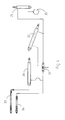
- FIG. 2 shows schematically the control and steering mechanism enabling the swather to operate in the offset position.
- the lower link arms 15 of the tractor are connected to the steering and connecting unit 18, which turns with the tractor around the vertical axis 17.
- the steering rod 19 transmits the steering movement to the link arm unit 20, which turns around the vertical axis 21.
- the second arm in the link arm unit is fastened in an articulated manner to the crossbar 22, the second end of which is likewise fastened in a pivotable manner to the steering arm 23 of the support wheels, which is turnable around the vertical pivot shaft 12 of the support wheel 10 but has a fixed angle relative to the support wheel.
- the wheels 9 and 10 are, in an ordinary manner, connected to each other with a track rod 24.
- the length of the crossbar 22 can be adjusted for offset mode with a telescopic unit, here shown as a hydraulic cylinder 25.
- Figure 3 shows schematically the control mechanism which sets the operating angles ⁇ and ⁇ for the inclined rotors 2 and 3 of the swather.
- One end of the hydraulic cylinder 26 is fixed to the frame 1 and the other end to a sledge 27 displaceable lengthwise on the frame. From this, there extends backwards two link arms 28, 29 to positioning arms 30, 31 of the inclined rotors. These are, as described earlier, fastened to the rear part 4 of the frame turnably around the vertical shafts 5 and 6.
- the length of the link arm 29 can be adjusted with a telescopic unit, here shown as a hydraulic cylinder 32.
- Figure 4 shows a principled sketch of the hydraulics of the machine, where hoses 33, 34 are connected to the external double-acting hydraulic connections (not shown) of the tractor. Further, cylinders 26 and 32 are shown, intended for adjustment of the operating angles ⁇ and ⁇ of the inclined rotors 2 and 3, as well as the cylinder 25 for length adjustment of the crossbar 22. A partially gas-filled hydraulic accumulator 35 is connected to the other outlet of the cylinder 25. Further, a closing valve 36 for the offset adjustment is shown.
- the swather according to the invention operates as follows.
- the lower link arms 15 of the tractor keep the steering and connecting unit 18 perpendicularly to the centre line of the tractor 14.
- the support wheels 9 and 10 are then steered in such a way that they follow the wheel track of the tractor.
- the operating angles ⁇ and ⁇ of the inclined rotors are equally large, and when the valve 36 is closed, the angle adjustment functions in a conventional manner, as described in more detail in FI 20070375 .
- the valve 36 is opened first. Oil is supplied under pressure from the external hydraulic connections of the tractor through the hydraulic hose 33 to the piston rod side on the cylinder 26.
- the cylinder is pulled in, and the inclined rotors 2 and 3 are turned to the operating position through the sledge 27. Since the oil is also simultaneously supplied to the piston side on the cylinder 32, the link arm 28 extends and reduces the folding angle for the inclined rotor 2, and thus ⁇ ⁇ ⁇ , so that both rotors assume also in the offset position principally the same operating angle with regard to the material.
- the oil could be conveyed from the piston rod side of the cylinder 25 back to the tractor via the hose 34.
- the pressure in the hydraulic accumulator 35 opens then the cylinder 25, so that the crossbar 22 extends.
- the support wheels 9 and 10 assume then, through the steering mechanism shown in Figure 3 , a new reference angle with regard to the steering and connecting unit 18, and the rear part 4 of the swather assumes, in driving forwards, an offset position with regard to the centre line 14 of the tractor.
- the new double swath 15 can now be positioned on the ground 16, which was previously between the swaths of the mower conditioner.
- valve 36 is closed.
- the oil on the piston rod side in the cylinders 32 and 25 is now locked up, and the cylinders are in practice riding during the swathing work.
- the cylinder 26, which regulates the working width of the swather can still be driven out and in by means of the hoses 33, 34 connected to the outer hydraulic connections of the tractor. This is a great advantage, particularly in working on a wedge-shaped field.
- Valve 36 being closed, the original steering mechanism steering the rear part 4 of the swather in relation to the driving line of the tractor remains intact also in the offset position, at least to a given extent. In sharp turns to the left (in the implementation according to the description), it may occur that a maximum turning angle is achieved for the support wheels of the machine.
- the crossbar 22 can hereby be compressed such that oil from the cylinder 25 is conveyed back to the hydraulic accumulator 35.
- the steering mechanism functions in the usual way and maintains continuous offset.
- valve 36 When it is desirable to stop offset driving and return to driving in the middle behind the tractor, the valve 36 is opened first. After that, oil is conveyed via the hose 34 to the piston rod side of the cylinders 25 and 32, so that the cylinders are drawn in completely.
- the link arm 28 assumes now its minimum length, which is identical with the length of the link arm 29. This means that the operating angles ⁇ and ⁇ become identical.
- the crossbar 22 assumes its minimum length, and the swather is steered in the middle behind the tractor.
- the greatest advantage of the machine according to the invention is that it enables swathing with an offset swath positioning relative to the centre line of the tractor, which minimizes the contamination of the grass when making wilted grass silage while also improving uniform drying of the material.
- the capacity of the following harvester is increased because the harvester can gather material from larger swaths.
- energy is also saved because the required driving distance on the field with a heavy harvester is twice as short per ton of gathered fodder.
- risk of expensive harvester breakdowns caused by stones in the swath is reduced because the swathing can take place with higher adjustment of the teeth of the inclined rotors which throw the material to the middle.
- the machine may be, for example, provided with work units of a type different from the inclined rotors shown here.
- the adjustment of the offset position does not have to be carried out with hydraulic cylinders but may be carried out by other mechanical or electric adjusting devices.
Abstract
Description
- The present invention relates to a towed swather used in farming for harvesting crop, such as grass, hay or straw, the swather having a large working width and comprising at least two work units mounted individually on a carrier frame provided with wheels, wherein each individual work unit is movably fastened to the centrally positioned carrier frame with at least one vertical articulated shaft and wherein the work units are arranged to gather material to a swath between support wheels of the frame and wherein the work units are further provided with a steering device for improving the capability of the work units to follow the driving line of the tractor either centrally or with an adjustable offset relative to it.
- In phase with increasing requirements for higher capacity in the harvesting of agricultural crop within farming, a large number of different implementations of swathers with a large working width have been provided recently. Many of these are swathers whose work unit is formed of rotors with vertical shafts. An example of such a swather is disclosed in, for example,
EP 1 618 778 (Claas Salgau GmbH) andEP 09373828 FI 20070375 - Wide spreading of the crop after cutting in order to accelerate the wilting process is traditionally the absolutely most common way in Central and Southern Europe. Thus, in these areas, there has been no need to provide a swather where the tractor is not driven on the material. In Scandinavia, by contrast, it is preferred to mow with a mower conditioner, which leaves the cut grass in airy swaths upon the stubble.
- The risk of dirtying is, nevertheless, great even then if it is necessary to drive on the material in the swaths during harvesting. Hereby, it is not only the material tramped down by the tractor wheels that gets contaminated, but also the fact that the pick-up pins in the following harvester must be set much lower to be able to pick up the material not longer lying loosely on the stubble is at least of equally great significance with respect to dirtying. Moist soil and wet grass as well as organic soil types are common in grassland areas particularly in the Nordic countries, and this naturally increases the risk of dirtying.
- The risk of dirtying and the degree of dirtying of the grass has, during the past few years, ironically increased in areas with intensive grassland cultivation and cattle keeping where the farmers, controlled by the environmental regulations of the EU, are often forced to spread fertilizer directly onto the growing grasslands. This is because in practice there is not enough area which is ploughed.
- That is why there is a great risk that the grass silage gets dirty because of residue particles and microbes from the fertilizer that has been spread onto the field only a few weeks before harvesting.
- For example the nitrate directive of the EU has led to spreading right trading between farmers, which is one thing that leads to a multiple health hazard, because the silage is subjected to a risk of contamination, not only from manure and microbes that are already "familiar" to the cattle (that the cattle are already used to) from their own stable but also because of manure and microbes from other sources, such as pig farms and horse stables, that are spread on growing grasslands.
- The several wide-spread epidemics within animal farming in Europe in recent years shows the extremely great importance of good fodder hygiene.
- The usual proceedings in connection with silage harvesting where the grass is cut in swaths with the mower conditioner and the swath is picked up with a precision chopper or a round bale press, generally used in Scandinavia, is highly advantageous with respect to the hygiene aspect. The grass is neither tramped down on the ground nor is it pushed along the ground in connection with separate swathing.
- To improve the drying of these grass swaths, ELHO has developed a rotary tedder with a rigid horizontal rotor (presented in the ELHO Master brochure). With this device, the tractor is driven astride over the swath, so that the material is not tramped down by the tyres. The transverse rotor lifts up and turns the grass in the swath without pushing it along the ground. The fodder remains clean, and it is not a coincidence that Finland, having a very large number of ELHO rotary tedders in use, has the purest milk in Europe.
- ELHO has also developed a corresponding horizontal rotary tedder with a side conveyor at the back to bring the swaths together (see SideFlow model in the above ELHO Master brochure). Here, too, the tractor is driven astride over the swaths, and the fodder remains clean. The disadvantage is, however, that when bringing together two swaths, one of the swaths on the underside remains untouched and wet.
- If, by contrast, a conventional rotor swather of the type disclosed in the above-mentioned patents
EP 1 618 778 ,EP 09373828 FI 20070375 - To alleviate the disadvantages of the above-described and other known solutions, a more advanced model of the swather of
FI 20070375 - The main advantage of the invention is as follows:
- The risk of the fodder getting contaminated because of manure residues and ground microbes is minimized because the tractor can be driven astride over the swath of the mower conditioner, so that its tyres do not tramp down the fodder.
- Drying of the swaths is quicker and more uniform when the swaths are turned upside down on the dried ground between the swaths of the mower conditioner.
- The risk of stones getting to the swath and causing damages for the expensive harvesters is reduced because the rake teeth of the inclined rotor can work with a greater ground clearance, as they do not have to lift up the material having been tramped down by the tractor tyres.
- To achieve this, the invention is characterized by what is defined by the attached claims.
- In the following, the invention is described with reference to the following principled drawings:
-
Figure 1 shows a top view of the swather working in the offset operating position as well as swaths of the mower conditioner and the formed double swath; -
Figure 2 shows schematically the control and steering mechanism enabling the work of the swather in the offset position; -
Figure 3 shows schematically a control mechanism defining the operating angles α and β for the inclined rotors of the swather. - The machine in
Figure 1 is formed of a bearing main frame connected tolower link arms 15 of the tractor and provided with twowork units work units vertical pivot shafts 5 and 6, so that their angle α and β, respectively, can be adjusted with regard to the longitudinal axis of the carrier frame to optimize the operating angle of the inclined rotors with regard to the material in theswaths 7 and 8 of the mower conditioner. - The carrier frame is, at the back, provided with
large support wheels vertical pivot shafts centre line 14 of thetractor 13 to be able to place the newdouble swath 15 on the driedground area 16 between theswaths 7 and 8 of the mower conditioner. - Turnably fastened around the
vertical axis 17 in the front part of the carrier frame 1, there is a steering and connectingunit 18, which is through the connection to thelower link arms 15 of the tractor continuously kept perpendicularly to thecentre line 12 of the tractor. Thelong steering rod 19 connects the steering and connectingunit 18 to thelink arm unit 20 around thevertical axis 21 turnably fastened to the rear part 4 of the carrier frame. -
Figure 2 shows schematically the control and steering mechanism enabling the swather to operate in the offset position. Thelower link arms 15 of the tractor are connected to the steering and connectingunit 18, which turns with the tractor around thevertical axis 17. Thesteering rod 19 transmits the steering movement to thelink arm unit 20, which turns around thevertical axis 21. The second arm in the link arm unit is fastened in an articulated manner to thecrossbar 22, the second end of which is likewise fastened in a pivotable manner to thesteering arm 23 of the support wheels, which is turnable around thevertical pivot shaft 12 of thesupport wheel 10 but has a fixed angle relative to the support wheel. Thewheels track rod 24. - The length of the
crossbar 22 can be adjusted for offset mode with a telescopic unit, here shown as ahydraulic cylinder 25. -
Figure 3 shows schematically the control mechanism which sets the operating angles α and β for theinclined rotors hydraulic cylinder 26 is fixed to the frame 1 and the other end to asledge 27 displaceable lengthwise on the frame. From this, there extends backwards twolink arms arms vertical shafts 5 and 6. The length of thelink arm 29 can be adjusted with a telescopic unit, here shown as ahydraulic cylinder 32. -
Figure 4 shows a principled sketch of the hydraulics of the machine, wherehoses cylinders inclined rotors cylinder 25 for length adjustment of thecrossbar 22. A partially gas-filledhydraulic accumulator 35 is connected to the other outlet of thecylinder 25. Further, a closing valve 36 for the offset adjustment is shown. - The swather according to the invention operates as follows.
- In the operating position where the swath positioning is, as conventionally, directly after the centre line of the tractor, the
lower link arms 15 of the tractor keep the steering and connectingunit 18 perpendicularly to the centre line of thetractor 14. In a conventional way, thesupport wheels - In this form of operation, the operating angles α and β of the inclined rotors are equally large, and when the valve 36 is closed, the angle adjustment functions in a conventional manner, as described in more detail in
FI 20070375 - For adjustment for work with offset swath positioning, the valve 36 is opened first. Oil is supplied under pressure from the external hydraulic connections of the tractor through the
hydraulic hose 33 to the piston rod side on thecylinder 26. The cylinder is pulled in, and theinclined rotors sledge 27. Since the oil is also simultaneously supplied to the piston side on thecylinder 32, thelink arm 28 extends and reduces the folding angle for theinclined rotor 2, and thus α < β, so that both rotors assume also in the offset position principally the same operating angle with regard to the material. At the same time as the valve 36 was opened, the oil could be conveyed from the piston rod side of thecylinder 25 back to the tractor via thehose 34. The pressure in thehydraulic accumulator 35 opens then thecylinder 25, so that thecrossbar 22 extends. Thesupport wheels Figure 3 , a new reference angle with regard to the steering and connectingunit 18, and the rear part 4 of the swather assumes, in driving forwards, an offset position with regard to thecentre line 14 of the tractor. The newdouble swath 15 can now be positioned on theground 16, which was previously between the swaths of the mower conditioner. - After the desired offset position has been achieved, the valve 36 is closed. The oil on the piston rod side in the
cylinders cylinder 26, which regulates the working width of the swather, can still be driven out and in by means of thehoses - Valve 36 being closed, the original steering mechanism steering the rear part 4 of the swather in relation to the driving line of the tractor remains intact also in the offset position, at least to a given extent. In sharp turns to the left (in the implementation according to the description), it may occur that a maximum turning angle is achieved for the support wheels of the machine. To prevent the steering mechanism from being broken down in the driving, the
crossbar 22 can hereby be compressed such that oil from thecylinder 25 is conveyed back to thehydraulic accumulator 35. When the turning angle of the tractor is reduced again, the steering mechanism functions in the usual way and maintains continuous offset. - When it is desirable to stop offset driving and return to driving in the middle behind the tractor, the valve 36 is opened first. After that, oil is conveyed via the
hose 34 to the piston rod side of thecylinders link arm 28 assumes now its minimum length, which is identical with the length of thelink arm 29. This means that the operating angles α and β become identical. Likewise, thecrossbar 22 assumes its minimum length, and the swather is steered in the middle behind the tractor. - The greatest advantage of the machine according to the invention is that it enables swathing with an offset swath positioning relative to the centre line of the tractor, which minimizes the contamination of the grass when making wilted grass silage while also improving uniform drying of the material. This is because the operating principle of the inclined rotors is to throw the material obliquely inwards and, at the same time, to turn both
swaths 7 and 8 mainly upside down, so that their wet underside becomes mainly the upper part of thenew swath 15 without the material is pushed along the ground. Uniform drying is further improved while the new double swath being positioned where the ground has dried up between the originalmower conditioner swaths 7 and 8. - Further, the capacity of the following harvester is increased because the harvester can gather material from larger swaths. Hereby, energy is also saved because the required driving distance on the field with a heavy harvester is twice as short per ton of gathered fodder. Also the risk of expensive harvester breakdowns caused by stones in the swath is reduced because the swathing can take place with higher adjustment of the teeth of the inclined rotors which throw the material to the middle.
- The invention is naturally not confined to the above preferred embodiments but a large number of variations are feasible within the scope of the attached claims. Thus, the machine may be, for example, provided with work units of a type different from the inclined rotors shown here. Further, the adjustment of the offset position does not have to be carried out with hydraulic cylinders but may be carried out by other mechanical or electric adjusting devices.
Claims (10)
- A swather used in farming for harvesting crop, such as grass, hay or straw, the swather having a large working width and comprising at least two work units (2, 3) mounted individually on a carrier frame provided with wheels, wherein each individual work unit is movably fastened to the centrally positioned carrier frame (1) with at least one vertical articulated shaft and wherein the work units are arranged to gather material to a swath (15) between support wheels (9, 10) of the frame, characterized in that the support wheels can be turned in such a position that the swath (15) is placed with a sideways displacement relative to the centre line (14) of the tractor.
- A swather according to claim 1, characterized in that the support wheels (9, 10) are provided with a steering device for improving the capability of the swather to follow the driving line (14) of the tractor either centrally or with an adjustable sideways displacement relative to the driving line.
- A swather according to claims 1 to 2, characterized in that the work units (2, 3) are formed of inclined rotors rotating around horizontal axes.
- A swather according to claim 3, characterized in that the angle (α and β) of the work units relative to the carrier frame (1) can be adjusted during driving.
- A swather according to claim 4, characterized in that the angles (α and β) of the work units relative to the carrier frame (1) can be defined in the sideways displaced operating position to be different for the left and the right work unit (2, 3), so that the angle of the work units relative to the driving direction and the material to be gathered is hereby optimized.
- A swather according to claim 5, characterized in that the angle (α) of at least one of the work units relative to the carrier frame (1) in the adjustment to the sideways displaced operating position is automatically compensated relative to the extent of the sideways displacement.
- A swather according to claim 2, characterized in that the steering device of the support wheels (9, 10) is in the sideways displaced operating position provided with a device enabling the tractor to turn more sharply than the maximum steering angle for the support wheels (9, 10) would allow.
- A swather according to claim 7, characterized in that this device is formed of a flexible telescopic element (25) connected to a bar (22) of the steering device.
- A swather according to claim 7, characterized in that this device is formed of a hydraulic cylinder (25) connected to the bar (22) of the steering device and having a hydraulic accumulator (35) connected thereto.
- A swather according to claim 2 and 4, characterized in that the same hydraulic hoses (33, 34) connected to the tractor are used for adjusting the working width of the machine and for setting the swather in the sideways displaced operating position.
Priority Applications (1)
| Application Number | Priority Date | Filing Date | Title |
|---|---|---|---|
| PL08167728T PL2030499T3 (en) | 2007-08-28 | 2008-10-28 | Towed swather |
Applications Claiming Priority (1)
| Application Number | Priority Date | Filing Date | Title |
|---|---|---|---|
| FI20070649A FI120815B (en) | 2007-08-28 | 2007-08-28 | Trailed rake |
Publications (3)
| Publication Number | Publication Date |
|---|---|
| EP2030499A2 true EP2030499A2 (en) | 2009-03-04 |
| EP2030499A3 EP2030499A3 (en) | 2009-09-23 |
| EP2030499B1 EP2030499B1 (en) | 2011-12-07 |
Family
ID=38468715
Family Applications (1)
| Application Number | Title | Priority Date | Filing Date |
|---|---|---|---|
| EP08167728A Active EP2030499B1 (en) | 2007-08-28 | 2008-10-28 | Towed swather |
Country Status (4)
| Country | Link |
|---|---|
| EP (1) | EP2030499B1 (en) |
| AT (1) | ATE536093T1 (en) |
| FI (1) | FI120815B (en) |
| PL (1) | PL2030499T3 (en) |
Cited By (3)
| Publication number | Priority date | Publication date | Assignee | Title |
|---|---|---|---|---|
| EP2327289A1 (en) * | 2009-11-06 | 2011-06-01 | Oy El-Ho Ab | Mounted swather |
| CN102530574A (en) * | 2011-12-12 | 2012-07-04 | 淮安市捷达粮食设备有限公司 | Quick stacker for collecting cereals in sunning ground |
| GB2534121A (en) * | 2014-12-10 | 2016-07-20 | Dowson Walton John | Swath conditioning machine |
Citations (4)
| Publication number | Priority date | Publication date | Assignee | Title |
|---|---|---|---|---|
| US4723401A (en) | 1986-09-24 | 1988-02-09 | New Holland Inc. | Steerable wheel assembly for unitized rakes |
| EP0937382A1 (en) | 1998-02-20 | 1999-08-25 | NIEMEYER Landmaschinen GmbH | Rotary tedder |
| EP1618778A1 (en) | 2004-07-20 | 2006-01-25 | Claas Saulgau Gmbh | Rotary swather |
| EP1668977A2 (en) | 2004-12-13 | 2006-06-14 | Lely Enterprises AG | A hay-making machine |
Family Cites Families (3)
| Publication number | Priority date | Publication date | Assignee | Title |
|---|---|---|---|---|
| DE4206504C2 (en) * | 1992-03-02 | 1996-06-05 | Krone Bernhard Gmbh Maschf | Haymaking machine |
| FR2819374B1 (en) * | 2001-01-17 | 2007-04-06 | Bevan Ashford | ARTICULATED ANDAINEUS |
| NL1031873C1 (en) * | 2006-05-02 | 2007-11-05 | Maasland Nv | Haymaking machine. |
-
2007
- 2007-08-28 FI FI20070649A patent/FI120815B/en active IP Right Grant
-
2008
- 2008-10-28 AT AT08167728T patent/ATE536093T1/en active
- 2008-10-28 EP EP08167728A patent/EP2030499B1/en active Active
- 2008-10-28 PL PL08167728T patent/PL2030499T3/en unknown
Patent Citations (4)
| Publication number | Priority date | Publication date | Assignee | Title |
|---|---|---|---|---|
| US4723401A (en) | 1986-09-24 | 1988-02-09 | New Holland Inc. | Steerable wheel assembly for unitized rakes |
| EP0937382A1 (en) | 1998-02-20 | 1999-08-25 | NIEMEYER Landmaschinen GmbH | Rotary tedder |
| EP1618778A1 (en) | 2004-07-20 | 2006-01-25 | Claas Saulgau Gmbh | Rotary swather |
| EP1668977A2 (en) | 2004-12-13 | 2006-06-14 | Lely Enterprises AG | A hay-making machine |
Cited By (3)
| Publication number | Priority date | Publication date | Assignee | Title |
|---|---|---|---|---|
| EP2327289A1 (en) * | 2009-11-06 | 2011-06-01 | Oy El-Ho Ab | Mounted swather |
| CN102530574A (en) * | 2011-12-12 | 2012-07-04 | 淮安市捷达粮食设备有限公司 | Quick stacker for collecting cereals in sunning ground |
| GB2534121A (en) * | 2014-12-10 | 2016-07-20 | Dowson Walton John | Swath conditioning machine |
Also Published As
| Publication number | Publication date |
|---|---|
| FI20070649A (en) | 2009-03-01 |
| EP2030499B1 (en) | 2011-12-07 |
| EP2030499A3 (en) | 2009-09-23 |
| FI120815B (en) | 2010-03-31 |
| FI20070649A0 (en) | 2007-08-28 |
| ATE536093T1 (en) | 2011-12-15 |
| PL2030499T3 (en) | 2012-05-31 |
Similar Documents
| Publication | Publication Date | Title |
|---|---|---|
| US7818954B2 (en) | Corn stalk baling method and apparatus | |
| EP1364569B1 (en) | Mower | |
| US20080314015A1 (en) | Raking Device Disposed Between Outer Raking Devices | |
| AU717426B2 (en) | A hay-making machine | |
| US10264730B2 (en) | Agricultural tool control system | |
| EP0865235B1 (en) | A machine combination, a rake and pick-up and displacing member, as well as a method | |
| WO1994004020A2 (en) | Automotive baling press for plants cultivated in the field | |
| EP2030499B1 (en) | Towed swather | |
| EP0715804B1 (en) | A machine for processing crop lying on the soil | |
| US20020059790A1 (en) | Combined baler and rake apparatus | |
| EP3454636B1 (en) | Crop handling apparatus | |
| US3362144A (en) | Harvester | |
| JP4426775B2 (en) | Roll baler | |
| US20150059308A1 (en) | Combined device for windrowing and for pressing into bales, particularly for hay | |
| RU2137342C1 (en) | Plant fractional harvesting combine | |
| EP1138190B1 (en) | A bale press and a method of processing crop | |
| US20240099194A1 (en) | Mower-conditioner having fins on control surfaces | |
| RU21326U1 (en) | UNIT FOR SEPARATE HARVESTING OF HERBS ON A SHEET AND STEM FRACTION | |
| Buchs | Simple Practices for Better Hay | |
| Sahay et al. | Tractor drawn fodder harvester for large forage production farms | |
| Swart | Argo-at the forefront of haymaking technology | |
| EP0887010A1 (en) | A method of, as well as an implement for adjusting an agricultural machine, such as a hay-making machine | |
| Cavalchini | CIGR Handbook of Agricultural Engineering, Volume III Plant Production Engineering, Chapter 1 Machines for Crop Production, 1.6. Harvesters and Threshers, Part 1.6. 8-1.6. 10 Harvesters and Threshers: Forage Crops | |
| RO129507A2 (en) | Technical equipment for harvesting and mincing green fodder | |
| NZ272238A (en) | Rotary hay rake and tedder; dual purpose machine coupled to a tractor, details regarding conversion of the machine from raking to tedding mode and vice versa |
Legal Events
| Date | Code | Title | Description |
|---|---|---|---|
| PUAI | Public reference made under article 153(3) epc to a published international application that has entered the european phase |
Free format text: ORIGINAL CODE: 0009012 |
|
| AK | Designated contracting states |
Kind code of ref document: A2 Designated state(s): AT BE BG CH CY CZ DE DK EE ES FI FR GB GR HR HU IE IS IT LI LT LU LV MC MT NL NO PL PT RO SE SI SK TR |
|
| AX | Request for extension of the european patent |
Extension state: AL BA MK RS |
|
| PUAL | Search report despatched |
Free format text: ORIGINAL CODE: 0009013 |
|
| AK | Designated contracting states |
Kind code of ref document: A3 Designated state(s): AT BE BG CH CY CZ DE DK EE ES FI FR GB GR HR HU IE IS IT LI LT LU LV MC MT NL NO PL PT RO SE SI SK TR |
|
| AX | Request for extension of the european patent |
Extension state: AL BA MK RS |
|
| 17P | Request for examination filed |
Effective date: 20100208 |
|
| 17Q | First examination report despatched |
Effective date: 20100301 |
|
| AKX | Designation fees paid |
Designated state(s): AT BE BG CH CY CZ DE DK EE ES FI FR GB GR HR HU IE IS IT LI LT LU LV MC MT NL NO PL PT RO SE SI SK TR |
|
| 17Q | First examination report despatched |
Effective date: 20100709 |
|
| GRAP | Despatch of communication of intention to grant a patent |
Free format text: ORIGINAL CODE: EPIDOSNIGR1 |
|
| GRAS | Grant fee paid |
Free format text: ORIGINAL CODE: EPIDOSNIGR3 |
|
| GRAA | (expected) grant |
Free format text: ORIGINAL CODE: 0009210 |
|
| AK | Designated contracting states |
Kind code of ref document: B1 Designated state(s): AT BE BG CH CY CZ DE DK EE ES FI FR GB GR HR HU IE IS IT LI LT LU LV MC MT NL NO PL PT RO SE SI SK TR |
|
| REG | Reference to a national code |
Ref country code: GB Ref legal event code: FG4D |
|
| REG | Reference to a national code |
Ref country code: CH Ref legal event code: EP |
|
| REG | Reference to a national code |
Ref country code: IE Ref legal event code: FG4D |
|
| REG | Reference to a national code |
Ref country code: DE Ref legal event code: R096 Ref document number: 602008011821 Country of ref document: DE Effective date: 20120223 |
|
| REG | Reference to a national code |
Ref country code: NL Ref legal event code: VDEP Effective date: 20111207 |
|
| PG25 | Lapsed in a contracting state [announced via postgrant information from national office to epo] |
Ref country code: NO Free format text: LAPSE BECAUSE OF FAILURE TO SUBMIT A TRANSLATION OF THE DESCRIPTION OR TO PAY THE FEE WITHIN THE PRESCRIBED TIME-LIMIT Effective date: 20120307 Ref country code: LT Free format text: LAPSE BECAUSE OF FAILURE TO SUBMIT A TRANSLATION OF THE DESCRIPTION OR TO PAY THE FEE WITHIN THE PRESCRIBED TIME-LIMIT Effective date: 20111207 |
|
| LTIE | Lt: invalidation of european patent or patent extension |
Effective date: 20111207 |
|
| PG25 | Lapsed in a contracting state [announced via postgrant information from national office to epo] |
Ref country code: HR Free format text: LAPSE BECAUSE OF FAILURE TO SUBMIT A TRANSLATION OF THE DESCRIPTION OR TO PAY THE FEE WITHIN THE PRESCRIBED TIME-LIMIT Effective date: 20111207 Ref country code: GR Free format text: LAPSE BECAUSE OF FAILURE TO SUBMIT A TRANSLATION OF THE DESCRIPTION OR TO PAY THE FEE WITHIN THE PRESCRIBED TIME-LIMIT Effective date: 20120308 Ref country code: SE Free format text: LAPSE BECAUSE OF FAILURE TO SUBMIT A TRANSLATION OF THE DESCRIPTION OR TO PAY THE FEE WITHIN THE PRESCRIBED TIME-LIMIT Effective date: 20111207 Ref country code: LV Free format text: LAPSE BECAUSE OF FAILURE TO SUBMIT A TRANSLATION OF THE DESCRIPTION OR TO PAY THE FEE WITHIN THE PRESCRIBED TIME-LIMIT Effective date: 20111207 Ref country code: SI Free format text: LAPSE BECAUSE OF FAILURE TO SUBMIT A TRANSLATION OF THE DESCRIPTION OR TO PAY THE FEE WITHIN THE PRESCRIBED TIME-LIMIT Effective date: 20111207 Ref country code: NL Free format text: LAPSE BECAUSE OF FAILURE TO SUBMIT A TRANSLATION OF THE DESCRIPTION OR TO PAY THE FEE WITHIN THE PRESCRIBED TIME-LIMIT Effective date: 20111207 |
|
| REG | Reference to a national code |
Ref country code: PL Ref legal event code: T3 |
|
| PG25 | Lapsed in a contracting state [announced via postgrant information from national office to epo] |
Ref country code: CY Free format text: LAPSE BECAUSE OF FAILURE TO SUBMIT A TRANSLATION OF THE DESCRIPTION OR TO PAY THE FEE WITHIN THE PRESCRIBED TIME-LIMIT Effective date: 20111207 Ref country code: BE Free format text: LAPSE BECAUSE OF FAILURE TO SUBMIT A TRANSLATION OF THE DESCRIPTION OR TO PAY THE FEE WITHIN THE PRESCRIBED TIME-LIMIT Effective date: 20111207 |
|
| PG25 | Lapsed in a contracting state [announced via postgrant information from national office to epo] |
Ref country code: BG Free format text: LAPSE BECAUSE OF FAILURE TO SUBMIT A TRANSLATION OF THE DESCRIPTION OR TO PAY THE FEE WITHIN THE PRESCRIBED TIME-LIMIT Effective date: 20120307 Ref country code: CZ Free format text: LAPSE BECAUSE OF FAILURE TO SUBMIT A TRANSLATION OF THE DESCRIPTION OR TO PAY THE FEE WITHIN THE PRESCRIBED TIME-LIMIT Effective date: 20111207 Ref country code: IS Free format text: LAPSE BECAUSE OF FAILURE TO SUBMIT A TRANSLATION OF THE DESCRIPTION OR TO PAY THE FEE WITHIN THE PRESCRIBED TIME-LIMIT Effective date: 20120407 Ref country code: SK Free format text: LAPSE BECAUSE OF FAILURE TO SUBMIT A TRANSLATION OF THE DESCRIPTION OR TO PAY THE FEE WITHIN THE PRESCRIBED TIME-LIMIT Effective date: 20111207 Ref country code: EE Free format text: LAPSE BECAUSE OF FAILURE TO SUBMIT A TRANSLATION OF THE DESCRIPTION OR TO PAY THE FEE WITHIN THE PRESCRIBED TIME-LIMIT Effective date: 20111207 |
|
| REG | Reference to a national code |
Ref country code: DE Ref legal event code: R081 Ref document number: 602008011821 Country of ref document: DE Owner name: OY EL-HO AB, FI Free format text: FORMER OWNER: OY EL-HO AB, BENNAES, FI Effective date: 20120626 |
|
| PG25 | Lapsed in a contracting state [announced via postgrant information from national office to epo] |
Ref country code: RO Free format text: LAPSE BECAUSE OF FAILURE TO SUBMIT A TRANSLATION OF THE DESCRIPTION OR TO PAY THE FEE WITHIN THE PRESCRIBED TIME-LIMIT Effective date: 20111207 Ref country code: PT Free format text: LAPSE BECAUSE OF FAILURE TO SUBMIT A TRANSLATION OF THE DESCRIPTION OR TO PAY THE FEE WITHIN THE PRESCRIBED TIME-LIMIT Effective date: 20120409 |
|
| REG | Reference to a national code |
Ref country code: AT Ref legal event code: MK05 Ref document number: 536093 Country of ref document: AT Kind code of ref document: T Effective date: 20111207 |
|
| PLBE | No opposition filed within time limit |
Free format text: ORIGINAL CODE: 0009261 |
|
| STAA | Information on the status of an ep patent application or granted ep patent |
Free format text: STATUS: NO OPPOSITION FILED WITHIN TIME LIMIT |
|
| PG25 | Lapsed in a contracting state [announced via postgrant information from national office to epo] |
Ref country code: DK Free format text: LAPSE BECAUSE OF FAILURE TO SUBMIT A TRANSLATION OF THE DESCRIPTION OR TO PAY THE FEE WITHIN THE PRESCRIBED TIME-LIMIT Effective date: 20111207 |
|
| 26N | No opposition filed |
Effective date: 20120910 |
|
| PG25 | Lapsed in a contracting state [announced via postgrant information from national office to epo] |
Ref country code: IT Free format text: LAPSE BECAUSE OF FAILURE TO SUBMIT A TRANSLATION OF THE DESCRIPTION OR TO PAY THE FEE WITHIN THE PRESCRIBED TIME-LIMIT Effective date: 20111207 |
|
| REG | Reference to a national code |
Ref country code: DE Ref legal event code: R097 Ref document number: 602008011821 Country of ref document: DE Effective date: 20120910 |
|
| PG25 | Lapsed in a contracting state [announced via postgrant information from national office to epo] |
Ref country code: AT Free format text: LAPSE BECAUSE OF FAILURE TO SUBMIT A TRANSLATION OF THE DESCRIPTION OR TO PAY THE FEE WITHIN THE PRESCRIBED TIME-LIMIT Effective date: 20111207 |
|
| PGFP | Annual fee paid to national office [announced via postgrant information from national office to epo] |
Ref country code: GB Payment date: 20121024 Year of fee payment: 5 |
|
| PG25 | Lapsed in a contracting state [announced via postgrant information from national office to epo] |
Ref country code: ES Free format text: LAPSE BECAUSE OF FAILURE TO SUBMIT A TRANSLATION OF THE DESCRIPTION OR TO PAY THE FEE WITHIN THE PRESCRIBED TIME-LIMIT Effective date: 20120318 |
|
| PG25 | Lapsed in a contracting state [announced via postgrant information from national office to epo] |
Ref country code: MC Free format text: LAPSE BECAUSE OF NON-PAYMENT OF DUE FEES Effective date: 20121031 |
|
| REG | Reference to a national code |
Ref country code: CH Ref legal event code: PL |
|
| PG25 | Lapsed in a contracting state [announced via postgrant information from national office to epo] |
Ref country code: FI Free format text: LAPSE BECAUSE OF FAILURE TO SUBMIT A TRANSLATION OF THE DESCRIPTION OR TO PAY THE FEE WITHIN THE PRESCRIBED TIME-LIMIT Effective date: 20111207 |
|
| PG25 | Lapsed in a contracting state [announced via postgrant information from national office to epo] |
Ref country code: CH Free format text: LAPSE BECAUSE OF NON-PAYMENT OF DUE FEES Effective date: 20121031 Ref country code: LI Free format text: LAPSE BECAUSE OF NON-PAYMENT OF DUE FEES Effective date: 20121031 |
|
| REG | Reference to a national code |
Ref country code: IE Ref legal event code: MM4A |
|
| PG25 | Lapsed in a contracting state [announced via postgrant information from national office to epo] |
Ref country code: IE Free format text: LAPSE BECAUSE OF NON-PAYMENT OF DUE FEES Effective date: 20121028 |
|
| PG25 | Lapsed in a contracting state [announced via postgrant information from national office to epo] |
Ref country code: MT Free format text: LAPSE BECAUSE OF FAILURE TO SUBMIT A TRANSLATION OF THE DESCRIPTION OR TO PAY THE FEE WITHIN THE PRESCRIBED TIME-LIMIT Effective date: 20111207 |
|
| PG25 | Lapsed in a contracting state [announced via postgrant information from national office to epo] |
Ref country code: TR Free format text: LAPSE BECAUSE OF FAILURE TO SUBMIT A TRANSLATION OF THE DESCRIPTION OR TO PAY THE FEE WITHIN THE PRESCRIBED TIME-LIMIT Effective date: 20111207 |
|
| PG25 | Lapsed in a contracting state [announced via postgrant information from national office to epo] |
Ref country code: LU Free format text: LAPSE BECAUSE OF NON-PAYMENT OF DUE FEES Effective date: 20121028 |
|
| GBPC | Gb: european patent ceased through non-payment of renewal fee |
Effective date: 20131028 |
|
| PG25 | Lapsed in a contracting state [announced via postgrant information from national office to epo] |
Ref country code: GB Free format text: LAPSE BECAUSE OF NON-PAYMENT OF DUE FEES Effective date: 20131028 Ref country code: HU Free format text: LAPSE BECAUSE OF FAILURE TO SUBMIT A TRANSLATION OF THE DESCRIPTION OR TO PAY THE FEE WITHIN THE PRESCRIBED TIME-LIMIT Effective date: 20081028 |
|
| REG | Reference to a national code |
Ref country code: FR Ref legal event code: PLFP Year of fee payment: 8 |
|
| REG | Reference to a national code |
Ref country code: FR Ref legal event code: PLFP Year of fee payment: 9 |
|
| REG | Reference to a national code |
Ref country code: FR Ref legal event code: PLFP Year of fee payment: 10 |
|
| REG | Reference to a national code |
Ref country code: FR Ref legal event code: PLFP Year of fee payment: 11 |
|
| PGFP | Annual fee paid to national office [announced via postgrant information from national office to epo] |
Ref country code: PL Payment date: 20221003 Year of fee payment: 15 |
|
| PGFP | Annual fee paid to national office [announced via postgrant information from national office to epo] |
Ref country code: FR Payment date: 20231016 Year of fee payment: 16 Ref country code: DE Payment date: 20231020 Year of fee payment: 16 |
|
| PGFP | Annual fee paid to national office [announced via postgrant information from national office to epo] |
Ref country code: PL Payment date: 20231009 Year of fee payment: 16 |