EP2029374B1 - A pressure relief device for an inflatable tire - Google Patents
A pressure relief device for an inflatable tire Download PDFInfo
- Publication number
- EP2029374B1 EP2029374B1 EP20070722624 EP07722624A EP2029374B1 EP 2029374 B1 EP2029374 B1 EP 2029374B1 EP 20070722624 EP20070722624 EP 20070722624 EP 07722624 A EP07722624 A EP 07722624A EP 2029374 B1 EP2029374 B1 EP 2029374B1
- Authority
- EP
- European Patent Office
- Prior art keywords
- pin
- pressure
- tire
- passage
- section
- Prior art date
- Legal status (The legal status is an assumption and is not a legal conclusion. Google has not performed a legal analysis and makes no representation as to the accuracy of the status listed.)
- Not-in-force
Links
- 238000007789 sealing Methods 0.000 claims description 17
- 230000006835 compression Effects 0.000 claims description 10
- 238000007906 compression Methods 0.000 claims description 10
- 230000037431 insertion Effects 0.000 description 4
- 238000003780 insertion Methods 0.000 description 4
- 239000000463 material Substances 0.000 description 2
- 230000007547 defect Effects 0.000 description 1
- 238000006073 displacement reaction Methods 0.000 description 1
- 239000000428 dust Substances 0.000 description 1
- 230000003993 interaction Effects 0.000 description 1
- 210000003141 lower extremity Anatomy 0.000 description 1
- 238000004519 manufacturing process Methods 0.000 description 1
- 230000003287 optical effect Effects 0.000 description 1
- 210000001364 upper extremity Anatomy 0.000 description 1
Images
Classifications
-
- B—PERFORMING OPERATIONS; TRANSPORTING
- B60—VEHICLES IN GENERAL
- B60C—VEHICLE TYRES; TYRE INFLATION; TYRE CHANGING; CONNECTING VALVES TO INFLATABLE ELASTIC BODIES IN GENERAL; DEVICES OR ARRANGEMENTS RELATED TO TYRES
- B60C29/00—Arrangements of tyre-inflating valves to tyres or rims; Accessories for tyre-inflating valves, not otherwise provided for
- B60C29/06—Accessories for tyre-inflating valves, e.g. housings, guards, covers for valve caps, locks, not otherwise provided for
-
- B—PERFORMING OPERATIONS; TRANSPORTING
- B60—VEHICLES IN GENERAL
- B60C—VEHICLE TYRES; TYRE INFLATION; TYRE CHANGING; CONNECTING VALVES TO INFLATABLE ELASTIC BODIES IN GENERAL; DEVICES OR ARRANGEMENTS RELATED TO TYRES
- B60C29/00—Arrangements of tyre-inflating valves to tyres or rims; Accessories for tyre-inflating valves, not otherwise provided for
- B60C29/06—Accessories for tyre-inflating valves, e.g. housings, guards, covers for valve caps, locks, not otherwise provided for
- B60C29/068—Pressure relief devices, i.e. safety devices for overpressure
-
- Y—GENERAL TAGGING OF NEW TECHNOLOGICAL DEVELOPMENTS; GENERAL TAGGING OF CROSS-SECTIONAL TECHNOLOGIES SPANNING OVER SEVERAL SECTIONS OF THE IPC; TECHNICAL SUBJECTS COVERED BY FORMER USPC CROSS-REFERENCE ART COLLECTIONS [XRACs] AND DIGESTS
- Y10—TECHNICAL SUBJECTS COVERED BY FORMER USPC
- Y10T—TECHNICAL SUBJECTS COVERED BY FORMER US CLASSIFICATION
- Y10T137/00—Fluid handling
- Y10T137/3584—Inflatable article [e.g., tire filling chuck and/or stem]
-
- Y—GENERAL TAGGING OF NEW TECHNOLOGICAL DEVELOPMENTS; GENERAL TAGGING OF CROSS-SECTIONAL TECHNOLOGIES SPANNING OVER SEVERAL SECTIONS OF THE IPC; TECHNICAL SUBJECTS COVERED BY FORMER USPC CROSS-REFERENCE ART COLLECTIONS [XRACs] AND DIGESTS
- Y10—TECHNICAL SUBJECTS COVERED BY FORMER USPC
- Y10T—TECHNICAL SUBJECTS COVERED BY FORMER US CLASSIFICATION
- Y10T137/00—Fluid handling
- Y10T137/3584—Inflatable article [e.g., tire filling chuck and/or stem]
- Y10T137/36—With pressure-responsive pressure-control means
- Y10T137/3646—Co-axial inflation and relief valves
-
- Y—GENERAL TAGGING OF NEW TECHNOLOGICAL DEVELOPMENTS; GENERAL TAGGING OF CROSS-SECTIONAL TECHNOLOGIES SPANNING OVER SEVERAL SECTIONS OF THE IPC; TECHNICAL SUBJECTS COVERED BY FORMER USPC CROSS-REFERENCE ART COLLECTIONS [XRACs] AND DIGESTS
- Y10—TECHNICAL SUBJECTS COVERED BY FORMER USPC
- Y10T—TECHNICAL SUBJECTS COVERED BY FORMER US CLASSIFICATION
- Y10T137/00—Fluid handling
- Y10T137/3584—Inflatable article [e.g., tire filling chuck and/or stem]
- Y10T137/3662—With gauge or indicator
- Y10T137/3677—With deflating means
-
- Y—GENERAL TAGGING OF NEW TECHNOLOGICAL DEVELOPMENTS; GENERAL TAGGING OF CROSS-SECTIONAL TECHNOLOGIES SPANNING OVER SEVERAL SECTIONS OF THE IPC; TECHNICAL SUBJECTS COVERED BY FORMER USPC CROSS-REFERENCE ART COLLECTIONS [XRACs] AND DIGESTS
- Y10—TECHNICAL SUBJECTS COVERED BY FORMER USPC
- Y10T—TECHNICAL SUBJECTS COVERED BY FORMER US CLASSIFICATION
- Y10T137/00—Fluid handling
- Y10T137/3584—Inflatable article [e.g., tire filling chuck and/or stem]
- Y10T137/3709—Stem attached relief valve
Definitions
- the present invention relates to a pressure relief device for an inflatable tire, in particular a vehicular tire.
- the device is intended to release air from the tire when the pressure in the tire exceeds a certain threshold value or to prevent excess air from being forced into the tire during inflation thereof.
- US patent No. 3,830,249 discloses a device in which a pressure relief ball is maintained in a seated position by a force applied by a compression spring until the air pressure within the tire exceeds a set pressure. When the set pressure has been exceeded, the pressure relief ball is unseated from the body, and surplus air escapes from the tire via the pressure relief device.
- US patent No. 4,660,590 corresponding with the preamble of claim 1, is concerned with an inflation pressure regulator with a substantially friction-free flexing seal arrangement within a housing of the regulator which bypasses the tire when the pressure within the tire reaches a predetermined level.
- a sealing section of a flexure member is normally urged into sealing contact with a seat surface owing to the force exerted against the flexure member by a spring/ring combination.
- the pressure in a first chamber in the housing will exert sufficient force against the upper face of the flexure member to cause a flexing in a portion thereof and a consequential movement of the sealing section away from the seat surface, allowing air to escape via an exhaust aperture.
- a further device is known from US patent No. 6,125,694 , which discloses an audibly reporting pressure-relief, automatic tire assembly for use in interaction with preexisiting valve core stems on a tire.
- WO 2005/042277 discloses a pressure relief device comprising a ring-shaped resilient member which is contractively fitted around an outer surface portion of a body of the device, whereby the resilient is stretched to relieve air when the air pressure inside the body exceeds a predetermined level.
- the present invention provides pressure relief device for an inflatable tire, comprising:
- the device may be mass-produced at low cost, as, for example, separate air conduits are not required.
- the pressure-relief mechanism may comprise a spring element arranged in the body, the spring element exerting a closing force on a closure element, so that the closure element opens at the predetermined pressure level.
- the closure element may include a first part, on which the spring acts, and a second part, which closes and seals a passage to the chamber.
- the first part is preferably made from a material, which is relatively rigid compared to the material of the second part.
- the second part is preferably elastomeric, e.g. made from rubber.
- the pressure relief mechanism may further comprise a passage connecting the chamber to an exterior environment, the passage being normally closed by the spring-biased closure element, the closure element being arranged such that the pressure in the chamber exerts a force on the closure member.
- the closure element is preferably longitudinally displaceable in the body, such that it may be lifted off its seat when the pressure in the chamber exceeds the predetermined pressure level.
- the pressure-relief mechanism comprises a compression spring, which extends coaxially with the pin.
- the pin may conveniently have a smaller diameter than the internal diameter of the spring, so that the pin may extend through the spring.
- the distortion of the compression spring is may be adjustable to adjust said predetermined pressure level. The possibility of adjustment of the distortion may e.g. be achieved by arranging the spring between two elements, the mutual distance of which may be varied.
- the pin is preferably guided in the passageway in the body.
- the pin may have a thickened section, which is accommodated in a section of increased diameter in the passageway.
- a resilient sealing member may form a seal between the pin and the passageway, the resilient sealing member being arranged such that it is forced into sealing engagement with the pin and the passage under the action of air pressure in the body.
- a bottom portion of the body may define a cavity for receiving a valve of the tire within the body, e.g. centrally within the body, and a top portion of the body may be adapted to be connected to an inflation device, such as a pump or compressor.
- an inflation device such as a pump or compressor.
- the passage in the pin may comprise a transversely extending inlet section and/or a transversely extending outlet section, which are interconnected by a longitudinally extending main section.
- the transversely inlet section preferably communicates with an inlet cavity in a top section of the body, and the transversely extending outlet section preferably communicates with the chamber.
- the pin is open-ended near its inlet end and protected by a first insert member, in which an inlet port is formed as a transversely or longitudinally extending passage.
- the transversely extending outlet section may be arranged at a distance from that end portion of the pin, which is intended to engage the stem of the tire during inflation thereof, so that engagement of the relatively weak area surrounding the outlet opening with other parts is prevented.
- the pin may be open-ended near its outlet end, there being optionally provided a second insert member extending into the open outlet end of the pin, the second insert member having an outer diameter, which is smaller than the inner diameter of the passage in the pin, so that an annular flow channel is formed between the second insert member and the inner wall of the pin.
- the first and second inserts protect the pin against dirt and dust.
- the device comprises a failsafe means for ensuring that air may escape out of the device in order to prevent pressure from building up in the device with the risk of exploding the device or the tire which is being inflated.
- a failsafe means may e.g. comprise a weakened section in the body, the properties of which are such that it breaks at a pressure which is higher than at least one of said first and second predetermined pressure level.
- a section of the body's outer wall may have a reduced thickness, so that the wall breaks at a certain pressure.
- a bottom portion of the body preferably defines a cavity for receiving a valve of the tire within the body, the cavity most preferably defining a threaded portion for screwing the device onto a threaded portion of a tire valve.
- a top portion of the body may be adapted to connect the inflation valve in the body to an inflation device, such as an air inflation nozzle.
- the air conduit is preferably arranged radially displaced with respect to the cavity near the bottom portion.
- acoustic signal In order to notify a user when the predetermined threshold pressure level has been reached or exceeded during inflation of the tire, there may be provided means for emitting an acoustic signal or means for emitting an optical signal when the air pressure in the chamber has reached or exceeds the predetermined pressure level.
- the acoustic signal is generated as a whistling tone generated by excess air flowing past out of the device. Once the excess air has escaped, the flow of excess air stops, and the whistling tone will stop.
- electronic means e.g. in the form of an electronic pressure sensor coupled to a light-emitting means or an electronically controlled sound source.
- the invention further provides a kit comprising a plurality of pressure relief devices, wherein the devices define different predetermined pressure levels.
- each device in the kit is easily identifiable by a user, so that each individual device in the kit may be associated with a particular pressure level.
- the predetermined threshold pressure level of each device of the kit may be indicated on a visible surface of the device.
- a combination of a pressure relief device as disclosed herein and an inflatable tire may be permanently integrated with the tire, for example with a stem of the tire, e.g. to form one integrated unit, or it may be releasably attached to the stem of the tire.
- the invention also provides a rim for an inflatable tire, the rim comprising a pressure relief device according to the invention, the pressure relief device being optionally integrated a valve for inflation of the tire. Further, the invention provides a wheel comprising such a rim and an inflatable tire.
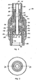
- the pressure relief device 100 a body 102, and a pin 104 for releasing a stem of a tire valve (not shown).
- the pin 104 is slidingly mounted in a passageway 106 in the body.
- a bottom portion of the body defines a chamber 116 for receiving a valve of a tire (not shown) centrally within the body.
- An insertion element 118 is fitted into the bottom portion of the body.
- the insertion element defines a threaded portion 120 for attaching the pressure relief device to the tire valve.
- the pin 104 defines a longitudinally extending air conduit passage 108, rounded end portions 113 and 115, as well as transversely extending inlet 110 and transversely extending outlet 112.
- the pin 104 is longitudinally slidable in the passageway 106, increased-diameter section 107 of which accommodates a thickened section 109 of the pin 104.
- the upper and lower extremities of the increased-diameter section 107 define the maximum stroke of the pin 104.
- the body 102 comprises an upper portion 122 with an inlet area 124 in the form of a cavity for receiving an inflation device, such as a pump or compressor.
- the body further comprises an inner intermediate section 126, which is screwed into the upper portion 122 by means of threads 128.
- the intermediate section 126 defines the increased-diameter section 107.
- the body comprises an outer section 130 as well as insertion element 118 as described above.
- a pressure relief mechanism including a compression spring 134, one end of which rests against the intermediate section 126, and another end of which acts on a closure element 136.
- the closure element holds a ring-shaped elastomeric closure member 138, which, in the closed configuration shown in Fig. 1 , keeps flow passages 140 closed.
- four elastomeric closure members 138 are provided.
- a cavity or chamber 142 is defined between the outer section 130 and the closure element 136, the cavity 142 communicating with the exterior environment via passages 144.
- a sealing member 146 provides a seal between the pin and the passageway in the body to prevent unintentional air leakage along an outer surface of the pin.
- the sealing member 146 is arranged such that air pressure in the chamber 116 forces it into sealing engagement with the pin.
- the upper portion of the body may form a sealing portion 147, e.g. at the bottom of section of inlet area 124, the sealing portion 147 being preferably arranged such that the inlet pressure in the inlet area 124 forces it into sealing engagement with the pin.
- a separate sealing member (not shown) may be provided.
- the pressure relief device is operated as follows: the device is screwed onto an outer surface portion of a tire valve by means of the threaded portion 120 of the insertion element 118, the tire valve being thereby received in the chamber 116.
- An inflation device such as an air hose nozzle, which is connected to a pressurized source, is then attached to the upper portion 122 of the body 102, with a stem of the inflation device (not shown) contacting the upper surface 113 of the pin 104.
- the pin 104 is thereby pressed downwards until the lower end surface 115 of the pin 104 contacts the upper end of the valve stem (not shown) associated with the tire to thereby open the tire valve. Air flows from the pressurized source to the interior of the tire via the passage 108 in the pin 104.
- the air pressure in the chamber 116 and the flow passages 140 is thus essentially equal to the tire pressure.
- the pressure in the air conduit and the flow passages 140 exerts a force on the closure members 138.
- the force acting upwardly on the closure members 138 is sufficient to overcome the downwardly acting force of the compression spring 134.
- air may escape to the exterior environment via flow passages 140, cavity 142 and passages 144.
- the threshold pressure level is determined by the properties of the compression spring 134, the surface area of the closure members 138, and the distortion of the compression spring 134.
- the distortion of the compression spring may be varied by displacement (rotation) of the upper portion 122.
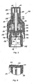
- Figs. 3 and 4 illustrate a second embodiment of a pressure relief device according to the present invention
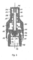
- Fig. 5 illustrates a third embodiment.
- Figs. 1 and 2 illustrate a second embodiment of a pressure relief device according to the present invention
- Fig. 5 illustrates a third embodiment.
- Figs. 1 and 2 illustrate a second embodiment of a pressure relief device according to the present invention
- Fig. 5 illustrates a third embodiment.
- the pin 204 is provided in the form of an open-ended tubular pipe.
- a first insert member 206 is provided in the inlet area 124 for closing the open end of the pin 204. As shown in the detail of Fig. 4 , the first insert member 206 closes circumferentially towards an inner wall of the upper body portion 122 at 212.
- a transversely extending inlet port 210 is provided in the first insert member 206.
- a second insert member 214 is provided, the second insert member 214 having a smaller outer diameter than the inner diameter of the pin 204, so that an annular flow outlet passage 212 is provided.
- the intermediate section 126 present in the embodiment of Figs. 1-4 has been omitted.
- a ring element 226 is optionally provided, the height of the ring element 226 determining the distortion of the spring 234 and hence the relief threshold pressure of the device.
- the outer section 130 of the body 102 and the upper body portion 122 may be formed as one single element.
Landscapes
- Engineering & Computer Science (AREA)
- Mechanical Engineering (AREA)
- Safety Valves (AREA)
Description
- The present invention relates to a pressure relief device for an inflatable tire, in particular a vehicular tire. The device is intended to release air from the tire when the pressure in the tire exceeds a certain threshold value or to prevent excess air from being forced into the tire during inflation thereof.
- Various pressure relief devices for inflatable tires have been proposed in the prior art.
US patent No. 3,830,249 discloses a device in which a pressure relief ball is maintained in a seated position by a force applied by a compression spring until the air pressure within the tire exceeds a set pressure. When the set pressure has been exceeded, the pressure relief ball is unseated from the body, and surplus air escapes from the tire via the pressure relief device. -
US patent No. 4,660,590 , corresponding with the preamble of claim 1, is concerned with an inflation pressure regulator with a substantially friction-free flexing seal arrangement within a housing of the regulator which bypasses the tire when the pressure within the tire reaches a predetermined level. A sealing section of a flexure member is normally urged into sealing contact with a seat surface owing to the force exerted against the flexure member by a spring/ring combination. When the tire has been inflated to the pressure rating of the regulator, the pressure in a first chamber in the housing will exert sufficient force against the upper face of the flexure member to cause a flexing in a portion thereof and a consequential movement of the sealing section away from the seat surface, allowing air to escape via an exhaust aperture. - A further device is known from
US patent No. 6,125,694 , which discloses an audibly reporting pressure-relief, automatic tire assembly for use in interaction with preexisiting valve core stems on a tire. -
WO 2005/042277 discloses a pressure relief device comprising a ring-shaped resilient member which is contractively fitted around an outer surface portion of a body of the device, whereby the resilient is stretched to relieve air when the air pressure inside the body exceeds a predetermined level. - It is an object of preferred embodiments of the present invention to provide a reliable pressure relief device. It is a further object of preferred embodiments of the invention to provide a compact device which causes reduced inertial imbalance of a tire to which the device is mounted, as compared to known devices. It is a further object of preferred embodiments of the invention to provide a pressure relief device which is resistant to wear and tear. It is a still further object of preferred embodiments of the invention to provide a device which allows for a variable threshold pressure level, or various embodiments of which may be manufactured with variable threshold pressures while maintaining low production costs.
- The present invention provides pressure relief device for an inflatable tire, comprising:
- a body having a chamber therein;
- an air inlet connectable to an inflation device;
- an air outlet connectable to a valve of a tire;
- a conduit for leading air from the inflation device to the tire during inflation thereof;
- a pin arranged to slide axially in a passageway in the body, the pin extending from the air inlet to the air outlet and being slidable between a first position in which it cannot release a stem of the tire, and a second position, in which it can release the stem;
- a pressure relief mechanism for releasing air from the chamber when the pressure therein exceeds a predetermined level;
- As the passage is provided in the pin, the device may be mass-produced at low cost, as, for example, separate air conduits are not required.
- The pressure-relief mechanism may comprise a spring element arranged in the body, the spring element exerting a closing force on a closure element, so that the closure element opens at the predetermined pressure level. The closure element may include a first part, on which the spring acts, and a second part, which closes and seals a passage to the chamber. The first part is preferably made from a material, which is relatively rigid compared to the material of the second part. The second part is preferably elastomeric, e.g. made from rubber.
- The pressure relief mechanism may further comprise a passage connecting the chamber to an exterior environment, the passage being normally closed by the spring-biased closure element, the closure element being arranged such that the pressure in the chamber exerts a force on the closure member. The closure element is preferably longitudinally displaceable in the body, such that it may be lifted off its seat when the pressure in the chamber exceeds the predetermined pressure level.
- In one embodiment, the pressure-relief mechanism comprises a compression spring, which extends coaxially with the pin. The pin may conveniently have a smaller diameter than the internal diameter of the spring, so that the pin may extend through the spring. The distortion of the compression spring is may be adjustable to adjust said predetermined pressure level. The possibility of adjustment of the distortion may e.g. be achieved by arranging the spring between two elements, the mutual distance of which may be varied.
- The pin is preferably guided in the passageway in the body. In order to axially retain the pin in the body, the pin may have a thickened section, which is accommodated in a section of increased diameter in the passageway.
- A resilient sealing member may form a seal between the pin and the passageway, the resilient sealing member being arranged such that it is forced into sealing engagement with the pin and the passage under the action of air pressure in the body. Thus, there is provided a reliable seal, which prevents air from escaping from the chamber to the inlet area of the device.
- A bottom portion of the body may define a cavity for receiving a valve of the tire within the body, e.g. centrally within the body, and a top portion of the body may be adapted to be connected to an inflation device, such as a pump or compressor.
- In order to protect the conduit through the pin from mechanical damage and dirt, the passage in the pin may comprise a transversely extending inlet section and/or a transversely extending outlet section, which are interconnected by a longitudinally extending main section. The transversely inlet section preferably communicates with an inlet cavity in a top section of the body, and the transversely extending outlet section preferably communicates with the chamber. In one embodiment, the pin is open-ended near its inlet end and protected by a first insert member, in which an inlet port is formed as a transversely or longitudinally extending passage. The transversely extending outlet section may be arranged at a distance from that end portion of the pin, which is intended to engage the stem of the tire during inflation thereof, so that engagement of the relatively weak area surrounding the outlet opening with other parts is prevented. Alternatively, the pin may be open-ended near its outlet end, there being optionally provided a second insert member extending into the open outlet end of the pin, the second insert member having an outer diameter, which is smaller than the inner diameter of the passage in the pin, so that an annular flow channel is formed between the second insert member and the inner wall of the pin. The first and second inserts protect the pin against dirt and dust.
- In case the overpressure valve is defect, it may be desirable that the device comprises a failsafe means for ensuring that air may escape out of the device in order to prevent pressure from building up in the device with the risk of exploding the device or the tire which is being inflated. One such failsafe means may e.g. comprise a weakened section in the body, the properties of which are such that it breaks at a pressure which is higher than at least one of said first and second predetermined pressure level. For example, a section of the body's outer wall may have a reduced thickness, so that the wall breaks at a certain pressure.
- A bottom portion of the body preferably defines a cavity for receiving a valve of the tire within the body, the cavity most preferably defining a threaded portion for screwing the device onto a threaded portion of a tire valve. A top portion of the body may be adapted to connect the inflation valve in the body to an inflation device, such as an air inflation nozzle. In order to ensure a short longitudinal extent of the device, the air conduit is preferably arranged radially displaced with respect to the cavity near the bottom portion.
- In order to notify a user when the predetermined threshold pressure level has been reached or exceeded during inflation of the tire, there may be provided means for emitting an acoustic signal or means for emitting an optical signal when the air pressure in the chamber has reached or exceeds the predetermined pressure level. In one embodiment, the acoustic signal is generated as a whistling tone generated by excess air flowing past out of the device. Once the excess air has escaped, the flow of excess air stops, and the whistling tone will stop. Alternatively, there may be provided electronic means, e.g. in the form of an electronic pressure sensor coupled to a light-emitting means or an electronically controlled sound source.
- The invention further provides a kit comprising a plurality of pressure relief devices, wherein the devices define different predetermined pressure levels. Preferably, each device in the kit is easily identifiable by a user, so that each individual device in the kit may be associated with a particular pressure level. For example, the predetermined threshold pressure level of each device of the kit may be indicated on a visible surface of the device.
- In a further aspect there is provided a combination of a pressure relief device as disclosed herein and an inflatable tire. The pressure relief device may be permanently integrated with the tire, for example with a stem of the tire, e.g. to form one integrated unit, or it may be releasably attached to the stem of the tire. The invention also provides a rim for an inflatable tire, the rim comprising a pressure relief device according to the invention, the pressure relief device being optionally integrated a valve for inflation of the tire. Further, the invention provides a wheel comprising such a rim and an inflatable tire.
- Embodiment of a pressure relief device according to the invention will now be described with reference to the accompanying drawings, in which:
-
Figs. 1 and 2 illustrate a first embodiment; -
Figs. 3 and 4 illustrate a second embodiment; -
Fig. 5 illustrates a third embodiment. - The pressure relief device 100 a
body 102, and apin 104 for releasing a stem of a tire valve (not shown). Thepin 104 is slidingly mounted in apassageway 106 in the body. A bottom portion of the body defines achamber 116 for receiving a valve of a tire (not shown) centrally within the body. Aninsertion element 118 is fitted into the bottom portion of the body. The insertion element defines a threadedportion 120 for attaching the pressure relief device to the tire valve. Thepin 104 defines a longitudinally extendingair conduit passage 108,rounded end portions 113 and 115, as well as transversely extending inlet 110 and transversely extendingoutlet 112. Thepin 104 is longitudinally slidable in thepassageway 106, increased-diameter section 107 of which accommodates a thickenedsection 109 of thepin 104. The upper and lower extremities of the increased-diameter section 107 define the maximum stroke of thepin 104. - The
body 102 comprises anupper portion 122 with aninlet area 124 in the form of a cavity for receiving an inflation device, such as a pump or compressor. The body further comprises an innerintermediate section 126, which is screwed into theupper portion 122 by means ofthreads 128. Theintermediate section 126 defines the increased-diameter section 107. Further, the body comprises anouter section 130 as well asinsertion element 118 as described above. - Within the body there is provided a pressure relief mechanism including a
compression spring 134, one end of which rests against theintermediate section 126, and another end of which acts on aclosure element 136. The closure element holds a ring-shapedelastomeric closure member 138, which, in the closed configuration shown inFig. 1 , keepsflow passages 140 closed. Alternatively, fourelastomeric closure members 138 are provided. A cavity orchamber 142 is defined between theouter section 130 and theclosure element 136, thecavity 142 communicating with the exterior environment viapassages 144. A sealingmember 146 provides a seal between the pin and the passageway in the body to prevent unintentional air leakage along an outer surface of the pin. The sealingmember 146 is arranged such that air pressure in thechamber 116 forces it into sealing engagement with the pin. The upper portion of the body may form a sealing portion 147, e.g. at the bottom of section ofinlet area 124, the sealing portion 147 being preferably arranged such that the inlet pressure in theinlet area 124 forces it into sealing engagement with the pin. As an alternative to the sealing portion, a separate sealing member (not shown) may be provided. - The pressure relief device is operated as follows: the device is screwed onto an outer surface portion of a tire valve by means of the threaded
portion 120 of theinsertion element 118, the tire valve being thereby received in thechamber 116. An inflation device, such as an air hose nozzle, which is connected to a pressurized source, is then attached to theupper portion 122 of thebody 102, with a stem of the inflation device (not shown) contacting theupper surface 113 of thepin 104. Thepin 104 is thereby pressed downwards until the lower end surface 115 of thepin 104 contacts the upper end of the valve stem (not shown) associated with the tire to thereby open the tire valve. Air flows from the pressurized source to the interior of the tire via thepassage 108 in thepin 104. The air pressure in thechamber 116 and theflow passages 140 is thus essentially equal to the tire pressure. The pressure in the air conduit and theflow passages 140 exerts a force on theclosure members 138. When the pressure in theflow passages 140 and thus in the tire reaches a certain threshold level, the force acting upwardly on theclosure members 138 is sufficient to overcome the downwardly acting force of thecompression spring 134. Thus, air may escape to the exterior environment viaflow passages 140,cavity 142 andpassages 144. - The threshold pressure level is determined by the properties of the
compression spring 134, the surface area of theclosure members 138, and the distortion of thecompression spring 134. The distortion of the compression spring may be varied by displacement (rotation) of theupper portion 122. -
Figs. 3 and 4 illustrate a second embodiment of a pressure relief device according to the present invention, andFig. 5 illustrates a third embodiment. Below, only the differences between the embodiments ofFigs. 1 and 2 on the one hand, andFigs. 3-5 on the other will be discussed. To the extent that identical elements or elements performing identical functions are present in the embodiments ofFigs. 3-5 , such elements are identified by the same reference numerals as inFigs. 1 and 2 . It will hence be understood that the description of such elements included above in relation toFigs. 1 and 2 also applies to the below description ofFigs. 3-5 . The device ofFigs. 3-5 operates in a similar manner as the device ofFigs. 1 and 2 . - In the embodiment of
Figs. 3-5 , thepin 204 is provided in the form of an open-ended tubular pipe. Afirst insert member 206 is provided in theinlet area 124 for closing the open end of thepin 204. As shown in the detail ofFig. 4 , thefirst insert member 206 closes circumferentially towards an inner wall of theupper body portion 122 at 212. A transversely extendinginlet port 210 is provided in thefirst insert member 206. At the opposite, outlet end of thepin 204, asecond insert member 214 is provided, thesecond insert member 214 having a smaller outer diameter than the inner diameter of thepin 204, so that an annularflow outlet passage 212 is provided. - In the embodiment of
Fig. 5 , theintermediate section 126 present in the embodiment ofFigs. 1-4 has been omitted. Aring element 226 is optionally provided, the height of thering element 226 determining the distortion of the spring 234 and hence the relief threshold pressure of the device. - The
outer section 130 of thebody 102 and theupper body portion 122 may be formed as one single element.
Claims (12)
- A pressure relief device for an inflatable tire, comprising:- a body (102) having a chamber (142) therein;- an air inlet (110;210) connectable to an inflation device;- an air outlet (112;212) connectable to a valve of a tire;- a conduit (108;208) for leading air from the inflation device to the tire during inflation thereof;- a pin (104;204) arranged to slide axially in a passageway (106) in the body (102), the pin (104;204) extending from the air inlet (110;210) to the air outlet (112;212) and being slidable between a first position in which it cannot release a stem of the tire, and a second position, in which it can release the stem;- a pressure relief mechanism for releasing air from the chamber (142) when the pressure therein exceeds a predetermined level;
characterised in that said conduit (108;208) is provided as a passage in the pin (104;204). - A device according to claim 1, wherein the pressure-relief mechanism comprises a spring element (134;234) arranged in the body (102), the spring element (134;234) exerting a closing force on a closure element (136;236), so that the closure element (136;236) opens at said predetermined pressure level.
- A device according to claim 2, wherein the pressure relief mechanism comprises a passage (144) connecting the chamber (142) to an exterior environment, the passage (144) being normally closed by the closure element (136;236), the closure element (136;236) being arranged such that the pressure in the chamber (142) exerts a force on the closure element (136;236) to open the passage (144) when the force derived from the pressure in the chamber (142) exceeds a counteracting closing force of the pressure-relief mechanism.
- A device according to claim 3, wherien the pressure-relief mechanism comprises a compression spring (134;234), which extends coaxially with the pin (104;204).
- A device according to claim 4, wherein the distortion of the compression spring (134;234) is adjustable to adjust said predetermined pressure level.
- A device according to any of the preceding claims, wherein the pin (104;204) is guided in the passageway (106) in the body (102), the pin (104;204) having a thickened section (109), which is accommodated in a section (107) of increased diameter in the passageway (106), whereby the thickened section (109) and the increased diameter section (107) provide an axial retainment of the pin (104;204) in the body (102).
- A device according to any of claims 1-5, wherein the pin (104;204) is guided in the passageway (106) in the body (102), and wherein at least one resilient sealing member (138) forms a seal between the pin (104;204) and the passageway(106), the resilient sealing member (138) being arranged such that it is forced into sealing engagement with the pin (104;204) and the passage (144) under the action of air pressure in the body (102).
- A device according to any of the preceding claims, wherein the passage (144) in the pin (104;204) comprises at least one of: a transversely extending inlet section (110;210) and a transversely extending outlet section (112;212).
- A device according to claim 8, wherein the transversely extending outlet section (112;212) communicates with said chamber (142).
- A device according to claim 8 or 9, wherein the transversely extending outlet section (112;212) is arranged at a distance from that end portion of the pin (104;204), which is intended to engage the stem of the tire during inflation thereof.
- A device according to any of the preceding claims, wherein the passage (108;208) in the pin (104;204) is open-ended.
- An inflatable tire comprising a pressure relief device according to any of the preceding claims.
Priority Applications (1)
| Application Number | Priority Date | Filing Date | Title |
|---|---|---|---|
| EP20070722624 EP2029374B1 (en) | 2006-05-24 | 2007-05-24 | A pressure relief device for an inflatable tire |
Applications Claiming Priority (4)
| Application Number | Priority Date | Filing Date | Title |
|---|---|---|---|
| US80277006P | 2006-05-24 | 2006-05-24 | |
| EP06010893 | 2006-05-24 | ||
| EP20070722624 EP2029374B1 (en) | 2006-05-24 | 2007-05-24 | A pressure relief device for an inflatable tire |
| PCT/DK2007/000246 WO2007134611A1 (en) | 2006-05-24 | 2007-05-24 | A pressure relief device for an inflatable tire |
Publications (2)
| Publication Number | Publication Date |
|---|---|
| EP2029374A1 EP2029374A1 (en) | 2009-03-04 |
| EP2029374B1 true EP2029374B1 (en) | 2013-01-16 |
Family
ID=38229067
Family Applications (1)
| Application Number | Title | Priority Date | Filing Date |
|---|---|---|---|
| EP20070722624 Not-in-force EP2029374B1 (en) | 2006-05-24 | 2007-05-24 | A pressure relief device for an inflatable tire |
Country Status (4)
| Country | Link |
|---|---|
| US (1) | US8256447B2 (en) |
| EP (1) | EP2029374B1 (en) |
| JP (1) | JP5097199B2 (en) |
| WO (1) | WO2007134611A1 (en) |
Families Citing this family (21)
| Publication number | Priority date | Publication date | Assignee | Title |
|---|---|---|---|---|
| EP2369208A1 (en) | 2010-03-18 | 2011-09-28 | Smart Parts Nordic A/S | A valve device for an inflatable tire |
| HK1172204A2 (en) * | 2011-08-12 | 2013-04-05 | 冠翔(香港)工业有限公司 | Auto decompression valve |
| MX354548B (en) | 2012-07-13 | 2018-03-09 | Dana Heavy Vehicle Sys Group | Valve assemblies and methods of inflating or deflating a tyre. |
| FR3013655A1 (en) * | 2013-11-28 | 2015-05-29 | Schrader | INFLATION INFLATING AND EXHAUST DEVICE FOR A PNEUMATIC WHEEL |
| US10259272B2 (en) | 2014-01-03 | 2019-04-16 | Dana Heavy Vehicle Systems Group, Llc | Assembly for a central tire inflation system |
| FR3020991B1 (en) * | 2014-05-13 | 2016-05-13 | Stephane Fazekas | AUTOMATIC INFLATION-DEFLATION DEVICE FOR CONTAINING CAPACITY OF A GASEOUS FLUID UNDER PRESSURE |
| WO2015197603A1 (en) | 2014-06-23 | 2015-12-30 | Quickfill Products Aps | A filling device for an inflatable unit |
| JP6399564B2 (en) | 2014-06-30 | 2018-10-03 | ダナ ヘビー ビーイクル システィムズ グループ、エルエルシー | Valve assembly for tire pressure management system |
| FR3023896B1 (en) | 2014-07-17 | 2016-07-15 | Schrader | SAFETY VALVE |
| KR101618284B1 (en) * | 2015-03-11 | 2016-05-04 | 조영호 | Back pressure maintenance by-pass valve |
| US10843511B2 (en) | 2015-08-06 | 2020-11-24 | Dana Heavy Vehicle Systems Group, Llc | Channel valve assembly for a tire pressure management system |
| DE112016003576T5 (en) | 2015-08-06 | 2018-05-03 | Dana Heavy Vehicle Systems Group, Llc | CONTROL AND FEED VALVE ASSEMBLY FOR A TIRE PRESSURE MANAGEMENT SYSTEM |
| US10214059B2 (en) | 2015-10-16 | 2019-02-26 | Dana Heavy Vehicle Systems Group, Llc | Tire pressure management system and method of decreasing tire pressure |
| BR112018015329A2 (en) * | 2016-01-29 | 2018-12-18 | Dana Heavy Vehicle Sys Group | tire inflation system set |
| CN106015667B (en) | 2016-05-12 | 2018-04-17 | 明达实业(厦门)有限公司 | Tuyere relief valve |
| TWI642917B (en) * | 2017-09-15 | 2018-12-01 | 吳樹木 | Quick inflation joint with pressure gauge |
| TWI642918B (en) * | 2017-09-21 | 2018-12-01 | 吳樹木 | Inflatable joint that is easy to interpret air pressure values |
| FR3074095B1 (en) * | 2017-11-30 | 2020-12-11 | Ateq | APPARATUS FOR TESTING A CALIBRATED LEAK OF GAS ON A PNEUMATIC VALVE, PLUG FOR SUCH AN APPARATUS, AND ASSOCIATED PROCEDURE FOR CHECKING FOR LEAK DETECTION. |
| US10563783B2 (en) | 2018-07-12 | 2020-02-18 | Innoflate, LLC | Pressure regulating device |
| KR102306697B1 (en) * | 2019-12-10 | 2021-09-30 | 정우정공주식회사 | Safety valve to prevent foreign substances from entering the vacuum tank |
| CN113685588A (en) * | 2021-07-30 | 2021-11-23 | 宁波铭匠扎啤设备有限公司 | a safety valve |
Family Cites Families (18)
| Publication number | Priority date | Publication date | Assignee | Title |
|---|---|---|---|---|
| US1114796A (en) * | 1914-01-23 | 1914-10-27 | Thomas B Nickel | Safety-valve. |
| US1481018A (en) * | 1923-01-10 | 1924-01-15 | Littman Zeno | Pneumatic-tire valve |
| US1735918A (en) * | 1928-04-16 | 1929-11-19 | John J Dobil | Mop and brush holder |
| US3315695A (en) * | 1964-09-03 | 1967-04-25 | Eaton Mfg Co | Valve extension |
| US3830249A (en) | 1972-08-07 | 1974-08-20 | R Fleenor | Tire inflator device |
| JPS50124375U (en) * | 1974-03-27 | 1975-10-11 | ||
| JPS607924Y2 (en) * | 1977-05-26 | 1985-03-19 | 旭産業株式会社 | air supply equipment |
| US4445527A (en) * | 1982-07-16 | 1984-05-01 | Eaton Corporation | Valve extension |
| US4660590A (en) * | 1986-08-08 | 1987-04-28 | Kenneth E. Berger | Inflation pressure regulator |
| CN1143958C (en) * | 1995-02-03 | 2004-03-31 | Nvb国际公司 | Valve connector |
| US5778923A (en) * | 1995-10-25 | 1998-07-14 | Marston; Philip William | Anti-seepage self-gauging inflation valve system |
| CN1208568C (en) * | 1999-09-02 | 2005-06-29 | 盛夏阳 | Regulators and their usage |
| US7032611B1 (en) * | 1999-09-02 | 2006-04-25 | Xiayang Sheng | Pressure regulator and method of use |
| US6125694A (en) | 1999-09-22 | 2000-10-03 | Bledsoe; Douglas K. | Circumferentially disposed automatic whistling tire pressure gauge warning and limiting assembly |
| US6105600A (en) * | 1999-10-01 | 2000-08-22 | Wang; Lopin | Inflation device comprising a connection head compatible with inflation valves of U.S. type and french type |
| ATE274160T1 (en) * | 2000-12-28 | 2004-09-15 | Col Ven Sa | THREE WAY PRESSURE REGULATOR VALVE |
| NZ538725A (en) * | 2002-09-13 | 2008-05-30 | Halkey Roberts Corp | Combination inflation and relief valve |
| CN100509453C (en) | 2003-11-04 | 2009-07-08 | 发明人工厂有限责任公司 | A pressure relief device for an inflatable tire |
-
2007
- 2007-05-24 US US12/227,410 patent/US8256447B2/en not_active Expired - Fee Related
- 2007-05-24 EP EP20070722624 patent/EP2029374B1/en not_active Not-in-force
- 2007-05-24 JP JP2009511336A patent/JP5097199B2/en not_active Expired - Fee Related
- 2007-05-24 WO PCT/DK2007/000246 patent/WO2007134611A1/en not_active Ceased
Also Published As
| Publication number | Publication date |
|---|---|
| US8256447B2 (en) | 2012-09-04 |
| WO2007134611A1 (en) | 2007-11-29 |
| EP2029374A1 (en) | 2009-03-04 |
| US20090308462A1 (en) | 2009-12-17 |
| JP5097199B2 (en) | 2012-12-12 |
| JP2009537387A (en) | 2009-10-29 |
Similar Documents
| Publication | Publication Date | Title |
|---|---|---|
| US8256447B2 (en) | Pressure relief device for an inflatable tire | |
| US7404412B2 (en) | Inflation stem with blow-off valve to prevent overinflation | |
| US20100207445A1 (en) | Central Tire Inflation Wheel Assembly and Valve | |
| US5957151A (en) | Automatic pressure regulating valve | |
| CA2927341C (en) | Pneumatic pressure relief test plug | |
| EP1689599B1 (en) | A pressure relief device for an inflatable tire | |
| US10228067B2 (en) | Valve assembly for inflatable bodies | |
| EP3442813B1 (en) | Valve assembly for a tire pressure management system | |
| EP3097333B1 (en) | Pressure controlled and pressure control valve for an inflatable object | |
| US4015624A (en) | Tire valve | |
| US7073527B1 (en) | Assignable pressure governor valve | |
| EP1545912B1 (en) | Air flow control apparatus | |
| US7401619B2 (en) | Air valve device for an inflatable article | |
| CN101479120B (en) | A pressure relief device for an inflatable tire | |
| JP2007510104A5 (en) | ||
| WO2016094633A1 (en) | Valve assembly for a tire pressure management system | |
| EP2369208A1 (en) | A valve device for an inflatable tire | |
| US20040123901A1 (en) | Fluid control apparatus | |
| US20040020534A1 (en) | Controlled pneumatic valve | |
| US4235255A (en) | Tire inflation guide | |
| US6901944B2 (en) | Fluid control apparatus | |
| US10864786B2 (en) | Highflow air coupling device and system | |
| RU2266207C1 (en) | Pneumatic tire pressure checking device (versions) | |
| AU739467B2 (en) | A pressure cutoff valve | |
| JPH0659817B2 (en) | Hydraulic control valve |
Legal Events
| Date | Code | Title | Description |
|---|---|---|---|
| PUAI | Public reference made under article 153(3) epc to a published international application that has entered the european phase |
Free format text: ORIGINAL CODE: 0009012 |
|
| 17P | Request for examination filed |
Effective date: 20081229 |
|
| AK | Designated contracting states |
Kind code of ref document: A1 Designated state(s): AT BE BG CH CY CZ DE DK EE ES FI FR GB GR HU IE IS IT LI LT LU LV MC MT NL PL PT RO SE SI SK TR |
|
| AX | Request for extension of the european patent |
Extension state: AL BA HR MK RS |
|
| 17Q | First examination report despatched |
Effective date: 20090427 |
|
| GRAP | Despatch of communication of intention to grant a patent |
Free format text: ORIGINAL CODE: EPIDOSNIGR1 |
|
| DAX | Request for extension of the european patent (deleted) | ||
| RAP1 | Party data changed (applicant data changed or rights of an application transferred) |
Owner name: OPFINDERFABRIKKEN APS |
|
| GRAS | Grant fee paid |
Free format text: ORIGINAL CODE: EPIDOSNIGR3 |
|
| GRAA | (expected) grant |
Free format text: ORIGINAL CODE: 0009210 |
|
| AK | Designated contracting states |
Kind code of ref document: B1 Designated state(s): AT BE BG CH CY CZ DE DK EE ES FI FR GB GR HU IE IS IT LI LT LU LV MC MT NL PL PT RO SE SI SK TR |
|
| REG | Reference to a national code |
Ref country code: GB Ref legal event code: FG4D |
|
| REG | Reference to a national code |
Ref country code: CH Ref legal event code: EP |
|
| REG | Reference to a national code |
Ref country code: IE Ref legal event code: FG4D |
|
| REG | Reference to a national code |
Ref country code: AT Ref legal event code: REF Ref document number: 593680 Country of ref document: AT Kind code of ref document: T Effective date: 20130215 Ref country code: CH Ref legal event code: EP |
|
| REG | Reference to a national code |
Ref country code: DE Ref legal event code: R096 Ref document number: 602007028071 Country of ref document: DE Effective date: 20130314 |
|
| REG | Reference to a national code |
Ref country code: AT Ref legal event code: MK05 Ref document number: 593680 Country of ref document: AT Kind code of ref document: T Effective date: 20130116 |
|
| REG | Reference to a national code |
Ref country code: NL Ref legal event code: VDEP Effective date: 20130116 |
|
| REG | Reference to a national code |
Ref country code: LT Ref legal event code: MG4D |
|
| RAP2 | Party data changed (patent owner data changed or rights of a patent transferred) |
Owner name: QUICKFILL PRODUCTS APS |
|
| PG25 | Lapsed in a contracting state [announced via postgrant information from national office to epo] |
Ref country code: LT Free format text: LAPSE BECAUSE OF FAILURE TO SUBMIT A TRANSLATION OF THE DESCRIPTION OR TO PAY THE FEE WITHIN THE PRESCRIBED TIME-LIMIT Effective date: 20130116 Ref country code: SE Free format text: LAPSE BECAUSE OF FAILURE TO SUBMIT A TRANSLATION OF THE DESCRIPTION OR TO PAY THE FEE WITHIN THE PRESCRIBED TIME-LIMIT Effective date: 20130116 Ref country code: BE Free format text: LAPSE BECAUSE OF FAILURE TO SUBMIT A TRANSLATION OF THE DESCRIPTION OR TO PAY THE FEE WITHIN THE PRESCRIBED TIME-LIMIT Effective date: 20130116 Ref country code: AT Free format text: LAPSE BECAUSE OF FAILURE TO SUBMIT A TRANSLATION OF THE DESCRIPTION OR TO PAY THE FEE WITHIN THE PRESCRIBED TIME-LIMIT Effective date: 20130116 Ref country code: ES Free format text: LAPSE BECAUSE OF FAILURE TO SUBMIT A TRANSLATION OF THE DESCRIPTION OR TO PAY THE FEE WITHIN THE PRESCRIBED TIME-LIMIT Effective date: 20130427 Ref country code: IS Free format text: LAPSE BECAUSE OF FAILURE TO SUBMIT A TRANSLATION OF THE DESCRIPTION OR TO PAY THE FEE WITHIN THE PRESCRIBED TIME-LIMIT Effective date: 20130516 Ref country code: BG Free format text: LAPSE BECAUSE OF FAILURE TO SUBMIT A TRANSLATION OF THE DESCRIPTION OR TO PAY THE FEE WITHIN THE PRESCRIBED TIME-LIMIT Effective date: 20130416 |
|
| PG25 | Lapsed in a contracting state [announced via postgrant information from national office to epo] |
Ref country code: PT Free format text: LAPSE BECAUSE OF FAILURE TO SUBMIT A TRANSLATION OF THE DESCRIPTION OR TO PAY THE FEE WITHIN THE PRESCRIBED TIME-LIMIT Effective date: 20130516 Ref country code: PL Free format text: LAPSE BECAUSE OF FAILURE TO SUBMIT A TRANSLATION OF THE DESCRIPTION OR TO PAY THE FEE WITHIN THE PRESCRIBED TIME-LIMIT Effective date: 20130116 Ref country code: LV Free format text: LAPSE BECAUSE OF FAILURE TO SUBMIT A TRANSLATION OF THE DESCRIPTION OR TO PAY THE FEE WITHIN THE PRESCRIBED TIME-LIMIT Effective date: 20130116 Ref country code: GR Free format text: LAPSE BECAUSE OF FAILURE TO SUBMIT A TRANSLATION OF THE DESCRIPTION OR TO PAY THE FEE WITHIN THE PRESCRIBED TIME-LIMIT Effective date: 20130417 Ref country code: NL Free format text: LAPSE BECAUSE OF FAILURE TO SUBMIT A TRANSLATION OF THE DESCRIPTION OR TO PAY THE FEE WITHIN THE PRESCRIBED TIME-LIMIT Effective date: 20130116 Ref country code: FI Free format text: LAPSE BECAUSE OF FAILURE TO SUBMIT A TRANSLATION OF THE DESCRIPTION OR TO PAY THE FEE WITHIN THE PRESCRIBED TIME-LIMIT Effective date: 20130116 Ref country code: SI Free format text: LAPSE BECAUSE OF FAILURE TO SUBMIT A TRANSLATION OF THE DESCRIPTION OR TO PAY THE FEE WITHIN THE PRESCRIBED TIME-LIMIT Effective date: 20130116 |
|
| REG | Reference to a national code |
Ref country code: DE Ref legal event code: R081 Ref document number: 602007028071 Country of ref document: DE Owner name: QUICKFILL PRODUCTS APS, DK Free format text: FORMER OWNER: OPFINDERFABRIKKEN APS, KLAMPENBORG, DK Effective date: 20130828 |
|
| PG25 | Lapsed in a contracting state [announced via postgrant information from national office to epo] |
Ref country code: DK Free format text: LAPSE BECAUSE OF FAILURE TO SUBMIT A TRANSLATION OF THE DESCRIPTION OR TO PAY THE FEE WITHIN THE PRESCRIBED TIME-LIMIT Effective date: 20130116 Ref country code: CZ Free format text: LAPSE BECAUSE OF FAILURE TO SUBMIT A TRANSLATION OF THE DESCRIPTION OR TO PAY THE FEE WITHIN THE PRESCRIBED TIME-LIMIT Effective date: 20130116 Ref country code: SK Free format text: LAPSE BECAUSE OF FAILURE TO SUBMIT A TRANSLATION OF THE DESCRIPTION OR TO PAY THE FEE WITHIN THE PRESCRIBED TIME-LIMIT Effective date: 20130116 Ref country code: EE Free format text: LAPSE BECAUSE OF FAILURE TO SUBMIT A TRANSLATION OF THE DESCRIPTION OR TO PAY THE FEE WITHIN THE PRESCRIBED TIME-LIMIT Effective date: 20130116 Ref country code: RO Free format text: LAPSE BECAUSE OF FAILURE TO SUBMIT A TRANSLATION OF THE DESCRIPTION OR TO PAY THE FEE WITHIN THE PRESCRIBED TIME-LIMIT Effective date: 20130116 |
|
| PLBE | No opposition filed within time limit |
Free format text: ORIGINAL CODE: 0009261 |
|
| STAA | Information on the status of an ep patent application or granted ep patent |
Free format text: STATUS: NO OPPOSITION FILED WITHIN TIME LIMIT |
|
| PG25 | Lapsed in a contracting state [announced via postgrant information from national office to epo] |
Ref country code: CY Free format text: LAPSE BECAUSE OF FAILURE TO SUBMIT A TRANSLATION OF THE DESCRIPTION OR TO PAY THE FEE WITHIN THE PRESCRIBED TIME-LIMIT Effective date: 20130116 |
|
| 26N | No opposition filed |
Effective date: 20131017 |
|
| PG25 | Lapsed in a contracting state [announced via postgrant information from national office to epo] |
Ref country code: MC Free format text: LAPSE BECAUSE OF FAILURE TO SUBMIT A TRANSLATION OF THE DESCRIPTION OR TO PAY THE FEE WITHIN THE PRESCRIBED TIME-LIMIT Effective date: 20130116 |
|
| REG | Reference to a national code |
Ref country code: CH Ref legal event code: PL |
|
| PG25 | Lapsed in a contracting state [announced via postgrant information from national office to epo] |
Ref country code: LI Free format text: LAPSE BECAUSE OF NON-PAYMENT OF DUE FEES Effective date: 20130531 Ref country code: CH Free format text: LAPSE BECAUSE OF NON-PAYMENT OF DUE FEES Effective date: 20130531 |
|
| REG | Reference to a national code |
Ref country code: GB Ref legal event code: 732E Free format text: REGISTERED BETWEEN 20140109 AND 20140115 |
|
| REG | Reference to a national code |
Ref country code: DE Ref legal event code: R097 Ref document number: 602007028071 Country of ref document: DE Effective date: 20131017 |
|
| REG | Reference to a national code |
Ref country code: IE Ref legal event code: MM4A |
|
| PG25 | Lapsed in a contracting state [announced via postgrant information from national office to epo] |
Ref country code: IE Free format text: LAPSE BECAUSE OF NON-PAYMENT OF DUE FEES Effective date: 20130524 |
|
| PGFP | Annual fee paid to national office [announced via postgrant information from national office to epo] |
Ref country code: GB Payment date: 20140527 Year of fee payment: 8 |
|
| PGFP | Annual fee paid to national office [announced via postgrant information from national office to epo] |
Ref country code: IT Payment date: 20140526 Year of fee payment: 8 |
|
| PGFP | Annual fee paid to national office [announced via postgrant information from national office to epo] |
Ref country code: FR Payment date: 20140602 Year of fee payment: 8 |
|
| PG25 | Lapsed in a contracting state [announced via postgrant information from national office to epo] |
Ref country code: MT Free format text: LAPSE BECAUSE OF FAILURE TO SUBMIT A TRANSLATION OF THE DESCRIPTION OR TO PAY THE FEE WITHIN THE PRESCRIBED TIME-LIMIT Effective date: 20130116 |
|
| PG25 | Lapsed in a contracting state [announced via postgrant information from national office to epo] |
Ref country code: TR Free format text: LAPSE BECAUSE OF FAILURE TO SUBMIT A TRANSLATION OF THE DESCRIPTION OR TO PAY THE FEE WITHIN THE PRESCRIBED TIME-LIMIT Effective date: 20130116 |
|
| PG25 | Lapsed in a contracting state [announced via postgrant information from national office to epo] |
Ref country code: LU Free format text: LAPSE BECAUSE OF NON-PAYMENT OF DUE FEES Effective date: 20130524 Ref country code: HU Free format text: LAPSE BECAUSE OF FAILURE TO SUBMIT A TRANSLATION OF THE DESCRIPTION OR TO PAY THE FEE WITHIN THE PRESCRIBED TIME-LIMIT; INVALID AB INITIO Effective date: 20070524 |
|
| PGFP | Annual fee paid to national office [announced via postgrant information from national office to epo] |
Ref country code: DE Payment date: 20150525 Year of fee payment: 9 |
|
| GBPC | Gb: european patent ceased through non-payment of renewal fee |
Effective date: 20150524 |
|
| PG25 | Lapsed in a contracting state [announced via postgrant information from national office to epo] |
Ref country code: IT Free format text: LAPSE BECAUSE OF NON-PAYMENT OF DUE FEES Effective date: 20150524 |
|
| REG | Reference to a national code |
Ref country code: FR Ref legal event code: ST Effective date: 20160129 |
|
| PG25 | Lapsed in a contracting state [announced via postgrant information from national office to epo] |
Ref country code: GB Free format text: LAPSE BECAUSE OF NON-PAYMENT OF DUE FEES Effective date: 20150524 |
|
| PG25 | Lapsed in a contracting state [announced via postgrant information from national office to epo] |
Ref country code: FR Free format text: LAPSE BECAUSE OF NON-PAYMENT OF DUE FEES Effective date: 20150601 |
|
| REG | Reference to a national code |
Ref country code: DE Ref legal event code: R119 Ref document number: 602007028071 Country of ref document: DE |
|
| PG25 | Lapsed in a contracting state [announced via postgrant information from national office to epo] |
Ref country code: DE Free format text: LAPSE BECAUSE OF NON-PAYMENT OF DUE FEES Effective date: 20161201 |