EP2028883A2 - Schallfeldgenerator und Verfahren zur Erzeugung eines Schallfeldes damit - Google Patents
Schallfeldgenerator und Verfahren zur Erzeugung eines Schallfeldes damit Download PDFInfo
- Publication number
- EP2028883A2 EP2028883A2 EP08104920A EP08104920A EP2028883A2 EP 2028883 A2 EP2028883 A2 EP 2028883A2 EP 08104920 A EP08104920 A EP 08104920A EP 08104920 A EP08104920 A EP 08104920A EP 2028883 A2 EP2028883 A2 EP 2028883A2
- Authority
- EP
- European Patent Office
- Prior art keywords
- block
- sound pressure
- threshold
- sound field
- maskee
- Prior art date
- Legal status (The legal status is an assumption and is not a legal conclusion. Google has not performed a legal analysis and makes no representation as to the accuracy of the status listed.)
- Withdrawn
Links
Images



Classifications
-
- H—ELECTRICITY
- H04—ELECTRIC COMMUNICATION TECHNIQUE
- H04S—STEREOPHONIC SYSTEMS
- H04S7/00—Indicating arrangements; Control arrangements, e.g. balance control
- H04S7/30—Control circuits for electronic adaptation of the sound field
- H04S7/301—Automatic calibration of stereophonic sound system, e.g. with test microphone
-
- H—ELECTRICITY
- H04—ELECTRIC COMMUNICATION TECHNIQUE
- H04S—STEREOPHONIC SYSTEMS
- H04S2420/00—Techniques used stereophonic systems covered by H04S but not provided for in its groups
- H04S2420/07—Synergistic effects of band splitting and sub-band processing
Definitions
- the present invention relates to a sound field generator and a method of generating a sound field using the same. More particularly, the present invention relates to a sound field generator and a method of generating a sound field using the same, which can apply a filter in consideration of a masking effect in a time domain to a room impulse response, remove inaudible data depending on a frequency in a signal obtained by multiplying the room impulse response by an input signal in a frequency domain, and remove signal blocks having a lower level than a level of background noise blocks among output signal blocks to considerably reduce computational complexity required for performing a convolution, making it possible to generate an accurate sound field by minimizing sound quality distortion while implementing a real-time sound field generating system.
- a sounder generating a sound field effect in a special space generally performs a convolution operation of a room impulse response (hereinafter, referred to as "RIR") based on a finite impulse response (hereinafter, referred to as "FIR”) on a sound signal, when applying the sound field.
- RIR room impulse response
- FIR finite impulse response
- this method performs a direct convolution on an input signal and the impulse response signal, making it possible to reduce sound quality distortion and obtain the sound field effect approximating the actual sound field effect.
- this method since this method has enormous computational complexity in respects to a length of the RIR in a specific sound space, it cannot be applied to an apparatus requiring real-time processing.
- a block convolution algorithm has been proposed to reduce a delay of computing time and linear convolution operation in the FIR based sound field generating apparatus.
- the block convolution algorithm divides the input signal and the impulse response signal into several blocks to overcome the above-described problem caused when the RIR is long.
- the block convolution algorithm can be applied to apparatuses requiring the real-time convolution operation, such as a sound 3D rendering system and a real-time sound player.
- FIG. 1 is a block diagram of a block convolution algorithm used in a general FIR based sound field generating apparatus.
- the input signal is divided into several input signal blocks 10 and the RIR signal is also divided into several RIR blocks 30. At this time, each signal block has the same length.
- Each input signal block 10 is transformed into a frequency domain by a fast Fourier transform (FFT) 20 and each RIR block 30 is also transformed into a frequency domain by the fast Fourier transform 40.
- the input signal block and the RIR block transformed into the frequency domain are multiplied in a multiplier 50, which are then output to each signal block 60 and are transformed into a time domain by an inverse fast Fourier transform (IFFT) 70.
- IFFT inverse fast Fourier transform
- Such a general FIR based sound field generating apparatus repeats the computation at a number of block units several times, as can be seen from FIG. 1 , but it does not perform filtering in consideration of human auditory characteristic in each computational step to lead to a problem of enormous computational complexity. Since the general FIR based sound field generating apparatus has enormous computational complexity, its processing speed is slow. Therefore, in order to supplement it, the general FIR based sound field generating apparatus requires an expensive processor and a large-capacity memory, which causes an increase in manufacturing cost.
- the invention has been made to solve the above-mentioned problems.
- an apparatus for generating a sound field using a block convolution includes a first fast Fourier transformer that performs a fast Fourier transform on each input signal block; a time domain auditory filter that filters maskees if a sound pressure of the maskee is equal to or less than a specific threshold at a specific time delay ⁇ t upon inputting each room impulse response block in a time domain, in consideration of a masking effect that can not be sensed by a human auditory sense if the sound pressure of the maskee is equal to or less than the threshold according to the time delay between a masker and the maskee; a second fast Fourier transformer that performs a fast Fourier transform on each room impulse response block passing through the time domain auditory filter; and a multiplier that multiplies each input signal block through the first fast Fourier transformer by each room impulse response block through the second fast Fourier transformer.
- a method of generating a sound field using a block convolution includes (a) a step of performing a fast Fourier transform on each input signal block; (b) a step of filtering a maskee if a sound pressure of the maskee is equal to or less than a specific threshold at a specific time delay ⁇ t upon inputting each room impulse response block in a time domain, in consideration of a masking effect that can not be sensed by a human auditory sense if the sound pressure of the maskee is equal to or less than the threshold according to the time delay between a masker and the maskee; (c) a step of performing a fast Fourier transform on each room impulse response block subjected to the step (b); and (d) a step of multiplying each input signal block subjected to the step (a) by each room impulse response block subjected to the step (c).
- the invention can increase the processing speed and can be implemented with an inexpensive processor and a small-capacity memory by reducing the computational complexity and prevent the deterioration of sound quality by the reflection of human auditory characteristic, while implementing the real-time sound field control system by the fast processing.
- FIG. 2 is a block diagram of a sound field generating apparatus according to a preferred embodiment of the invention.
- the sound field generating apparatus includes a first fast Fourier transformer 110, a time domain auditory filter 120, a second fast Fourier transformer 130, a multiplier 140, a frequency domain auditory filter 150, a block remover 160, and an inverse fast Fourier transformer 170.
- the first fast Fourier transformer 110 receives input signal blocks 105 to transform them into a frequency domain.
- the input signal blocks 105 are blocks that are divided into a plurality of blocks to allow sound source signals not being added with a sound field effect to have the same length.
- the time domain auditory filter 120 receives each room impulse response block 115 (hereinafter, referred to as "RIR block") to remove unnecessary signals in consideration of a masking effect, which is then input to the second fast Fourier transformer 130.
- Human auditory characteristic indicates the masking effect in a time domain.
- the masking effect indicates the sound pressure ratio of the impulse signal as a specific threshold according to an interval (time delay ⁇ t) between an offset of a specific impulse signal (masker) wanting to obtain and an onset of other impulse signal (maskee).
- ⁇ t time delay
- it is difficult to sense the maskee having the smaller sound pressure ratio than the threshold through the human auditory sense. Therefore, even though such a signal is filtered through the time domain auditory filter 120, it does not affect the entire sound field generation.
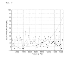
- FIG. 3 is a graph showing the filtering characteristics of the time domain auditory filter.
- the peak sound pressure is a value measured in the case where the masker is white noise, that is, the impulse signal.
- the time domain auditory filter 120 is operated through largely two mechanisms.
- the post-masking effect is shown by a curved line (hereinafter, "line 1") including a circle in FIG. 3 .
- line 1 When the masker is white noise in the frequency domain, the maskee is indicated by a pressure impulse having a bell shape.
- the pressure impulse having the bell shape serves as the "specific threshold” determining whether there is masking in each time delay shown on the horizontal axis.
- the longer the time from the end of the masker being a signal wanting to obtain to the start of the succeeding signal the smaller the threshold becomes.
- the time delay becomes short, even though the magnitude in the succeeding signal is considerable, it is buried in the masker so that the signal having a smaller magnitude than the threshold may be disregarded.
- the pressure ratio (specific threshold) of the vertical axis is about 0.28. This means that when the masker ends and the maskee starts after the time delay of 10 msec, if the peak pressure ratio of the maskee is equal to or less than 0.28, it is not sensed by the human auditory sense. If the peak pressure ratio of the succeeding signal exceeds 0.28, it will be sensed by the human auditory sense. Therefore, since the signal having the peak pressure ratio of 0.28 or less is masked by the post-masking effect, even though it is removed by the time domain auditory filter 120, it does not affect the entire sound field generation.
- the pressure impulse in the bell shape can be approximated as represented by the following Equation according to a time constant ⁇ .
- a axp exp ⁇ t / ⁇ (where a axp is an approximate value, and ⁇ is a time constant).
- the other is a gap detection threshold (hereinafter, referred to as "GDT") mechanism.
- the GDT is shown by a straight dotted line and a portion of a curved line (hereinafter, "line 2") in FIG. 3 .
- the line 2 follows the straight dotted line when ⁇ t is 4msec or less and follows the line 1 when ⁇ t is 4msec or more.
- This is represented by a function according to a bandwidth of a white noise channel and can be explained on an extension of the post masking effect. In other words, as the time delay is short, even though the succeeding signal has considerably large sound pressure, it is buried in the masker so that the succeeding signal and the masker cannot be discriminated at the human auditory level.
- Such an effect remarkably indicates as the time delay is short and a phenomenon that can not be sensed by the human auditory sense occurs regardless of the magnitude in the succeeding signal at a point where time delay is the same as GDT.
- the magnitude in the succeeding signal from 0 msec to GDT is larger than the sound pressure of the masker, even though the sound pressure exceeds the threshold, the succeeding signal is masked by the masker and therefore, even when it is removed, it does not affect the sound field generation.
- the distinct division of the GDT mechanism region and the post-masking effect mechanism based on GDT may involve slight risks.
- a method of reducing the GDT mechanism region and widening the post-masking effect mechanism region may be used.
- the margin is set to 1 msec. In other words, GDT is 5 msec, but the GDT mechanism region is set to 0 to 4 msec by securing the margin of 1 msec and the post-masking effect mechanism is set after 4 msec.
- the time domain auditory filter 120 may be implemented only by the post-masking effect mechanism. However, when the time delay is short in the post-masking effect mechanism, since the phenomenon that all the succeeding signals are masked occurs regardless of the threshold, it is more preferable that the useless signals are removed as maximally as possible to reduce the computational complexity and the GDT mechanism is added to the post-masking effect mechanism to implement the time domain auditory filter 120.
- the time domain auditory filter 120 implemented as above is operated as follows. When the time delay is within 4 msec, the time domain auditory filter 120 removes all signals equal to or less than the sound pressure of the masker, among the succeeding signals.
- the time domain auditory filter 120 passes the succeeding signals in the case where they exceed the specific threshold in the corresponding time delay and removes the succeeding signals in the case where they are equal to or less than the specific threshold.
- the time domain auditory filter 120 adaptively corresponds to the time delay of RIR to reflect the human auditory characteristic, thereby reducing the computational complexity of the sound field generating apparatus.
- the second fast Fourier transformer 130 performs the fast Fourier transform on each RIR block passing through the time domain auditory filter 120 and transforms them into the frequency domain.
- the multiplier 140 performs a function of multiplying each input signal block transformed into the frequency domain through the first fast Fourier transformer 110 by each RIR block transformed into the frequency domain through the second fast Fourier transformer 130. Since a convolution operation of the impulse response and the input signal in the time domain is equivalent to the multiplication of the impulse response and the input signal in the frequency domain, the multiplier 140 performs a simple operation, which is the multiplication of each corresponding block, to reflect actual sound space characteristic to the input signal blocks corresponding to the sound sources, thereby outputting each signal block 145 added with the sound field effect.
- the frequency domain auditory filter 150 receives each signal block 145 via the multiplier 140 to remove inaudible data through the human auditory sense depending on the frequency, which is then input to the block remover 160.
- the filtering by the time domain auditory filter 120 is directly performed on the RIR block 115, while the filtering by the frequency domain auditory filter 150 is performed on the signal block that the RIR block and the input signal block are multiplied in the frequency domain.
- FIG. 4 is a graph showing the human auditory characteristic in the frequency domain for implementing the frequency domain auditory filter according to a preferred embodiment of the invention.
- a horizontal axis indicates a frequency [Hz] and a vertical axis indicates a sound pressure level [dBL] in a state where there is no background noise.
- a curved line indicates threshold, a circle (hereinafter, "circle 1") above a curved line indicates audible data, a circle (hereinafter, "circle 2”) below a curved line including a curved line indicates inaudible data.
- each signal block 145 involves useless data based on the human auditory sense even in the frequency domain. Therefore, as shown in FIG. 4 , the frequency domain auditory filter 150 is implemented reflecting hearing threshold in quiet in the state where there is no background noise. The possibility to listen to the signal in the frequency domain may be determined as a function for "threshold in the state where there is no background noise" (hereinafter, referred to as "threshold") Tq(f)[dB].
- threshold the threshold in the frequency domain auditory filter 150 to pass data (circle 2 in FIG. 4 ) having the sound pressure level larger than the threshold and to filter data (circle 1 in FIG.
- Y P aud [k] means the sound pressure level of the block P having audible data at a k th sample and Y p [k] means the sound pressure level of the block P at the k th sample.
- the block remover 160 removes the signal blocks having a lower value than the average sound pressure level of the background noise blocks having the same length as the signal block, among each signal block output from the frequency-region auditory filter 150. There is a difference in that the time domain auditory filter 120 and the frequency domain auditory filter 150 filters the signals in a data unit while the block remover 160 filters the signals in a block unit.
- the operation of the block remover 160 is represented by the following Equation.
- Y out P [ k ] means the sound pressure level of the output block P at a k th sample
- BN means the background noise having the same length as the block P
- N means the length of the output block in the frequency domain.
- Equation 3 whether the given output signal blocks are maintained is determined by comparing them with the average sound pressure level of the background noise. In other words, when the average sound pressure level of the corresponding signal blocks is larger than the average sound pressure level of the background noise, the corresponding blocks are maintained as they are as the audible blocks and otherwise, the corresponding blocks are removed. In other words, the signal blocks having a lower level than the level of the background noise blocks among the output signal blocks are buried in the background noise so that they cannot be listened based on the human auditory sense. As a result, such blocks are removed through the block remover 160, making it possible to reduce the computational complexity and prevent the sound quality distortion.
- the inaudible data depending on the frequency in the signals multiplying the RIR by the input signal in the frequency domain are removed through the frequency domain auditory filter 150.
- the signal blocks having a lower level than the level of the background noise block among the signal blocks output from the frequency domain auditory filter 150 are removed through the block remover 160.
- the performance of the sound field generating apparatus is determined by the computational complexity, wherein the computational complexity is based on the number of multiplication operations which affects the power consumption required for processing in a digital signal processor.
- the block convolution according to the preferred embodiment of the invention to which the time domain auditory filter and the frequency domain auditory filter are applied shows the remarkable reduction of the computational complexity, regardless of kinds of systems (bathroom and large room) and sound source signals (barking of a dog, live voice, music).
- the reduction of the computational complexity means that the processing speed can be increased, the inexpensive processor and the small-capacity memory can be applied, and the real-time sound field generating system can be appropriately implemented.
- FIG. 5 is a flow chart of a method of generating a sound field according to the preferred embodiment of the invention.
- the method of generating a sound field includes a step (S10) of performing a fast Fourier transform on each input signal block to transform them into a frequency domain; a step (S20) of performing an auditory filtering on each RIR block in a time domain; a step (S30) of performing the fast Fourier transform on each RIR block subjected to the auditory filtering in the time domain to transform them into a frequency domain; a step (S40) of multiplying each input signal block transformed into the frequency domain by each RIR block; a step (S50) of performing the auditory filtering on each of the multiplied signal blocks in the frequency domain; a step (S60) of removing signal blocks having an average sound pressure level lower than an average sound pressure level of background noise blocks having the same length as the signal block, among the signal blocks subjected to the auditory filtering in the frequency domain; a step (S70) of performing an inverse fast Fourier transform on each of the passed signal blocks without being removed
- the step S10 is performed through the first fast Fourier transformer 110.
- the step S20 is performed in the time domain auditory filter 120.
- the filter 120 receives each RIR block in the time domain to filter the signals, which have the sound pressure equal to or less than the specific threshold at the specific time delay ⁇ t and thus, are not sensed by the human auditory sense and filters the signals that can not be sensed by the human auditory sense even when they exceeds the threshold, unless they are larger than the sound pressure of the masker in the case where the time delay ⁇ t is within the specific time gap.
- the step S30 is performed through the second fast Fourier transformer 130.
- the step S40 is performed through the multiplier 140.
- the step S50 is performed in the frequency domain auditory filter 150, which removes the inaudible data through the human auditory sense depending on the frequency for each signal block.
- the step S60 is performed through the block remover 160.
- the step S70 is performed through the inverse fast Fourier transformer 170.
- the sound field generating apparatus is mounted on a sounder to lower the sounder price and enhance its performance and can be applied to application fields using the sound convolution, including a three-dimensional virtual acoustic field.
Landscapes
- Physics & Mathematics (AREA)
- Engineering & Computer Science (AREA)
- Acoustics & Sound (AREA)
- Signal Processing (AREA)
- Soundproofing, Sound Blocking, And Sound Damping (AREA)
- Stereophonic System (AREA)
Applications Claiming Priority (1)
| Application Number | Priority Date | Filing Date | Title |
|---|---|---|---|
| KR2007084521 | 2007-08-22 |
Publications (2)
| Publication Number | Publication Date |
|---|---|
| EP2028883A2 true EP2028883A2 (de) | 2009-02-25 |
| EP2028883A3 EP2028883A3 (de) | 2012-11-28 |
Family
ID=40032875
Family Applications (1)
| Application Number | Title | Priority Date | Filing Date |
|---|---|---|---|
| EP08104920A Withdrawn EP2028883A3 (de) | 2007-08-22 | 2008-07-30 | Schallfeldgenerator und Verfahren zur Erzeugung eines Schallfeldes damit |
Country Status (1)
| Country | Link |
|---|---|
| EP (1) | EP2028883A3 (de) |
Cited By (1)
| Publication number | Priority date | Publication date | Assignee | Title |
|---|---|---|---|---|
| CN113470628A (zh) * | 2021-07-14 | 2021-10-01 | 青岛信芯微电子科技股份有限公司 | 一种语音识别方法及装置 |
Family Cites Families (1)
| Publication number | Priority date | Publication date | Assignee | Title |
|---|---|---|---|---|
| DE19545623C1 (de) * | 1995-12-07 | 1997-07-17 | Akg Akustische Kino Geraete | Verfahren und Vorrichtung zur Filterung eines Audiosignals |
-
2008
- 2008-07-30 EP EP08104920A patent/EP2028883A3/de not_active Withdrawn
Cited By (2)
| Publication number | Priority date | Publication date | Assignee | Title |
|---|---|---|---|---|
| CN113470628A (zh) * | 2021-07-14 | 2021-10-01 | 青岛信芯微电子科技股份有限公司 | 一种语音识别方法及装置 |
| CN113470628B (zh) * | 2021-07-14 | 2024-05-31 | 青岛信芯微电子科技股份有限公司 | 一种语音识别方法及装置 |
Also Published As
| Publication number | Publication date |
|---|---|
| EP2028883A3 (de) | 2012-11-28 |
Similar Documents
| Publication | Publication Date | Title |
|---|---|---|
| EP2124485B1 (de) | Erweiterte Verarbeitung auf der Basis einer mit komplexer Exponentialfunktion modulierten Filterbank und adaptive Zeitsignalisierungsverfahren | |
| Wu et al. | A two-stage algorithm for one-microphone reverberant speech enhancement | |
| US9799318B2 (en) | Methods and systems for far-field denoise and dereverberation | |
| US20020147595A1 (en) | Cochlear filter bank structure for determining masked thresholds for use in perceptual audio coding | |
| JP2005530432A (ja) | 部屋における拡声器からの音声のデジタル等化方法、および、この方法の使用法 | |
| US8098846B2 (en) | Sound field generator and method of generating sound field using the same | |
| Zhou et al. | Speech dereverberation with a reverberation time shortening target | |
| US20160212564A1 (en) | Apparatus and Method for Compressing a Set of N Binaural Room Impulse Responses | |
| WO2006082868A2 (en) | Method and system for identifying speech sound and non-speech sound in an environment | |
| US20160174013A1 (en) | Sound spatialization with room effect | |
| EP2028883A2 (de) | Schallfeldgenerator und Verfahren zur Erzeugung eines Schallfeldes damit | |
| US20160269850A1 (en) | Sound spatialization with room effect, optimized in terms of complexity | |
| US20050223050A1 (en) | Efficient method and apparatus for convolution of input signals | |
| Shin et al. | Fast convolution method using perceptual redundancy for a sound field generator | |
| Axelson-Fisk | Caring More About EQ Than IQ: Automatic Equalizing of Audio Signals | |
| Torres et al. | Efficient structure for auralization using a wavelet-based HRTF model | |
| HK1245552B (en) | Advanced processing based on a complex-exponential-modulated filterbank | |
| HK1245553B (en) | Advanced processing based on a complex-exponential-modulated filterbank | |
| Jeon et al. | Complexity Reduction of Virtual Reverberation Filtering Based on Index-Based Convolution for Resource-Constrained Devices | |
| Giesbrecht et al. | Algorithmic Reverberation | |
| HK1152435A (en) | Advanced processing based on a complex-exponential-modulated filterbank and adaptive time signalling methods | |
| Wallin | Combining Acoustic Echo Cancellation and Suppression | |
| HK1245556B (en) | Advanced processing based on a complex-exponential-modulated filterbank | |
| HK1152434A (en) | Advanced processing based on a complex-exponential-modulated filterbank and adaptive time signalling methods |
Legal Events
| Date | Code | Title | Description |
|---|---|---|---|
| PUAI | Public reference made under article 153(3) epc to a published international application that has entered the european phase |
Free format text: ORIGINAL CODE: 0009012 |
|
| 17P | Request for examination filed |
Effective date: 20080730 |
|
| AK | Designated contracting states |
Kind code of ref document: A2 Designated state(s): AT BE BG CH CY CZ DE DK EE ES FI FR GB GR HR HU IE IS IT LI LT LU LV MC MT NL NO PL PT RO SE SI SK TR |
|
| AX | Request for extension of the european patent |
Extension state: AL BA MK RS |
|
| PUAL | Search report despatched |
Free format text: ORIGINAL CODE: 0009013 |
|
| AK | Designated contracting states |
Kind code of ref document: A3 Designated state(s): AT BE BG CH CY CZ DE DK EE ES FI FR GB GR HR HU IE IS IT LI LT LU LV MC MT NL NO PL PT RO SE SI SK TR |
|
| AX | Request for extension of the european patent |
Extension state: AL BA MK RS |
|
| RIC1 | Information provided on ipc code assigned before grant |
Ipc: H04S 7/00 20060101AFI20121022BHEP |
|
| AKX | Designation fees paid |
Designated state(s): DE FR GB |
|
| STAA | Information on the status of an ep patent application or granted ep patent |
Free format text: STATUS: THE APPLICATION IS DEEMED TO BE WITHDRAWN |
|
| 18D | Application deemed to be withdrawn |
Effective date: 20130529 |