EP2028605A1 - Detection method for symmetric patterns - Google Patents
Detection method for symmetric patterns Download PDFInfo
- Publication number
- EP2028605A1 EP2028605A1 EP07016308A EP07016308A EP2028605A1 EP 2028605 A1 EP2028605 A1 EP 2028605A1 EP 07016308 A EP07016308 A EP 07016308A EP 07016308 A EP07016308 A EP 07016308A EP 2028605 A1 EP2028605 A1 EP 2028605A1
- Authority
- EP
- European Patent Office
- Prior art keywords
- image
- symmetry
- gradient
- image area
- computer program
- Prior art date
- Legal status (The legal status is an assumption and is not a legal conclusion. Google has not performed a legal analysis and makes no representation as to the accuracy of the status listed.)
- Withdrawn
Links
Images


Classifications
-
- G—PHYSICS
- G06—COMPUTING; CALCULATING OR COUNTING
- G06V—IMAGE OR VIDEO RECOGNITION OR UNDERSTANDING
- G06V20/00—Scenes; Scene-specific elements
- G06V20/50—Context or environment of the image
- G06V20/56—Context or environment of the image exterior to a vehicle by using sensors mounted on the vehicle
- G06V20/58—Recognition of moving objects or obstacles, e.g. vehicles or pedestrians; Recognition of traffic objects, e.g. traffic signs, traffic lights or roads
- G06V20/582—Recognition of moving objects or obstacles, e.g. vehicles or pedestrians; Recognition of traffic objects, e.g. traffic signs, traffic lights or roads of traffic signs
-
- G—PHYSICS
- G06—COMPUTING; CALCULATING OR COUNTING
- G06V—IMAGE OR VIDEO RECOGNITION OR UNDERSTANDING
- G06V10/00—Arrangements for image or video recognition or understanding
- G06V10/20—Image preprocessing
- G06V10/25—Determination of region of interest [ROI] or a volume of interest [VOI]
Definitions
- the present invention relates to a method for detecting a preferably associated with a roadway symmetrical object known form, in particular traffic sign, in an image of the environment in the field of view of a particularly arranged on a motor vehicle image pickup device.
- Systems for traffic sign recognition can be used to inform the driver of a motor vehicle about the traffic signs on the road, for example by projecting a graphic representation of a road sign detected on the roadway via a head-up display on the windscreen of the motor vehicle.
- traffic sign recognition systems may also be used as driver assistance systems, for example to automatically reduce the vehicle speed to the maximum permitted speed in the event of a speeding violation.
- a traffic sign recognition can be carried out in two stages, for example.
- a first stage detection
- the second stage classification
- Such a traffic sign recognition which is performed by a data processing device, however, requires a high computational effort, which leads to a high computation time. In addition, the robustness of such traffic sign recognition is insufficient.
- the invention has for its object to provide a way to shorten the computing time for the detection of symmetrical objects and / or to increase the robustness of such detection.
- This object is achieved by a method of the type mentioned, in which by means of the particular digital image pickup device, a particular digital image is recorded in the captured image or an image generated by an image processing from the captured image at least one pixel image area, each one predetermined amount of symmetry is exceeded, or a part thereof is determined on the basis of the at least one image area or the part thereof for a subsequent shape recognition in each case a relevant image detail is determined, and only in the at least one relevant image section in each case the shape recognition is performed to a potential Illustration of the symmetrical object to detect.
- the detection of the symmetrical object can be divided into two process steps.
- the relevant image detail may be, for example, the assigned image region or an area that includes the associated image region provided with an additional tolerance region.
- a shape recognition is then carried out exclusively in the relevant image sections.
- shape recognition methods known per se can be used, for example a Hough transformation for the recognition of circles and / or a method for the recognition of regular polygons, as described in US Pat Barnes et al., "Regular Polygon Detection", Tenth IEEE International Conference on Computer Vision (ICCV), 778, 2005 is described.
- the symmetry detection which precedes the shape detection, makes it possible to considerably shorten the computing time for the shape detection, since this then no longer has to be performed over the entire image, but can be limited to a few relevant image sections.
- each of the image areas or each of the parts thereof already contains a prediction about the expected size of the image of a symmetrical object, the expected size resulting directly from the size of the respective image area or part thereof.
- the additional symmetry detection requires a comparatively small computing time, which is exceeded many times over by the gain in computing time in the shape detection.
- the robustness of the total detection is increased by the upstream symmetry detection.
- the at least one image area or the part thereof is determined in an image generated by an image processing, wherein an edge detection or edge detection is performed to produce the processed image.
- edge detection methods known per se can be used, for example known edge filters such as the Sobel operator.
- the generated image is preferably a binary edge image or a gradient image in which the edges of the images of the symmetrical objects, insofar as they are present in the recorded image, are highlighted.
- the subsequent symmetry detection can then be performed on the basis of the gradient image or the binary edge image, whereby the computing time for the symmetry detection can be reduced.
- a gradient image this is an image in which the pixels each have a gradient vector, ie a gradient value and a gradient direction.
- the symmetry of a picture of an object in a recorded image in particular in a recorded gray scale image or in a gray value image generated from a recorded image, can be disturbed by illumination inhomogeneities. For example, in a lateral light incidence different areas of the image appear different bright. A gradient image or binary edge image is less sensitive to such interference. This further increases the robustness of the total detection.
- the symmetry measure is determined by comparing the gradient vectors of the image points of the gradient image which are opposite each other with respect to a line. This makes it possible to reliably detect symmetries, since the gradient directions of the respective pixels can also be taken into account in the comparison of the opposing pixels, so that their gradient directions are not at least approximate for opposite pixels which are identical or similar in their gradient values are mirror-symmetrically oriented to the line, resulting in a respect to the respective pixels low symmetry value. In principle, however, any other and / or known from the prior art method can be used to determine the symmetry measure.
- the at least one image area in each case has a mirror symmetry, in particular with respect to a preferably vertical symmetry line or axis.
- a mirror symmetry in particular with respect to a preferably vertical symmetry line or axis.
- the determination of the at least one image area or the part thereof is carried out only in a selected region or "region of interest" of the recorded or generated image.
- the determination of the at least one image region or of the part thereof can thus be preceded by a method step which pre-selects a region in which symmetrical objects to be detected can even occur.
- the non-selected region of the recorded or generated image however, no symmetrical objects are to be expected, so that a detection need not be carried out here either.
- the selected region and / or the non-selected region may be formed by a plurality of non-contiguous subregions.
- a method of determining a selected region is, for example, in the European patent application filed with the European Patent Office on July 30, 2007, with the application number 07 014 924.0 and the term "method for recognition of an article", the contents of which are hereby incorporated by reference into this application.
- the determination of the at least one image region or of the part thereof and / or the determination of the at least one relevant image detail is carried out taking into account a prediction of the expected size of the image of the object.
- the computing time for determining the at least one image area or the part thereof and / or for the subsequent shape detection can be reduced.
- the prediction can directly result from the size of the respective image area or part thereof, as described above.
- Another method of predicting the expected The size of the image of the article is shown in the aforementioned European patent application filed with the European Patent Office on 30 July 2007, with the application number 07 014 924.0 and the term "method for recognition of an article", the contents of which are hereby incorporated by reference into this application.
- Another object of the invention is a computer program with program code means to perform the method described above, when the program is executed on a computer or a corresponding arithmetic unit.
- the invention also relates to a computer program product with program code means which are stored on a computer-readable data carrier in order to carry out the method described above when the computer program is executed on a computer or a corresponding computing unit.
- a computer is understood to mean any data processing device with which the method can be executed.
- these may include digital signal processors and / or microprocessors, with which the method is carried out in whole or in part.
- the subject matter of the invention is an apparatus for detecting a symmetrical object of known form, in particular a traffic sign, assigned to a roadway, in an image of the surroundings in the field of vision of an image pickup device, in particular arranged on a motor vehicle, with a camera device for taking a picture, and with a data processing device, the is designed to carry out the method described above.
- Fig. 1 the detection stage of a method for traffic sign recognition is shown.
- a gray value image of the surroundings is first recorded in the field of vision of a digital video camera arranged on a motor vehicle.
- a color image are recorded, which is then converted into a gray scale image.
- the gray scale image is subjected to edge detection by means of a Sobel operator, resulting in a gradient image.
- the gradient image is characterized in that each pixel of the gradient image has a gradient vector, i. a gradient value and a gradient direction.
- a selected region region of interest is determined in the gray value image or the gradient image, in which traffic signs can basically occur. It is assumed that no traffic signs can occur in the non-selected region.
- the determination of the selected region is basically known and described, for example, in the aforementioned European Patent Application (Application No. 07 014 924.0).
- a selected method step 15 vertical lines of symmetry are searched for image areas in the selected region of the gradient image, each of which exceeds a predetermined level of horizontal mirror symmetry, as described below with reference to FIG Fig. 2 is explained in more detail.
- Each of the vertical symmetry lines is then assigned a relevant image detail from the gradient image.
- the respective relevant image section substantially corresponds to that image area for which the respective symmetry line has been determined, but is spatially expanded in relation to it by a tolerance range.
- a shape detection is performed.
- a shape detection in a gradient image for example by means of a Hough transformation is basically known from the prior art.
- the shape detection is facilitated by the fact that the relevant image detail is provided in each case with an expected at this point of the gradient image size of a traffic sign.
- the size to be expected is determined by the size of the respective vertical line of symmetry and a prediction of the size to be expected in the region of the respective image detail according to the method described in the aforementioned European patent application (application number 07 014 924.0 ).
- each column of the gradient image within the selected region is checked to see if the respective column or a portion thereof represents a vertical line of symmetry for a specific image area.
- Fig. 2 illustrates in which a plurality of contiguous, arranged in rows and columns pixels 19 are shown.
- each pixel of column 21 located within the selected region is examined to see if the row associated with each pixel has horizontal mirror symmetry within the selected region.
- Fig. 2 illustrated by the pixel 19 'of the column 21, wherein pixel 19' in line 23 is arranged.
- two pixels one of which is located on the left and one on the right of the pixel 19', have the same distance r from the pixel 19 ' , compared with each other.
- the result is a correspondingly high value for the product of the two gradient values ⁇ 1 , ⁇ 2 m .
- a high value for this product suggests a high degree of mirror symmetry of the two pixels with respect to column 21.
- the two pixels each have a high gradient value ⁇ 1 , ⁇ 2 m
- the gradient directions of the two pixels with respect to the column 21 are not mirror-symmetrical with respect to one another, ie, the two belong Pixels not exactly mirror-symmetrical edges, results in a correspondingly small cos value (less than 1), so that the vector product and thus the degree of mirror symmetry of the two pixels is reduced.
- the vector product is formed for all pixel pairs of line 23 within the interval [r min , r max ]. Subsequently, the vector products are added. If the sum of the vector products of the pixel pairs of the row 23 within the interval [r min , r max ] is above a threshold value, the pixel 19 'is recognized as the center of symmetry for the pixels of the row 23 within the interval [r min , r max ].
- Fig. 3 is shown in simplified form, generated from a recorded by means of the digital video camera gray scale image gradient image 25, which shows a gantry 27 over a highway, wherein on the gantry 27, three traffic signs 29 are mounted.
- a gantry 27 over a highway
- three traffic signs 29 are mounted in the right border area of the gradient image 25 .
- bushes 31 located to the right of the highway are indicated.
- the maps 29 of the traffic signs in the gradient image 25 are associated with symmetry lines 33.
- further lines of symmetry 35 are shown, which although symmetrical image areas or image sections, but no images are assigned by traffic signs. The symmetry lines were each determined as described above.
- the subsequent shape detection 17 By means of the subsequent shape detection 17, the round or triangular shapes of the images 29 of the traffic signs can then be recognized. For the symmetry lines 35, however, the subsequent shape detection 17 or a subsequent classification step will determine that no traffic signs are depicted in the image areas or image sections assigned to the symmetry lines 35.
- the symmetry detection described above makes it possible to carry out traffic sign detection faster and with greater robustness.
Landscapes
- Engineering & Computer Science (AREA)
- Physics & Mathematics (AREA)
- General Physics & Mathematics (AREA)
- Multimedia (AREA)
- Theoretical Computer Science (AREA)
- Image Analysis (AREA)
- Traffic Control Systems (AREA)
- Image Processing (AREA)
Abstract
Description
Die vorliegende Erfindung betrifft ein Verfahren zur Detektion eines vorzugsweise einer Fahrbahn zugeordneten symmetrischen Gegenstandes bekannter Form, insbesondere Verkehrszeichens, in einem Bild der Umgebung im Sichtbereich einer insbesondere an einem Kraftfahrzeug angeordneten Bildaufnahmeeinrichtung.The present invention relates to a method for detecting a preferably associated with a roadway symmetrical object known form, in particular traffic sign, in an image of the environment in the field of view of a particularly arranged on a motor vehicle image pickup device.
Systeme zur Verkehrszeichenerkennung können dazu verwendet werden, den Fahrer eines Kraftfahrzeugs über die Verkehrszeichen an der Fahrbahn zu informieren, beispielsweise durch Projektion einer graphischen Repräsentation eines an der Fahrbahn detektierten Verkehrszeichens über ein Head-up Display auf die Frontscheibe des Kraftfahrzeugs. Systeme zur Verkehrszeichenerkennung können jedoch auch als Fahrerassistenzsysteme verwendet werden, beispielsweise um bei einer Geschwindigkeitsübertretung die Fahrgeschwindigkeit automatisch auf die zulässige Höchstgeschwindigkeit zu reduzieren.Systems for traffic sign recognition can be used to inform the driver of a motor vehicle about the traffic signs on the road, for example by projecting a graphic representation of a road sign detected on the roadway via a head-up display on the windscreen of the motor vehicle. However, traffic sign recognition systems may also be used as driver assistance systems, for example to automatically reduce the vehicle speed to the maximum permitted speed in the event of a speeding violation.
Für die Verkehrszeichenerkennung werden Kameras eingesetzt, die die Umgebung vor dem Kraftfahrzeug aufnehmen und auf das Vorhandensein von Verkehrszeichen hin untersuchen. Eine Verkehrszeichenerkennung kann beispielsweise zweistufig durchgeführt werden. In einer ersten Stufe (Detektion) geht es dann darum, über eine Merkmalsextraktion potentielle Kandidaten für Abbildungen von Verkehrszeichen in einem aufgenommenen Bild aufzufinden. Dies kann beispielsweise mittels einer Hough-Transformation, welche der Erkennung von geometrischen Formen dient, oder mittels einer Farbsegmentierung, bei der zusammenhängende Flächen gleicher Farbe erkannt werden, erfolgen. Die zweite Stufe (Klassifikation) hat zur Aufgabe, zunächst festzustellen, ob es sich bei dem jeweiligen Kandidaten tatsächlich um eine Abbildung eines Verkehrszeichens handelt, und im bejahenden Falle dann den Typ des abgebildeten Verkehrszeichens zu bestimmen. Dies kann beispielsweise mittels eines Template Matching (Maskenvergleich) erfolgen.For the traffic sign recognition cameras are used, which record the environment in front of the vehicle and examine for the presence of traffic signs out. A traffic sign recognition can be carried out in two stages, for example. In a first stage (detection) it is then about finding a feature extraction potential candidates for images of traffic signs in a recorded image. This can be done, for example, by means of a Hough transformation, which serves to recognize geometric shapes, or by means of color segmentation, in which contiguous surfaces be recognized the same color done. The second stage (classification) has the task of first determining whether the respective candidate is actually a representation of a traffic sign, and then, in the affirmative case, of determining the type of traffic sign mapped. This can be done for example by means of a template matching (mask comparison).
Eine derartige Verkehrszeichenerkennung, welche von einer Datenverarbeitungseinrichtung ausgeführt wird, erfordert jedoch einen hohen Rechenaufwand, welcher zu einer hohen Rechenzeit führt. Darüber hinaus ist die Robustheit einer derartigen Verkehrszeichenerkennung unzureichend.Such a traffic sign recognition, which is performed by a data processing device, however, requires a high computational effort, which leads to a high computation time. In addition, the robustness of such traffic sign recognition is insufficient.
Der Erfindung liegt die Aufgabe zugrunde, eine Möglichkeit anzugeben, die Rechenzeit für die Detektion von symmetrischen Gegenständen zu verkürzen und/oder die Robustheit einer derartigen Detektion zu erhöhen.The invention has for its object to provide a way to shorten the computing time for the detection of symmetrical objects and / or to increase the robustness of such detection.
Diese Aufgabe wird durch ein Verfahren der eingangs genannten Art gelöst, bei dem mittels der insbesondere digitalen Bildaufnahmeeinrichtung ein insbesondere digitales Bild aufgenommen wird, in dem aufgenommenen Bild oder einem durch eine Bildbearbeitung aus dem aufgenommenen Bild erzeugten Bild wenigstens ein Bildpunkte umfassender Bildbereich, der jeweils ein vorgegebenes Maß an Symmetrie überschreitet, oder ein Teil hiervon ermittelt wird, anhand des wenigstens einen Bildbereichs oder des Teils hiervon für eine nachfolgende Formerkennung jeweils ein relevanter Bildausschnitt bestimmt wird, und lediglich in dem wenigstens einen relevanten Bildausschnitt jeweils die Formerkennung durchgeführt wird, um eine potentielle Abbildung des symmetrischen Gegenstandes zu detektieren.This object is achieved by a method of the type mentioned, in which by means of the particular digital image pickup device, a particular digital image is recorded in the captured image or an image generated by an image processing from the captured image at least one pixel image area, each one predetermined amount of symmetry is exceeded, or a part thereof is determined on the basis of the at least one image area or the part thereof for a subsequent shape recognition in each case a relevant image detail is determined, and only in the at least one relevant image section in each case the shape recognition is performed to a potential Illustration of the symmetrical object to detect.
Die Detektion des symmetrischen Gegenstandes kann in zwei Verfahrensschritte eingeteilt werden.The detection of the symmetrical object can be divided into two process steps.
Da symmetrische Gegenstände in einem Bild zu entsprechenden symmetrischen Bildbereichen führen, wird in einem ersten Verfahrensschritt in dem aufgenommenen Bild oder dem von dem aufgenommenen Bild abgeleiteten Bild nach solchen Bildbereichen gesucht, die zumindest ein gewisses Mindestmaß an Symmetrie aufweisen. Aus einem derartigen Bildbereich oder Teil hiervon wird dann der jeweils zugeordnete relevante Bildausschnitt bestimmt. Insbesondere handelt es sich bei dem Teil des Bildbereichs um eine bevorzugt vertikale Symmetrielinie des Bildbereichs. Bei dem relevanten Bildausschnitt kann es sich beispielsweise um den zugeordneten Bildbereich oder um einen Bereich handeln, der den mit einem zusätzlichen Toleranzbereich versehenen zugeordneten Bildbereich umfasst.Since symmetrical objects in an image lead to corresponding symmetrical image areas, in a first method step in the recorded image or the image derived from the captured image, those image areas are sought that have at least a certain minimum of symmetry. From such an image area or part thereof, the respectively associated relevant image detail is then determined. In particular, the part of the image area is a preferably vertical symmetry line of the image area. The relevant image detail may be, for example, the assigned image region or an area that includes the associated image region provided with an additional tolerance region.
In einem zweiten Verfahrensschritt wird dann ausschließlich in den relevanten Bildausschnitten eine Formerkennung durchgeführt. Zur Formerkennung können an sich bekannte Verfahren verwendet werden, beispielsweise eine Hough-Transformation zur Erkennung von Kreisen und/oder ein Verfahren zur Erkennung von regulären Polygonen, wie es in
Über die Formerkennung können potentielle Abbildungen der insbesondere unbewegten symmetrischen Gegenstände bekannter Form ermittelt werden, welche dann in einer nachfolgenden Klassifikation, beispielsweise mittels Template Matching, verifiziert und erkannt werden können.About the shape detection potential images of particular unmoved symmetrical objects known form can be determined, which can then be verified and recognized in a subsequent classification, for example by means of template matching.
Die der Formdetektion vorgeschaltete Symmetriedetektion ermöglicht, die Rechenzeit für die Formdetektion erheblich zu verkürzen, da diese dann nicht mehr über das gesamte Bild hinweg durchgeführt werden muss, sondern auf wenige relevante Bildausschnitte beschränkt werden kann. Darüber hinaus enthält ein jeder der Bildbereiche oder ein jedes der Teile hiervon bereits eine Vorhersage über die zu erwartende Größe der Abbildung eines symmetrischen Gegenstandes, wobei sich die zu erwartende Größe unmittelbar aus der Größe des jeweiligen Bildbereichs oder Teils hiervon ergibt. Die zusätzliche Symmetriedetektion erfordert eine vergleichsweise geringe Rechenzeit, die von dem Gewinn an Rechenzeit bei der Formdetektion um ein Vielfaches übertroffen wird. Darüber hinaus wird durch die vorgeschaltete Symmetriedetektion die Robustheit der Gesamtdetektion erhöht.The symmetry detection, which precedes the shape detection, makes it possible to considerably shorten the computing time for the shape detection, since this then no longer has to be performed over the entire image, but can be limited to a few relevant image sections. In addition, each of the image areas or each of the parts thereof already contains a prediction about the expected size of the image of a symmetrical object, the expected size resulting directly from the size of the respective image area or part thereof. The additional symmetry detection requires a comparatively small computing time, which is exceeded many times over by the gain in computing time in the shape detection. In addition, the robustness of the total detection is increased by the upstream symmetry detection.
Bevorzugt wird der wenigstens eine Bildbereich oder der Teil hiervon in einem durch eine Bildbearbeitung erzeugten Bild ermittelt, wobei zur Erzeugung des bearbeiteten Bildes eine Kantenerkennung oder Kantendetektion durchgeführt wird. Zur Kantendetektion können an sich bekannte Verfahren verwendet werden, beispielsweise bekannte Kantenfilter wie der Sobel-Operator. Bei dem erzeugten Bild handelt es sich bevorzugt um ein binäres Kantenbild oder ein Gradientenbild, in dem die Kanten der Abbildungen der symmetrischen Gegenstände, soweit solche in dem aufgenommenen Bild vorhanden sind, hervorgehoben sind. Die nachfolgende Symmetriedetektion kann dann anhand des Gradientenbildes oder des binären Kantenbildes durchgeführt werden, wodurch die Rechenzeit für die Symmetriedetektion reduziert werden kann. Bei einem Gradientenbild, handelt es sich um ein Bild, in dem den Bildpunkten jeweils ein Gradientenvektor, d.h. ein Gradientenwert und eine Gradientenrichtung, zugeordnet ist.Preferably, the at least one image area or the part thereof is determined in an image generated by an image processing, wherein an edge detection or edge detection is performed to produce the processed image. For edge detection methods known per se can be used, for example known edge filters such as the Sobel operator. The generated image is preferably a binary edge image or a gradient image in which the edges of the images of the symmetrical objects, insofar as they are present in the recorded image, are highlighted. The subsequent symmetry detection can then be performed on the basis of the gradient image or the binary edge image, whereby the computing time for the symmetry detection can be reduced. In the case of a gradient image, this is an image in which the pixels each have a gradient vector, ie a gradient value and a gradient direction.
Darüber hinaus kann die Symmetrie einer Abbildung eines Gegenstandes in einem aufgenommenen Bild, insbesondere in einem aufgenommenen Grauwertbild oder in einem aus einem aufgenommenen Bild erzeugten Grauwertbild, durch Beleuchtungsinhomogenitäten gestört werden. Beispielsweise können bei einem seitlichen Lichteinfall verschiedene Bereiche der Abbildung unterschiedlich hell erscheinen. Ein Gradientenbild oder binäres Kantenbild ist gegenüber derartigen Störungen weniger empfindlich. Hierdurch wird die Robustheit der Gesamtdetektion weiter erhöht.In addition, the symmetry of a picture of an object in a recorded image, in particular in a recorded gray scale image or in a gray value image generated from a recorded image, can be disturbed by illumination inhomogeneities. For example, in a lateral light incidence different areas of the image appear different bright. A gradient image or binary edge image is less sensitive to such interference. This further increases the robustness of the total detection.
Nach einer Ausgestaltung der Erfindung wird für den wenigstens einen Bildbereich jeweils das Symmetriemaß durch Vergleich der Gradientenvektoren der bezüglich einer Linie einander gegenüberliegenden Bildpunkte des Gradientenbildes bestimmt. Dies ermöglicht, Symmetrien zuverlässig zu erkennen, da bei dem Vergleich der einander gegenüberliegenden Bildpunkte auch die Gradientenrichtungen der jeweiligen Bildpunkte berücksichtigt werden können, so dass bei einander gegenüberliegenden Bildpunkten, die zwar in ihren Gradientenwerten übereinstimmen oder einander ähnlich sind, deren Gradientenrichtungen aber nicht zumindest annähernd spiegelsymmetrisch zu der Linie orientiert sind, ein bezüglich der jeweiligen Bildpunkte geringer Symmetriewert resultiert. Grundsätzlich kann zur Bestimmung des Symmetriemaßes jedoch auch jedes andere und/oder aus dem Stand der Technik bekannte Verfahren verwendet werden.According to one embodiment of the invention, for each of the at least one image region, the symmetry measure is determined by comparing the gradient vectors of the image points of the gradient image which are opposite each other with respect to a line. This makes it possible to reliably detect symmetries, since the gradient directions of the respective pixels can also be taken into account in the comparison of the opposing pixels, so that their gradient directions are not at least approximate for opposite pixels which are identical or similar in their gradient values are mirror-symmetrically oriented to the line, resulting in a respect to the respective pixels low symmetry value. In principle, however, any other and / or known from the prior art method can be used to determine the symmetry measure.
Bevorzugt weist der wenigstens eine Bildbereich jeweils eine Spiegelsymmetrie auf, insbesondere bezüglich einer bevorzugt vertikalen Symmetrielinie bzw. Achse. Dies ist insbesondere deshalb von Vorteil, da die meisten einer Fahrbahn zugeordneten symmetrischen Gegenstände, insbesondere runde oder dreieckige Verkehrszeichen, bezüglich einer vertikalen Achse symmetrisch bzw. spiegelsymmetrisch aufgebaut sind.Preferably, the at least one image area in each case has a mirror symmetry, in particular with respect to a preferably vertical symmetry line or axis. This is particularly advantageous because most of a roadway associated symmetrical objects, in particular round or triangular traffic signs are constructed symmetrically or mirror-symmetrically with respect to a vertical axis.
Nach einer anderen Ausgestaltung der Erfindung wird die Ermittlung des wenigstens einen Bildbereichs oder des Teils hiervon nur in einer ausgewählten Region oder "Region of Interest" des aufgenommenen oder erzeugten Bildes durchgeführt. Der Ermittlung des wenigstens eines Bildbereichs oder des Teils hiervon kann also ein Verfahrensschritt vorgeschaltet sein, der eine Region vorauswählt, in der zu detektierende symmetrische Gegenstände überhaupt vorkommen können. In der nicht ausgewählten Region des aufgenommenen bzw. erzeugten Bildes hingegen sind keine symmetrischen Gegenstände zu erwarten, so dass hier eine Detektion auch nicht durchgeführt zu werden braucht. Hierdurch kann die Rechenzeit für die nachfolgende Symmetriedetektion reduziert werden. Die ausgewählte Region und/oder die nicht ausgewählte Region kann durch mehrere nicht zusammenhängende Teilregionen gebildet sein. Ein Verfahren zur Bestimmung einer ausgewählten Region ist beispielsweise in der von der Anmelderin am 30. Juli 2007 beim Europäischen Patentamt eingereichten europäischen Patentanmeldung mit der Anmeldenummer
Bevorzugt wird die Ermittlung des wenigstens einen Bildbereichs oder des Teils hiervon und/oder die Bestimmung des wenigstens einen relevanten Bildausschnitts unter Berücksichtigung einer Vorhersage über die zu erwartende Größe der Abbildung des Gegenstandes durchgeführt. Hierdurch kann die Rechenzeit für die Ermittlung des wenigstens einen Bildbereichs oder des Teils hiervon und/oder für die nachfolgende Formdetektion reduziert werden. Die Vorhersage kann sich unmittelbar aus der Größe des jeweiligen Bildbereichs oder Teils hiervon ergeben, wie vorstehend beschrieben ist. Ein anderes Verfahren zur Vorhersage der zu erwartenden Größe der Abbildung des Gegenstandes ist in der vorgenannten, von der Anmelderin am 30. Juli 2007 beim Europäischen Patentamt eingereichten europäischen Patentanmeldung mit der Anmeldenummer
Weiterer Gegenstand der Erfindung ist ein Computerprogramm mit Programmcode-Mitteln, um das vorstehend beschriebene Verfahren durchzuführen, wenn das Programm auf einem Computer oder einer entsprechenden Recheneinheit ausgeführt wird.Another object of the invention is a computer program with program code means to perform the method described above, when the program is executed on a computer or a corresponding arithmetic unit.
Gegenstand der Erfindung ist auch ein Computerprogrammprodukt mit Programmcode-Mitteln, die auf einem computerlesbaren Datenträger gespeichert sind, um das vorstehend beschriebene Verfahren durchzuführen, wenn das Computerprogramm auf einem Computer oder einer entsprechenden Recheneinheit ausgeführt wird.The invention also relates to a computer program product with program code means which are stored on a computer-readable data carrier in order to carry out the method described above when the computer program is executed on a computer or a corresponding computing unit.
Unter einem Computer wird hierbei eine beliebige Datenverarbeitungsvorrichtung verstanden, mit der das Verfahren ausgeführt werden kann. Insbesondere können diese digitale Signalprozessoren und/oder Mikroprozessoren aufweisen, mit denen das Verfahren ganz oder in Teilen ausgeführt wird.In this case, a computer is understood to mean any data processing device with which the method can be executed. In particular, these may include digital signal processors and / or microprocessors, with which the method is carried out in whole or in part.
Schließlich ist Gegenstand der Erfindung eine Vorrichtung zur Detektion eines vorzugsweise einer Fahrbahn zugeordneten symmetrischen Gegenstandes bekannter Form, insbesondere Verkehrszeichens, in einem Bild der Umgebung im Sichtbereich einer insbesondere an einem Kraftfahrzeug angeordneten Bildaufnahmeeinrichtung, mit einer Kameraeinrichtung zur Aufnahme eines Bildes, und mit einer Datenverarbeitungseinrichtung, die zur Durchführung des vorstehend beschriebenen Verfahrens ausgebildet ist.Finally, the subject matter of the invention is an apparatus for detecting a symmetrical object of known form, in particular a traffic sign, assigned to a roadway, in an image of the surroundings in the field of vision of an image pickup device, in particular arranged on a motor vehicle, with a camera device for taking a picture, and with a data processing device, the is designed to carry out the method described above.
Weitere vorteilhafte Ausführungsformen der Erfindung sind in den Unteransprüchen, der Beschreibung und der Zeichnung angegeben.Further advantageous embodiments of the invention are specified in the subclaims, the description and the drawing.
Die Erfindung wird im Folgenden beispielhaft unter Bezugnahme auf die Zeichnung beschrieben.The invention will now be described by way of example with reference to the drawings.
Es zeigen, jeweils in schematischer Darstellung,
- Fig. 1
- ein Blockdiagramm, in dem mehrere Verfahrensschritte zur Detektion von symmetrischen Gegenständen dargestellt sind,
- Fig. 2
- Bildpunkte eines Bildbereichs zur Veranschaulichung der Bestimmung eines Symmetriemaßes, und
- Fig. 3
- ein aus einem mittels einer digitalen Videokamera aufgenom- menen Bild erzeugtes Gradientenbild, in dem vertikale Sym- metrielinien dargestellt sind.
- Fig. 1
- a block diagram, in which a plurality of method steps for the detection of symmetrical objects are shown,
- Fig. 2
- Pixels of an image area to illustrate the determination of a Symmetriemaßes, and
- Fig. 3
- a gradient image generated from an image recorded by means of a digital video camera, in which vertical symmetry lines are shown.
In
Hierzu wird in einem ersten Verfahrensschritt 11 zunächst ein Grauwertbild der Umgebung im Sichtbereich einer an einem Kraftfahrzeug angeordneten digitalen Videokamera aufgenommen. Grundsätzlich kann jedoch auch ein Farbbild aufgenommen werden, welches anschließend in ein Grauwertbild umgewandelt wird.For this purpose, in a
Danach wird das Grauwertbild in einem zweiten Verfahrensschritt 13 mittels eines Sobel-Operators einer Kantenerkennung unterzogen, wobei ein Gradientenbild resultiert. Das Gradientenbild zeichnet sich dadurch aus, dass jedem Bildpunkt bzw. Pixel des Gradientenbildes ein Gradientenvektor, d.h. ein Gradientenwert und eine Gradientenrichtung, zugeordnet ist. Zuvor oder anschließend wird in dem Grauwertbild oder dem Gradientenbild eine ausgewählte Region (Region of Interest) bestimmt, in der Verkehrszeichen grundsätzlich vorkommen können. Dabei wird davon ausgegangen, dass in der nicht ausgewählten Region keine Verkehrszeichen vorkommen können. Die Bestimmung der ausgewählten Region ist grundsätzlich bekannt und beispielsweise in der vorgenannten europäischen Patentanmeldung (Anmeldenummer 07 014 924.0) beschrieben.Thereafter, in a
Anschließend werden in einem dritten Verfahrensschritt 15 in der ausgewählten Region des Gradientenbildes vertikale Symmetrielinien für Bildbereiche gesucht, die jeweils ein vorgegebenes Maß an horizontaler Spiegelsymmetrie überschreiten, wie nachfolgend anhand von
Schließlich wird in einem vierten Verfahrensschritt 17, und zwar ausschließlich im Bereich der relevanten Bildausschnitte, welche die vertikalen Symmetrielinien umfassen, jeweils eine Formdetektion durchgeführt. Eine Formdetektion in einem Gradientenbild, beispielsweise mittels einer Hough-Transformation, ist aus dem Stand der Technik grundsätzlich bekannt. Die Formdetektion wird dabei dadurch erleichtert, dass der relevante Bildausschnitt jeweils mit einer an dieser Stelle des Gradientenbildes zu erwartenden Größe eines Verkehrszeichens versehen ist. Die zu erwartende Größe wird aus der Größe der jeweiligen vertikalen Symmetrielinie und einer Vorhersage über die zu erwartende Größe im Bereich des jeweiligen Bildausschnitts gemäß dem in der vorgenannten europäischen Patentanmeldung (Anmeldenummer
Um die vorgenannten Symmetrielinien zu finden, wird innerhalb der ausgewählten Region jede Spalte des Gradientenbildes daraufhin überprüft, ob die jeweilige Spalte oder ein Abschnitt hiervon eine vertikale Symmetrielinie für einen bestimmten Bildbereich darstellt. Dies ist in
Dies ist in
Dabei werden jeweils zwei von dem Pixel 19' gleichbeabstandete Pixel miteinander verglichen, deren Abstand in einem Intervall zwischen einem minimalen Abstand rmin und einem maximalen Abstand rmax zu dem Pixel 19' liegt. Die Grenzen rmin und rmax des Intervalls werden in Abhängigkeit von der Größe und Form der zu detektierenden Verkehrszeichen gewählt. Hierbei wird eine Vorhersage über die zu erwartende Größe von Verkehrszeichen, wie sie beispielsweise in der vorgenannten europäischen Patentanmeldung (Anmeldenummer
Der Vergleich der beiden jeweiligen Pixel, beispielsweise der beiden Pixel 19" oder 19"', erfolgt jeweils durch Bildung des Skalarprodukts aus dem Gradientenvektor ν1 des einen der beiden Pixel und einem Gradientenvektor ν2m , der durch Spiegelung des Gradientenvektors ν2 des anderen der beiden Pixel um eine vertikale Achse entstanden ist: 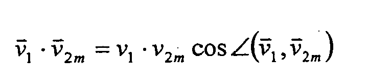
Gehören die beiden Pixel jeweils zu einer Kante, d.h. weisen die beiden Pixel jeweils einen hohen Gradientenwert ν1, ν2m auf, ergibt sich ein entsprechend hoher Wert für das Produkt aus den beiden Gradientenwerten ν1, ν2m . Ein hoher Wert für dieses Produkt lässt ein hohes Maß an Spiegelsymmetrie der beiden Pixel bezüglich der Spalte 21 vermuten. Weisen die beiden Pixel zwar jeweils einen hohen Gradientenwert ν1, ν2m auf, sind die Gradientenrichtungen der beide Pixel bezüglich der Spalte 21 jedoch nicht spiegelsymmetrisch zueinander orientiert, d.h. gehören die beiden Pixel nicht zu exakt spiegelsymmetrischen Kanten, ergibt sich ein entsprechend kleiner cos-Wert (kleiner 1), so dass auch das Vektorprodukt und damit das Maß an Spiegelsymmetrie der beiden Pixel reduziert wird.If the two pixels in each case belong to one edge, ie if the two pixels each have a high gradient value ν 1 , ν 2 m , the result is a correspondingly high value for the product of the two gradient values ν 1 , ν 2 m . A high value for this product suggests a high degree of mirror symmetry of the two pixels with respect to
Das Vektorprodukt wird für alle Pixelpaare der Zeile 23 innerhalb des Intervalls [rmin, rmax] gebildet. Anschließend werden die Vektorprodukte aufaddiert. Liegt die Summe der Vektorprodukte der Pixelpaare der Zeile 23 innerhalb des Intervalls [rmin, rmax] oberhalb eines Schwellwerts, wird das Pixel 19' als Symmetriezentrum für die Pixel der Zeile 23 innerhalb des Intervalls [rmin, rmax] erkannt.The vector product is formed for all pixel pairs of
Die in Spalte 21 über und unter dem Pixel 19' liegenden Pixel werden entsprechend untersucht. Dabei bilden zusammenhängende Pixel der Spalte 21, die jeweils als Symmetriezentrum erkannt wurden, eine Symmetrielinie im Sinne der vorliegenden Anmeldung, wobei die Symmetrielinie folglich einem Bildbereich zugeordnet ist, der ein vorgegebenes Maß an Symmetrie überschreitet. Der Robustheit des Verfahrens halber können bei der Bildung einer Symmetrielinie vereinzelt auch Pixel berücksichtigt werden, die nicht als Symmetriezentrum erkannt wurden.The pixels in
In
Mittels der nachfolgenden Formdetektion 17 können dann die runden bzw. dreieckigen Formen der Abbildungen 29 der Verkehrszeichen erkannt werden. Für die Symmetrielinien 35 hingegen wird die nachfolgende Formdetektion 17 oder eine nachfolgende Klassifikationsstufe feststellen, dass in den den Symmetrielinien 35 zugeordneten Bildbereichen bzw. Bildausschnitten keine Verkehrszeichen abgebildet sind.By means of the
Die vorstehend beschriebene Symmetriedetektion ermöglicht, eine Verkehrszeichendetektion schneller und mit einer höheren Robustheit durchzuführen.The symmetry detection described above makes it possible to carry out traffic sign detection faster and with greater robustness.
- 1111
- erster Verfahrensschrittfirst process step
- 1313
- zweiter Verfahrensschrittsecond process step
- 1515
- dritter Verfahrensschrittthird process step
- 1717
- vierter Verfahrensschrittfourth process step
- 1919
- Pixelpixel
- 2121
- Spaltecolumn
- 2323
- Zeilerow
- 2525
- Gradientenbildgradient
- 2727
- Schilderbrückegantry
- 2929
- Verkehrszeichenroad sign
- 3131
- Gebüschbushes
- 3333
- Symmetrielinieline of symmetry
- 3535
- Symmetrielinieline of symmetry
- rr
- Abstanddistance
- rmax r max
- maximaler Abstandmaximum distance
- rmin min
- minimaler Abstandminimum distance
- ν1 ν 1
- Gradientenvektorgradient vector
- ν2 ν 2
- Gradientenvektorgradient vector
- ν2m ν 2 m
- gespiegelter Gradientenvektormirrored gradient vector
- ν1 ν 1
- Betragamount
- ν2m ν 2 m
- Betragamount
Claims (10)
mittels der Bildaufnahmeeinrichtung ein Bild aufgenommen wird (11),
in dem aufgenommenen Bild oder einem durch eine Bildbearbeitung aus dem aufgenommenen Bild erzeugten Bild (25) wenigstens ein Bildpunkte (19) umfassender Bildbereich, der jeweils ein vorgegebenes Maß an Symmetrie überschreitet, oder ein Teil (33, 35) hiervon ermittelt wird (15),
anhand des wenigstens einen Bildbereichs oder des Teils (33, 35) hiervon für eine nachfolgende Formerkennung (17) jeweils ein relevanter Bildausschnitt bestimmt wird, und
lediglich in dem wenigstens einen relevanten Bildausschnitt jeweils die Formerkennung (17) durchgeführt wird, um eine potentielle Abbildung (29) des symmetrischen Gegenstandes zu detektieren.Method for detecting a symmetrical object of a known form, in particular a traffic sign, which is preferably assigned to a roadway, in an image (25) of the surroundings in the field of vision of an image pickup device, in particular arranged on a motor vehicle, in which
an image is taken by means of the image recording device (11),
in the recorded image or in an image (25) generated by image processing from the captured image (25) at least one image area (19), each exceeding a predetermined degree of symmetry, or a portion (33, 35) thereof is determined (15) .
on the basis of the at least one image area or of the part (33, 35) thereof for a subsequent shape recognition (17) in each case a relevant image detail is determined, and
only in the at least one relevant image section in each case the shape recognition (17) is performed in order to detect a potential image (29) of the symmetrical object.
dadurch gekennzeichnet,
dass zur Erzeugung des bearbeiteten Bildes (25) eine Kantenerkennung durchgeführt wird (13), wobei bevorzugt ein insbesondere Gradientenvektoren umfassendes Gradientenbild (25) oder ein binäres Kantenbild entsteht.Method according to claim 1,
characterized,
in that an edge detection is carried out (13) for producing the processed image (25), with a gradient image (25), which in particular comprises gradient vectors, or a binary edge image preferably being formed.
dadurch gekennzeichnet,
dass für den wenigstens einen Bildbereich jeweils das Maß an Symmetrie durch Vergleich der Gradientenvektoren der bezüglich einer Linie (33, 35) einander gegenüberliegenden Bildpunkte (19) des Gradientenbildes (25) bestimmt wird.Method according to claim 2,
characterized,
in each case the degree of symmetry is determined for the at least one image area by comparison of the gradient vectors of the pixels (19) of the gradient image (25) which are opposite each other with respect to a line (33, 35).
dadurch gekennzeichnet,
dass der wenigstens eine Bildbereich jeweils eine Spiegelsymmetrie aufweist, insbesondere bezüglich einer bevorzugt vertikalen Symmetrielinie (33, 35).Method according to one of the preceding claims,
characterized,
in that the at least one image area in each case has a mirror symmetry, in particular with respect to a preferably vertical symmetry line (33, 35).
dadurch gekennzeichnet,
dass die Ermittlung des wenigstens einen Bildbereichs oder des Teils (33, 35) hiervon nur in einer ausgewählten Region des aufgenommenen oder erzeugten Bildes (25) durchgeführt wird.Method according to one of the preceding claims,
characterized,
in that the determination of the at least one image area or of the part (33, 35) thereof is carried out only in a selected region of the recorded or generated image (25).
dadurch gekennzeichnet,
dass die Ermittlung des wenigstens einen Bildbereichs oder des Teils (33, 35) hiervon unter Berücksichtigung einer Vorhersage über die zu erwartende Größe der Abbildung (29) des Gegenstandes durchgeführt wird.Method according to one of the preceding claims,
characterized,
in that the determination of the at least one image area or of the part (33, 35) thereof is carried out taking into account a prediction about the expected size of the image (29) of the object.
dadurch gekennzeichnet,
dass die Bestimmung des wenigstens einen relevanten Bildausschnitts unter Berücksichtigung einer Vorhersage über die zu erwartende Größe der Abbildung (29) des Gegenstandes durchgeführt wird.Method according to one of the preceding claims,
characterized,
that the determination of the at least one relevant image section taking into account a prediction of the expected Size of the figure (29) of the object is performed.
Priority Applications (3)
| Application Number | Priority Date | Filing Date | Title |
|---|---|---|---|
| EP07016308A EP2028605A1 (en) | 2007-08-20 | 2007-08-20 | Detection method for symmetric patterns |
| JP2008206600A JP2009048629A (en) | 2007-08-20 | 2008-08-11 | Detecting method |
| US12/229,220 US20090110286A1 (en) | 2007-08-20 | 2008-08-20 | Detection method |
Applications Claiming Priority (1)
| Application Number | Priority Date | Filing Date | Title |
|---|---|---|---|
| EP07016308A EP2028605A1 (en) | 2007-08-20 | 2007-08-20 | Detection method for symmetric patterns |
Publications (1)
| Publication Number | Publication Date |
|---|---|
| EP2028605A1 true EP2028605A1 (en) | 2009-02-25 |
Family
ID=38610494
Family Applications (1)
| Application Number | Title | Priority Date | Filing Date |
|---|---|---|---|
| EP07016308A Withdrawn EP2028605A1 (en) | 2007-08-20 | 2007-08-20 | Detection method for symmetric patterns |
Country Status (3)
| Country | Link |
|---|---|
| US (1) | US20090110286A1 (en) |
| EP (1) | EP2028605A1 (en) |
| JP (1) | JP2009048629A (en) |
Cited By (5)
| Publication number | Priority date | Publication date | Assignee | Title |
|---|---|---|---|---|
| CN104599294A (en) * | 2015-01-23 | 2015-05-06 | 河南理工大学 | Brightness sequence mean value standard deviation descriptor based image symmetry axis detection method |
| CN104766046A (en) * | 2015-02-06 | 2015-07-08 | 哈尔滨工业大学深圳研究生院 | Detection and recognition algorithm conducted by means of traffic sign color and shape features |
| CN106611161A (en) * | 2016-12-16 | 2017-05-03 | 清华大学 | Optimization method for traffic sign bounding box |
| CN108734131A (en) * | 2018-05-22 | 2018-11-02 | 杭州电子科技大学 | A kind of traffic sign symmetry detection methods in image |
| CN109858310A (en) * | 2017-11-30 | 2019-06-07 | 比亚迪股份有限公司 | Vehicles and Traffic Signs detection method |
Families Citing this family (8)
| Publication number | Priority date | Publication date | Assignee | Title |
|---|---|---|---|---|
| EP2580740A4 (en) * | 2010-06-10 | 2016-05-25 | Tata Consultancy Services Ltd | An illumination invariant and robust apparatus and method for detecting and recognizing various traffic signs |
| JP6361313B2 (en) | 2013-07-01 | 2018-07-25 | 株式会社リコー | Vehicle detection method and apparatus |
| CN103440671B (en) * | 2013-08-23 | 2016-12-28 | 方正国际软件有限公司 | A kind of seal detection method and system |
| CN103530654A (en) * | 2013-10-30 | 2014-01-22 | 中国矿业大学(北京) | Method for detecting symmetric axis of two-dimensional figure |
| DE102014214711B4 (en) * | 2014-07-25 | 2023-01-05 | Continental Autonomous Mobility Germany GmbH | Method for operating an assistance system of a motor vehicle and assistance system |
| CN108322719A (en) * | 2018-02-12 | 2018-07-24 | 京东方科技集团股份有限公司 | Head-up-display system and new line display methods, mobile devices |
| CN108491820B (en) * | 2018-04-02 | 2022-04-12 | 京东方科技集团股份有限公司 | Method, device and equipment for identifying limb representation information in image and storage medium |
| US10410516B1 (en) | 2018-05-24 | 2019-09-10 | Veoneer Us, Inc. | Systems and methods for vehicle geofencing management |
Family Cites Families (17)
| Publication number | Priority date | Publication date | Assignee | Title |
|---|---|---|---|---|
| US5189711A (en) * | 1989-11-24 | 1993-02-23 | Isaac Weiss | Automatic detection of elliptical shapes |
| JP2827682B2 (en) * | 1992-04-08 | 1998-11-25 | 三菱電機株式会社 | Inter-vehicle distance detection device |
| JP2718401B2 (en) * | 1995-08-25 | 1998-02-25 | 日本電気株式会社 | Line-symmetric figure shaping apparatus and method for generating a line-symmetric figure with respect to all arbitrary numbers of symmetry axes |
| JP3006471B2 (en) * | 1996-01-08 | 2000-02-07 | 三菱自動車工業株式会社 | Sign recognition method |
| JP4380838B2 (en) * | 1999-04-08 | 2009-12-09 | アジア航測株式会社 | Video image automatic road sign recognition method, road sign automatic recognition device, and road sign automatic recognition program |
| US7359541B2 (en) * | 2000-04-28 | 2008-04-15 | Konica Corporation | Radiation image processing apparatus |
| JP2001331805A (en) * | 2000-05-19 | 2001-11-30 | Ricoh Co Ltd | Method for detecting upper semicircle image |
| JP4423524B2 (en) * | 2000-07-24 | 2010-03-03 | ソニー株式会社 | Label detection apparatus, label detection method, and recording medium |
| US7541201B2 (en) * | 2000-08-30 | 2009-06-02 | Kla-Tencor Technologies Corporation | Apparatus and methods for determining overlay of structures having rotational or mirror symmetry |
| US6842538B2 (en) * | 2001-03-23 | 2005-01-11 | Shih-Jong J. Lee | Automatic detection of alignment or registration marks |
| KR20040050569A (en) * | 2002-12-10 | 2004-06-16 | 한국전자통신연구원 | Method for calculating the center of a fiducial mark |
| US7269286B2 (en) * | 2003-06-05 | 2007-09-11 | National Instruments Corporation | Discrete curve symmetry detection |
| JP2005284377A (en) * | 2004-03-26 | 2005-10-13 | Toyota Motor Corp | Marker recognition device and marker recognition method |
| US7668376B2 (en) * | 2004-06-30 | 2010-02-23 | National Instruments Corporation | Shape feature extraction and classification |
| US20060098877A1 (en) * | 2004-11-09 | 2006-05-11 | Nick Barnes | Detecting shapes in image data |
| DE102006059663B4 (en) * | 2006-12-18 | 2008-07-24 | Fraunhofer-Gesellschaft zur Förderung der angewandten Forschung e.V. | Apparatus, method and computer program for identifying a traffic sign in an image |
| JP4988408B2 (en) * | 2007-04-09 | 2012-08-01 | 株式会社デンソー | Image recognition device |
-
2007
- 2007-08-20 EP EP07016308A patent/EP2028605A1/en not_active Withdrawn
-
2008
- 2008-08-11 JP JP2008206600A patent/JP2009048629A/en not_active Ceased
- 2008-08-20 US US12/229,220 patent/US20090110286A1/en not_active Abandoned
Non-Patent Citations (7)
| Title |
|---|
| BARNES ET AL.: "Real-time radial symmetry for speed sign detection", IEEE INTELLIGENT VEHICLES SYMPOSIUM, 2004 |
| BARNES N ET AL: "Real-time radial symmetry for speed sign detection", INTELLIGENT VEHICLES SYMPOSIUM, 2004 IEEE PARMA, ITALY JUNE 14-17, 2004, PISCATAWAY, NJ, USA,IEEE, 14 June 2004 (2004-06-14), pages 566 - 571, XP010727709, ISBN: 0-7803-8310-9 * |
| FORSYTH D A; PONCE J: "Computer Vision : a Modern Approach , PASSAGE p.571-573", 2003, PRENTICE HALL, UPPER SADDLE RIVER, NJ, PEARSON, US, ISBN: 0-13-191193-7, XP002456993, 299960 * |
| KUEHNLE A: "SYMMETRY-BASED RECOGNITION OF VEHICLE REARS", PATTERN RECOGNITION LETTERS, NORTH-HOLLAND PUBL. AMSTERDAM, NL, vol. 12, no. 4, 1 April 1991 (1991-04-01), pages 249 - 258, XP000206854, ISSN: 0167-8655 * |
| LOY G ET AL: "Fast shape-based road sign detection for a driver assistance system", INTELLIGENT ROBOTS AND SYSTEMS, 2004. (IROS 2004). PROCEEDINGS. 2004 IEEE/RSJ INTERNATIONAL CONFERENCE ON SENDAI, JAPAN 28 SEPT.-2 OCT., 2004, PISCATAWAY, NJ, USA,IEEE, vol. 1, 28 September 2004 (2004-09-28), pages 70 - 75, XP010765785, ISBN: 0-7803-8463-6 * |
| REISFELD D ET AL: "CONTEXT-FREE ATTENTIONAL OPERATORS: THE GENERALIZED SYMMETRY TRANSFORM", INTERNATIONAL JOURNAL OF COMPUTER VISION, KLUWER ACADEMIC PUBLISHERS, NORWELL, US, vol. 14, no. 2, 1 March 1995 (1995-03-01), pages 119 - 130, XP000495897, ISSN: 0920-5691 * |
| SUN C: "Symmetry detection using gradient information", PATTERN RECOGNITION LETTERS, NORTH-HOLLAND PUBL. AMSTERDAM, NL, vol. 16, no. 9, September 1995 (1995-09-01), pages 987 - 996, XP004062477, ISSN: 0167-8655 * |
Cited By (8)
| Publication number | Priority date | Publication date | Assignee | Title |
|---|---|---|---|---|
| CN104599294A (en) * | 2015-01-23 | 2015-05-06 | 河南理工大学 | Brightness sequence mean value standard deviation descriptor based image symmetry axis detection method |
| CN104766046A (en) * | 2015-02-06 | 2015-07-08 | 哈尔滨工业大学深圳研究生院 | Detection and recognition algorithm conducted by means of traffic sign color and shape features |
| CN104766046B (en) * | 2015-02-06 | 2018-02-16 | 哈尔滨工业大学深圳研究生院 | One kind is detected using traffic mark color and shape facility and recognition methods |
| CN106611161A (en) * | 2016-12-16 | 2017-05-03 | 清华大学 | Optimization method for traffic sign bounding box |
| CN106611161B (en) * | 2016-12-16 | 2019-06-18 | 清华大学 | A kind of optimization method of traffic sign bounding box |
| CN109858310A (en) * | 2017-11-30 | 2019-06-07 | 比亚迪股份有限公司 | Vehicles and Traffic Signs detection method |
| CN108734131A (en) * | 2018-05-22 | 2018-11-02 | 杭州电子科技大学 | A kind of traffic sign symmetry detection methods in image |
| CN108734131B (en) * | 2018-05-22 | 2021-08-17 | 杭州电子科技大学 | Method for detecting symmetry of traffic sign in image |
Also Published As
| Publication number | Publication date |
|---|---|
| US20090110286A1 (en) | 2009-04-30 |
| JP2009048629A (en) | 2009-03-05 |
Similar Documents
| Publication | Publication Date | Title |
|---|---|---|
| EP2028605A1 (en) | Detection method for symmetric patterns | |
| DE102015121339B4 (en) | SYSTEMS AND METHODS FOR DETERMINING A CONDITION OF A ROAD | |
| DE69027616T2 (en) | Device and method for determining contours and lines | |
| DE102017220307B4 (en) | Device and method for recognizing traffic signs | |
| DE102014117102B4 (en) | Lane change warning system and method for controlling the lane change warning system | |
| EP2034461B1 (en) | Method for detecting and/or tracking moved objects in a monitoring zone with stoppers, device and computer program | |
| DE102017218366A1 (en) | METHOD AND PEDESTRIAN DETECTION APPROACH IN A VEHICLE | |
| DE10033599A1 (en) | Position detection arrangement for vehicle, calculating tilt-dependent correction value based on shifting of position of number of objects in height direction | |
| DE102009051826A1 (en) | Method for comparing the similarity of 3D pictorial objects | |
| DE102009027275A1 (en) | Image processing method for a driver assistance system of a motor vehicle for detecting and classifying at least a part of at least one predetermined picture element | |
| DE102013205854B4 (en) | Method for detecting a free path using temporary coherence | |
| DE102015207903A1 (en) | Apparatus and method for detecting a bar-type traffic sign in a traffic sign recognition system | |
| DE102012209316A1 (en) | Method and device for processing sensor data of a stereo sensor system | |
| EP2787485B1 (en) | Method and device for automatic detection of defects in flexible bodies | |
| DE102012000459A1 (en) | Method for detecting object e.g. vehicle in surrounding area, involves transforming segments with classification surfaces into two-dimensional representation of environment, and searching and classifying segments in representation | |
| DE112012004847B4 (en) | Method and system for detecting lines in an image and lane detection system for analyzing street images | |
| DE102015211874A1 (en) | Object detection device | |
| DE69728469T2 (en) | Apparatus and method for determining the character line using simplified projection information; Character recognition device and method | |
| DE102015211871A1 (en) | Object detection device | |
| DE102015205524B4 (en) | Method and device for classifying an object, for example a traffic sign, in an image | |
| DE102019204602B4 (en) | Method and device for masking objects contained in an image | |
| EP2048597A1 (en) | Method for detecting an object | |
| DE102008050456B4 (en) | Method and apparatus for lane detection | |
| EP2037407A1 (en) | Method for detecting an object | |
| DE102019132012A1 (en) | Method and system for the detection of small unclassified obstacles on a road surface |
Legal Events
| Date | Code | Title | Description |
|---|---|---|---|
| PUAI | Public reference made under article 153(3) epc to a published international application that has entered the european phase |
Free format text: ORIGINAL CODE: 0009012 |
|
| 17P | Request for examination filed |
Effective date: 20071227 |
|
| AK | Designated contracting states |
Kind code of ref document: A1 Designated state(s): AT BE BG CH CY CZ DE DK EE ES FI FR GB GR HU IE IS IT LI LT LU LV MC MT NL PL PT RO SE SI SK TR |
|
| AX | Request for extension of the european patent |
Extension state: AL BA HR MK RS |
|
| 17Q | First examination report despatched |
Effective date: 20090319 |
|
| AKX | Designation fees paid |
Designated state(s): AT BE BG CH CY CZ DE DK EE ES FI FR GB GR HU IE IS IT LI LT LU LV MC MT NL PL PT RO SE SI SK TR |
|
| STAA | Information on the status of an ep patent application or granted ep patent |
Free format text: STATUS: THE APPLICATION IS DEEMED TO BE WITHDRAWN |
|
| 18D | Application deemed to be withdrawn |
Effective date: 20120301 |