EP2028533A1 - Procédé de calcul d'un système optique selon un cadre de lunettes donné - Google Patents
Procédé de calcul d'un système optique selon un cadre de lunettes donné Download PDFInfo
- Publication number
- EP2028533A1 EP2028533A1 EP20070301761 EP07301761A EP2028533A1 EP 2028533 A1 EP2028533 A1 EP 2028533A1 EP 20070301761 EP20070301761 EP 20070301761 EP 07301761 A EP07301761 A EP 07301761A EP 2028533 A1 EP2028533 A1 EP 2028533A1
- Authority
- EP
- European Patent Office
- Prior art keywords
- lens
- spectacle frame
- data
- ophthalmic lens
- spectacle
- Prior art date
- Legal status (The legal status is an assumption and is not a legal conclusion. Google has not performed a legal analysis and makes no representation as to the accuracy of the status listed.)
- Granted
Links
- 230000003287 optical effect Effects 0.000 title claims abstract description 80
- 238000000034 method Methods 0.000 title claims abstract description 43
- 238000007688 edging Methods 0.000 claims abstract description 34
- 238000005457 optimization Methods 0.000 claims abstract description 28
- 238000013461 design Methods 0.000 claims description 11
- 238000004364 calculation method Methods 0.000 claims description 6
- 238000004590 computer program Methods 0.000 claims description 6
- 238000004519 manufacturing process Methods 0.000 claims description 4
- 230000004048 modification Effects 0.000 claims description 3
- 238000012986 modification Methods 0.000 claims description 3
- 230000000750 progressive effect Effects 0.000 description 19
- 230000004438 eyesight Effects 0.000 description 12
- 201000009310 astigmatism Diseases 0.000 description 9
- 210000001747 pupil Anatomy 0.000 description 8
- 230000006870 function Effects 0.000 description 7
- 238000005259 measurement Methods 0.000 description 7
- 230000015654 memory Effects 0.000 description 6
- 208000001491 myopia Diseases 0.000 description 5
- 238000012937 correction Methods 0.000 description 3
- 210000003128 head Anatomy 0.000 description 3
- 238000005266 casting Methods 0.000 description 2
- 238000001746 injection moulding Methods 0.000 description 2
- 238000003754 machining Methods 0.000 description 2
- 239000000463 material Substances 0.000 description 2
- 230000008569 process Effects 0.000 description 2
- 238000003860 storage Methods 0.000 description 2
- 230000004382 visual function Effects 0.000 description 2
- 230000009471 action Effects 0.000 description 1
- 230000004075 alteration Effects 0.000 description 1
- 230000005540 biological transmission Effects 0.000 description 1
- 238000005520 cutting process Methods 0.000 description 1
- 230000007547 defect Effects 0.000 description 1
- 230000007812 deficiency Effects 0.000 description 1
- 210000000887 face Anatomy 0.000 description 1
- 239000002184 metal Substances 0.000 description 1
- 230000002123 temporal effect Effects 0.000 description 1
- RVBRTNPNFYFDMZ-SPIKMXEPSA-N thiethylperazine maleate Chemical compound [H+].[H+].[H+].[H+].[O-]C(=O)\C=C/C([O-])=O.[O-]C(=O)\C=C/C([O-])=O.C12=CC(SCC)=CC=C2SC2=CC=CC=C2N1CCCN1CCN(C)CC1 RVBRTNPNFYFDMZ-SPIKMXEPSA-N 0.000 description 1
Images


Classifications
-
- G—PHYSICS
- G02—OPTICS
- G02C—SPECTACLES; SUNGLASSES OR GOGGLES INSOFAR AS THEY HAVE THE SAME FEATURES AS SPECTACLES; CONTACT LENSES
- G02C7/00—Optical parts
- G02C7/02—Lenses; Lens systems ; Methods of designing lenses
- G02C7/024—Methods of designing ophthalmic lenses
- G02C7/027—Methods of designing ophthalmic lenses considering wearer's parameters
-
- G—PHYSICS
- G06—COMPUTING; CALCULATING OR COUNTING
- G06F—ELECTRIC DIGITAL DATA PROCESSING
- G06F30/00—Computer-aided design [CAD]
- G06F30/20—Design optimisation, verification or simulation
-
- B—PERFORMING OPERATIONS; TRANSPORTING
- B29—WORKING OF PLASTICS; WORKING OF SUBSTANCES IN A PLASTIC STATE IN GENERAL
- B29D—PRODUCING PARTICULAR ARTICLES FROM PLASTICS OR FROM SUBSTANCES IN A PLASTIC STATE
- B29D11/00—Producing optical elements, e.g. lenses or prisms
- B29D11/00009—Production of simple or compound lenses
-
- B—PERFORMING OPERATIONS; TRANSPORTING
- B29—WORKING OF PLASTICS; WORKING OF SUBSTANCES IN A PLASTIC STATE IN GENERAL
- B29D—PRODUCING PARTICULAR ARTICLES FROM PLASTICS OR FROM SUBSTANCES IN A PLASTIC STATE
- B29D11/00—Producing optical elements, e.g. lenses or prisms
- B29D11/00951—Measuring, controlling or regulating
-
- G—PHYSICS
- G06—COMPUTING; CALCULATING OR COUNTING
- G06F—ELECTRIC DIGITAL DATA PROCESSING
- G06F30/00—Computer-aided design [CAD]
- G06F30/10—Geometric CAD
- G06F30/13—Architectural design, e.g. computer-aided architectural design [CAAD] related to design of buildings, bridges, landscapes, production plants or roads
Definitions
- the invention relates to a method of calculating an optical system (OS) of an ophthalmic lens according to a given spectacle frame.
- OS optical system
- a person needing to wear spectacles and having thus a prescription filled by an ophthalmologist goes to the premise of an optician for choosing the frame of the future spectacles.
- the future wearer of the spectacles may try several spectacle frames and finally chooses one of the tried frames.
- the optician orders a pair of lenses corresponding to the prescription.
- the lenses sent to the optician have been designed and manufactured according to optical criteria.
- the optician has to cut the lenses to the fit the spectacle frame the person has chosen.
- the lenses sent to the optician have been designed, manufactured according to optical criteria and cut.
- the optician can fit the lenses directly in the spectacle frame the person has chosen.
- the inner circumference of the openings of the chosen spectacle frame can be measured very precisely by a measuring device, for example a mechanical sensor.
- a measuring device for example a mechanical sensor.
- the openings of the frame include an inner groove and the characteristics of the groove (tilt angle with the openings, depth of the groove, etc.) can be measured by the mechanical sensor in a measuring room.
- the measurements performed by the mechanical sensor on the chosen spectacle frame make it possible to order ophthalmic lenses which fit the chosen spectacle frame, on the one hand, and the wearer prescription, on the other hand.
- the optician or the provider of ophthalmic lenses are able to:
- a step of cutting the lenses according to a spectacle frame shape is called “edging” and a step of forming a bevel on an external edged of the lens is called “beveling.”
- the lenses provider has to ensure that the provided lenses are adapted to the wearer prescription and to the chosen spectacle frame.
- the lenses provider has to ensure that the future lenses can effectively fit the chosen frame which may have particular openings and groove.
- spectacle lenses are manufactured on request in accordance with specifications intrinsic to individual wearers.
- lenses are commonly manufactured by using a limited number of semi-finished lens blanks.
- a semi-finished lens blank has two main faces where a face is the front face of the final lens and the other face is machined so as the optical system of the final lens fits the wearer ophthalmic prescriptions.
- Semi-finished lens blanks are usually obtained by injection moulding or by casting into moulds.
- the surface not to be machined of a semi-finished lens blank is conventionally called a "base-curve".
- the front face of a semi-finished lens blank is usually intended to be the final front surface of the final lens and the other face is machined so as the optical system of the final lens fits the wearer ophthalmic prescriptions. Some minor machining of the front face may occur, but without modifying its curvature.
- Semi-finished lens blanks are usually obtained by injection moulding or by casting into moulds. They also can be produced by machining a blank.
- This "base-curve series” is a system of lens blanks that increases incrementally in surface power (e.g., + 0.50 D, + 2.00 D, + 4.00 D, and so on).
- the base-curves of a lens series serves as the starting point from which the remaining curves of the back surface will be calculated and the final lens be manufactured according to a wearer prescription (or focal power).
- Each base-curve in a series is conventionally used for producing a range of prescription, as specified by the manufacturer. Manufacturers make base-curve selection charts available that provide the recommended prescription ranges for each base-curve in the series.
- An example of a typical base-curve selection chart is disclosed in patent document US 6,948,816 where the base-curve series of figures 23 A to C comprises five base-curves.
- the selection chart indicates the unique base-curve to be chosen according to a given prescription as a function of the spherical power SPH and of the cylindrical power CYL for curing an astigmatic vision.
- the disclosed selection chart relates to progressive addition lenses (progressive lens) in which a power continuously changes between a distance portion and a near portion.
- the same type of selection chart is widely used for every kind of ophthalmic lenses such as for example single lenses (spherical and/or torical), bi-focal lenses, aspherical lens, progressive lens.
- a standard base-curve series comprises less or equal to twenty base-curves, as for example equal or less or equal to ten, and preferably five to eight base-curves.
- the calculation of the base-curve surfaces is a key point for each lens manufacturer, in particular when dealing with progressive lens where the progressive lens "model design" is an essential parameter of the base-curve surface.
- a progressive "model design” results of an optimization of the progressive surface so as to restore a presbyope's ability to see clearly at all distances but also to optimally respect all physiological visual functions such as foveal vision, extra-foveal vision, binocular vision and to minimize unwanted astigmatisms.
- Said progressive "model designs” are tested through rigorous clinical trials before being commercialized.
- the manufacturer selects a pair of semi-finished lenses.
- the selection of the semi-finished lens is based on optical criteria, such as the wearer prescription, optical comfort and the measured parameter of the spectacle frame are used for the edging and beveling steps.
- the optical comfort may include a choice of the base curve of the front face of the semi-finished lens. Indeed, it is generally more comfortable for the wearer to keep the same front base as his previous ophthalmic lenses.
- the edging and beveling step can be preceded according not only to the measured shape of the spectacle frame but also according to esthetic criteria chosen by the wearer.
- the esthetic criteria may implies having front face edges of the ophthalmic lens substantially abutting with front faces of the chosen spectacle frame when the ophthalmic lenses are fitted in the frame.
- the lens manufacturer will select the semi-finished lens according to the optical criteria and will grind a calculated design fitting the wearer prescription on the rear face of the semi-fined lens.
- the person executing the edging and beveling steps will receive the ophthalmic lens and will have to proceed to the edging and beveling steps according to the shape of the spectacle frame and to the esthetic criteria of the wearer.
- the bevel curve of the spectacle lens may be less steep compared with the curve of the frame, depending on the bevel position.
- the frame is deformed so as to be matched with the bevel curve.
- deforming the frame can result in an increase of the frame size beyond the values calculated when the bevel position was selected, and thus in deficiency of the outer diameter or edge thickness of the lens.
- some spectacle frames are not deformable.
- the optician will receive a pair of lenses that can not be adapted to the spectacle frame.
- the present invention aims to improve the situation.
- the invention relates to a method of calculating an optical system (OS) of an ophthalmic lens according to a given spectacle frame comprising the steps of:
- such method allows to takes into consideration the geometry and deformability of the spectacle frame when calculating the optical system and the edging parameter of an ophthalmic lens. Therefore, a face of the ophthalmic lens, for example the rear face, and the edging parameters are calculated so as to fit at the best the chosen spectacle frame.
- the invention relates to an ophthalmic lens manufacturing method comprising the steps of:
- the calculation step can be proceeded at the manufacturer side and the receiving can be a internal receiving.
- the invention also relates to an ophthalmic lens ordering method comprising the steps of:
- the invention relates to a computer program product comprising one or more stored sequence of instruction that is accessible to a processor and which, when executed by the processor, causes the processor to carry out the steps of one of the method according to the invention.
- the invention also relates to a computer readable medium carrying one or more sequences of instructions of the computer program according to the invention.
- the cross-section of a rim of a spectacle frame is to be understood as according to a plane comprising the geometrical center of the rim of the spectacle frame.
- the cross-section of an ophthalmic lens is to be understood as according to a plane comprising the geometrical center of the ophthalmic lens.
- Embodiments of the present invention may include apparatuses for performing the operations herein.
- This apparatus may be specially constructed for the desired purposes, or it may comprise a general purpose computer or Digital Signal Processor ("DSP") selectively activated or reconfigured by a computer program stored in the computer.
- DSP Digital Signal Processor
- Such a computer program may be stored in a computer readable storage medium, such as, but is not limited to, any type of disk including floppy disks, optical disks, CD-ROMs, magnetic-optical disks, read-only memories (ROMs), random access memories (RAMs) electrically programmable read-only memories (EPROMs), electrically erasable and programmable read only memories (EEPROMs), magnetic or optical cards, or any other type of media suitable for storing electronic instructions, and capable of being coupled to a computer system bus.
- a computer readable storage medium such as, but is not limited to, any type of disk including floppy disks, optical disks, CD-ROMs, magnetic-optical disks, read-only memories (ROMs), random access memories (RAMs) electrically programmable read-only memories (EPROMs), electrically erasable and programmable read only memories (EEPROMs), magnetic or optical cards, or any other type of media suitable for storing electronic instructions, and capable of being coupled to a computer system bus.
- Figure 1 shows a representation of a spectacle frame 10 and the position of the right and left pupils of the wearer in the spectacle frame 10, which are respectively referenced D and G.
- the figure shows for the frame 10 the contour of the lens in thick lines 14, and in thin lines the internal 16 and external 18 limits of the spectacle frame 10.
- the template is therefore the external shape that the lens must have once cut out in order to fit in the frame spectacle.
- the letter B designates the total height of the template determined with the Boxing system, i.e. according to the IS08624 standard on systems for the measurement of lenses frames. This height corresponds to the height of a rectangle into which the lens fits once it is cut out.
- the right interpupillary half-distance PD and the left interpupillary half-distance PG refer approximately to half of the distance between the two pupils of the wearer.
- an optician measures both interpupillary half-distance PD and PG.
- the left half-distance, respectively right, is the distance between the vertical axis of symmetry of the frame and the centre of the left pupil, respectively right.
- Right boxing height HD refers to the vertical distance between the right pupil, respectively left and the lowest point of the right half-frame, respectively left height.
- the optician For the fitting of progressive lenses, the optician then measures the DATUM heights referenced HDd and HGd in Figure 1 . These right and left reference heights are respectively the distances between the right or left pupil and the right or left intersection between a vertical line passing through the pupil and the frame in its lower part.
- the measurements of interpupillary distance and of height of the pupil relative to the frame are carried out for a given position of the wearer, namely for the wearer looking at infinity with his head straight.
- the features of a given frame can be measured on the frame, using a device known in the art.
- US-A-5 333 412 describes a device which makes it possible to measure in 3-dimensions, the shape of the bottom of the groove of the frame. The shape thus determined then makes it possible to calculate the height B.
- the features of a frame can also be given directly by the manufacturer according to the model chosen by the wearer.
- each lens is cut out such that the fitting cross CM is situated in the frame facing the pupil of the corresponding eye, when the wearer looks at infinity with his head straight.
- Figures 2a and 2b show cross sections of two different rims of spectacle frames.
- the rim 20 on fig 2a has a V-shaped groove 22, usually corresponding to metal or plastic closed spectacle frame.
- the lens to be fitted in such closed spectacle frame is bevelled so as to have a corresponding ⁇ -shaped bevel.
- the rim 20 on fig 2b has a U-shaped groove 24, usually corresponding to semi-rimless spectacle frame.
- the lens to be fitted in such semi-rimless spectacle frame is bevelled so as to have a corresponding U-shaped bevel and then fitted in the spectacle frame using a retaining cord.
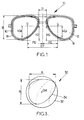
- Fig. 3 shows a representation of the contour of an ophthalmic lens, before and after edging.
- the thin line corresponds to the contour of the lens before edging; in a standard manner, the lens has a circular shape.
- the thick line corresponds to the contour of the template of the frame, which is also the contour of the lens after edging the lens. This edging of the lens followed or combined with a bevelling step allows the subsequent fitting of the lens in the spectacle frame.
- Fig. 3 shows the total width A of the template of the frame and the total height B of this template, i.e. the width and the height of the rectangle into which the cutout lens fits.
- the positioning of the lens in the frame consists in determining the desired position of the lens in the frame, using positioning data, for example notable points of the lens.
- the fitting cross of the lens the medium of micro-marks marked on the surface of the lens, or also the optical centre in the case of a single vision lens can be used.
- the fitting cross is marked by the cross referenced CM.
- Fig. 4 shows schematically an addition lens, before the latter has been edged around a contour C to the dimensions of a frame.
- the nasal and temporal sides of the lens respectively denoted N and T
- the meridian line LM the distance-vision and near-vision points
- VL and VP the distance-vision and near-vision points
- ⁇ an optical centre of the lens
- Fig. 5 shows a cross section of an edged and bevelled ophthalmic lens 100.
- Such ophthalmic lens presents a front face 102 and a rear face 104 and an external periphery 106.
- the rear face 104 is the face the closest to the eye of the wearer when the ophthalmic lens is fitted on the frame. Usually the rear face 104 is concave and the front face 102 is convex.
- the external periphery 106 is preceded during the edging and bevelling steps. As represented on Fig. 5 the external periphery presents fitting means, in this case a bevel 108. As discussed previously, the geometry of the bevel, in particular its position and shape, depends on the spectacle frame in which the ophthalmic lens is to be fitted.
- the external periphery of the lens can present a front face counter bevel 110 and a rear face counter bevel 112.
- the present invention relates to a method of calculating an optical system (OS) of an ophthalmic lens according to a given spectacle frame comprising the steps of:
- the final ophthalmic lens may be of any type of known lens, for example uncoloured lens or photochromic lens or solar lens.
- the geometrical data include at least contour and shape data.
- the contour data may be chosen from, but not limited to, the list comprising:
- the shape data may be chosen from, but not limited to, the list comprising:
- the geometrical data can be obtained by measuring a given spectacle frame using a measuring device well known in the art.
- the accuracy of the geometrical data is improved. Indeed, although the spectacle frames are produced based on a reference frame, small geometrical differences may exist between a given frame and the reference frame.
- the geometrical data can also be obtained from a spectacle frame data base.
- Advantageously such method is less time consuming.
- the geometrical data may also be obtained by a combination of measurements and use of a data base.
- the geometrical data may comprise, but is not limited to:
- the deformability data of the spectacle frame includes the deformability coefficient C d of the spectacle lens.
- the deformability coefficient C d may be preset for each frame materials or may be set according to esthetic criteria specified by the wearer.
- the deformability coefficient may be expressed in diopter, corresponding to the difference between the average tore of the spectacle frame when deformed and the average tore of the spectacle frame when not deformed, both expressed in refraction index of 1.53.
- the method according to the invention comprises a step of providing the surface curvature of a face of the ophthalmic lens, for example the front face.
- the wearer may wish to have a specific front base of the ophthalmic lens.
- the front base may be selected according to optical comfort criteria. Indeed it is generally more comfortable for the wearer to keep the same front base as his previous ophthalmic lenses.
- the front base may also be selected according to esthetic criteria.
- the wearer may wish to have the front base of the optical lens substantially equal to the front base of the spectacle frame.
- the curvature of the front face may also be selected according to optical criteria. Indeed for a given prescription they may be a preferred semi-finished lens.
- the surface curvature of the front face of the ophthalmic lens is provided and the semi-finished lens is selected according to the specific front base and to the wearer prescription.
- the wearer data comprise at least the wearer prescription data, and may also comprise elements chosen from, but not limited to, the list comprising:
- the "front curve tracing" is a criterion in which the bevel is formed so as to adjoin the front surface of the lens with the front surface of the spectacle frame.
- the "1:1" is a criterion in which the bevel is formed on the external edge of the ophthalmic lens at equidistance of the front and rear face of the ophthalmic lens.
- the "1:2" is a criterion in which the bevel is formed on the external edge of the ophthalmic lens so as to have the distance between the bevel and the front face of the lens equal to 1/2 of the distance between the bevel and the rear face of the lens.
- the prescription data may include little or no vision correction.
- the prescription may comprise no vision correction.
- the method according to the invention may comprise a step of providing customization data.
- the customization data may be chosen from, but not limited to, the list comprising:
- the optimization step of the method according to the invention may depend on the wearer data and the customization data.
- Positioning data may be used to optimize the optical system.
- the "positioning parameters" include at least the 3D or 2D position of a face of the lens according to the contour of a face of the spectacle frame.
- the positioning parameters may be chosen from, but not limited to, the list comprising:
- the optimization step is described in greater details when the optical system is calculated so as to position the front face of the ophthalmic lens according to the front face of the spectacle lens, with the "front curve tracing" esthetic criteria selected.
- the optimization step according to the invention comprises first the optimization of an optical surface of the ophthalmic lens different from the front surface of the ophthalmic lens.
- the optimization step also comprises the optimization of the edging parameters associate with the selected semi-finish lens and spectacle frame.
- edging parameters include at least the 2D or 3D position and shape of the bevel on the external profile of the ophthalmic lens.
- the edging parameters include at least a calculated bevel respecting:
- ⁇ C d C b C f - C d ⁇ when
- ⁇ C d ⁇ and C l - C f ⁇ 0 C b C f + C d ⁇ when
- the optimization step may include generating the edging parameters.
- the generated optical surface may be chosen from the list comprising:
- the generated optical surface should be adapted to the wearer prescription.
- the application WO 2007/017766 teaches a method when having a first surface of an optical system to calculate a second surface of the optical system according to a given prescription.
- the positioning parameter are generated according to positions criteria of the ophthalmic lens in the spectacle frame.
- the rear face of the ophthalmic lens and/or a diopter surface between the front an rear face of the ophthalmic lens are generated according not only the geometry of the front surface of the lens but also according to optical criteria, in particular to the wearer prescription.
- the optical system and the edging parameter of the ophthalmic lens are calculated so as to position the front face of the ophthalmic lens at a given distance from the front face of the spectacle frame.
- the given distance can be chosen by the wearer according to esthetic criteria, if not esthetic criterion is specified it can be considered that the "front curve tracing" criterion is applied.
- the "front curve tracing" criteria corresponds to the distance between the front face of the spectacle frame and the front face of the lens as small as possible.
- the positioning parameter of the ophthalmic lens are calculated so as to have the distance d between the Pf and Pl be smaller than 1 mm, preferably smaller than 0.5 mm, preferably smaller than 0.1 mm.
- Pf being the junction point between the front face of the spectacle frame and the internal profile of the spectacle frame.
- Pl being the junction point between the front face of the ophthalmic lens and the external profile of the ophthalmic lens.
- the distance d is calculated in a cross-section, therefore, the criterion should be continually applied for most of the cross sections of the spectacle frame, for example more than 50%, more than 70%, more than 80%, more than 90%, substantially 100%.
- the curvature of the front face of the spectacle frame is measured using a measuring device at the optician side.
- the front face of the semi-finished lens is selected by the lens manufacturer according to optical criteria, for example the wearer prescription.
- the bevel is calculated so as to have a curvature C b :
- C b C f when
- C b C f - C d ⁇ when
- C b C f + C d ⁇ when
- Fig 7 to 9 illustrate different ways of defining the difference between the front face of the ophthalmic lens and the front face of the optical lens.
- the difference between the front face of the ophthalmic lens and the front face of the optical lens may be express with the angle between Tf and Tl smaller than 15°, preferably smaller than 10°, preferably smaller than 5°.
- Tf being the tangent to the front face of the spectacle frame at the point Pf.
- Pf being the junction point between the front face of the spectacle frame and the internal profile of the spectacle frame.
- Tl being the tangent to the front face of the ophthalmic lens at the point Pl.
- Pl being the junction point between the front face of the ophthalmic lens and the external profile of the ophthalmic lens.
- the angle is calculated in a cross-section, therefore, the criteria should be continually applied for most of the cross sections of the spectacle frame, for example more than 50%, more than 70%, more than 80%, more than 90%, substantially 100%.
- Fig. 8 illustrates a situation where the distance d between Pf and Pl and the angle between Tf and Tl are close to zero.
- a configuration is continually applied to most of the cross-sections can be considered as having the front face of the ophthalmic lens as abutting the front face of the spectacle lens.
- the difference between the front face of the ophthalmic lens and the front face of the optical lens may be express with the average tore of the front face of the ophthalmic lens (having a refractory index of 1.53) differ of less than 0.5 Diopter, preferably of less than 0.25 Diopter, most preferably less 0.12 Diopter of the average tore of the front face of the spectacle frame.
- the average tore can be close to a sphere.
- Fig. 9 illustrates a situation where the average tore of the front face of the ophthalmic lens is sensibly equal to the average tore of the front face of the spectacle frame.
Landscapes
- Engineering & Computer Science (AREA)
- Physics & Mathematics (AREA)
- Geometry (AREA)
- General Physics & Mathematics (AREA)
- Theoretical Computer Science (AREA)
- Health & Medical Sciences (AREA)
- Computer Hardware Design (AREA)
- Ophthalmology & Optometry (AREA)
- General Engineering & Computer Science (AREA)
- Evolutionary Computation (AREA)
- Architecture (AREA)
- Computational Mathematics (AREA)
- Mathematical Analysis (AREA)
- Mathematical Optimization (AREA)
- Pure & Applied Mathematics (AREA)
- Civil Engineering (AREA)
- General Health & Medical Sciences (AREA)
- Structural Engineering (AREA)
- Optics & Photonics (AREA)
- Manufacturing & Machinery (AREA)
- Mechanical Engineering (AREA)
- Eyeglasses (AREA)
Priority Applications (7)
| Application Number | Priority Date | Filing Date | Title |
|---|---|---|---|
| ES07301761T ES2829678T3 (es) | 2007-12-28 | 2007-12-28 | Método para calcular un sistema óptico según una montura para gafas dada |
| EP07301761.8A EP2028533B1 (fr) | 2007-12-28 | 2007-12-28 | Procédé de calcul d'un système optique selon un cadre de lunettes donné |
| BRPI0821709-2A BRPI0821709B1 (pt) | 2007-12-28 | 2008-12-23 | Método para calcular um sistema óptico de acordo com uma dada armação de óculos, método de fabricação de lente oftálmica e método para pedir lente oftálmica |
| US12/811,095 US8308294B2 (en) | 2007-12-28 | 2008-12-23 | Method of calculating an optical system according to a given spectacle frame |
| MX2010007250A MX2010007250A (es) | 2007-12-28 | 2008-12-23 | Metodo para calcular un sistema optico de acuerdo con un armazon de anteojos dado. |
| CN200880127340.3A CN101946203B (zh) | 2007-12-28 | 2008-12-23 | 根据给定的眼镜架计算光学系统的方法 |
| PCT/EP2008/068264 WO2009065962A1 (fr) | 2007-12-28 | 2008-12-23 | Procédé de calcul d'un système optique selon une monture de lunettes donnée |
Applications Claiming Priority (1)
| Application Number | Priority Date | Filing Date | Title |
|---|---|---|---|
| EP07301761.8A EP2028533B1 (fr) | 2007-12-28 | 2007-12-28 | Procédé de calcul d'un système optique selon un cadre de lunettes donné |
Publications (2)
| Publication Number | Publication Date |
|---|---|
| EP2028533A1 true EP2028533A1 (fr) | 2009-02-25 |
| EP2028533B1 EP2028533B1 (fr) | 2020-09-23 |
Family
ID=39201560
Family Applications (1)
| Application Number | Title | Priority Date | Filing Date |
|---|---|---|---|
| EP07301761.8A Active EP2028533B1 (fr) | 2007-12-28 | 2007-12-28 | Procédé de calcul d'un système optique selon un cadre de lunettes donné |
Country Status (7)
| Country | Link |
|---|---|
| US (1) | US8308294B2 (fr) |
| EP (1) | EP2028533B1 (fr) |
| CN (1) | CN101946203B (fr) |
| BR (1) | BRPI0821709B1 (fr) |
| ES (1) | ES2829678T3 (fr) |
| MX (1) | MX2010007250A (fr) |
| WO (1) | WO2009065962A1 (fr) |
Cited By (5)
| Publication number | Priority date | Publication date | Assignee | Title |
|---|---|---|---|---|
| WO2014198894A1 (fr) * | 2013-06-13 | 2014-12-18 | Essilor International (Compagnie Generale D'optique) | Procédé de détermination de la surface d'une face d'un verre optique adapté à une monture de lunettes |
| WO2015150401A1 (fr) * | 2014-04-02 | 2015-10-08 | Essilor International (Compagnie Generale D'optique) | Procédé de calcul d'un système optique selon une monture de lunettes donnée |
| CN105264426A (zh) * | 2013-06-07 | 2016-01-20 | 埃西勒国际通用光学公司 | 用于确定光学设备的方法 |
| JP2020194186A (ja) * | 2013-04-29 | 2020-12-03 | エシロール エンテルナショナル | 眼科用レンズを提供するためのシステム |
| EP3789815A1 (fr) | 2019-09-03 | 2021-03-10 | Carl Zeiss Vision International GmbH | Procédé mis en uvre par ordinateur permettant d ajuster un verre de lunettes à une monture de lunettes |
Families Citing this family (10)
| Publication number | Priority date | Publication date | Assignee | Title |
|---|---|---|---|---|
| FR2962676B1 (fr) * | 2010-07-13 | 2012-08-03 | Essilor Int | Procede de detourage d'une lentille ophtalmique de lunettes comportant un film de revetement. |
| FR3010802B1 (fr) * | 2013-09-18 | 2015-10-16 | Luneau Technology Operations | Procede d'acquisition et de mesure de donnees geometriques d'un verre de demonstration adapte a une monture de lunettes |
| CN105916669B (zh) * | 2014-01-22 | 2017-12-22 | 埃西勒国际通用光学公司 | 用于对一组光学镜片坯件进行优化的方法 |
| US9699123B2 (en) | 2014-04-01 | 2017-07-04 | Ditto Technologies, Inc. | Methods, systems, and non-transitory machine-readable medium for incorporating a series of images resident on a user device into an existing web browser session |
| US10782541B2 (en) | 2015-11-23 | 2020-09-22 | Carl Zeiss Vision International Gmbh | Method for designing a lens shape and spectacle lens |
| BR112019009169A2 (pt) * | 2016-11-30 | 2019-07-16 | Essilor Int | método para fornecimento de um gráfico de seleção de lentes oftálmicas sem prescrição |
| US20180307058A1 (en) * | 2017-04-21 | 2018-10-25 | Carl Zeiss Vision International Gmbh | Computer implemented method of determining a base curve for a spectacle lens and method of manufacturing a spectacle lens |
| ES2753645T3 (es) * | 2017-07-06 | 2020-04-13 | Zeiss Carl Vision Int Gmbh | Procedimiento, dispositivo y programa informático para la adaptación virtual de una montura de gafas |
| JP7187799B2 (ja) * | 2018-03-30 | 2022-12-13 | 株式会社ニデック | 眼鏡レンズ周縁加工情報取得装置および眼鏡レンズ周縁加工情報取得プログラム |
| CN114578584A (zh) * | 2022-03-22 | 2022-06-03 | 天津市眼科医院视光中心有限公司 | 镜架与镜片的装配工艺 |
Citations (7)
| Publication number | Priority date | Publication date | Assignee | Title |
|---|---|---|---|---|
| EP0061918A1 (fr) * | 1981-03-27 | 1982-10-06 | Hoya Lens Corporation | Méthode de fabrication de lunettes |
| US4524419A (en) * | 1982-09-13 | 1985-06-18 | Intelab Medical Systems, Inc. | System for determining the optimal ground depth of an ophthalmic lens having a closed homeomorphic boundary |
| US4630906A (en) * | 1982-05-14 | 1986-12-23 | Carl-Zeiss-Stiftung | Blank for eyeglass lenses having ellipse-like edge curves and means and method for selecting |
| US5485399A (en) * | 1992-06-24 | 1996-01-16 | Hoya Corporation | Spectacle lens supply method |
| US20020176052A1 (en) * | 2000-10-27 | 2002-11-28 | Yasunori Ueno | Spectacle lens manufacturing method and spectacle lens supply system |
| US20070008488A1 (en) | 2003-08-19 | 2007-01-11 | Rodenstock Gmbh | Individual single vision spectacles |
| US20070242220A1 (en) * | 2006-03-01 | 2007-10-18 | Cyril Guilloux | Method for the Determination of a Progressive Ophthalmic Lens |
Family Cites Families (4)
| Publication number | Priority date | Publication date | Assignee | Title |
|---|---|---|---|---|
| JP4246422B2 (ja) * | 2001-09-11 | 2009-04-02 | セイコーオプティカルプロダクツ株式会社 | 累進屈折力眼鏡レンズの設計方法、および製造方法 |
| EP1752815A1 (fr) | 2005-08-11 | 2007-02-14 | Essilor International (Compagnie Generale D'optique) | Méthode de fabrication d'un système optique |
| EP2028529B1 (fr) * | 2007-12-28 | 2020-09-09 | Essilor International | Procédé de calcul d'un système optique selon une monture de lunettes donné |
| EP2028531B1 (fr) * | 2007-12-28 | 2016-05-04 | Essilor International (Compagnie Generale D'optique) | Procédé de sélection d'une lentille ophtalmique semi-finie selon un cadre de lunettes donné |
-
2007
- 2007-12-28 ES ES07301761T patent/ES2829678T3/es active Active
- 2007-12-28 EP EP07301761.8A patent/EP2028533B1/fr active Active
-
2008
- 2008-12-23 MX MX2010007250A patent/MX2010007250A/es active IP Right Grant
- 2008-12-23 CN CN200880127340.3A patent/CN101946203B/zh active Active
- 2008-12-23 BR BRPI0821709-2A patent/BRPI0821709B1/pt active IP Right Grant
- 2008-12-23 WO PCT/EP2008/068264 patent/WO2009065962A1/fr active Application Filing
- 2008-12-23 US US12/811,095 patent/US8308294B2/en active Active
Patent Citations (7)
| Publication number | Priority date | Publication date | Assignee | Title |
|---|---|---|---|---|
| EP0061918A1 (fr) * | 1981-03-27 | 1982-10-06 | Hoya Lens Corporation | Méthode de fabrication de lunettes |
| US4630906A (en) * | 1982-05-14 | 1986-12-23 | Carl-Zeiss-Stiftung | Blank for eyeglass lenses having ellipse-like edge curves and means and method for selecting |
| US4524419A (en) * | 1982-09-13 | 1985-06-18 | Intelab Medical Systems, Inc. | System for determining the optimal ground depth of an ophthalmic lens having a closed homeomorphic boundary |
| US5485399A (en) * | 1992-06-24 | 1996-01-16 | Hoya Corporation | Spectacle lens supply method |
| US20020176052A1 (en) * | 2000-10-27 | 2002-11-28 | Yasunori Ueno | Spectacle lens manufacturing method and spectacle lens supply system |
| US20070008488A1 (en) | 2003-08-19 | 2007-01-11 | Rodenstock Gmbh | Individual single vision spectacles |
| US20070242220A1 (en) * | 2006-03-01 | 2007-10-18 | Cyril Guilloux | Method for the Determination of a Progressive Ophthalmic Lens |
Cited By (13)
| Publication number | Priority date | Publication date | Assignee | Title |
|---|---|---|---|---|
| JP7243969B2 (ja) | 2013-04-29 | 2023-03-22 | エシロール エンテルナショナル | 眼科用レンズを提供するためのシステム |
| JP2020194186A (ja) * | 2013-04-29 | 2020-12-03 | エシロール エンテルナショナル | 眼科用レンズを提供するためのシステム |
| CN105264426A (zh) * | 2013-06-07 | 2016-01-20 | 埃西勒国际通用光学公司 | 用于确定光学设备的方法 |
| CN105264426B (zh) * | 2013-06-07 | 2017-06-09 | 埃西勒国际通用光学公司 | 用于确定光学设备的方法 |
| EP3800500A1 (fr) * | 2013-06-13 | 2021-04-07 | Essilor International | Procédé de détermination d'une surface d'une face d'une lentille optique adapté à une monture de lunettes |
| AU2014280084B2 (en) * | 2013-06-13 | 2018-08-16 | Essilor International | Method for determining a surface of a face of an optical lens adapted to a spectacle frame |
| US10345618B1 (en) | 2013-06-13 | 2019-07-09 | Essilor International | Method for determining a surface of an optical lens adapted to a spectacle frame |
| WO2014198894A1 (fr) * | 2013-06-13 | 2014-12-18 | Essilor International (Compagnie Generale D'optique) | Procédé de détermination de la surface d'une face d'un verre optique adapté à une monture de lunettes |
| US10509235B2 (en) | 2014-04-02 | 2019-12-17 | Essilor International | Method of calculating optical characteristics of an optical system according to a given spectacle frame |
| WO2015150401A1 (fr) * | 2014-04-02 | 2015-10-08 | Essilor International (Compagnie Generale D'optique) | Procédé de calcul d'un système optique selon une monture de lunettes donnée |
| WO2021043696A1 (fr) | 2019-09-03 | 2021-03-11 | Carl Zeiss Vision International Gmbh | Procédé mis en œuvre par ordinateur pour adapter un verre de lunettes à une monture de lunettes |
| EP3789815A1 (fr) | 2019-09-03 | 2021-03-10 | Carl Zeiss Vision International GmbH | Procédé mis en uvre par ordinateur permettant d ajuster un verre de lunettes à une monture de lunettes |
| US11693258B2 (en) | 2019-09-03 | 2023-07-04 | Carl Zeiss Vision International Gmbh | Computer-implemented method for fitting a spectacle lens to a spectacle frame |
Also Published As
| Publication number | Publication date |
|---|---|
| BRPI0821709B1 (pt) | 2019-04-24 |
| ES2829678T3 (es) | 2021-06-01 |
| US20100290003A1 (en) | 2010-11-18 |
| MX2010007250A (es) | 2010-11-09 |
| EP2028533B1 (fr) | 2020-09-23 |
| BRPI0821709A2 (pt) | 2015-06-16 |
| WO2009065962A1 (fr) | 2009-05-28 |
| CN101946203A (zh) | 2011-01-12 |
| US8308294B2 (en) | 2012-11-13 |
| BRPI0821709A8 (pt) | 2018-08-14 |
| CN101946203B (zh) | 2014-04-09 |
Similar Documents
| Publication | Publication Date | Title |
|---|---|---|
| EP2028531B1 (fr) | Procédé de sélection d'une lentille ophtalmique semi-finie selon un cadre de lunettes donné | |
| EP2028533B1 (fr) | Procédé de calcul d'un système optique selon un cadre de lunettes donné | |
| EP2028529B1 (fr) | Procédé de calcul d'un système optique selon une monture de lunettes donné | |
| EP2028527B1 (fr) | Procédé de sélection de base d'un verre pour lentille ophtalmique et procédé associé de fabrication de verres de lunettes | |
| EP2028532B1 (fr) | Procédé pour déterminer la forme du biseau d'une lentille ophtalmique | |
| CA2710633C (fr) | Procede de modification des donnees de forme de monture de lunettes | |
| US10345618B1 (en) | Method for determining a surface of an optical lens adapted to a spectacle frame | |
| EP3699675B1 (fr) | Procédé mis en oeuvre par ordinateur permettant de déterminer une courbe de base d'un verre de lunettes et procédé de fabrication d'un verre de lunettes |
Legal Events
| Date | Code | Title | Description |
|---|---|---|---|
| PUAI | Public reference made under article 153(3) epc to a published international application that has entered the european phase |
Free format text: ORIGINAL CODE: 0009012 |
|
| AK | Designated contracting states |
Kind code of ref document: A1 Designated state(s): AT BE BG CH CY CZ DE DK EE ES FI FR GB GR HU IE IS IT LI LT LU LV MC MT NL PL PT RO SE SI SK TR |
|
| AX | Request for extension of the european patent |
Extension state: AL BA HR MK RS |
|
| 17P | Request for examination filed |
Effective date: 20090211 |
|
| 17Q | First examination report despatched |
Effective date: 20090402 |
|
| AKX | Designation fees paid |
Designated state(s): AT BE BG CH CY CZ DE DK EE ES FI FR GB GR HU IE IS IT LI LT LU LV MC MT NL PL PT RO SE SI SK TR |
|
| RAP1 | Party data changed (applicant data changed or rights of an application transferred) |
Owner name: ESSILOR INTERNATIONAL |
|
| STAA | Information on the status of an ep patent application or granted ep patent |
Free format text: STATUS: EXAMINATION IS IN PROGRESS |
|
| REG | Reference to a national code |
Ref country code: DE Ref legal event code: R079 Ref document number: 602007060653 Country of ref document: DE Free format text: PREVIOUS MAIN CLASS: G02C0013000000 Ipc: G02C0007020000 |
|
| RIC1 | Information provided on ipc code assigned before grant |
Ipc: G06F 30/13 20200101ALI20200514BHEP Ipc: B29D 11/00 20060101ALI20200514BHEP Ipc: G02C 7/02 20060101AFI20200514BHEP Ipc: G06F 30/20 20200101ALI20200514BHEP |
|
| GRAP | Despatch of communication of intention to grant a patent |
Free format text: ORIGINAL CODE: EPIDOSNIGR1 |
|
| STAA | Information on the status of an ep patent application or granted ep patent |
Free format text: STATUS: GRANT OF PATENT IS INTENDED |
|
| INTG | Intention to grant announced |
Effective date: 20200715 |
|
| GRAS | Grant fee paid |
Free format text: ORIGINAL CODE: EPIDOSNIGR3 |
|
| GRAA | (expected) grant |
Free format text: ORIGINAL CODE: 0009210 |
|
| STAA | Information on the status of an ep patent application or granted ep patent |
Free format text: STATUS: THE PATENT HAS BEEN GRANTED |
|
| AK | Designated contracting states |
Kind code of ref document: B1 Designated state(s): AT BE BG CH CY CZ DE DK EE ES FI FR GB GR HU IE IS IT LI LT LU LV MC MT NL PL PT RO SE SI SK TR |
|
| REG | Reference to a national code |
Ref country code: GB Ref legal event code: FG4D |
|
| REG | Reference to a national code |
Ref country code: CH Ref legal event code: EP |
|
| REG | Reference to a national code |
Ref country code: DE Ref legal event code: R096 Ref document number: 602007060653 Country of ref document: DE |
|
| REG | Reference to a national code |
Ref country code: IE Ref legal event code: FG4D |
|
| REG | Reference to a national code |
Ref country code: AT Ref legal event code: REF Ref document number: 1316988 Country of ref document: AT Kind code of ref document: T Effective date: 20201015 |
|
| PG25 | Lapsed in a contracting state [announced via postgrant information from national office to epo] |
Ref country code: FI Free format text: LAPSE BECAUSE OF FAILURE TO SUBMIT A TRANSLATION OF THE DESCRIPTION OR TO PAY THE FEE WITHIN THE PRESCRIBED TIME-LIMIT Effective date: 20200923 Ref country code: BG Free format text: LAPSE BECAUSE OF FAILURE TO SUBMIT A TRANSLATION OF THE DESCRIPTION OR TO PAY THE FEE WITHIN THE PRESCRIBED TIME-LIMIT Effective date: 20201223 Ref country code: SE Free format text: LAPSE BECAUSE OF FAILURE TO SUBMIT A TRANSLATION OF THE DESCRIPTION OR TO PAY THE FEE WITHIN THE PRESCRIBED TIME-LIMIT Effective date: 20200923 Ref country code: GR Free format text: LAPSE BECAUSE OF FAILURE TO SUBMIT A TRANSLATION OF THE DESCRIPTION OR TO PAY THE FEE WITHIN THE PRESCRIBED TIME-LIMIT Effective date: 20201224 |
|
| REG | Reference to a national code |
Ref country code: AT Ref legal event code: MK05 Ref document number: 1316988 Country of ref document: AT Kind code of ref document: T Effective date: 20200923 |
|
| PG25 | Lapsed in a contracting state [announced via postgrant information from national office to epo] |
Ref country code: LV Free format text: LAPSE BECAUSE OF FAILURE TO SUBMIT A TRANSLATION OF THE DESCRIPTION OR TO PAY THE FEE WITHIN THE PRESCRIBED TIME-LIMIT Effective date: 20200923 |
|
| REG | Reference to a national code |
Ref country code: NL Ref legal event code: MP Effective date: 20200923 |
|
| REG | Reference to a national code |
Ref country code: LT Ref legal event code: MG4D |
|
| PG25 | Lapsed in a contracting state [announced via postgrant information from national office to epo] |
Ref country code: NL Free format text: LAPSE BECAUSE OF FAILURE TO SUBMIT A TRANSLATION OF THE DESCRIPTION OR TO PAY THE FEE WITHIN THE PRESCRIBED TIME-LIMIT Effective date: 20200923 Ref country code: PT Free format text: LAPSE BECAUSE OF FAILURE TO SUBMIT A TRANSLATION OF THE DESCRIPTION OR TO PAY THE FEE WITHIN THE PRESCRIBED TIME-LIMIT Effective date: 20210125 Ref country code: LT Free format text: LAPSE BECAUSE OF FAILURE TO SUBMIT A TRANSLATION OF THE DESCRIPTION OR TO PAY THE FEE WITHIN THE PRESCRIBED TIME-LIMIT Effective date: 20200923 Ref country code: RO Free format text: LAPSE BECAUSE OF FAILURE TO SUBMIT A TRANSLATION OF THE DESCRIPTION OR TO PAY THE FEE WITHIN THE PRESCRIBED TIME-LIMIT Effective date: 20200923 Ref country code: EE Free format text: LAPSE BECAUSE OF FAILURE TO SUBMIT A TRANSLATION OF THE DESCRIPTION OR TO PAY THE FEE WITHIN THE PRESCRIBED TIME-LIMIT Effective date: 20200923 Ref country code: CZ Free format text: LAPSE BECAUSE OF FAILURE TO SUBMIT A TRANSLATION OF THE DESCRIPTION OR TO PAY THE FEE WITHIN THE PRESCRIBED TIME-LIMIT Effective date: 20200923 |
|
| PG25 | Lapsed in a contracting state [announced via postgrant information from national office to epo] |
Ref country code: PL Free format text: LAPSE BECAUSE OF FAILURE TO SUBMIT A TRANSLATION OF THE DESCRIPTION OR TO PAY THE FEE WITHIN THE PRESCRIBED TIME-LIMIT Effective date: 20200923 Ref country code: AT Free format text: LAPSE BECAUSE OF FAILURE TO SUBMIT A TRANSLATION OF THE DESCRIPTION OR TO PAY THE FEE WITHIN THE PRESCRIBED TIME-LIMIT Effective date: 20200923 Ref country code: IS Free format text: LAPSE BECAUSE OF FAILURE TO SUBMIT A TRANSLATION OF THE DESCRIPTION OR TO PAY THE FEE WITHIN THE PRESCRIBED TIME-LIMIT Effective date: 20210123 |
|
| REG | Reference to a national code |
Ref country code: ES Ref legal event code: FG2A Ref document number: 2829678 Country of ref document: ES Kind code of ref document: T3 Effective date: 20210601 |
|
| REG | Reference to a national code |
Ref country code: DE Ref legal event code: R097 Ref document number: 602007060653 Country of ref document: DE |
|
| PG25 | Lapsed in a contracting state [announced via postgrant information from national office to epo] |
Ref country code: SK Free format text: LAPSE BECAUSE OF FAILURE TO SUBMIT A TRANSLATION OF THE DESCRIPTION OR TO PAY THE FEE WITHIN THE PRESCRIBED TIME-LIMIT Effective date: 20200923 |
|
| PLBE | No opposition filed within time limit |
Free format text: ORIGINAL CODE: 0009261 |
|
| STAA | Information on the status of an ep patent application or granted ep patent |
Free format text: STATUS: NO OPPOSITION FILED WITHIN TIME LIMIT |
|
| PG25 | Lapsed in a contracting state [announced via postgrant information from national office to epo] |
Ref country code: MC Free format text: LAPSE BECAUSE OF FAILURE TO SUBMIT A TRANSLATION OF THE DESCRIPTION OR TO PAY THE FEE WITHIN THE PRESCRIBED TIME-LIMIT Effective date: 20200923 Ref country code: DK Free format text: LAPSE BECAUSE OF FAILURE TO SUBMIT A TRANSLATION OF THE DESCRIPTION OR TO PAY THE FEE WITHIN THE PRESCRIBED TIME-LIMIT Effective date: 20200923 Ref country code: SI Free format text: LAPSE BECAUSE OF FAILURE TO SUBMIT A TRANSLATION OF THE DESCRIPTION OR TO PAY THE FEE WITHIN THE PRESCRIBED TIME-LIMIT Effective date: 20200923 |
|
| 26N | No opposition filed |
Effective date: 20210624 |
|
| REG | Reference to a national code |
Ref country code: BE Ref legal event code: MM Effective date: 20201231 |
|
| PG25 | Lapsed in a contracting state [announced via postgrant information from national office to epo] |
Ref country code: LU Free format text: LAPSE BECAUSE OF NON-PAYMENT OF DUE FEES Effective date: 20201228 Ref country code: IE Free format text: LAPSE BECAUSE OF NON-PAYMENT OF DUE FEES Effective date: 20201228 |
|
| PG25 | Lapsed in a contracting state [announced via postgrant information from national office to epo] |
Ref country code: TR Free format text: LAPSE BECAUSE OF FAILURE TO SUBMIT A TRANSLATION OF THE DESCRIPTION OR TO PAY THE FEE WITHIN THE PRESCRIBED TIME-LIMIT Effective date: 20200923 Ref country code: MT Free format text: LAPSE BECAUSE OF FAILURE TO SUBMIT A TRANSLATION OF THE DESCRIPTION OR TO PAY THE FEE WITHIN THE PRESCRIBED TIME-LIMIT Effective date: 20200923 Ref country code: CY Free format text: LAPSE BECAUSE OF FAILURE TO SUBMIT A TRANSLATION OF THE DESCRIPTION OR TO PAY THE FEE WITHIN THE PRESCRIBED TIME-LIMIT Effective date: 20200923 |
|
| PG25 | Lapsed in a contracting state [announced via postgrant information from national office to epo] |
Ref country code: BE Free format text: LAPSE BECAUSE OF NON-PAYMENT OF DUE FEES Effective date: 20201231 |
|
| P01 | Opt-out of the competence of the unified patent court (upc) registered |
Effective date: 20230525 |
|
| PGFP | Annual fee paid to national office [announced via postgrant information from national office to epo] |
Ref country code: GB Payment date: 20231227 Year of fee payment: 17 |
|
| PGFP | Annual fee paid to national office [announced via postgrant information from national office to epo] |
Ref country code: IT Payment date: 20231220 Year of fee payment: 17 Ref country code: FR Payment date: 20231227 Year of fee payment: 17 |
|
| PGFP | Annual fee paid to national office [announced via postgrant information from national office to epo] |
Ref country code: ES Payment date: 20240102 Year of fee payment: 17 |
|
| PGFP | Annual fee paid to national office [announced via postgrant information from national office to epo] |
Ref country code: DE Payment date: 20231229 Year of fee payment: 17 Ref country code: CH Payment date: 20240101 Year of fee payment: 17 |