EP2028341A1 - A device and method for analyzing light chemical compounds - Google Patents
A device and method for analyzing light chemical compounds Download PDFInfo
- Publication number
- EP2028341A1 EP2028341A1 EP07291037A EP07291037A EP2028341A1 EP 2028341 A1 EP2028341 A1 EP 2028341A1 EP 07291037 A EP07291037 A EP 07291037A EP 07291037 A EP07291037 A EP 07291037A EP 2028341 A1 EP2028341 A1 EP 2028341A1
- Authority
- EP
- European Patent Office
- Prior art keywords
- sensor
- fluid sample
- analyzing
- chamber
- high pressure
- Prior art date
- Legal status (The legal status is an assumption and is not a legal conclusion. Google has not performed a legal analysis and makes no representation as to the accuracy of the status listed.)
- Granted
Links
- 150000001875 compounds Chemical class 0.000 title claims abstract description 44
- 238000000034 method Methods 0.000 title claims description 18
- 239000012530 fluid Substances 0.000 claims abstract description 85
- 238000005259 measurement Methods 0.000 claims abstract description 26
- 238000010408 sweeping Methods 0.000 claims abstract description 6
- 230000003287 optical effect Effects 0.000 claims description 31
- 238000005070 sampling Methods 0.000 claims description 17
- 238000010438 heat treatment Methods 0.000 claims description 10
- 239000007788 liquid Substances 0.000 claims description 9
- 239000007791 liquid phase Substances 0.000 claims description 7
- 238000004847 absorption spectroscopy Methods 0.000 claims description 6
- 238000002235 transmission spectroscopy Methods 0.000 claims description 4
- 238000004817 gas chromatography Methods 0.000 claims description 3
- 230000015572 biosynthetic process Effects 0.000 description 12
- 238000005755 formation reaction Methods 0.000 description 12
- 239000004215 Carbon black (E152) Substances 0.000 description 8
- 229930195733 hydrocarbon Natural products 0.000 description 8
- 150000002430 hydrocarbons Chemical class 0.000 description 8
- 238000010586 diagram Methods 0.000 description 6
- 239000000203 mixture Substances 0.000 description 6
- 238000005553 drilling Methods 0.000 description 5
- 238000004458 analytical method Methods 0.000 description 4
- 239000007789 gas Substances 0.000 description 4
- 238000012545 processing Methods 0.000 description 4
- 238000002955 isolation Methods 0.000 description 3
- VYPSYNLAJGMNEJ-UHFFFAOYSA-N Silicium dioxide Chemical compound O=[Si]=O VYPSYNLAJGMNEJ-UHFFFAOYSA-N 0.000 description 2
- 238000004891 communication Methods 0.000 description 2
- 230000006870 function Effects 0.000 description 2
- 238000002347 injection Methods 0.000 description 2
- 239000007924 injection Substances 0.000 description 2
- 239000013307 optical fiber Substances 0.000 description 2
- 230000000149 penetrating effect Effects 0.000 description 2
- 239000000126 substance Substances 0.000 description 2
- 238000012546 transfer Methods 0.000 description 2
- 238000011144 upstream manufacturing Methods 0.000 description 2
- 229910052724 xenon Inorganic materials 0.000 description 2
- FHNFHKCVQCLJFQ-UHFFFAOYSA-N xenon atom Chemical compound [Xe] FHNFHKCVQCLJFQ-UHFFFAOYSA-N 0.000 description 2
- 241000951490 Hylocharis chrysura Species 0.000 description 1
- 238000010521 absorption reaction Methods 0.000 description 1
- 238000000862 absorption spectrum Methods 0.000 description 1
- 150000001335 aliphatic alkanes Chemical class 0.000 description 1
- 230000005540 biological transmission Effects 0.000 description 1
- 239000000919 ceramic Substances 0.000 description 1
- 238000010276 construction Methods 0.000 description 1
- 238000001514 detection method Methods 0.000 description 1
- 230000000694 effects Effects 0.000 description 1
- 239000007792 gaseous phase Substances 0.000 description 1
- 238000011065 in-situ storage Methods 0.000 description 1
- 238000004519 manufacturing process Methods 0.000 description 1
- 239000000463 material Substances 0.000 description 1
- 239000002184 metal Substances 0.000 description 1
- 238000012986 modification Methods 0.000 description 1
- 230000004048 modification Effects 0.000 description 1
- 238000012544 monitoring process Methods 0.000 description 1
- 239000003921 oil Substances 0.000 description 1
- 239000012071 phase Substances 0.000 description 1
- 239000011148 porous material Substances 0.000 description 1
- 229910052704 radon Inorganic materials 0.000 description 1
- SYUHGPGVQRZVTB-UHFFFAOYSA-N radon atom Chemical compound [Rn] SYUHGPGVQRZVTB-UHFFFAOYSA-N 0.000 description 1
- 229910052594 sapphire Inorganic materials 0.000 description 1
- 239000010980 sapphire Substances 0.000 description 1
- 239000010865 sewage Substances 0.000 description 1
- 239000000377 silicon dioxide Substances 0.000 description 1
- 239000011343 solid material Substances 0.000 description 1
- 238000004611 spectroscopical analysis Methods 0.000 description 1
- 238000001228 spectrum Methods 0.000 description 1
- 238000000411 transmission spectrum Methods 0.000 description 1
- XLYOFNOQVPJJNP-UHFFFAOYSA-N water Substances O XLYOFNOQVPJJNP-UHFFFAOYSA-N 0.000 description 1
Images

Classifications
-
- E—FIXED CONSTRUCTIONS
- E21—EARTH DRILLING; MINING
- E21B—EARTH DRILLING, e.g. DEEP DRILLING; OBTAINING OIL, GAS, WATER, SOLUBLE OR MELTABLE MATERIALS OR A SLURRY OF MINERALS FROM WELLS
- E21B49/00—Testing the nature of borehole walls; Formation testing; Methods or apparatus for obtaining samples of soil or well fluids, specially adapted to earth drilling or wells
- E21B49/08—Obtaining fluid samples or testing fluids, in boreholes or wells
-
- G—PHYSICS
- G01—MEASURING; TESTING
- G01N—INVESTIGATING OR ANALYSING MATERIALS BY DETERMINING THEIR CHEMICAL OR PHYSICAL PROPERTIES
- G01N33/00—Investigating or analysing materials by specific methods not covered by groups G01N1/00 - G01N31/00
- G01N33/26—Oils; viscous liquids; paints; inks
- G01N33/28—Oils, i.e. hydrocarbon liquids
- G01N33/2835—Oils, i.e. hydrocarbon liquids specific substances contained in the oil or fuel
- G01N33/287—Sulfur content
-
- G—PHYSICS
- G01—MEASURING; TESTING
- G01N—INVESTIGATING OR ANALYSING MATERIALS BY DETERMINING THEIR CHEMICAL OR PHYSICAL PROPERTIES
- G01N21/00—Investigating or analysing materials by the use of optical means, i.e. using sub-millimetre waves, infrared, visible or ultraviolet light
- G01N21/17—Systems in which incident light is modified in accordance with the properties of the material investigated
- G01N21/25—Colour; Spectral properties, i.e. comparison of effect of material on the light at two or more different wavelengths or wavelength bands
- G01N21/31—Investigating relative effect of material at wavelengths characteristic of specific elements or molecules, e.g. atomic absorption spectrometry
- G01N21/35—Investigating relative effect of material at wavelengths characteristic of specific elements or molecules, e.g. atomic absorption spectrometry using infrared light
- G01N21/3504—Investigating relative effect of material at wavelengths characteristic of specific elements or molecules, e.g. atomic absorption spectrometry using infrared light for analysing gases, e.g. multi-gas analysis
Definitions
- the invention relates to a device and a method used for analyzing light chemical compounds of fluids flowing in a borehole penetrating geological formations, or fluids present in the geological formations.
- the invention finds a particular application in the oilfield industry.
- the document GB 2 344 365 describes a sampling tool for trapping and concentrating volatile component of a well effluent on a solid material for further analysis.
- Such a technique and sampling tool has the drawbacks that the collected samples must be sent at the surface for analysis in specialized laboratories. Thus, the measurements are made off-line. This is most of the time incompatible with the current trend of construction of hydrocarbon production; processing and transportation facilities where it is desirable to quickly know whether corrosive compounds (e.g. H 2 S) are contained within the formation fluids in order to select the appropriate metal used for the various pipes.
- corrosive compounds e.g. H 2 S
- the documents US 7,025,138 and US 2006/0243603 describe apparatuses for in-situ monitoring of the corrosive compounds (e.g. H 2 S) contained within the downhole formation fluids.
- Such techniques and apparatuses have the drawbacks that the sample pressure is imposed by the well pressure.
- the sample phase is not controlled and may be multiphase, e.g. a mixture of liquid water, oil, and gas.
- the presence of liquid phase in the sample limits the accuracy of measurements on light compounds. Even for pure gas effluents, the measurement dynamic range (ratio between the highest and lowest concentrations that can be measured) is limited.
- the invention relates to an analyzing device to analyze light chemical compounds comprising:
- the analyzing sensor may further comprises a temperature regulator, operations of which being commanded by the controller.
- the injector may comprise a sliding valve fitted in a body, the sliding valve comprising a sampling chamber, at least one seal and an output port, the body being coupled to the flow-line and comprising a bypass groove.
- the sampling chamber may comprise walls that are textured such as to enhance the trapping of liquid in the sampling chamber.
- the device may further comprise a first check valve between the high pressure chamber and the sensor to prevent the fluid sample from uncontrolled exit of the high pressure chamber.
- the device may further comprise a second check valve between the high pressure chamber and the flow-line to prevent the fluid of the flow-line to enter the high pressure chamber through an output port.
- the device may further comprise a filter between the low pressure chamber and the analyzing sensor to trap at least a portion of a liquid phase contained in the fluid sample.
- the sensor may be an optical absorption/transmission spectroscopy sensor comprising a housing defining an optical cell, an inlet port, an output port, and an optical path between a light source and a detector coupled to the optical cell by respective wave guides.
- the sensor may be a gas chromatography sensor.
- the control sensors may comprise a pressure sensor and a temperature sensor.
- the temperature regulator may be a heating coil to adjust the temperature within the analyzing sensor at an optimal temperature value.
- the high pressure piston has a smaller cross section than the low pressure piston.
- the invention relates to a method to analyze light chemical compounds comprising the steps of:
- the method further comprises the step of heating the fluid sample in the sensor chamber until the temperature measured in the chamber of the sensor is optimal.
- the pressure may be adjusted from a low value to a high value while measuring at least one characteristic related to at least one compounds of the fluid sample such as a range of concentration of the compound is swept, the optimal pressure corresponding to a light compound concentration associated with the lowest measurement error.
- the optimal temperature may correspond to substantially the flow-line temperature.
- the invention enables depressurizing the sample so that light compounds of the fluid sample become gaseous and preventing the liquid phase from reaching the sensor. Further, the invention enables controlling the sample pressure and temperature when the measurements are taken.
- the capacity of the analyzing device to provide accurate measurements related to light chemical compounds is not limited, and independent on the well pressure.
- the invention is adapted to perform downhole analysis of light chemical compounds contained in pressurized effluents of hydrocarbon well. Furthermore, once analyzed, the sample is discarded downhole and the sensor chamber is automatically "regenerated" for further measurements.
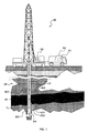
- FIG. 1 schematically shows a typical onshore hydrocarbon well location and surface equipments SE above hydrocarbon geological formations GF after drilling operations have been carried out.
- the wellbore is a borehole BH filled with a fluid mixture MD.
- the fluid mixture MD is typically a mixture of drilling fluid and drilling mud.
- the surface equipments SE comprise an oil rig and a surface unit SU for deploying a logging tool TL in the well-bore.
- the surface unit may be a vehicle coupled to the logging tool by a line LN.
- the surface unit comprises an appropriate device DD for determining the depth position of the logging tool relatively to the surface level.
- the logging tool TL comprises an analyzing device AD1 that performs chemical analysis of the fluid contained within the geological formation GF or flowing into the borehole BH.
- the logging tool may comprise various other sensors and may provide various measurement data related to the hydrocarbon geological formation GF and/or the fluid mixture DM (e.g. conductivity, resistivity, etc). These measurement data are collected by the logging tool TL and may be transmitted to the surface unit SU by any known technique, or otherwise stored in the logging tool memory for subsequent processing when the memory is returned to the surface.
- the surface unit SU comprises appropriate electronic and software arrangements PA for processing, analyzing and storing the measurement data provided by the logging tool TL.
- the analyzing device AD2 may be positioned within the geological formation GF, for example in the selected zone SZ of the formation.
- the analyzing device AD3 may be positioned on the borehole wall.
- the logging apparatus of FIG. 1 can also be adapted into a logging-while-drilling tool by mounting the logging tool TL on a drill collar. More precisely, a typical logging-while-drilling tool is incorporated into a bottom-hole assembly attached to the end of a drill string with a drill bit attached at the extreme end thereof. Measurements can be made either when the drill string is stationary or rotating. The measurement data that are collected by the logging tool may be transmitted by means of the known mud pulse technique to the surface unit coupled to a mud pulse receiver.
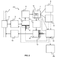
- FIG. 2 is a functional diagram illustrating the device for analyzing light chemical compounds of the invention.
- the device for analyzing light chemical compounds AD comprises an injector 3, a low pressure chamber 4 and piston 5, an analyzing sensor 7, a plurality of control sensors 8, 9, a temperature regulator 15, a first check valve 10, a high pressure chamber 11 and piston 12, a second check valve 13, and a controller 14.
- a fluid to be analyzed flows through a flow line 1.
- the flow line 1 schematically represents either the borehole BH or the vicinity of the analyzing device AD where a fluid is present.
- the fluid is sampled at an intake 2 of the injector 3.
- the injector 3 flashes the sample of fluid to pressure lower than the pressure of the fluid in the flow line 1.
- the intake pressure is the well pressure, e.g. typically from around 70 bars to around 700 bars.
- the sample is injected in the low pressure chamber 4.
- the sample injected in the low pressure chamber is around 0.1 ml under pressure.
- the pressure in the low pressure chamber is from around 0.2 bar to around 7 bar.
- the low pressure chamber 4 comprises the low pressure piston 5.
- the low pressure chamber volume is about 10 ml.
- the volume of the connecting tubes (not shown) between the different elements and the sensor, that are upstream the check valve 10, are smaller than the volume of the low pressure chamber 4. This enables a good efficiency of the fluid transfer from the low pressure chamber 4 to the high pressure chamber 11.
- the analyzing device AD may further comprise a filter 6 between the low pressure chamber 4 and the analyzing sensor 7.
- the filter 6 is a liquid filter that traps the remaining liquid phase from the sample.
- the liquid filter may be designed to maintain the liquid phase away from the sensor by trapping it. It may be made of a fritted inert material such as porous ceramic having a pore size of the order of 10 ⁇ m. Through viscosity effect, the liquid in the sample moves slowly in the filter while being bypassed by the gaseous phase of lower viscosity than the liquid phase.
- the analyzing sensor 7 is coupled to the plurality of control sensors 8, 9.
- the pressure and the temperature of the sample in the sensor 7 are monitored via a pressure sensor 8 and a temperature sensor 9, respectively.
- the low pressure piston 5 moves in order to adjust the pressure within the analyzing sensor 7 so that an optimal pressure is reached.
- the pressure during measurement is around 10 bar and is increased in order to reach 100 bar.
- the analyzing sensor 7 may also comprise a temperature regulator, for example a heating coil 15. The heating coil 15 heats the sensor in order to adjust the temperature within the analyzing sensor 7 so that an optimal temperature is reached.
- the low pressure piston 5 continues to move so as to reach a full extension course. As a consequence, the sample is pushed toward the high pressure chamber 11, through the first check valve 10.
- the high pressure chamber 11 comprises the high pressure piston 12.
- the high pressure chamber volume is about 1 ml.
- the volume of the connecting tubes between the different elements, that are upstream the high pressure chamber 11, are smaller than the volume of the high pressure chamber 11. This enables a good efficiency of the fluid transfer from the high pressure chamber 11 back to the flow line 1.
- the actuation of the low pressure 5 and high pressure 12 pistons may be hydraulic or electrical.
- the two pistons have different cross section to minimize the range of force which is required to actuate them.
- the high pressure piston 12 may have a smaller cross section than the low pressure piston 5.
- the controller 14 is coupled to and receives measurements from the sensor 7, the pressure sensor 8 and the temperature sensor 9.
- the controller 14 is coupled to and commands the operations of the injector 3, the low pressure piston 5, the heating coil 15 and the high pressure piston 12.
- the controller 14 may be further coupled to the processing arrangement PA of the surface equipment or to a memory (not shown) for real-time or subsequent interpretation of the measurements.
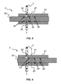
- FIGS. 3 and 4 are cross-section views showing in details the injector 3 of FIGS. 2 and illustrating the injector 3 operation.
- the injector comprises a sliding valve 20, a body 21, a bypass groove 22, a sampling chamber 23, various seals 24, 25, and 26, and an output port 27.
- the sliding valve 20 is fitted into the body 21.
- the intake and injection are performed by the movement of the sliding valve 20 relatively to the body 21.
- the sliding valve 20 moves between two positions.
- a volume of fluid forming a sample volume is defined by the sampling chamber 23.
- the sampling chamber is defined by an annular groove in the sliding valve 20.
- the sampling chamber 23 is always in contact with the effluents flowing in the flow line 1.
- the volume of fluid present in the sampling chamber 23 is continuously renewed by the flow.
- the sample volume is isolated from the flow line 1 and put in communication with the low pressure chamber 4 via the output port 27.
- the bypass groove 22 bypasses the sliding valve 20 and enables the flow line continuing flowing through the injector 3.
- the sliding valve 20 reaches the second position, the sample volume is flashed towards the low pressure chamber 4.
- the three seals 24, 25 and 26 are O-ring seals.
- Two O-ring seals are positioned on each side of the annular sampling chamber 23.
- the third O-ring seal is positioned such that, in the second position, the output port 27 is encompassed on each side by such an O-ring seal. They insure a good isolation between, on the one side, the flow line 1 and the bypass groove 22, and, on the other side, the output port 27. With this configuration, a good isolation is maintained even when a high pressure differential exists between the flow line 1 and the low pressure chamber 4.
- the wall of the annular sampling chamber 23 of the sliding valve 20 may be textured such as to enhance the trapping of liquid in the sampling chamber 23.
- the textured wall maximizes the surface to which the flowing fluid is exposed. The capillary forces retain the liquid on the wall surface of the sampling chamber 23 while the gas is expelled (due to the flashing process) toward the low pressure chamber 4.
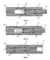
- FIGS. 5, 6 and 7 are cross-section views showing in details the check valve 10 of FIG. 2 and illustrating the check valve operation.
- the first check valve 10 has the function of preventing the liquid which has entered the high pressure chamber 11 from exiting it, when the high pressure piston 12 is actuated.
- the check valve may be implemented on the high pressure piston which acts as a sliding valve.
- the check valve comprises a body 41, the high pressure piston 12, an inlet port 42, an outlet port 45 and two seals 43 and 44.
- the high pressure piston 12 may move continuously in the high pressure chamber 11 from a fully retracted position depicted in FIG. 5 , followed by a middle position depicted in FIG. 6 , to a fully extended position depicted in FIG. 7 .
- the sample is compressed and pushed from the high pressure chamber 11 toward the flow line 1 via the outlet port 45.
- the inlet port 42 is in communication with the high pressure chamber 11.
- the high pressure piston 12 starts moving as soon as the sample has been transferred from the chamber of the sensor 7 into the high pressure chamber 11. Then, the chamber inlet port 42 is getting closed ( FIG. 6 ), thus, preventing the sample fluid from returning back in the sensor 7 through the inlet port 42.
- the high pressure piston 12 is in the fully extended position ( FIG. 7 )
- the sample is flushed out of the analyzing device AD into the flow line 1.
- the two seals 43 and 44 are O-ring seals.
- the two O-ring seals are positioned such that, in the fully extended position ( FIG. 7 ), the inlet port 42 is encompassed on each side by such an O-ring seal. With this configuration, a good isolation is maintained even when a high pressure differential exists between the flow line 1 and the chamber of the sensor 7.
- the second check valve 13 has the function of preventing the fluid of the flow line 1 to enter the high pressure chamber 11 through the output port of the device for analyzing light chemical compounds AD.
- the second check valve 13 is for example a ball check valve that is known in the art.
- the sensor is a sensor that is able to measure light or volatile chemical compounds in the gas portion of the sample.
- Typical light chemical compounds that may be measured are H 2 S, CO 2 , Hg, Radon, low weight alkane, etc.
- Typical operating principle of the sensor may be based on gas chromatography, optical absorption/transmission spectroscopy, etc...
- FIG. 8 depicts a functional diagram illustrating an embodiment of a sensor 7 under the form of an optical absorption/transmission spectroscopy sensor.
- the absorption/transmission spectrometer comprises a housing defining an optical cell 31, an inlet port 32, an output port 36, a light source 37, a detector 34, and wave guides 35 and 38.
- the sensor 7 is coupled to a pressure sensor 8 and a temperature sensor 9.
- the sensor 7 may further comprise a heating coil 15.
- the housing defines an optical cell 31 in which the sample may be analyzed.
- the sample flows from the low pressure chamber 4 into the optical cell through the inlet port 32, and flows out of the optical cell through the output port 36.
- the light source 37 can be any kind of electromagnetic wave emitter operating at wavelengths from infra-red to ultra-violet.
- the light source 37 may be a light emitting diode, or an incandescent lamp, or a Xenon lamp, etc...
- the light source 37 is coupled to the optical cell though a first waveguide 35.
- the detector 34 is any detector capable of providing dispersive or non dispersive spectroscopy measurement.
- the detector 34 is coupled to the optical cell though a second waveguide 38.
- the waveguides 35 and 38 can be made out of sapphire rod, or silica based optical fibers. They can also be made of a combination of optical fibers and chemically resistant windows provided in the walls of the optical cell, e.g. sapphire windows.
- the electromagnetic waves travel through the optical cell from the light source to the detector via a straight optical path 33.
- the sample of fluid flows through the optical path 33 from the inlet port 32 to the output port 36.
- the electromagnetic waves traveling through the optical cell are modified by the compounds present in the sample of fluid. The detection of these modifications (absorption/transmission spectrum) enables detecting the compounds and their respective quantities in the sample of fluid.
- the optical sensor may also comprise appropriate filters (not shown).
- the pressure sensor 8 measures the pressure of the sample in the optical cell 31. It allows controlling the sample pressure in the sensor via the low pressure piston 5.
- the dead volume associated with the pressure sensor 8 is smaller than the total volume of the low pressure chamber 11.
- the temperature sensor 9 measures the temperature of the sample in the optical cell 31. It allows controlling the sample temperature in the sensor via the heating coil 15.
- a sensor 7 for H 2 S measurement under the form of an optical absorption spectroscopy sensor may have the following characteristics.
- the optical cell optical path length may be of the order of 2 cm.
- the optical path cross section may be of the order of 500 ⁇ m.
- the light source may be a pulsed Xenon light source, providing an electromagnetic wave having a spectrum with ray around 200 nm.
- the detector operates in the 200 nm region.
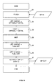
- FIG. 9 is a diagram illustrating the sequence of steps of the method for analyzing light chemical compounds of the invention. The sequence of operations is controlled by the controller 14.
- a first step S1 the injector 3 flashes a sample of fluid SP in the low pressure chamber 4.
- the sample of fluid SP is taken from the flow-line 1.
- the sample of fluid is depressurized so that light compounds of the sample become gaseous.
- a second step S2 the low pressure piston 5 moves until the pressure measured in the chamber of the sensor 7 is optimal.
- the heating coil 15 may heat the fluid sample in the sensor chamber until the temperature measured in the chamber of the sensor 7 is optimal.
- a fourth step S4 at least one characteristic related to at least one compounds of the fluid sample is measured by the sensor 7.
- the sample pressure and temperature are continuously controlled.
- the pressure is continuously adjusted from a few bars to a thousand bars while the temperature is maintained substantially constant, for example around the well temperature.
- the control of the optimal pressure and temperature enables adjusting the optical density of the fluid in the optical cell by a factor 1 to 100 while having a sensor with a constant optical cell length.
- it is possible to analyze light compound having a high concentration in the sample thus importantly absorbing the electromagnetic wave even at a low pressure (few bars).
- it is also possible to analyze light compound having a low concentration in the sample thus weakly absorbing the electromagnetic wave at a low pressure (few bars) but importantly absorbing the electromagnetic wave at a high pressure (thousand bars).
- adjusting the pressure from a low value to a high value while analyzing the light compounds of the sample with the sensor enables sweeping a range of concentration of the light compound, and determining the best value, namely the light compound concentration having a sufficiently low measurement error.
- the measurement dynamic range ratio between the highest and lowest concentrations that can be measured
- a fifth step S5 the low pressure piston 5 is fully extended.
- the sample of fluid is drain out of the chamber of the sensor 7 into the high pressure chamber 11.
- a sixth step S6 the high pressure piston 12 is fully extended.
- the sample of fluid that has been analyzed is discarded from the analyzing device.
- all these operations can be performed downhole.
- a seventh step S7 the low pressure 5 and high pressure 12 pistons are retracted.
- the analyzing device is ready for analyzing a new sample of fluid.
- the invention has been described in relation with a particular application of the analyzing device to an onshore hydrocarbon well location, the invention may also apply to offshore hydrocarbon well location. Further, the invention is not limited to oilfield application as those versed in the art will recognize that the invention may apply in other application where light compounds contained in fluid needs to be analyzed, e.g. sewage application, chemical industry, etc....
Abstract
- an injector 3 to inject a fluid sample from a flow-line 1 in the analyzing device,
- a low pressure chamber 4 comprising a low pressure piston 5, the low pressure chamber 4 receiving the fluid sample from the injector 3,
- an analyzing sensor 7 coupled to a plurality of control sensors 8, 9, and receiving the fluid sample from the low pressure chamber 4,
- a high pressure chamber 11 comprising a high pressure piston 12, the high pressure chamber 11 receiving the fluid sample from the analyzing sensor 7, and
- a controller 14 receiving measurements from the analyzing sensor 7, the control sensor 8, 9 and commanding operations of the injector 3, the low pressure piston 5, and the high pressure piston 12 such that the low pressure piston 5 pushes the fluid sample toward the analyzing sensor 7 in sweeping a determined pressure range encompassing an optimal pressure, the high pressure piston 12 pushes the fluid sample back to the flow line 1 after the fluid sample has been transferred to the high pressure chamber 11.
Description
- The invention relates to a device and a method used for analyzing light chemical compounds of fluids flowing in a borehole penetrating geological formations, or fluids present in the geological formations. The invention finds a particular application in the oilfield industry.
- The
document GB 2 344 365 - The documents
US 7,025,138 andUS 2006/0243603 describe apparatuses for in-situ monitoring of the corrosive compounds (e.g. H2S) contained within the downhole formation fluids. Such techniques and apparatuses have the drawbacks that the sample pressure is imposed by the well pressure. Thus, the sample phase is not controlled and may be multiphase, e.g. a mixture of liquid water, oil, and gas. Generally, the presence of liquid phase in the sample limits the accuracy of measurements on light compounds. Even for pure gas effluents, the measurement dynamic range (ratio between the highest and lowest concentrations that can be measured) is limited. - It is an object of the invention to propose a device and a method used for analyzing light chemical compounds of fluids flowing in a borehole penetrating geological formations, or fluids present in the geological formations that overcome at least one of the drawbacks of the prior art measuring apparatuses and methods.
- According to an aspect, the invention relates to an analyzing device to analyze light chemical compounds comprising:
- an injector to inject a fluid sample from a flow-line in the analyzing device,
- a low pressure chamber comprising a low pressure piston, the low pressure chamber receiving the fluid sample from the injector,
- an analyzing sensor coupled to a plurality of control sensors, and receiving the fluid sample from the low pressure chamber,
- a high pressure chamber comprising a high pressure piston, the high pressure chamber receiving the fluid sample from the analyzing sensor, and
- a controller receiving measurements from the analyzing sensor and the control sensors and commanding operations of the injector, the low pressure piston, and the high pressure piston such that the low pressure piston pushes the fluid sample toward the analyzing sensor in sweeping a determined pressure range encompassing an optimal pressure, the high pressure piston pushes the fluid sample back to the flow line after the fluid sample has been transferred to the high pressure chamber.
- The analyzing sensor may further comprises a temperature regulator, operations of which being commanded by the controller.
- The injector may comprise a sliding valve fitted in a body, the sliding valve comprising a sampling chamber, at least one seal and an output port, the body being coupled to the flow-line and comprising a bypass groove.
- Optionally, the sampling chamber may comprise walls that are textured such as to enhance the trapping of liquid in the sampling chamber.
- The device may further comprise a first check valve between the high pressure chamber and the sensor to prevent the fluid sample from uncontrolled exit of the high pressure chamber.
- The device may further comprise a second check valve between the high pressure chamber and the flow-line to prevent the fluid of the flow-line to enter the high pressure chamber through an output port.
- The device may further comprise a filter between the low pressure chamber and the analyzing sensor to trap at least a portion of a liquid phase contained in the fluid sample.
- The sensor may be an optical absorption/transmission spectroscopy sensor comprising a housing defining an optical cell, an inlet port, an output port, and an optical path between a light source and a detector coupled to the optical cell by respective wave guides. Alternatively, the sensor may be a gas chromatography sensor.
- The control sensors may comprise a pressure sensor and a temperature sensor. The temperature regulator may be a heating coil to adjust the temperature within the analyzing sensor at an optimal temperature value.
- Advantageously, the high pressure piston has a smaller cross section than the low pressure piston.
- According to a further aspect, the invention relates to a method to analyze light chemical compounds comprising the steps of:
- flashing a fluid sample from a flow-line in order to depressurize the fluid sample so that light compounds of the fluid sample become gaseous, and transferring the fluid sample in a chamber of an analyzing sensor,
- sweeping a range of pressure until the pressure measured in the chamber of the sensor is optimal,
- measuring at least one characteristic related to at least one compounds of the fluid sample while continuously controlling the fluid sample pressure and temperature,
- draining the fluid sample out of the chamber of the sensor, and
- discarding the fluid sample in the flow-line.
- Optionally, the method further comprises the step of heating the fluid sample in the sensor chamber until the temperature measured in the chamber of the sensor is optimal.
- The pressure may be adjusted from a low value to a high value while measuring at least one characteristic related to at least one compounds of the fluid sample such as a range of concentration of the compound is swept, the optimal pressure corresponding to a light compound concentration associated with the lowest measurement error.
- The optimal temperature may correspond to substantially the flow-line temperature. Thus, the invention enables depressurizing the sample so that light compounds of the fluid sample become gaseous and preventing the liquid phase from reaching the sensor. Further, the invention enables controlling the sample pressure and temperature when the measurements are taken. As a consequence, with the invention, the capacity of the analyzing device to provide accurate measurements related to light chemical compounds is not limited, and independent on the well pressure. In particular, the invention is adapted to perform downhole analysis of light chemical compounds contained in pressurized effluents of hydrocarbon well. Furthermore, once analyzed, the sample is discarded downhole and the sensor chamber is automatically "regenerated" for further measurements.
- These and other aspects of the invention will be apparent from and elucidated with reference to the embodiments described hereinafter.
- The present invention is illustrated by way of example and not limited to the accompanying figures, in which like references indicate similar elements:
-
FIG. 1 schematically shows a typical onshore hydrocarbon well location illustrating a particular application of the device for analyzing light chemical compounds of the invention; -
FIG. 2 is a functional diagram illustrating the device for analyzing light chemical compounds of the invention; -
FIGS. 3 and 4 are cross-section views showing in details the injector ofFIGS. 2 and illustrating the injector operation; -
FIGS. 5, 6 and 7 are cross-section views showing in details the first check valve ofFIG. 2 and illustrating the check valve operation; -
FIG. 8 is a functional diagram illustrating an embodiment of a sensor ofFIG. 2 in the form of an absorption spectroscopy sensor; and -
FIG. 9 is a diagram illustrating the sequence of steps of the method for analyzing light chemical compounds of the invention. -
FIG. 1 schematically shows a typical onshore hydrocarbon well location and surface equipments SE above hydrocarbon geological formations GF after drilling operations have been carried out. At this stage, i.e. before a casing string is run and before cementing operations are carried out, the wellbore is a borehole BH filled with a fluid mixture MD. The fluid mixture MD is typically a mixture of drilling fluid and drilling mud. In this example, the surface equipments SE comprise an oil rig and a surface unit SU for deploying a logging tool TL in the well-bore. The surface unit may be a vehicle coupled to the logging tool by a line LN. Further, the surface unit comprises an appropriate device DD for determining the depth position of the logging tool relatively to the surface level. The logging tool TL comprises an analyzing device AD1 that performs chemical analysis of the fluid contained within the geological formation GF or flowing into the borehole BH. The logging tool may comprise various other sensors and may provide various measurement data related to the hydrocarbon geological formation GF and/or the fluid mixture DM (e.g. conductivity, resistivity, etc...). These measurement data are collected by the logging tool TL and may be transmitted to the surface unit SU by any known technique, or otherwise stored in the logging tool memory for subsequent processing when the memory is returned to the surface. The surface unit SU comprises appropriate electronic and software arrangements PA for processing, analyzing and storing the measurement data provided by the logging tool TL. Once the logging tool TL is positioned at a desired depth, characteristic parameter of a selected zone SZ of the formation, or of the fluid in the vicinity of the logging tool can be measured. Such a measurement can be repeated for other azimuth and other depth. Alternatively, in order to permanently monitor the chemical compounds present downhole, the analyzing device AD2 may be positioned within the geological formation GF, for example in the selected zone SZ of the formation. As another alternative, the analyzing device AD3 may be positioned on the borehole wall. - Though not shown, those versed in the art know that the logging apparatus of
FIG. 1 can also be adapted into a logging-while-drilling tool by mounting the logging tool TL on a drill collar. More precisely, a typical logging-while-drilling tool is incorporated into a bottom-hole assembly attached to the end of a drill string with a drill bit attached at the extreme end thereof. Measurements can be made either when the drill string is stationary or rotating. The measurement data that are collected by the logging tool may be transmitted by means of the known mud pulse technique to the surface unit coupled to a mud pulse receiver. - Further, the analyzing device may also be positioned in a cased well (not shown).
FIG. 2 is a functional diagram illustrating the device for analyzing light chemical compounds of the invention. The device for analyzing light chemical compounds AD comprises aninjector 3, alow pressure chamber 4 andpiston 5, an analyzingsensor 7, a plurality ofcontrol sensors temperature regulator 15, afirst check valve 10, ahigh pressure chamber 11 andpiston 12, asecond check valve 13, and acontroller 14. - A fluid to be analyzed flows through a flow line 1. The flow line 1 schematically represents either the borehole BH or the vicinity of the analyzing device AD where a fluid is present. The fluid is sampled at an
intake 2 of theinjector 3. Theinjector 3 flashes the sample of fluid to pressure lower than the pressure of the fluid in the flow line 1. For application in the oilfield domain, the intake pressure is the well pressure, e.g. typically from around 70 bars to around 700 bars. Then, the sample is injected in thelow pressure chamber 4. As an example, the sample injected in the low pressure chamber is around 0.1 ml under pressure. After injection, the pressure in the low pressure chamber is from around 0.2 bar to around 7 bar. Thelow pressure chamber 4 comprises thelow pressure piston 5. As an example, the low pressure chamber volume is about 10 ml. When operated, thelow pressure piston 5 pushes the sample toward the analyzingsensor 7. - Advantageously, the volume of the connecting tubes (not shown) between the different elements and the sensor, that are upstream the
check valve 10, are smaller than the volume of thelow pressure chamber 4. This enables a good efficiency of the fluid transfer from thelow pressure chamber 4 to thehigh pressure chamber 11. - The analyzing device AD may further comprise a
filter 6 between thelow pressure chamber 4 and the analyzingsensor 7. Advantageously, thefilter 6 is a liquid filter that traps the remaining liquid phase from the sample. For example, the liquid filter may be designed to maintain the liquid phase away from the sensor by trapping it. It may be made of a fritted inert material such as porous ceramic having a pore size of the order of 10 µm. Through viscosity effect, the liquid in the sample moves slowly in the filter while being bypassed by the gaseous phase of lower viscosity than the liquid phase. - The analyzing
sensor 7 is coupled to the plurality ofcontrol sensors sensor 7 are monitored via apressure sensor 8 and atemperature sensor 9, respectively. Thelow pressure piston 5 moves in order to adjust the pressure within the analyzingsensor 7 so that an optimal pressure is reached. As an example, the pressure during measurement is around 10 bar and is increased in order to reach 100 bar. Advantageously, the analyzingsensor 7 may also comprise a temperature regulator, for example aheating coil 15. Theheating coil 15 heats the sensor in order to adjust the temperature within the analyzingsensor 7 so that an optimal temperature is reached. - Once the measurement process within the sensor is finished, the
low pressure piston 5 continues to move so as to reach a full extension course. As a consequence, the sample is pushed toward thehigh pressure chamber 11, through thefirst check valve 10. Thehigh pressure chamber 11 comprises thehigh pressure piston 12. As an example, the high pressure chamber volume is about 1 ml. When thelow pressure piston 5 reaches the full extension, substantially all the sample has been transferred to the high pressure chamber. When operated, thehigh pressure piston 12 pushes the sample back to the flow line 1, through thesecond check valve 13. - Advantageously, the volume of the connecting tubes between the different elements, that are upstream the
high pressure chamber 11, are smaller than the volume of thehigh pressure chamber 11. This enables a good efficiency of the fluid transfer from thehigh pressure chamber 11 back to the flow line 1. - The actuation of the
low pressure 5 andhigh pressure 12 pistons may be hydraulic or electrical. Advantageously, the two pistons have different cross section to minimize the range of force which is required to actuate them. For example, thehigh pressure piston 12 may have a smaller cross section than thelow pressure piston 5. - The
controller 14 is coupled to and receives measurements from thesensor 7, thepressure sensor 8 and thetemperature sensor 9. Thecontroller 14 is coupled to and commands the operations of theinjector 3, thelow pressure piston 5, theheating coil 15 and thehigh pressure piston 12. Thecontroller 14 may be further coupled to the processing arrangement PA of the surface equipment or to a memory (not shown) for real-time or subsequent interpretation of the measurements. - The sequence of operations that have been described hereinbefore, and that will be further described in relation with
FIG. 9 is controlled by thecontroller 14. -
FIGS. 3 and 4 are cross-section views showing in details theinjector 3 ofFIGS. 2 and illustrating theinjector 3 operation. - The injector comprises a sliding
valve 20, abody 21, abypass groove 22, asampling chamber 23,various seals output port 27. The slidingvalve 20 is fitted into thebody 21. The intake and injection are performed by the movement of the slidingvalve 20 relatively to thebody 21. The slidingvalve 20 moves between two positions. - In a first position of the sliding valve depicted in
FIG. 3 , a volume of fluid forming a sample volume is defined by thesampling chamber 23. Advantageously, the sampling chamber is defined by an annular groove in the slidingvalve 20. In the first position, thesampling chamber 23 is always in contact with the effluents flowing in the flow line 1. Thus, the volume of fluid present in thesampling chamber 23 is continuously renewed by the flow. As a consequence, a good representativeness of the sample with respect to the effluent composition is substantially always guaranteed. - In a second position of the sliding valve depicted in
FIG. 4 , the sample volume is isolated from the flow line 1 and put in communication with thelow pressure chamber 4 via theoutput port 27. In this position, thebypass groove 22 bypasses the slidingvalve 20 and enables the flow line continuing flowing through theinjector 3. When the slidingvalve 20 reaches the second position, the sample volume is flashed towards thelow pressure chamber 4. - Advantageously, the three
seals annular sampling chamber 23. The third O-ring seal is positioned such that, in the second position, theoutput port 27 is encompassed on each side by such an O-ring seal. They insure a good isolation between, on the one side, the flow line 1 and thebypass groove 22, and, on the other side, theoutput port 27. With this configuration, a good isolation is maintained even when a high pressure differential exists between the flow line 1 and thelow pressure chamber 4. - As an alternative, the wall of the
annular sampling chamber 23 of the slidingvalve 20 may be textured such as to enhance the trapping of liquid in thesampling chamber 23. The textured wall maximizes the surface to which the flowing fluid is exposed. The capillary forces retain the liquid on the wall surface of thesampling chamber 23 while the gas is expelled (due to the flashing process) toward thelow pressure chamber 4. -
FIGS. 5, 6 and 7 are cross-section views showing in details thecheck valve 10 ofFIG. 2 and illustrating the check valve operation. - The
first check valve 10 has the function of preventing the liquid which has entered thehigh pressure chamber 11 from exiting it, when thehigh pressure piston 12 is actuated. - Advantageously, the check valve may be implemented on the high pressure piston which acts as a sliding valve. The check valve comprises a
body 41, thehigh pressure piston 12, aninlet port 42, anoutlet port 45 and twoseals - The
high pressure piston 12 may move continuously in thehigh pressure chamber 11 from a fully retracted position depicted inFIG. 5 , followed by a middle position depicted inFIG. 6 , to a fully extended position depicted inFIG. 7 . - During the high pressure piston operation, the sample is compressed and pushed from the
high pressure chamber 11 toward the flow line 1 via theoutlet port 45. - When the
high pressure piston 12 is in the fully retracted position (FIG. 5 ), theinlet port 42 is in communication with thehigh pressure chamber 11. Thehigh pressure piston 12 starts moving as soon as the sample has been transferred from the chamber of thesensor 7 into thehigh pressure chamber 11. Then, thechamber inlet port 42 is getting closed (FIG. 6 ), thus, preventing the sample fluid from returning back in thesensor 7 through theinlet port 42. When thehigh pressure piston 12 is in the fully extended position (FIG. 7 ), the sample is flushed out of the analyzing device AD into the flow line 1. - Advantageously, the two
seals FIG. 7 ), theinlet port 42 is encompassed on each side by such an O-ring seal. With this configuration, a good isolation is maintained even when a high pressure differential exists between the flow line 1 and the chamber of thesensor 7. - The
second check valve 13 has the function of preventing the fluid of the flow line 1 to enter thehigh pressure chamber 11 through the output port of the device for analyzing light chemical compounds AD. Thesecond check valve 13 is for example a ball check valve that is known in the art. - The sensor is a sensor that is able to measure light or volatile chemical compounds in the gas portion of the sample. Typical light chemical compounds that may be measured are H2S, CO2, Hg, Radon, low weight alkane, etc... Typical operating principle of the sensor may be based on gas chromatography, optical absorption/transmission spectroscopy, etc...
- As an example,
FIG. 8 depicts a functional diagram illustrating an embodiment of asensor 7 under the form of an optical absorption/transmission spectroscopy sensor. The absorption/transmission spectrometer comprises a housing defining anoptical cell 31, aninlet port 32, anoutput port 36, alight source 37, adetector 34, and wave guides 35 and 38. Thesensor 7 is coupled to apressure sensor 8 and atemperature sensor 9. Thesensor 7 may further comprise aheating coil 15. - The housing defines an
optical cell 31 in which the sample may be analyzed. The sample flows from thelow pressure chamber 4 into the optical cell through theinlet port 32, and flows out of the optical cell through theoutput port 36. - The
light source 37 can be any kind of electromagnetic wave emitter operating at wavelengths from infra-red to ultra-violet. Thelight source 37 may be a light emitting diode, or an incandescent lamp, or a Xenon lamp, etc...Thelight source 37 is coupled to the optical cell though afirst waveguide 35. - The
detector 34 is any detector capable of providing dispersive or non dispersive spectroscopy measurement. Thedetector 34 is coupled to the optical cell though asecond waveguide 38. - The
waveguides - The electromagnetic waves travel through the optical cell from the light source to the detector via a straight
optical path 33. The sample of fluid flows through theoptical path 33 from theinlet port 32 to theoutput port 36. The electromagnetic waves traveling through the optical cell are modified by the compounds present in the sample of fluid. The detection of these modifications (absorption/transmission spectrum) enables detecting the compounds and their respective quantities in the sample of fluid. The optical sensor may also comprise appropriate filters (not shown). Thepressure sensor 8 measures the pressure of the sample in theoptical cell 31. It allows controlling the sample pressure in the sensor via thelow pressure piston 5. Advantageously, the dead volume associated with thepressure sensor 8 is smaller than the total volume of thelow pressure chamber 11. - The
temperature sensor 9 measures the temperature of the sample in theoptical cell 31. It allows controlling the sample temperature in the sensor via theheating coil 15. - As an example, a
sensor 7 for H2S measurement under the form of an optical absorption spectroscopy sensor may have the following characteristics. The optical cell optical path length may be of the order of 2 cm. The optical path cross section may be of the order of 500 µm. The light source may be a pulsed Xenon light source, providing an electromagnetic wave having a spectrum with ray around 200 nm. The detector operates in the 200 nm region. -
FIG. 9 is a diagram illustrating the sequence of steps of the method for analyzing light chemical compounds of the invention. The sequence of operations is controlled by thecontroller 14. - In a first step S1, the
injector 3 flashes a sample of fluid SP in thelow pressure chamber 4. Thus, the sample of fluid SP is taken from the flow-line 1. The sample of fluid is depressurized so that light compounds of the sample become gaseous. - In a second step S2, the
low pressure piston 5 moves until the pressure measured in the chamber of thesensor 7 is optimal. - In a third optional step S3, the
heating coil 15 may heat the fluid sample in the sensor chamber until the temperature measured in the chamber of thesensor 7 is optimal. - In a fourth step S4, at least one characteristic related to at least one compounds of the fluid sample is measured by the
sensor 7. - When the measurements are taken, the sample pressure and temperature are continuously controlled. Advantageously, the pressure is continuously adjusted from a few bars to a thousand bars while the temperature is maintained substantially constant, for example around the well temperature. The control of the optimal pressure and temperature enables adjusting the optical density of the fluid in the optical cell by a factor 1 to 100 while having a sensor with a constant optical cell length. On the one hand, it is possible to analyze light compound having a high concentration in the sample, thus importantly absorbing the electromagnetic wave even at a low pressure (few bars). On the other hand, it is also possible to analyze light compound having a low concentration in the sample, thus weakly absorbing the electromagnetic wave at a low pressure (few bars) but importantly absorbing the electromagnetic wave at a high pressure (thousand bars). Therefore, adjusting the pressure from a low value to a high value while analyzing the light compounds of the sample with the sensor enables sweeping a range of concentration of the light compound, and determining the best value, namely the light compound concentration having a sufficiently low measurement error. As a consequence, the measurement dynamic range (ratio between the highest and lowest concentrations that can be measured) is important.
- In a fifth step S5, the
low pressure piston 5 is fully extended. Thus, the sample of fluid is drain out of the chamber of thesensor 7 into thehigh pressure chamber 11. - In a sixth step S6, the
high pressure piston 12 is fully extended. Thus, the sample of fluid that has been analyzed is discarded from the analyzing device. Advantageously, all these operations can be performed downhole. - Then, in a seventh step S7, the
low pressure 5 andhigh pressure 12 pistons are retracted. The analyzing device is ready for analyzing a new sample of fluid. - Though the invention has been described in relation with a particular application of the analyzing device to an onshore hydrocarbon well location, the invention may also apply to offshore hydrocarbon well location. Further, the invention is not limited to oilfield application as those versed in the art will recognize that the invention may apply in other application where light compounds contained in fluid needs to be analyzed, e.g. sewage application, chemical industry, etc....
- The drawings and their description hereinbefore illustrate rather than limit the invention.
- Any reference sign in a claim should not be construed as limiting the claim. The word "comprising" does not exclude the presence of other elements than those listed in a claim. The word "a" or "an" preceding an element does not exclude the presence of a plurality of such element.
Claims (16)
- An analyzing device to analyze light chemical compounds comprises:- an injector (3) to inject a fluid sample from a flow-line (1) in the analyzing device,- a low pressure chamber (4) comprising a low pressure piston (5), the low pressure chamber (4) receiving the fluid sample from the injector (3),- an analyzing sensor (7) coupled to a plurality of control sensors (8, 9), and receiving the fluid sample from the low pressure chamber (4),- a high pressure chamber (11) comprising a high pressure piston (12), the high pressure chamber (11) receiving the fluid sample from the analyzing sensor (7), and- a controller (14) receiving measurements from the analyzing sensor (7) and the control sensors (8, 9) and commanding operations of the injector (3), the low pressure piston (5), and the high pressure piston (12) such that the low pressure piston (5) pushes the fluid sample toward the analyzing sensor (7) in sweeping a determined pressure range encompassing an optimal pressure, the high pressure piston (12) pushes the fluid sample back to the flow line (1) after the fluid sample has been transferred to the high pressure chamber (11).
- An analyzing device according to claim 1, wherein the analyzing sensor (7) further comprises a temperature regulator (15), operations of which being commanded by the controller (14).
- An analyzing device according to claim 1 or 2, wherein the injector comprises a sliding valve (20) fitted in a body (21), the sliding valve (20) comprising a sampling chamber (23), at least one seal (24, 25, and 26) and an output port (27), the body being coupled to the flow-line (1) and comprising a bypass groove (22).
- An analyzing device according to claim 3, wherein the sampling chamber (23) comprises walls that are textured such as to enhance the trapping of liquid in the sampling chamber (23).
- An analyzing device according to any one of the preceding claims, wherein the device further comprise a first check valve (10) between the high pressure chamber (11) and the sensor (7) to prevent the fluid sample from uncontrolled exit of the high pressure chamber (11).
- An analyzing device according to any one of the preceding claims, wherein the device further comprises a second check valve (13) between the high pressure chamber (11) and the flow-line (1) to prevent the fluid of the flow-line (1) to enter the high pressure chamber (11) through an output port (45).
- An analyzing device according to any one of the preceding claims, wherein the device further comprises a filter (6) between the low pressure chamber (4) and the analyzing sensor (7) to trap at least a portion of a liquid phase contained in the fluid sample.
- An analyzing device according to any one of the preceding claims, wherein the sensor (7) is an optical absorption/transmission spectroscopy sensor comprising a housing defining an optical cell (31), an inlet port (32), an output port (36), and an optical path (33) between a light source (37) and a detector (34) coupled to the optical cell by respective wave guides (35, 38).
- An analyzing device according to any one of the preceding claims, wherein the sensor (7) is a gas chromatography sensor.
- An analyzing device according to any one of the preceding claims, wherein the control sensors comprises a pressure sensor (8) and a temperature sensor (9).
- An analyzing device according to any one of the preceding claims, wherein the temperature regulator is a heating coil (15) to adjust the temperature within the analyzing sensor (7) at an optimal temperature value.
- An analyzing device according to any one of the preceding claims, wherein the high pressure piston (12) has a smaller cross section than the low pressure piston (5).
- A method to analyze light chemical compounds comprising the steps of:- flashing a fluid sample from a flow-line (S1) in order to depressurize the fluid sample so that light compounds of the fluid sample become gaseous, and transferring the fluid sample in a chamber of an analyzing sensor,- sweeping a range of pressure until the pressure measured in the chamber of the sensor is optimal (S2),- measuring at least one characteristic related to at least one compounds of the fluid sample (S4) while continuously controlling the fluid sample pressure and temperature,- draining the fluid sample out of the chamber of the sensor (S5), and- discarding the fluid sample in the flow-line (S6).
- An analyzing method according to claim 13, wherein it further comprises heating the fluid sample in the sensor chamber until the temperature measured in the chamber of the sensor is optimal (S3).
- An analyzing method according to claim 13 or 14, wherein the pressure is adjusted from a low value to a high value while measuring at least one characteristic related to at least one compounds of the fluid sample such as a range of concentration of the compound is swept, the optimal pressure corresponding to a light compound concentration associated with the lowest measurement error.
- An analyzing method according to any one of the claims 13 to 15, wherein the optimal temperature corresponds to substantially the flow-line temperature.
Priority Applications (6)
| Application Number | Priority Date | Filing Date | Title |
|---|---|---|---|
| AT07291037T ATE491078T1 (en) | 2007-08-23 | 2007-08-23 | APPARATUS AND METHOD FOR ANALYZING LIGHT CHEMICAL COMPOUNDS |
| EP07291037A EP2028341B1 (en) | 2007-08-23 | 2007-08-23 | A device and method for analyzing light chemical compounds |
| EP10075746A EP2292895A3 (en) | 2007-08-23 | 2007-08-23 | A device and method for analyzing light chemical compounds |
| DE602007011061T DE602007011061D1 (en) | 2007-08-23 | 2007-08-23 | Apparatus and method for the analysis of light chemical compounds |
| CA2697455A CA2697455A1 (en) | 2007-08-23 | 2008-06-13 | A device and method for analyzing light chemical compounds |
| PCT/EP2008/005041 WO2009024202A2 (en) | 2007-08-23 | 2008-06-13 | A device and method for analyzing light chemical compounds |
Applications Claiming Priority (1)
| Application Number | Priority Date | Filing Date | Title |
|---|---|---|---|
| EP07291037A EP2028341B1 (en) | 2007-08-23 | 2007-08-23 | A device and method for analyzing light chemical compounds |
Publications (2)
| Publication Number | Publication Date |
|---|---|
| EP2028341A1 true EP2028341A1 (en) | 2009-02-25 |
| EP2028341B1 EP2028341B1 (en) | 2010-12-08 |
Family
ID=39030809
Family Applications (2)
| Application Number | Title | Priority Date | Filing Date |
|---|---|---|---|
| EP07291037A Not-in-force EP2028341B1 (en) | 2007-08-23 | 2007-08-23 | A device and method for analyzing light chemical compounds |
| EP10075746A Withdrawn EP2292895A3 (en) | 2007-08-23 | 2007-08-23 | A device and method for analyzing light chemical compounds |
Family Applications After (1)
| Application Number | Title | Priority Date | Filing Date |
|---|---|---|---|
| EP10075746A Withdrawn EP2292895A3 (en) | 2007-08-23 | 2007-08-23 | A device and method for analyzing light chemical compounds |
Country Status (5)
| Country | Link |
|---|---|
| EP (2) | EP2028341B1 (en) |
| AT (1) | ATE491078T1 (en) |
| CA (1) | CA2697455A1 (en) |
| DE (1) | DE602007011061D1 (en) |
| WO (1) | WO2009024202A2 (en) |
Cited By (4)
| Publication number | Priority date | Publication date | Assignee | Title |
|---|---|---|---|---|
| GB2462906A (en) * | 2008-08-28 | 2010-03-03 | Schlumberger Holdings | Analyzing a downhole fluid by decreasing the density of a fluid sample |
| WO2010080727A2 (en) * | 2009-01-09 | 2010-07-15 | Baker Hughes Incorporated | System and method for sampling and analyzing downhole formation fluids |
| WO2013109277A1 (en) | 2012-01-19 | 2013-07-25 | Halliburton Energy Services, Inc. | Fossil recognition apparatus, systems, and methods |
| WO2015044516A1 (en) | 2013-09-24 | 2015-04-02 | Vaisala Oyj | Method and system for gas concentration measurement of gas dissolved in liquids |
Families Citing this family (4)
| Publication number | Priority date | Publication date | Assignee | Title |
|---|---|---|---|---|
| WO2016072976A1 (en) * | 2014-11-04 | 2016-05-12 | Halliburton Energy Services, Inc. | Gas phase detection of downhole fluid sample components |
| EP3318715A1 (en) * | 2016-11-08 | 2018-05-09 | Openfield | Downhole optical chemical compound monitoring device, bottom hole assembly and measurements-while-drilling tool comprising the same |
| JP7208216B2 (en) * | 2017-07-11 | 2023-01-18 | サウジ アラビアン オイル カンパニー | Photoacoustic detection of gases |
| US11598206B2 (en) | 2020-10-21 | 2023-03-07 | Halliburton Energy Services, Inc. | Detecting downhole fluid composition utilizing photon emission |
Citations (10)
| Publication number | Priority date | Publication date | Assignee | Title |
|---|---|---|---|---|
| US5147561A (en) | 1989-07-24 | 1992-09-15 | Burge Scott R | Device for sampling and stripping volatile chemicals within wells |
| GB2344365A (en) | 1998-12-03 | 2000-06-07 | Schlumberger Ltd | Downhole sampling tool and method |
| GB2350139A (en) * | 1999-05-18 | 2000-11-22 | Halliburton Energy Serv Inc | Verification of monophasic samples by temperature measurement |
| WO2002084334A1 (en) | 2001-04-16 | 2002-10-24 | Baker Hughes Incorporated | Down hole gas analyzer method and apparatus |
| WO2004102169A1 (en) * | 2003-05-06 | 2004-11-25 | Baker Hughes Incorporated | Method and apparatus using a tunable diode laser spectrometer for analysis of hydrocarbon samples |
| US20050205256A1 (en) * | 2004-03-17 | 2005-09-22 | Baker Hughes Incorporated | Method and apparatus for downhole fluid analysis for reservoir fluid characterization |
| US20060008913A1 (en) * | 2004-07-06 | 2006-01-12 | Schlumberger Technology Corporation, Incorporated In The State Of Texas | Microfluidic separator |
| US7025138B2 (en) | 2000-12-08 | 2006-04-11 | Schlumberger Technology Corporation | Method and apparatus for hydrogen sulfide monitoring |
| US20060144126A1 (en) | 2000-01-25 | 2006-07-06 | O'brien Robert J | Method and apparatus for sample analysis |
| US20060243603A1 (en) | 2003-01-15 | 2006-11-02 | Li Jiang | Methods and apparatus for the measurement of hydrogen sulphide and thiols in fluids |
-
2007
- 2007-08-23 EP EP07291037A patent/EP2028341B1/en not_active Not-in-force
- 2007-08-23 DE DE602007011061T patent/DE602007011061D1/en active Active
- 2007-08-23 AT AT07291037T patent/ATE491078T1/en not_active IP Right Cessation
- 2007-08-23 EP EP10075746A patent/EP2292895A3/en not_active Withdrawn
-
2008
- 2008-06-13 CA CA2697455A patent/CA2697455A1/en not_active Abandoned
- 2008-06-13 WO PCT/EP2008/005041 patent/WO2009024202A2/en active Application Filing
Patent Citations (10)
| Publication number | Priority date | Publication date | Assignee | Title |
|---|---|---|---|---|
| US5147561A (en) | 1989-07-24 | 1992-09-15 | Burge Scott R | Device for sampling and stripping volatile chemicals within wells |
| GB2344365A (en) | 1998-12-03 | 2000-06-07 | Schlumberger Ltd | Downhole sampling tool and method |
| GB2350139A (en) * | 1999-05-18 | 2000-11-22 | Halliburton Energy Serv Inc | Verification of monophasic samples by temperature measurement |
| US20060144126A1 (en) | 2000-01-25 | 2006-07-06 | O'brien Robert J | Method and apparatus for sample analysis |
| US7025138B2 (en) | 2000-12-08 | 2006-04-11 | Schlumberger Technology Corporation | Method and apparatus for hydrogen sulfide monitoring |
| WO2002084334A1 (en) | 2001-04-16 | 2002-10-24 | Baker Hughes Incorporated | Down hole gas analyzer method and apparatus |
| US20060243603A1 (en) | 2003-01-15 | 2006-11-02 | Li Jiang | Methods and apparatus for the measurement of hydrogen sulphide and thiols in fluids |
| WO2004102169A1 (en) * | 2003-05-06 | 2004-11-25 | Baker Hughes Incorporated | Method and apparatus using a tunable diode laser spectrometer for analysis of hydrocarbon samples |
| US20050205256A1 (en) * | 2004-03-17 | 2005-09-22 | Baker Hughes Incorporated | Method and apparatus for downhole fluid analysis for reservoir fluid characterization |
| US20060008913A1 (en) * | 2004-07-06 | 2006-01-12 | Schlumberger Technology Corporation, Incorporated In The State Of Texas | Microfluidic separator |
Cited By (17)
| Publication number | Priority date | Publication date | Assignee | Title |
|---|---|---|---|---|
| US8082780B2 (en) | 2008-08-28 | 2011-12-27 | Schlumberger Technology Corporation | Methods and apparatus for decreasing a density of a downhole fluid |
| GB2462906B (en) * | 2008-08-28 | 2012-05-02 | Schlumberger Holdings | Methods and apparatus for analyzing a downhole fluid |
| GB2462906A (en) * | 2008-08-28 | 2010-03-03 | Schlumberger Holdings | Analyzing a downhole fluid by decreasing the density of a fluid sample |
| US8955375B2 (en) | 2009-01-09 | 2015-02-17 | Baker Hughes Incorporated | System and method for sampling and analyzing downhole formation fluids |
| WO2010080727A2 (en) * | 2009-01-09 | 2010-07-15 | Baker Hughes Incorporated | System and method for sampling and analyzing downhole formation fluids |
| WO2010080727A3 (en) * | 2009-01-09 | 2010-10-14 | Baker Hughes Incorporated | System and method for sampling and analyzing downhole formation fluids |
| GB2478499A (en) * | 2009-01-09 | 2011-09-07 | Baker Hughes Inc | System and method for sampling and analyzing downhole formation fluids |
| US8145429B2 (en) | 2009-01-09 | 2012-03-27 | Baker Hughes Incorporated | System and method for sampling and analyzing downhole formation fluids |
| GB2478499B (en) * | 2009-01-09 | 2013-01-23 | Baker Hughes Inc | System and method for sampling and analyzing downhole formation fluids |
| WO2013109277A1 (en) | 2012-01-19 | 2013-07-25 | Halliburton Energy Services, Inc. | Fossil recognition apparatus, systems, and methods |
| EP2798153A1 (en) * | 2012-01-19 | 2014-11-05 | Halliburton Energy Services, Inc. | Fossil recognition apparatus, systems, and methods |
| EP2798153A4 (en) * | 2012-01-19 | 2015-04-08 | Halliburton Energy Serv Inc | Fossil recognition apparatus, systems, and methods |
| US9690989B2 (en) | 2012-01-19 | 2017-06-27 | Halliburton Energy Services, Inc. | Fossil recognition apparatus, systems, and methods |
| WO2015044516A1 (en) | 2013-09-24 | 2015-04-02 | Vaisala Oyj | Method and system for gas concentration measurement of gas dissolved in liquids |
| CN105765381A (en) * | 2013-09-24 | 2016-07-13 | 维萨拉公司 | Method and system for gas concentration measurement of gas dissolved in liquids |
| EP3049806A4 (en) * | 2013-09-24 | 2017-06-07 | Vaisala, OYJ | Method and system for gas concentration measurement of gas dissolved in liquids |
| US10101266B2 (en) | 2013-09-24 | 2018-10-16 | Vaisala Oyj | Method and system for gas concentration measurement of gas dissolved in liquids |
Also Published As
| Publication number | Publication date |
|---|---|
| EP2028341B1 (en) | 2010-12-08 |
| WO2009024202A2 (en) | 2009-02-26 |
| WO2009024202A3 (en) | 2009-12-17 |
| ATE491078T1 (en) | 2010-12-15 |
| EP2292895A2 (en) | 2011-03-09 |
| EP2292895A3 (en) | 2011-05-04 |
| DE602007011061D1 (en) | 2011-01-20 |
| CA2697455A1 (en) | 2009-02-26 |
Similar Documents
| Publication | Publication Date | Title |
|---|---|---|
| EP2028341B1 (en) | A device and method for analyzing light chemical compounds | |
| US6964301B2 (en) | Method and apparatus for subsurface fluid sampling | |
| AU2013222265B2 (en) | Systems and methods of determining fluid properties | |
| US7733490B2 (en) | Apparatus and methods to analyze downhole fluids using ionized fluid samples | |
| US8082780B2 (en) | Methods and apparatus for decreasing a density of a downhole fluid | |
| AU2006204626B2 (en) | Formation evaluation system and method | |
| US7644610B2 (en) | Automated formation fluid clean-up to sampling switchover | |
| US8146415B2 (en) | Downhole gas chromatograph | |
| AU2009245848B2 (en) | Methods and apparatus to evaluate subterranean formations | |
| US9303510B2 (en) | Downhole fluid analysis methods | |
| US10260338B2 (en) | Optical fluid analyzer with calibrator and method of using same | |
| US20160208600A1 (en) | Downhole Fluid Analysis Methods For Determining Compressibility | |
| WO2009068957A1 (en) | Methods and apparatus to determine a concentration of nitrogen in a downhole fluid | |
| US7757551B2 (en) | Method and apparatus for collecting subterranean formation fluid | |
| US9429013B2 (en) | Optical window assembly for an optical sensor of a downhole tool and method of using same | |
| NO20151553A1 (en) | Pump operation procedure with piston position sensor | |
| US20090250214A1 (en) | Apparatus and method for collecting a downhole fluid | |
| US20090255672A1 (en) | Apparatus and method for obtaining formation samples | |
| US9874655B2 (en) | Fluid analyzer using absorption spectroscopy |
Legal Events
| Date | Code | Title | Description |
|---|---|---|---|
| PUAI | Public reference made under article 153(3) epc to a published international application that has entered the european phase |
Free format text: ORIGINAL CODE: 0009012 |
|
| AK | Designated contracting states |
Kind code of ref document: A1 Designated state(s): AT BE BG CH CY CZ DE DK EE ES FI FR GB GR HU IE IS IT LI LT LU LV MC MT NL PL PT RO SE SI SK TR |
|
| AX | Request for extension of the european patent |
Extension state: AL BA HR MK RS |
|
| AKX | Designation fees paid |
Designated state(s): AT BE BG CH CY CZ DE DK EE ES FI FR GB GR HU IE IS IT LI LT LU LV MC MT NL PL PT RO SE SI SK TR |
|
| 17P | Request for examination filed |
Effective date: 20090821 |
|
| 17Q | First examination report despatched |
Effective date: 20091029 |
|
| GRAP | Despatch of communication of intention to grant a patent |
Free format text: ORIGINAL CODE: EPIDOSNIGR1 |
|
| RIN1 | Information on inventor provided before grant (corrected) |
Inventor name: SALAMITOU, PHILIPPE Inventor name: TAVERNIER, EMMANUEL Inventor name: DONZIER, ERIC Inventor name: DELPUECH, ALAIN |
|
| GRAS | Grant fee paid |
Free format text: ORIGINAL CODE: EPIDOSNIGR3 |
|
| GRAA | (expected) grant |
Free format text: ORIGINAL CODE: 0009210 |
|
| RIN1 | Information on inventor provided before grant (corrected) |
Inventor name: SALAMITOU, PHILIPPE Inventor name: TAVERNIER, EMMANUEL Inventor name: DONZIER, ERIC Inventor name: DELPUECH, ALAIN |
|
| RBV | Designated contracting states (corrected) |
Designated state(s): AT BE BG CH CY CZ DE DK EE ES FI FR GB GR HU IE IS IT LI LT LU LV MC NL PL PT RO SE SI SK TR |
|
| AK | Designated contracting states |
Kind code of ref document: B1 Designated state(s): AT BE BG CH CY CZ DE DK EE ES FI FR GB GR HU IE IS IT LI LT LU LV MC NL PL PT RO SE SI SK TR |
|
| REG | Reference to a national code |
Ref country code: GB Ref legal event code: FG4D |
|
| REG | Reference to a national code |
Ref country code: CH Ref legal event code: EP |
|
| REG | Reference to a national code |
Ref country code: IE Ref legal event code: FG4D |
|
| REF | Corresponds to: |
Ref document number: 602007011061 Country of ref document: DE Date of ref document: 20110120 Kind code of ref document: P |
|
| REG | Reference to a national code |
Ref country code: NL Ref legal event code: VDEP Effective date: 20101208 |
|
| PG25 | Lapsed in a contracting state [announced via postgrant information from national office to epo] |
Ref country code: LT Free format text: LAPSE BECAUSE OF FAILURE TO SUBMIT A TRANSLATION OF THE DESCRIPTION OR TO PAY THE FEE WITHIN THE PRESCRIBED TIME-LIMIT Effective date: 20101208 |
|
| LTIE | Lt: invalidation of european patent or patent extension |
Effective date: 20101208 |
|
| PG25 | Lapsed in a contracting state [announced via postgrant information from national office to epo] |
Ref country code: NL Free format text: LAPSE BECAUSE OF FAILURE TO SUBMIT A TRANSLATION OF THE DESCRIPTION OR TO PAY THE FEE WITHIN THE PRESCRIBED TIME-LIMIT Effective date: 20101208 Ref country code: AT Free format text: LAPSE BECAUSE OF FAILURE TO SUBMIT A TRANSLATION OF THE DESCRIPTION OR TO PAY THE FEE WITHIN THE PRESCRIBED TIME-LIMIT Effective date: 20101208 Ref country code: CY Free format text: LAPSE BECAUSE OF FAILURE TO SUBMIT A TRANSLATION OF THE DESCRIPTION OR TO PAY THE FEE WITHIN THE PRESCRIBED TIME-LIMIT Effective date: 20101208 Ref country code: BG Free format text: LAPSE BECAUSE OF FAILURE TO SUBMIT A TRANSLATION OF THE DESCRIPTION OR TO PAY THE FEE WITHIN THE PRESCRIBED TIME-LIMIT Effective date: 20110308 Ref country code: FI Free format text: LAPSE BECAUSE OF FAILURE TO SUBMIT A TRANSLATION OF THE DESCRIPTION OR TO PAY THE FEE WITHIN THE PRESCRIBED TIME-LIMIT Effective date: 20101208 Ref country code: LV Free format text: LAPSE BECAUSE OF FAILURE TO SUBMIT A TRANSLATION OF THE DESCRIPTION OR TO PAY THE FEE WITHIN THE PRESCRIBED TIME-LIMIT Effective date: 20101208 Ref country code: SE Free format text: LAPSE BECAUSE OF FAILURE TO SUBMIT A TRANSLATION OF THE DESCRIPTION OR TO PAY THE FEE WITHIN THE PRESCRIBED TIME-LIMIT Effective date: 20101208 Ref country code: SI Free format text: LAPSE BECAUSE OF FAILURE TO SUBMIT A TRANSLATION OF THE DESCRIPTION OR TO PAY THE FEE WITHIN THE PRESCRIBED TIME-LIMIT Effective date: 20101208 |
|
| PG25 | Lapsed in a contracting state [announced via postgrant information from national office to epo] |
Ref country code: PT Free format text: LAPSE BECAUSE OF FAILURE TO SUBMIT A TRANSLATION OF THE DESCRIPTION OR TO PAY THE FEE WITHIN THE PRESCRIBED TIME-LIMIT Effective date: 20110408 Ref country code: EE Free format text: LAPSE BECAUSE OF FAILURE TO SUBMIT A TRANSLATION OF THE DESCRIPTION OR TO PAY THE FEE WITHIN THE PRESCRIBED TIME-LIMIT Effective date: 20101208 Ref country code: IS Free format text: LAPSE BECAUSE OF FAILURE TO SUBMIT A TRANSLATION OF THE DESCRIPTION OR TO PAY THE FEE WITHIN THE PRESCRIBED TIME-LIMIT Effective date: 20110408 Ref country code: CZ Free format text: LAPSE BECAUSE OF FAILURE TO SUBMIT A TRANSLATION OF THE DESCRIPTION OR TO PAY THE FEE WITHIN THE PRESCRIBED TIME-LIMIT Effective date: 20101208 Ref country code: GR Free format text: LAPSE BECAUSE OF FAILURE TO SUBMIT A TRANSLATION OF THE DESCRIPTION OR TO PAY THE FEE WITHIN THE PRESCRIBED TIME-LIMIT Effective date: 20110309 Ref country code: BE Free format text: LAPSE BECAUSE OF FAILURE TO SUBMIT A TRANSLATION OF THE DESCRIPTION OR TO PAY THE FEE WITHIN THE PRESCRIBED TIME-LIMIT Effective date: 20101208 Ref country code: ES Free format text: LAPSE BECAUSE OF FAILURE TO SUBMIT A TRANSLATION OF THE DESCRIPTION OR TO PAY THE FEE WITHIN THE PRESCRIBED TIME-LIMIT Effective date: 20110319 |
|
| PG25 | Lapsed in a contracting state [announced via postgrant information from national office to epo] |
Ref country code: RO Free format text: LAPSE BECAUSE OF FAILURE TO SUBMIT A TRANSLATION OF THE DESCRIPTION OR TO PAY THE FEE WITHIN THE PRESCRIBED TIME-LIMIT Effective date: 20101208 Ref country code: PL Free format text: LAPSE BECAUSE OF FAILURE TO SUBMIT A TRANSLATION OF THE DESCRIPTION OR TO PAY THE FEE WITHIN THE PRESCRIBED TIME-LIMIT Effective date: 20101208 Ref country code: SK Free format text: LAPSE BECAUSE OF FAILURE TO SUBMIT A TRANSLATION OF THE DESCRIPTION OR TO PAY THE FEE WITHIN THE PRESCRIBED TIME-LIMIT Effective date: 20101208 |
|
| PLBE | No opposition filed within time limit |
Free format text: ORIGINAL CODE: 0009261 |
|
| STAA | Information on the status of an ep patent application or granted ep patent |
Free format text: STATUS: NO OPPOSITION FILED WITHIN TIME LIMIT |
|
| PG25 | Lapsed in a contracting state [announced via postgrant information from national office to epo] |
Ref country code: DK Free format text: LAPSE BECAUSE OF FAILURE TO SUBMIT A TRANSLATION OF THE DESCRIPTION OR TO PAY THE FEE WITHIN THE PRESCRIBED TIME-LIMIT Effective date: 20101208 |
|
| 26N | No opposition filed |
Effective date: 20110909 |
|
| PG25 | Lapsed in a contracting state [announced via postgrant information from national office to epo] |
Ref country code: IT Free format text: LAPSE BECAUSE OF FAILURE TO SUBMIT A TRANSLATION OF THE DESCRIPTION OR TO PAY THE FEE WITHIN THE PRESCRIBED TIME-LIMIT Effective date: 20101208 |
|
| REG | Reference to a national code |
Ref country code: DE Ref legal event code: R097 Ref document number: 602007011061 Country of ref document: DE Effective date: 20110909 |
|
| PG25 | Lapsed in a contracting state [announced via postgrant information from national office to epo] |
Ref country code: MC Free format text: LAPSE BECAUSE OF NON-PAYMENT OF DUE FEES Effective date: 20110831 |
|
| REG | Reference to a national code |
Ref country code: CH Ref legal event code: PL |
|
| PG25 | Lapsed in a contracting state [announced via postgrant information from national office to epo] |
Ref country code: CH Free format text: LAPSE BECAUSE OF NON-PAYMENT OF DUE FEES Effective date: 20110831 Ref country code: LI Free format text: LAPSE BECAUSE OF NON-PAYMENT OF DUE FEES Effective date: 20110831 |
|
| REG | Reference to a national code |
Ref country code: IE Ref legal event code: MM4A |
|
| PG25 | Lapsed in a contracting state [announced via postgrant information from national office to epo] |
Ref country code: IE Free format text: LAPSE BECAUSE OF NON-PAYMENT OF DUE FEES Effective date: 20110823 |
|
| PG25 | Lapsed in a contracting state [announced via postgrant information from national office to epo] |
Ref country code: LU Free format text: LAPSE BECAUSE OF NON-PAYMENT OF DUE FEES Effective date: 20110823 |
|
| PG25 | Lapsed in a contracting state [announced via postgrant information from national office to epo] |
Ref country code: TR Free format text: LAPSE BECAUSE OF FAILURE TO SUBMIT A TRANSLATION OF THE DESCRIPTION OR TO PAY THE FEE WITHIN THE PRESCRIBED TIME-LIMIT Effective date: 20101208 |
|
| PG25 | Lapsed in a contracting state [announced via postgrant information from national office to epo] |
Ref country code: HU Free format text: LAPSE BECAUSE OF FAILURE TO SUBMIT A TRANSLATION OF THE DESCRIPTION OR TO PAY THE FEE WITHIN THE PRESCRIBED TIME-LIMIT Effective date: 20101208 |
|
| REG | Reference to a national code |
Ref country code: FR Ref legal event code: PLFP Year of fee payment: 10 |
|
| PGFP | Annual fee paid to national office [announced via postgrant information from national office to epo] |
Ref country code: GB Payment date: 20160817 Year of fee payment: 10 Ref country code: DE Payment date: 20160816 Year of fee payment: 10 |
|
| PGFP | Annual fee paid to national office [announced via postgrant information from national office to epo] |
Ref country code: FR Payment date: 20160712 Year of fee payment: 10 |
|
| REG | Reference to a national code |
Ref country code: DE Ref legal event code: R119 Ref document number: 602007011061 Country of ref document: DE |
|
| GBPC | Gb: european patent ceased through non-payment of renewal fee |
Effective date: 20170823 |
|
| REG | Reference to a national code |
Ref country code: FR Ref legal event code: ST Effective date: 20180430 |
|
| PG25 | Lapsed in a contracting state [announced via postgrant information from national office to epo] |
Ref country code: GB Free format text: LAPSE BECAUSE OF NON-PAYMENT OF DUE FEES Effective date: 20170823 Ref country code: DE Free format text: LAPSE BECAUSE OF NON-PAYMENT OF DUE FEES Effective date: 20180301 |
|
| PG25 | Lapsed in a contracting state [announced via postgrant information from national office to epo] |
Ref country code: FR Free format text: LAPSE BECAUSE OF NON-PAYMENT OF DUE FEES Effective date: 20170831 |