EP2028304A2 - Sliver piecing device - Google Patents
Sliver piecing device Download PDFInfo
- Publication number
- EP2028304A2 EP2028304A2 EP20080011813 EP08011813A EP2028304A2 EP 2028304 A2 EP2028304 A2 EP 2028304A2 EP 20080011813 EP20080011813 EP 20080011813 EP 08011813 A EP08011813 A EP 08011813A EP 2028304 A2 EP2028304 A2 EP 2028304A2
- Authority
- EP
- European Patent Office
- Prior art keywords
- sliver
- piecing
- members
- sandwiched
- slivers
- Prior art date
- Legal status (The legal status is an assumption and is not a legal conclusion. Google has not performed a legal analysis and makes no representation as to the accuracy of the status listed.)
- Granted
Links
- 238000009987 spinning Methods 0.000 description 29
- 241001272720 Medialuna californiensis Species 0.000 description 21
- 238000010586 diagram Methods 0.000 description 4
- 239000000835 fiber Substances 0.000 description 4
- 238000000034 method Methods 0.000 description 2
- 238000007599 discharging Methods 0.000 description 1
- 239000000428 dust Substances 0.000 description 1
- 238000012986 modification Methods 0.000 description 1
- 230000004048 modification Effects 0.000 description 1
- 238000007383 open-end spinning Methods 0.000 description 1
- 230000000087 stabilizing effect Effects 0.000 description 1
Images






Classifications
-
- D—TEXTILES; PAPER
- D01—NATURAL OR MAN-MADE THREADS OR FIBRES; SPINNING
- D01H—SPINNING OR TWISTING
- D01H15/00—Piecing arrangements ; Automatic end-finding, e.g. by suction and reverse package rotation; Devices for temporarily storing yarn during piecing
-
- D—TEXTILES; PAPER
- D01—NATURAL OR MAN-MADE THREADS OR FIBRES; SPINNING
- D01H—SPINNING OR TWISTING
- D01H9/00—Arrangements for replacing or removing bobbins, cores, receptacles, or completed packages at paying-out or take-up stations ; Combination of spinning-winding machine
- D01H9/005—Arrangements for replacing or removing bobbins, cores, receptacles, or completed packages at paying-out or take-up stations ; Combination of spinning-winding machine for removing empty packages or cans and replacing by completed (full) packages or cans at paying-out stations; also combined with piecing of the roving
Definitions
- the present invention relates to a sliver piecing device that pieces an old sliver from an empty sliver can and a new sliver from a full sliver can together.
- Sliver cans are arranged behind a spinning machine so that slivers from the sliver cans are supplied to the spinning machine for spinning.
- a predetermined vehicle replaces the empty sliver can with a sliver can full of sliver (a full sliver can).
- a sliver piecing device provided on the vehicle pieces an end of the sliver (old sliver) from the empty sliver can and an end of the sliver (new sliver) from the full sliver can together.
- the spinning machine can continuously supply the sliver.
- the sliver piecing device comprises a pair of piecing members that pieces the ends of the slivers together (reference numerals h3, h3' shown in Figure 10 and other figures in the Unexamined Japanese Patent Application Publication (Tokkai-Hei) No. 9-105036 ).
- the piecing members slide alternately with the ends of the slivers sandwiched between the piecing members to rub and piece the ends together.
- the piecing members have flat surfaces (sandwiching surfaces) between which the sliver ends are sandwiched and rubbed. Thus, the entire sliver ends are evenly rubbed. Consequently, a pieced portion between the sliver ends may exhibit an insufficient or unstable strength depending on the number of fibers in the slivers. Then, disadvantageously, the pieced portion of the slivers may fail to be evenly drafted by a draft device or the pieced portion may be blocked in a spindle of the spinning machine.
- an object of the present invention is to provide a sliver piecing device capable of stably piecing the ends of the slivers together so that the resulting slivers exhibit the required strength, in order to solve the above-described problems.
- a sliver piecing device comprises a pair of piecing members that slide alternately with the sliver ends sandwiched between the piecing members to rub and piece the sliver ends together.
- the piecing members both comprise respective entanglement preventing groove portions preventing entanglement during rubbing, on respective surfaces between which the sliver ends are sandwiched.
- Each of the entanglement preventing groove portions is formed in a central portion of the sandwiching surface so as to extend in a sliding direction.
- any one of the piecing members comprises a groove portion on each of opposite side portions of the entanglement preventing groove portion on the sandwiching surface.
- each of the piecing members comprises a resisting portion on each of the opposite side portions of the entanglement preventing groove portion on the sandwiching surface.
- the piecing members both comprise the respective entanglement preventing groove portions preventing entanglement during rubbing, on the respective surfaces between which the sliver ends are sandwiched.
- each of the entanglement preventing groove portions is formed in the central portion of the sandwiching surface so as to extend in the sliding direction.
- the entanglement preventing groove portions form a space portion. Consequently, in the space portion (entanglement preventing groove potions), the sliver ends are prevented from being rubbed and are thus unlikely to be entangled with each other.
- the sliver ends are rubbed and entangled with each other on the opposite ends of each of the entanglement preventing groove portion (space portion).
- the direction of fibers in the sliver ends remains along the direction of a yarn path.
- the sliver ends are rubbed on the opposite sides of each of the entanglement preventing groove portions and entangled with each other in a direction orthogonal to the yarn path. Consequently, tips of the sliver ends are entangled with the sliver ends, significantly improving and stabilizing piecing strength regardless of the number of fibers in the sliver.
- FIG 1 is a plan view showing a spinning system.
- Figure 2 and Figure 3 are front views showing the spinning system.
- the spinning system comprises a rotor-type open end spinning machine 3.
- the spinning machine 3 comprises a plurality of spinning units 30.
- a sliver can C in which sliver S is housed is located under each of the spinning units 30.
- the spinning unit 30 traverses the sliver S drawn out of the sliver can C while twisting the sliver S to wind the sliver 32 into a package.
- the spinning system comprises a sliver piecing vehicle 4.
- the sliver piecing vehicle 4 circulates around the periphery of the spinning machine 3 along a guide rail 43.
- the guide rail 43 is provided on a ceiling.
- the sliver piecing vehicle 4 comprises a conveying device 42 at the top thereof.
- the conveying device 42 is coupled to the guide rail 43.
- the sliver piecing vehicle 4 is conveyed by the hanging conveying device 42.
- the spinning system comprises a control section 5.
- the control section 5 controls the operation of the spinning machine 3 and the sliver piecing vehicle 4.
- the spinning system comprises a detecting device (not shown in the drawings) composed of an operation time managing device, a sensor, and the like to detect that the sliver can C has become substantially empty.
- the control section 5 gives an instruction to the spinning machine 3 and the sliver piecing vehicle 4 to perform operations described below.
- the sliver piecing vehicle 4 circulates with the sliver can F full of sliver S' ("full sliver can") mounted thereon.
- the sliver piecing vehicle 4 has a placement space 44 located adjacent to the full sliver can F ( Figure 1 ).
- the placement space 44 is a space in which an empty sliver can E is placed.
- the sliver piecing vehicle 4 stops at the spinning unit 30 (hereinafter referred to as the "target spinning unit") for the can E in which the sliver S is to be exhausted (this sliver can is hereinafter referred to as the "empty sliver can”) ( Figure 1A ).
- the target spinning unit 30 stops a spinning operation to stop the supply of the sliver S from the empty can E.
- the spinning unit 30 comprises a belt conveyor-type sliver can replacing device 31 at the bottom thereof.
- the sliver piecing vehicle 4 comprises a belt conveyor-type sliver can replacing device 40 at the bottom thereof.
- the sliver can replacing devices 31, 40 transfer the empty sliver can E from the target spinning unit 30 to the placement space 44 on the sliver piecing vehicle 4.
- the sliver piecing vehicle 4 comprises a sliver piecing device 41.
- the sliver piecing device 41 grips an end of the sliver (hereinafter referred to as the "new sliver") S' from the full sliver can F ( Figure 2 ). Then, the sliver piecing device 41 uses a drawing hook t10 to draw the sliver (hereinafter referred to as the "old sliver”) S from the empty sliver can E closer to the sliver piecing device 41.
- the sliver piecing device 41 then pieces the old sliver S (the empty sliver can E is located closer to the reader in Figure 3 ) and the new sliver S' (the full sliver can F is located farther from the reader in Figure 3 ).
- the sliver piecing device 41 uses a discharging hook (not shown in the drawings) to move the slivers subjected to the sliver piecing, toward the spinning unit 30.
- the sliver piecing vehicle 4 moves slightly forward and uses the sliver can replacing devices 31, 40 to load the full sliver can F into a position (target spinning unit position) from which the empty sliver can E is discharged.
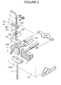
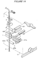
- FIGs 4 to 14 are perspective views illustrating the sliver piecing operation performed by the piecing device.
- Figure 4 shows a standby state of the sliver piecing device 41.
- the sliver piecing device 41 comprises a piecing main body h1.
- the piecing main body h1 comprises a pair of piecing members 1, 1'.
- each of the piecing members 1, 1' is composed of a plate-like member.
- Roller pair portions h20, h20a are provided above and below, respectively, the piecing members 1, 1'.
- roller pair portions h20, h20a sandwich the new sliver S' and the old sliver S between rollers at a position where the new sliver S' and the old sliver S are sandwiched between the piecing members 1, 1'.
- the roller pair portion h20 comprises a driven roller h21 and a rotating roller h22
- the roller pair portion h20a comprises a driven roller h21a and a rotating roller h22a.
- the rotating rollers h22, h22a are fixed to the piecing main body h1 to perform a rotational driving operation.
- the driven rollers h21, h21a are arranged at a 90 degrees position (shown by solid lines) where each of the driven rollers h21, h21a and the corresponding one of the rotating rollers h22, h22a form an L shape.
- the driven rollers h21, h21a move to a position shown by alternate long and two short dashes lines.
- Sensors h23, h24 are arranged between the rotating roller h22 and the driven roller h21 shown by the alternate long and two short dashes line, at the respective ends of the rollers and closer to the piecing members 1, 1' side, respectively (so that the sensors h23, h24 are arranged opposite each other).
- Sensors h23a, h24a are arranged between the rotating roller h22a and the driven roller h21a shown by the alternate long and two short dashes line, at the respective ends of the rollers and closer to the piecing members 1, 1' side, respectively (so that the sensors are arranged opposite each other).
- one of the sensors is a light emitter, while the other is a light receiver.
- a half-moon roller pair portion h30 is provided above the roller pair portion h20.
- the half-moon roller pair portion h30 is composed of half-moon rollers h31, h32.
- the half-moon rollers h31, h32 are arranged in parallel in a direction orthogonal to a shaft of the rotating roller h22.
- the half-moon rollers h31, h32 perform a rotational driving operation.
- the tip side of the half-moon roller pair portion h30 is shaped like a half moon. In a standby state, crescent sides of the half-moon rollers h31, h32 are arranged opposite each other. Thus, a gap is created in the half-moon roller pair portion h30.
- a sandwiching member h40 is provided above the half-moon roller pair portion h30.
- the roller pair portion h20, the half-moon roller pair portion h30, and the sandwiching member h40 are arranged on a vertical line.
- the sandwiching member h40 is composed of a fixed member h42 and a movable member h41.
- the fixed member h42 is fixed to the piecing main body h1.
- the movable member h41 is rotatable around a shaft h43.
- a suction arm b1 sucks and grips the end of the new sliver S' from the full sliver can F, located below, through a suction port b2. Subsequently, the suction arm b1 pivots to a substantially vertically upward position (in the direction of arrow b3) ( Figure 2 ).
- the driven rollers h21, h21a move (in the directions of arrows h50, h51) and lie in parallel, and are then biased by the rotating rollers h22, h22a, respectively.
- the new sliver S' guided by the suction arm b1 is sandwiched between the driven roller h21a and the rotating roller h22a, and between the driven roller h21 and the rotating roller h22.
- the rotating rollers h22, h22a of the roller pair portions h20, h20a rotate (in the directions of arrows h53, h55) to drivingly rotate the driven rollers h21, h21a of the roller pair portions h20, h20a, respectively, (in the directions of arrows h54, h56).
- the new sliver S' sandwiched between the rotating roller h22 and the driven roller h21, and between the rotating roller h22a and the driven roller h21a is pulled between the roller pair portions h20, h20a so that the upper side is pulled in the direction of arrow h64, while the lower side is pulled in the direction of arrow h65.
- the new sliver S' is thus torn and cut between the roller pair portions h20, h20a.
- the sensors h23, h24 detects the end of the new sliver S', and the rotating roller h22 continues to perform a predetermined rotation.
- the upper side of the new sliver S' is thus sucked into the suction port b2 and then into a dust box (not shown in the drawings).
- the driven roller h21 moves (in the direction of arrow h52) back to the standby state shown by the alternate long and two short dashes line.
- the piecing main body h1 comprises an appropriate number of wheels h2 and can reciprocate along a rail v1 disposed on the sliver piecing vehicle 4. The piecing main body h1 then moves (in the direction of arrow h66).
- the old sliver S is located at the sandwiching position where the old sliver S is sandwiched between the fixed member h42 and the movable member h41 of the sandwiching member h40, the gap position where the crescent sides of the half-moon rollers h31, h32 of the half-moon roller pair portion h30 are arranged opposite each other, and the sandwiching portion where the old sliver S is sandwiched between the rotating roller h22 and the driven roller h21 of the roller pair portion h20.
- the rotating roller h22 of the roller pair portion h20 rotates (in the direction of arrow h57).
- the driven roller h21 rotates in conjunction with the rotating roller h22 (in the direction of arrow h58).
- the old sliver S sandwiched between the roller pair portion h20 and the sandwiching member h40 is pulled between the roller pair portion h20 and the sandwiching member h40.
- the old sliver S is torn and cut between the roller pair portion h20 and the sandwiching portion h40.
- the sensors h23, h24 sense the end of the old sliver S.
- roller pair portion h20 continues to perform a predetermined rotation. This portion of the old sliver S is dropped and discharged into the empty sliver can (in the direction of arrow h59). The piecing main body h1 then moves (in the direction of arrow h68).
- the half-moon roller h31 of the half-moon roller pair portion h30 moves in the direction of arrow h61, while the half-moon roller h32 of the half-moon roller pair portion h30 moves in the direction of arrow h60.
- the half-moon rollers h31, h32 of the half-moon roller pair portion h30 sandwich the old sliver S between the arc portions thereof to convey the end of the old sliver S in the direction of arrow h62.
- the old sliver S is reliably conveyed by the rotating roller h22 rotating in the direction of arrow h57 and by the driven roller h21 rotating in the direction of arrow h58.
- the end of the old sliver S is sandwiched between the rotating roller h22 and the driven roller h21.
- the half-moon roller pair portion h30 stops to release the old sliver S.
- the rotating roller h22 of the roller pair portion h20 performs a predetermined rotation (in the direction of arrow h57).
- the rotating roller h22a of the roller pair portion h20a performs a predetermined rotation (in the direction of arrow h55).
- the end of the old sliver S sandwiched between the rollers of the roller pair portion h20 is conveyed in the direction of arrow h62.
- the end of the new sliver S' sandwiched between the rollers of the roller pair portion h20a is conveyed in the direction of arrow h63.
- the ends of the new sliver S' and the old sliver S are conveyed to the piecing portions 1, 1'.
- the ends of the new sliver S' and the old sliver S fed to the piecing portions 1, 1' are arranged so as not to collide against each other.
- the rotating rollers h22, h22a are rotationally controlled such that the new sliver S' and the old sliver S are fed to the piecing portions 1, 1' by a predetermined length so as to form an even pieced portion between the new sliver S' and the old sliver S after piecing.
- the piecing members 1, 1' are coupled to sliding members h5, h5' via a pin h4 respectively.
- the piecing members 1, 1' are biased (open) so as to leave each other in opposite directions by means of appropriate spring members such as coil springs which are provided on the pin h4.
- the piecing main body h1 comprises guide blocks h6, h6'.
- Each of the guide blocks h6, h6' comprises a guide groove h7 in an axial direction.
- Each of the sliding members h5, h5' is inserted and fitted into the guide groove h7.
- the piecing member h1 comprises a lever h10.
- the lever h10 is rotatable around a shaft h9 provided upright in the vertical direction.
- the piecing main body h1 comprises rods h8, h8'.
- One end of each of the rods h8, h8' is coupled to the sliding member h5, h5', and the other end is coupled to a corresponding one of the opposite ends of the lever h10.
- Each of the piecing members 1, 1' comprises a presser member h11 on a rear surface side (opposite the sandwiching surface).
- the presser members h11 press the piecing members 1, 1' via appropriate numbers of rotating rollers h12, h13, respectively.
- the presser members h11 move rotationally around shafts h14, h14', respectively, provided upright on the piecing main body h1.
- a predetermined driving device allows the presser members h11 to pivot around the shafts h14, h14', respectively, in the direction in which the presser members h11 approach each other.
- the presser members h11 move (close) the piecing members 1, 1' via the rotating rollers h12, h13 so that the piecing members 1, 1' approach each other.
- the piecing members 1, 1' sandwich the ends of the new sliver S' and the old sliver S between the piecing members 1, 1'.
- the predetermined driving device swingably moves the lever h10 around the shaft h9.
- the sliding members h5, h5' thus slide along the guide grooves h7 in the guide blocks h6, h6', respectively.
- the piecing members 1, 1' then slide alternately in sliding directions (lateral directions) 1b, 1b' orthogonal to a yarn path direction (vertical direction) to rub against each other.
- the piecing members 1, 1' thus rub and piece the ends of the new sliver S' and the old sliver S sandwiched between the piecing members 1, 1'.
- the rotating rollers h12, h13, disposed on the presser members h11, allow the piecing members 1, 1' to rub smoothly against each other.
- Figure 15 is a diagram illustrating the piecing members.
- Figure 15A is a diagram showing that the piecing members 1, 1' are open (the slivers S, S' are not sandwiched between the piecing members 1, 1').
- Figure 15B is a diagram showing that the piecing members 1, 1' are closed (the slivers S, S' are sandwiched between the piecing members 1, 1').
- the piecing members 1, 1' are plate-like members having the same rectangular shape.
- the piecing members 1, 1' comprises sandwiching surfaces 1a, 1a' between which the slivers S, S' are sandwiched ( Figure 15A ).
- the sandwiching surfaces 1a, 1a' of the piecing members 1, 1' stand opposite each other to sandwich the slivers S, S' between the sandwiching surfaces 1a, 1a'.
- Figure 15C is a sectional view taken along line I-I in Figure 15B .
- the old sliver S extends from above to below.
- the end S11 of the old sliver S is located substantially all over the sandwiching surfaces 1a, 1a' in the vertical direction.
- the new sliver S' extends from below to above.
- the end S11 of the old sliver S' is located substantially all over the sandwiching surfaces 1a, 1a' in the vertical direction.
- the ends S11, S11' of the slivers S, S' are overlappingly arranged substantially all over the sandwiching surfaces 1a, 1a' in the vertical direction. Therefore, the tip S12 of the old sliver S is located at the bottom of the sandwiching surfaces 1a, 1a'.
- the tip S12' of the new sliver S' is located at the top of the sandwiching surfaces 1a, 1a'.
- the piecing members 1, 1' comprise entanglement preventing grooves 10, 10' formed in central portions of the sandwiching surfaces 1a, 1a', respectively, in the yarn path direction (vertical direction) S10 so as to extend in the sliding direction (lateral direction) 1b, 1b'.
- the entanglement preventing groove portions 10, 10' are formed relatively deep. With the slivers S, S' sandwiched between the piecing members 1, 1', the entanglement preventing groove portions 10, 10' form areas in which the slivers S, S' are not sandwiched (space portions 10, 10') and which correspond to the central portions of the sliver ends S11, S11' ( Figure 15C ).
- the central portions of the sliver ends S11, S11' are prevented from being rubbed by the entanglement preventing groove portions (space portions) 10, 10' and remain in the yarn path direction S10 without being entangled with each other.
- the slivers S, S' are rubbed above and below the entanglement preventing groove portions 10, 10' on the sandwiching surfaces 1a, 1a'. Consequently, the sliver tips S12, S12' of the slivers S, S', which are arranged above and below the entanglement preventing groove portions 10, 10', are sandwiched between the sandwiching surfaces 1a, 1a' and rubbed and entangled with each other.
- one of the piecing members 1, 1' comprises entangling groove portions 11, 11 above and below the entanglement preventing groove portions 10 on the sandwiching surface 1a.
- the piecing members 1, 1' comprise resisting members 12, 12' above and below the entanglement preventing groove portions 10, 10' on the sandwiching surfaces 1a, 1a', respectively;
- the resisting members 12, 12' are rubber sheets or the like and exhibit a predetermined slipperiness and a predetermined adhesion.
- the sliver ends S11, S11' are likely to be rubbed and entangled with each other above and below the entanglement preventing groove portions 10, 10' on the sandwiching surfaces 1a, 1a', respectively. Consequently, the sliver tips S12, S12' are firmly and stably entangled with the slivers S, S'.
Landscapes
- Engineering & Computer Science (AREA)
- Mechanical Engineering (AREA)
- Textile Engineering (AREA)
- Spinning Or Twisting Of Yarns (AREA)
Abstract
Description
- The present invention relates to a sliver piecing device that pieces an old sliver from an empty sliver can and a new sliver from a full sliver can together.
- Sliver cans are arranged behind a spinning machine so that slivers from the sliver cans are supplied to the spinning machine for spinning. When the sliver can from which the sliver is being supplied becomes substantially empty (the empty sliver can), a predetermined vehicle replaces the empty sliver can with a sliver can full of sliver (a full sliver can). During the replacement, a sliver piecing device provided on the vehicle pieces an end of the sliver (old sliver) from the empty sliver can and an end of the sliver (new sliver) from the full sliver can together. Thus, the spinning machine can continuously supply the sliver. The sliver piecing device comprises a pair of piecing members that pieces the ends of the slivers together (reference numerals h3, h3' shown in
Figure 10 and other figures in the Unexamined Japanese Patent Application Publication (Tokkai-Hei) No.9-105036 - The piecing members slide alternately with the ends of the slivers sandwiched between the piecing members to rub and piece the ends together. The piecing members have flat surfaces (sandwiching surfaces) between which the sliver ends are sandwiched and rubbed. Thus, the entire sliver ends are evenly rubbed. Consequently, a pieced portion between the sliver ends may exhibit an insufficient or unstable strength depending on the number of fibers in the slivers. Then, disadvantageously, the pieced portion of the slivers may fail to be evenly drafted by a draft device or the pieced portion may be blocked in a spindle of the spinning machine.
- Thus, an object of the present invention is to provide a sliver piecing device capable of stably piecing the ends of the slivers together so that the resulting slivers exhibit the required strength, in order to solve the above-described problems.
- To accomplish the object, a sliver piecing device according to the present invention comprises a pair of piecing members that slide alternately with the sliver ends sandwiched between the piecing members to rub and piece the sliver ends together.
- The piecing members both comprise respective entanglement preventing groove portions preventing entanglement during rubbing, on respective surfaces between which the sliver ends are sandwiched.
- Each of the entanglement preventing groove portions is formed in a central portion of the sandwiching surface so as to extend in a sliding direction.
- Preferably, any one of the piecing members comprises a groove portion on each of opposite side portions of the entanglement preventing groove portion on the sandwiching surface.
- Preferably, each of the piecing members comprises a resisting portion on each of the opposite side portions of the entanglement preventing groove portion on the sandwiching surface.
- According to the present invention, as described above, the piecing members both comprise the respective entanglement preventing groove portions preventing entanglement during rubbing, on the respective surfaces between which the sliver ends are sandwiched. Moreover, each of the entanglement preventing groove portions is formed in the central portion of the sandwiching surface so as to extend in the sliding direction. Thus, even though the slivers are sandwiched between the piecing members, the entanglement preventing groove portions form a space portion. Consequently, in the space portion (entanglement preventing groove potions), the sliver ends are prevented from being rubbed and are thus unlikely to be entangled with each other. The sliver ends are rubbed and entangled with each other on the opposite ends of each of the entanglement preventing groove portion (space portion).
- That is, in the entanglement preventing groove portions (space portion), the direction of fibers in the sliver ends remains along the direction of a yarn path. The sliver ends are rubbed on the opposite sides of each of the entanglement preventing groove portions and entangled with each other in a direction orthogonal to the yarn path. Consequently, tips of the sliver ends are entangled with the sliver ends, significantly improving and stabilizing piecing strength regardless of the number of fibers in the sliver.
- Other features, elements, processes, steps, characteristics and advantages of the present invention will become more apparent from the following detailed description of preferred embodiments of the present invention with reference to the attached drawings.
-
-
Figure 1 is a plan view showing a spinning system. -
Figure 2 is a front view showing the spinning system. -
Figure 3 is a front view showing the spinning system. -
Figure 4 is a perspective view illustrating a sliver piecing operation performed by a piecing device. -
Figure 5 is a perspective view continued fromFigure 4 . -
Figure 6 is a perspective view continued fromFigure 5 . -
Figure 7 is a perspective view continued fromFigure 6 . -
Figure 8 is a perspective view continued fromFigure 7 . -
Figure 9 is a perspective view continued fromFigure 8 . -
Figure 10 is a perspective view continued fromFigure 9 . -
Figure 11 is a perspective view continued fromFigure 10 . -
Figure 12 is a perspective view continued fromFigure 11 . -
Figure 13 is a perspective view continued fromFigure 12 . -
Figure 14 is a perspective view continued fromFigure 13 . -
Figure 15 is a diagram illustrating a piecing member. - A sliver piecing device according to the present invention will be described with reference to the drawings.
-
Figure 1 is a plan view showing a spinning system.Figure 2 andFigure 3 are front views showing the spinning system. As shown inFigure 1 , the spinning system comprises a rotor-type openend spinning machine 3. Thespinning machine 3 comprises a plurality ofspinning units 30. As shown inFigure 2 , a sliver can C in which sliver S is housed is located under each of thespinning units 30. Thespinning unit 30 traverses the sliver S drawn out of the sliver can C while twisting the sliver S to wind thesliver 32 into a package. - The spinning system comprises a sliver piecing vehicle 4. As shown in
Figure 1 , the sliver piecing vehicle 4 circulates around the periphery of thespinning machine 3 along aguide rail 43. As shown inFigure 2 , theguide rail 43 is provided on a ceiling. The sliver piecing vehicle 4 comprises aconveying device 42 at the top thereof. Theconveying device 42 is coupled to theguide rail 43. The sliver piecing vehicle 4 is conveyed by the hangingconveying device 42. - The spinning system comprises a
control section 5. Thecontrol section 5 controls the operation of thespinning machine 3 and the sliver piecing vehicle 4. The spinning system comprises a detecting device (not shown in the drawings) composed of an operation time managing device, a sensor, and the like to detect that the sliver can C has become substantially empty. When the detecting device detects that the sliver can C has become substantially empty, thecontrol section 5 gives an instruction to thespinning machine 3 and the sliver piecing vehicle 4 to perform operations described below. - The sliver piecing vehicle 4 circulates with the sliver can F full of sliver S' ("full sliver can") mounted thereon. The sliver piecing vehicle 4 has a
placement space 44 located adjacent to the full sliver can F (Figure 1 ). Theplacement space 44 is a space in which an empty sliver can E is placed. On the basis of an instruction from thecontrol section 5, the sliver piecing vehicle 4 stops at the spinning unit 30 (hereinafter referred to as the "target spinning unit") for the can E in which the sliver S is to be exhausted (this sliver can is hereinafter referred to as the "empty sliver can") (Figure 1A ). - The
target spinning unit 30 stops a spinning operation to stop the supply of the sliver S from the empty can E. As shown inFigure 2 , the spinningunit 30 comprises a belt conveyor-type sliver can replacingdevice 31 at the bottom thereof. Similarly, the sliver piecing vehicle 4 comprises a belt conveyor-type sliver can replacingdevice 40 at the bottom thereof. As shown inFigures 1A and2 , the sliver can replacingdevices target spinning unit 30 to theplacement space 44 on the sliver piecing vehicle 4. - The sliver piecing vehicle 4 comprises a
sliver piecing device 41. Although described below in detail, thesliver piecing device 41 grips an end of the sliver (hereinafter referred to as the "new sliver") S' from the full sliver can F (Figure 2 ). Then, thesliver piecing device 41 uses a drawing hook t10 to draw the sliver (hereinafter referred to as the "old sliver") S from the empty sliver can E closer to thesliver piecing device 41. Thesliver piecing device 41 then pieces the old sliver S (the empty sliver can E is located closer to the reader inFigure 3 ) and the new sliver S' (the full sliver can F is located farther from the reader inFigure 3 ). - After the sliver piecing operation for the old sliver S and the new sliver S' is completed, the
sliver piecing device 41 uses a discharging hook (not shown in the drawings) to move the slivers subjected to the sliver piecing, toward thespinning unit 30. In synchronism with this movement, as shown inFigure 1B , the sliver piecing vehicle 4 moves slightly forward and uses the sliver can replacingdevices -
Figures 4 to 14 are perspective views illustrating the sliver piecing operation performed by the piecing device.Figure 4 shows a standby state of thesliver piecing device 41. Thesliver piecing device 41 comprises a piecing main body h1. The piecing main body h1 comprises a pair of piecingmembers 1, 1'. Although described below in detail, each of thepiecing members 1, 1' is composed of a plate-like member. Roller pair portions h20, h20a are provided above and below, respectively, the piecingmembers 1, 1'. The roller pair portions h20, h20a sandwich the new sliver S' and the old sliver S between rollers at a position where the new sliver S' and the old sliver S are sandwiched between the piecingmembers 1, 1'. - The roller pair portion h20 comprises a driven roller h21 and a rotating roller h22, and the roller pair portion h20a comprises a driven roller h21a and a rotating roller h22a. The rotating rollers h22, h22a are fixed to the piecing main body h1 to perform a rotational driving operation. During standby, the driven rollers h21, h21a are arranged at a 90 degrees position (shown by solid lines) where each of the driven rollers h21, h21a and the corresponding one of the rotating rollers h22, h22a form an L shape. To sandwich the slivers between the rollers, the driven rollers h21, h21a move to a position shown by alternate long and two short dashes lines.
- Sensors h23, h24 are arranged between the rotating roller h22 and the driven roller h21 shown by the alternate long and two short dashes line, at the respective ends of the rollers and closer to the
piecing members 1, 1' side, respectively (so that the sensors h23, h24 are arranged opposite each other). Sensors h23a, h24a are arranged between the rotating roller h22a and the driven roller h21a shown by the alternate long and two short dashes line, at the respective ends of the rollers and closer to thepiecing members 1, 1' side, respectively (so that the sensors are arranged opposite each other). For each of the pair of the sensors h23, h24 and the pair of the sensors h23a, h24a, one of the sensors is a light emitter, while the other is a light receiver. - A half-moon roller pair portion h30 is provided above the roller pair portion h20. The half-moon roller pair portion h30 is composed of half-moon rollers h31, h32. The half-moon rollers h31, h32 are arranged in parallel in a direction orthogonal to a shaft of the rotating roller h22. In the roller pair portion h30, the half-moon rollers h31, h32 perform a rotational driving operation. The tip side of the half-moon roller pair portion h30 is shaped like a half moon. In a standby state, crescent sides of the half-moon rollers h31, h32 are arranged opposite each other. Thus, a gap is created in the half-moon roller pair portion h30.
- A sandwiching member h40 is provided above the half-moon roller pair portion h30. The roller pair portion h20, the half-moon roller pair portion h30, and the sandwiching member h40 are arranged on a vertical line. The sandwiching member h40 is composed of a fixed member h42 and a movable member h41. The fixed member h42 is fixed to the piecing main body h1. The movable member h41 is rotatable around a shaft h43.
- As shown in
Figure 5 , in this standby state, a suction arm b1 sucks and grips the end of the new sliver S' from the full sliver can F, located below, through a suction port b2. Subsequently, the suction arm b1 pivots to a substantially vertically upward position (in the direction of arrow b3) (Figure 2 ). - As shown in
Figure 6 , the driven rollers h21, h21a move (in the directions of arrows h50, h51) and lie in parallel, and are then biased by the rotating rollers h22, h22a, respectively. The new sliver S' guided by the suction arm b1 is sandwiched between the driven roller h21a and the rotating roller h22a, and between the driven roller h21 and the rotating roller h22. - As shown in
Figure 7 , the rotating rollers h22, h22a of the roller pair portions h20, h20a, respectively, rotate (in the directions of arrows h53, h55) to drivingly rotate the driven rollers h21, h21a of the roller pair portions h20, h20a, respectively, (in the directions of arrows h54, h56). The new sliver S' sandwiched between the rotating roller h22 and the driven roller h21, and between the rotating roller h22a and the driven roller h21a is pulled between the roller pair portions h20, h20a so that the upper side is pulled in the direction of arrow h64, while the lower side is pulled in the direction of arrow h65. The new sliver S' is thus torn and cut between the roller pair portions h20, h20a. - For the upper side of the cut new sliver S', the sensors h23, h24 detects the end of the new sliver S', and the rotating roller h22 continues to perform a predetermined rotation. The upper side of the new sliver S' is thus sucked into the suction port b2 and then into a dust box (not shown in the drawings). The driven roller h21 moves (in the direction of arrow h52) back to the standby state shown by the alternate long and two short dashes line.
- On the other hand, when the sensor h23a, h24a detects the lower end of the cut new sliver S', the driving of the rotating roller h22a is stopped. The rotating roller h22a and the driven roller h21a are then stopped with the end of the new sliver S' sandwiched between the rollers. Thus, a sliver piecing end is formed on the new sliver S' and located at a sliver piecing position.
- Then, as shown in
Figure 8 , the old sliver S is transferred to the sliver piecing position by the drawing hook t10 (Figure 3 ). The piecing main body h1 comprises an appropriate number of wheels h2 and can reciprocate along a rail v1 disposed on the sliver piecing vehicle 4. The piecing main body h1 then moves (in the direction of arrow h66). - The old sliver S is located at the sandwiching position where the old sliver S is sandwiched between the fixed member h42 and the movable member h41 of the sandwiching member h40, the gap position where the crescent sides of the half-moon rollers h31, h32 of the half-moon roller pair portion h30 are arranged opposite each other, and the sandwiching portion where the old sliver S is sandwiched between the rotating roller h22 and the driven roller h21 of the roller pair portion h20.
- As shown in
Figure 9 , in this state, the movable member h41 of the sandwiching member h40 moves (in the direction of arrow h67) so that the old sliver S is sandwiched between the fixed member h42 and the movable member h41. The driven roller h21 of the roller pair portion h20 moves (in the direction of arrow h51) so that the old sliver S is sandwiched between the rotating roller h22 and the driven roller h21. - As shown in
Figure 10 , in this state, the rotating roller h22 of the roller pair portion h20 rotates (in the direction of arrow h57). The driven roller h21 rotates in conjunction with the rotating roller h22 (in the direction of arrow h58). In conjunction with the rotation, the old sliver S sandwiched between the roller pair portion h20 and the sandwiching member h40 is pulled between the roller pair portion h20 and the sandwiching member h40. The old sliver S is torn and cut between the roller pair portion h20 and the sandwiching portion h40. For the unwanted lower side of the cut old sliver S, the sensors h23, h24 sense the end of the old sliver S. Then, the roller pair portion h20 continues to perform a predetermined rotation. This portion of the old sliver S is dropped and discharged into the empty sliver can (in the direction of arrow h59). The piecing main body h1 then moves (in the direction of arrow h68). - As shown in
Figure 11 , in this state, the movable member h41 of the sandwiching member h40 moves (in the direction of arrow h69) to release the old sliver S. The end of the old sliver S falls toward the roller pair portion h20 owing to the slack and weight of the old sliver S. - Then, the half-moon roller h31 of the half-moon roller pair portion h30 moves in the direction of arrow h61, while the half-moon roller h32 of the half-moon roller pair portion h30 moves in the direction of arrow h60. Thus, the half-moon rollers h31, h32 of the half-moon roller pair portion h30 sandwich the old sliver S between the arc portions thereof to convey the end of the old sliver S in the direction of arrow h62. The old sliver S is reliably conveyed by the rotating roller h22 rotating in the direction of arrow h57 and by the driven roller h21 rotating in the direction of arrow h58. The end of the old sliver S is sandwiched between the rotating roller h22 and the driven roller h21. When the standby state is established where the crescent portions of the half-moon rollers h31, h32 lie opposite each other, the half-moon roller pair portion h30 stops to release the old sliver S.
- Then, as shown in
Figure 12 , the rotating roller h22 of the roller pair portion h20 performs a predetermined rotation (in the direction of arrow h57). The rotating roller h22a of the roller pair portion h20a performs a predetermined rotation (in the direction of arrow h55). Then, the end of the old sliver S sandwiched between the rollers of the roller pair portion h20 is conveyed in the direction of arrow h62. On the other hand, the end of the new sliver S' sandwiched between the rollers of the roller pair portion h20a is conveyed in the direction of arrow h63. - Thus, the ends of the new sliver S' and the old sliver S are conveyed to the
piecing portions 1, 1'. The ends of the new sliver S' and the old sliver S fed to thepiecing portions 1, 1' are arranged so as not to collide against each other. The rotating rollers h22, h22a are rotationally controlled such that the new sliver S' and the old sliver S are fed to thepiecing portions 1, 1' by a predetermined length so as to form an even pieced portion between the new sliver S' and the old sliver S after piecing. - As shown in
Figure 13 , the piecingmembers 1, 1' are coupled to sliding members h5, h5' via a pin h4 respectively. In the standby state, the piecingmembers 1, 1' are biased (open) so as to leave each other in opposite directions by means of appropriate spring members such as coil springs which are provided on the pin h4. The piecing main body h1 comprises guide blocks h6, h6'. Each of the guide blocks h6, h6' comprises a guide groove h7 in an axial direction. Each of the sliding members h5, h5' is inserted and fitted into the guide groove h7. - The piecing member h1 comprises a lever h10. The lever h10 is rotatable around a shaft h9 provided upright in the vertical direction. The piecing main body h1 comprises rods h8, h8'. One end of each of the rods h8, h8' is coupled to the sliding member h5, h5', and the other end is coupled to a corresponding one of the opposite ends of the lever h10. Each of the
piecing members 1, 1' comprises a presser member h11 on a rear surface side (opposite the sandwiching surface). The presser members h11 press the piecingmembers 1, 1' via appropriate numbers of rotating rollers h12, h13, respectively. The presser members h11 move rotationally around shafts h14, h14', respectively, provided upright on the piecing main body h1. - A predetermined driving device (not shown in the drawings) allows the presser members h11 to pivot around the shafts h14, h14', respectively, in the direction in which the presser members h11 approach each other. Thus, the presser members h11 move (close) the
piecing members 1, 1' via the rotating rollers h12, h13 so that thepiecing members 1, 1' approach each other. The piecingmembers 1, 1' sandwich the ends of the new sliver S' and the old sliver S between the piecingmembers 1, 1'. - Subsequently, the predetermined driving device (not shown in the drawings) swingably moves the lever h10 around the shaft h9. The sliding members h5, h5' thus slide along the guide grooves h7 in the guide blocks h6, h6', respectively. The piecing
members 1, 1' then slide alternately in sliding directions (lateral directions) 1b, 1b' orthogonal to a yarn path direction (vertical direction) to rub against each other. The piecingmembers 1, 1' thus rub and piece the ends of the new sliver S' and the old sliver S sandwiched between the piecingmembers 1, 1'. The rotating rollers h12, h13, disposed on the presser members h11, allow thepiecing members 1, 1' to rub smoothly against each other. - After the piecing of the old sliver S and the new sliver S' is completed, as shown in
Figure 14 , an operation is performed to open the piecingmembers 1, 1' as in the case of the standby state and to release the new sliver S' and the old sliver S from the roller pair portions h20, h20a. Moreover, all the members are returned to the standby states thereof. Then, the sliver piecing process is completed. -
Figure 15 is a diagram illustrating the piecing members.Figure 15A is a diagram showing that thepiecing members 1, 1' are open (the slivers S, S' are not sandwiched between the piecingmembers 1, 1').Figure 15B is a diagram showing that thepiecing members 1, 1' are closed (the slivers S, S' are sandwiched between the piecingmembers 1, 1'). - The piecing
members 1, 1' are plate-like members having the same rectangular shape. The piecingmembers 1, 1' comprises sandwichingsurfaces Figure 15A ). The sandwiching surfaces 1a, 1a' of thepiecing members 1, 1' stand opposite each other to sandwich the slivers S, S' between the sandwichingsurfaces surfaces Figure 15B ), the piecingmembers 1, 1' slide alternately or only one of thepiecing members 1, 1' slides, in the direction orthogonal (lateral direction) 1b, 1b' to the yarn path direction (vertical direction) S10 of the slivers S, S' to rub against each other. Then, as described above, the slivers S, S' are entangled with and pieced to each other (Figure 13 ). -
Figure 15C is a sectional view taken along line I-I inFigure 15B . The old sliver S extends from above to below. The end S11 of the old sliver S is located substantially all over the sandwichingsurfaces surfaces surfaces surfaces surfaces - The piecing
members 1, 1' compriseentanglement preventing grooves 10, 10' formed in central portions of the sandwichingsurfaces groove portions 10, 10' are formed relatively deep. With the slivers S, S' sandwiched between the piecingmembers 1, 1', the entanglement preventinggroove portions 10, 10' form areas in which the slivers S, S' are not sandwiched (space portions 10, 10') and which correspond to the central portions of the sliver ends S11, S11' (Figure 15C ). Consequently, the ends S11, S11' of the slivers S, S' are not sandwiched between the sandwichingsurfaces - Thus, even though the
piecing members 1, 1' slide, the central portions of the sliver ends S11, S11' are prevented from being rubbed by the entanglement preventing groove portions (space portions) 10, 10' and remain in the yarn path direction S10 without being entangled with each other. The slivers S, S' are rubbed above and below the entanglement preventinggroove portions 10, 10' on the sandwiching surfaces 1a, 1a'. Consequently, the sliver tips S12, S12' of the slivers S, S', which are arranged above and below the entanglement preventinggroove portions 10, 10', are sandwiched between the sandwichingsurfaces - Thus, as shown in
Figure 15D , the central portions of the ends S11, S11' of the slivers S, S' are prevented from being rubbed or entangled with each other and remain arranged in the yarn path direction (vertical direction) S10. The tips S12, S12' are rubbed and shifted in the lateral direction and thus entangled with the slivers S, S'. Consequently, the tips S12, S12' of the slivers S, S' are entangled with the sliver ends S11, S11'. Piecing strength is thus significantly improved and stabilized regardless of the number of fibers members or the like. - Furthermore, one of the
piecing members 1, 1', that is, the piecingmember 1, comprises entanglinggroove portions groove portions 10 on thesandwiching surface 1a. Moreover, the piecingmembers 1, 1'comprise resisting members 12, 12' above and below the entanglement preventinggroove portions 10, 10' on the sandwiching surfaces 1a, 1a', respectively; the resistingmembers 12, 12' are rubber sheets or the like and exhibit a predetermined slipperiness and a predetermined adhesion. Thus, the sliver ends S11, S11' are likely to be rubbed and entangled with each other above and below the entanglement preventinggroove portions 10, 10' on the sandwiching surfaces 1a, 1a', respectively. Consequently, the sliver tips S12, S12' are firmly and stably entangled with the slivers S, S'. - While the present invention has been described with respect to preferred embodiments thereof, it will be apparent to those skilled in the art that the disclosed invention may be modified in numerous ways and may assume many embodiments other than those specifically set out and described above. Accordingly, it is intented by the appended claims to cover all modifications of the present invention that fall within the true spirit and scope of the invention.
Claims (3)
- A sliver piecing device that pieces a pair of slivers together, the device being characterized by comprising a pair of piecing members that slide alternately with sliver ends sandwiched between said piecing members to rub and piece said sliver ends together, and
in that said piecing members both comprise respective entanglement preventing groove portions preventing entanglement during rubbing, on respective surfaces between which said sliver ends are sandwiched, and each of said entanglement preventing groove portions is formed in a central portion of said sandwiching surface so as to extend in a sliding direction. - A sliver piecing device according to Claim 1, characterized in that any one of said piecing members comprises a groove portion on each of opposite side portions of said entanglement preventing groove portion on said sandwiching surface.
- A sliver piecing device according to Claim 1 or Claim 2, characterized in that each of said piecing members comprises a resisting portion on each of the opposite side portions of said entanglement preventing groove portion on said sandwiching surface.
Applications Claiming Priority (1)
| Application Number | Priority Date | Filing Date | Title |
|---|---|---|---|
| JP2007213340A JP4962726B2 (en) | 2007-08-20 | 2007-08-20 | Sliver splicing device |
Publications (3)
| Publication Number | Publication Date |
|---|---|
| EP2028304A2 true EP2028304A2 (en) | 2009-02-25 |
| EP2028304A3 EP2028304A3 (en) | 2014-02-19 |
| EP2028304B1 EP2028304B1 (en) | 2015-08-05 |
Family
ID=40225321
Family Applications (1)
| Application Number | Title | Priority Date | Filing Date |
|---|---|---|---|
| EP08011813.6A Ceased EP2028304B1 (en) | 2007-08-20 | 2008-06-30 | Sliver piecing device |
Country Status (2)
| Country | Link |
|---|---|
| EP (1) | EP2028304B1 (en) |
| JP (1) | JP4962726B2 (en) |
Citations (1)
| Publication number | Priority date | Publication date | Assignee | Title |
|---|---|---|---|---|
| JPH09105036A (en) | 1995-10-04 | 1997-04-22 | Murata Mach Ltd | Sliver-piecing apparatus |
Family Cites Families (9)
| Publication number | Priority date | Publication date | Assignee | Title |
|---|---|---|---|---|
| JPH03193942A (en) * | 1989-12-21 | 1991-08-23 | Murata Mach Ltd | Joining method of sliver |
| JPH0681229A (en) * | 1992-09-01 | 1994-03-22 | Murata Mach Ltd | Sliver-ending apparatus |
| JPH0681230A (en) * | 1992-09-01 | 1994-03-22 | Murata Mach Ltd | Sliver-ending apparatus |
| JP3003417B2 (en) * | 1992-09-25 | 2000-01-31 | 村田機械株式会社 | Sliver splicing device |
| US5535581A (en) * | 1993-04-22 | 1996-07-16 | Murata Kikai Kabushiki Kaisha | Sliver cans exchanging system and sliver piecing system |
| JPH07118968A (en) * | 1993-10-26 | 1995-05-09 | Murata Mach Ltd | Silver ending device |
| JP2636708B2 (en) * | 1993-10-29 | 1997-07-30 | 村田機械株式会社 | Sliver splicing method |
| JPH101830A (en) * | 1996-06-10 | 1998-01-06 | Murata Mach Ltd | Sliver ending apparatus |
| EP1219737B2 (en) * | 2000-12-22 | 2012-01-18 | Maschinenfabrik Rieter Ag | Procedure for piecing up or joining a yarn created in a spinning station, said spinning station being equiped to carry out the procedure |
-
2007
- 2007-08-20 JP JP2007213340A patent/JP4962726B2/en not_active Expired - Fee Related
-
2008
- 2008-06-30 EP EP08011813.6A patent/EP2028304B1/en not_active Ceased
Patent Citations (1)
| Publication number | Priority date | Publication date | Assignee | Title |
|---|---|---|---|---|
| JPH09105036A (en) | 1995-10-04 | 1997-04-22 | Murata Mach Ltd | Sliver-piecing apparatus |
Also Published As
| Publication number | Publication date |
|---|---|
| JP2009046771A (en) | 2009-03-05 |
| EP2028304B1 (en) | 2015-08-05 |
| JP4962726B2 (en) | 2012-06-27 |
| EP2028304A3 (en) | 2014-02-19 |
Similar Documents
| Publication | Publication Date | Title |
|---|---|---|
| CN101134534B (en) | Card dispensing apparatus | |
| CN202864580U (en) | Connector device and yarn reeling device | |
| EP2793200A1 (en) | Sorting and bundling all-in-one machine and banknote stacking and sorting module thereof | |
| US6530538B2 (en) | Winding device for a textile machine that produces cheeses | |
| EP2263942A2 (en) | Paper sheet processing system | |
| CN106436069B (en) | Full-automatic bobbin thread winding machine | |
| CN103508259A (en) | Take-up winder | |
| EP2028304B1 (en) | Sliver piecing device | |
| EP4282800B1 (en) | Yarn feeding package conveying carriage | |
| CN103010845A (en) | Yarn processing device and yarn winding device | |
| JPH03182444A (en) | Sheet transport device | |
| JP2018127364A (en) | Yarn splicing device for work unit of textile machine for manufacturing cross-wound package | |
| CZ20011458A3 (en) | Thread feeding mechanism with two feeding rollers | |
| CN103171932B (en) | Winding device | |
| EP1980347A1 (en) | Bar feeding apparatus for automatically feeding bars to machine tools, in particular for feeding bars having different diameters | |
| CN105980620B (en) | Sewing object mobile device and its sewing machine | |
| EP0409624A1 (en) | Bobbin transfer apparatus for spinning machines | |
| CN113844953A (en) | Yarn winding machine capable of quantifying yarn and using method thereof | |
| JP5343411B2 (en) | Paper belt feeder and banknote sealing machine | |
| CN107541819B (en) | Cleaning device for drafting roller and drafting device | |
| CN104514058A (en) | Service vehicle of textile machine | |
| CN1865109B (en) | Driving mechanism for transverse moving device | |
| KR102869312B1 (en) | Power transmission structure of media separation unit | |
| CN114104846B (en) | Creel for a winding device of a textile machine for producing cross-wound bobbins | |
| JPH07265568A (en) | Feeding device for machine tool,especially for sewing machine |
Legal Events
| Date | Code | Title | Description |
|---|---|---|---|
| PUAI | Public reference made under article 153(3) epc to a published international application that has entered the european phase |
Free format text: ORIGINAL CODE: 0009012 |
|
| AK | Designated contracting states |
Kind code of ref document: A2 Designated state(s): AT BE BG CH CY CZ DE DK EE ES FI FR GB GR HR HU IE IS IT LI LT LU LV MC MT NL NO PL PT RO SE SI SK TR |
|
| AX | Request for extension of the european patent |
Extension state: AL BA MK RS |
|
| PUAL | Search report despatched |
Free format text: ORIGINAL CODE: 0009013 |
|
| AK | Designated contracting states |
Kind code of ref document: A3 Designated state(s): AT BE BG CH CY CZ DE DK EE ES FI FR GB GR HR HU IE IS IT LI LT LU LV MC MT NL NO PL PT RO SE SI SK TR |
|
| AX | Request for extension of the european patent |
Extension state: AL BA MK RS |
|
| RIC1 | Information provided on ipc code assigned before grant |
Ipc: D01H 15/00 20060101AFI20140116BHEP |
|
| 17P | Request for examination filed |
Effective date: 20140717 |
|
| AKX | Designation fees paid |
Designated state(s): CH DE IT LI |
|
| GRAP | Despatch of communication of intention to grant a patent |
Free format text: ORIGINAL CODE: EPIDOSNIGR1 |
|
| INTG | Intention to grant announced |
Effective date: 20150205 |
|
| GRAS | Grant fee paid |
Free format text: ORIGINAL CODE: EPIDOSNIGR3 |
|
| GRAL | Information related to payment of fee for publishing/printing deleted |
Free format text: ORIGINAL CODE: EPIDOSDIGR3 |
|
| GRAS | Grant fee paid |
Free format text: ORIGINAL CODE: EPIDOSNIGR3 |
|
| GRAA | (expected) grant |
Free format text: ORIGINAL CODE: 0009210 |
|
| AK | Designated contracting states |
Kind code of ref document: B1 Designated state(s): CH DE IT LI |
|
| REG | Reference to a national code |
Ref country code: CH Ref legal event code: EP |
|
| REG | Reference to a national code |
Ref country code: DE Ref legal event code: R096 Ref document number: 602008039354 Country of ref document: DE |
|
| REG | Reference to a national code |
Ref country code: DE Ref legal event code: R082 Ref document number: 602008039354 Country of ref document: DE Representative=s name: WEICKMANN & WEICKMANN PATENTANWAELTE - RECHTSA, DE Ref country code: DE Ref legal event code: R082 Ref document number: 602008039354 Country of ref document: DE Representative=s name: WEICKMANN & WEICKMANN PATENT- UND RECHTSANWAEL, DE |
|
| REG | Reference to a national code |
Ref country code: DE Ref legal event code: R097 Ref document number: 602008039354 Country of ref document: DE |
|
| PLBE | No opposition filed within time limit |
Free format text: ORIGINAL CODE: 0009261 |
|
| STAA | Information on the status of an ep patent application or granted ep patent |
Free format text: STATUS: NO OPPOSITION FILED WITHIN TIME LIMIT |
|
| 26N | No opposition filed |
Effective date: 20160509 |
|
| PGFP | Annual fee paid to national office [announced via postgrant information from national office to epo] |
Ref country code: BG Payment date: 20190614 Year of fee payment: 15 |
|
| PGFP | Annual fee paid to national office [announced via postgrant information from national office to epo] |
Ref country code: CH Payment date: 20200618 Year of fee payment: 13 Ref country code: DE Payment date: 20200618 Year of fee payment: 13 |
|
| PG25 | Lapsed in a contracting state [announced via postgrant information from national office to epo] |
Ref country code: IT Free format text: LAPSE BECAUSE OF NON-PAYMENT OF DUE FEES Effective date: 20200630 |
|
| REG | Reference to a national code |
Ref country code: DE Ref legal event code: R119 Ref document number: 602008039354 Country of ref document: DE |
|
| REG | Reference to a national code |
Ref country code: CH Ref legal event code: PL |
|
| PG25 | Lapsed in a contracting state [announced via postgrant information from national office to epo] |
Ref country code: LI Free format text: LAPSE BECAUSE OF NON-PAYMENT OF DUE FEES Effective date: 20210630 Ref country code: DE Free format text: LAPSE BECAUSE OF NON-PAYMENT OF DUE FEES Effective date: 20220101 Ref country code: CH Free format text: LAPSE BECAUSE OF NON-PAYMENT OF DUE FEES Effective date: 20210630 |