EP2028100A1 - Fastener - Google Patents
Fastener Download PDFInfo
- Publication number
- EP2028100A1 EP2028100A1 EP07745044A EP07745044A EP2028100A1 EP 2028100 A1 EP2028100 A1 EP 2028100A1 EP 07745044 A EP07745044 A EP 07745044A EP 07745044 A EP07745044 A EP 07745044A EP 2028100 A1 EP2028100 A1 EP 2028100A1
- Authority
- EP
- European Patent Office
- Prior art keywords
- fastener
- insulator layer
- skin
- airplane
- flush head
- Prior art date
- Legal status (The legal status is an assumption and is not a legal conclusion. Google has not performed a legal analysis and makes no representation as to the accuracy of the status listed.)
- Granted
Links
Images

Classifications
-
- F—MECHANICAL ENGINEERING; LIGHTING; HEATING; WEAPONS; BLASTING
- F16—ENGINEERING ELEMENTS AND UNITS; GENERAL MEASURES FOR PRODUCING AND MAINTAINING EFFECTIVE FUNCTIONING OF MACHINES OR INSTALLATIONS; THERMAL INSULATION IN GENERAL
- F16B—DEVICES FOR FASTENING OR SECURING CONSTRUCTIONAL ELEMENTS OR MACHINE PARTS TOGETHER, e.g. NAILS, BOLTS, CIRCLIPS, CLAMPS, CLIPS OR WEDGES; JOINTS OR JOINTING
- F16B33/00—Features common to bolt and nut
- F16B33/004—Sealing; Insulation
-
- B—PERFORMING OPERATIONS; TRANSPORTING
- B29—WORKING OF PLASTICS; WORKING OF SUBSTANCES IN A PLASTIC STATE IN GENERAL
- B29C—SHAPING OR JOINING OF PLASTICS; SHAPING OF MATERIAL IN A PLASTIC STATE, NOT OTHERWISE PROVIDED FOR; AFTER-TREATMENT OF THE SHAPED PRODUCTS, e.g. REPAIRING
- B29C65/00—Joining or sealing of preformed parts, e.g. welding of plastics materials; Apparatus therefor
- B29C65/56—Joining or sealing of preformed parts, e.g. welding of plastics materials; Apparatus therefor using mechanical means or mechanical connections, e.g. form-fits
- B29C65/562—Joining or sealing of preformed parts, e.g. welding of plastics materials; Apparatus therefor using mechanical means or mechanical connections, e.g. form-fits using extra joining elements, i.e. which are not integral with the parts to be joined
-
- B—PERFORMING OPERATIONS; TRANSPORTING
- B29—WORKING OF PLASTICS; WORKING OF SUBSTANCES IN A PLASTIC STATE IN GENERAL
- B29C—SHAPING OR JOINING OF PLASTICS; SHAPING OF MATERIAL IN A PLASTIC STATE, NOT OTHERWISE PROVIDED FOR; AFTER-TREATMENT OF THE SHAPED PRODUCTS, e.g. REPAIRING
- B29C65/00—Joining or sealing of preformed parts, e.g. welding of plastics materials; Apparatus therefor
- B29C65/56—Joining or sealing of preformed parts, e.g. welding of plastics materials; Apparatus therefor using mechanical means or mechanical connections, e.g. form-fits
- B29C65/562—Joining or sealing of preformed parts, e.g. welding of plastics materials; Apparatus therefor using mechanical means or mechanical connections, e.g. form-fits using extra joining elements, i.e. which are not integral with the parts to be joined
- B29C65/564—Joining or sealing of preformed parts, e.g. welding of plastics materials; Apparatus therefor using mechanical means or mechanical connections, e.g. form-fits using extra joining elements, i.e. which are not integral with the parts to be joined hidden in the joint, e.g. dowels or Z-pins
-
- B—PERFORMING OPERATIONS; TRANSPORTING
- B29—WORKING OF PLASTICS; WORKING OF SUBSTANCES IN A PLASTIC STATE IN GENERAL
- B29C—SHAPING OR JOINING OF PLASTICS; SHAPING OF MATERIAL IN A PLASTIC STATE, NOT OTHERWISE PROVIDED FOR; AFTER-TREATMENT OF THE SHAPED PRODUCTS, e.g. REPAIRING
- B29C66/00—General aspects of processes or apparatus for joining preformed parts
- B29C66/01—General aspects dealing with the joint area or with the area to be joined
- B29C66/05—Particular design of joint configurations
- B29C66/10—Particular design of joint configurations particular design of the joint cross-sections
- B29C66/11—Joint cross-sections comprising a single joint-segment, i.e. one of the parts to be joined comprising a single joint-segment in the joint cross-section
- B29C66/112—Single lapped joints
- B29C66/1122—Single lap to lap joints, i.e. overlap joints
-
- B—PERFORMING OPERATIONS; TRANSPORTING
- B29—WORKING OF PLASTICS; WORKING OF SUBSTANCES IN A PLASTIC STATE IN GENERAL
- B29C—SHAPING OR JOINING OF PLASTICS; SHAPING OF MATERIAL IN A PLASTIC STATE, NOT OTHERWISE PROVIDED FOR; AFTER-TREATMENT OF THE SHAPED PRODUCTS, e.g. REPAIRING
- B29C66/00—General aspects of processes or apparatus for joining preformed parts
- B29C66/40—General aspects of joining substantially flat articles, e.g. plates, sheets or web-like materials; Making flat seams in tubular or hollow articles; Joining single elements to substantially flat surfaces
- B29C66/41—Joining substantially flat articles ; Making flat seams in tubular or hollow articles
- B29C66/45—Joining of substantially the whole surface of the articles
-
- B—PERFORMING OPERATIONS; TRANSPORTING
- B29—WORKING OF PLASTICS; WORKING OF SUBSTANCES IN A PLASTIC STATE IN GENERAL
- B29C—SHAPING OR JOINING OF PLASTICS; SHAPING OF MATERIAL IN A PLASTIC STATE, NOT OTHERWISE PROVIDED FOR; AFTER-TREATMENT OF THE SHAPED PRODUCTS, e.g. REPAIRING
- B29C66/00—General aspects of processes or apparatus for joining preformed parts
- B29C66/70—General aspects of processes or apparatus for joining preformed parts characterised by the composition, physical properties or the structure of the material of the parts to be joined; Joining with non-plastics material
- B29C66/72—General aspects of processes or apparatus for joining preformed parts characterised by the composition, physical properties or the structure of the material of the parts to be joined; Joining with non-plastics material characterised by the structure of the material of the parts to be joined
- B29C66/721—Fibre-reinforced materials
-
- B—PERFORMING OPERATIONS; TRANSPORTING
- B29—WORKING OF PLASTICS; WORKING OF SUBSTANCES IN A PLASTIC STATE IN GENERAL
- B29C—SHAPING OR JOINING OF PLASTICS; SHAPING OF MATERIAL IN A PLASTIC STATE, NOT OTHERWISE PROVIDED FOR; AFTER-TREATMENT OF THE SHAPED PRODUCTS, e.g. REPAIRING
- B29C66/00—General aspects of processes or apparatus for joining preformed parts
- B29C66/70—General aspects of processes or apparatus for joining preformed parts characterised by the composition, physical properties or the structure of the material of the parts to be joined; Joining with non-plastics material
- B29C66/74—Joining plastics material to non-plastics material
- B29C66/742—Joining plastics material to non-plastics material to metals or their alloys
-
- B—PERFORMING OPERATIONS; TRANSPORTING
- B29—WORKING OF PLASTICS; WORKING OF SUBSTANCES IN A PLASTIC STATE IN GENERAL
- B29C—SHAPING OR JOINING OF PLASTICS; SHAPING OF MATERIAL IN A PLASTIC STATE, NOT OTHERWISE PROVIDED FOR; AFTER-TREATMENT OF THE SHAPED PRODUCTS, e.g. REPAIRING
- B29C66/00—General aspects of processes or apparatus for joining preformed parts
- B29C66/70—General aspects of processes or apparatus for joining preformed parts characterised by the composition, physical properties or the structure of the material of the parts to be joined; Joining with non-plastics material
- B29C66/71—General aspects of processes or apparatus for joining preformed parts characterised by the composition, physical properties or the structure of the material of the parts to be joined; Joining with non-plastics material characterised by the composition of the plastics material of the parts to be joined
-
- B—PERFORMING OPERATIONS; TRANSPORTING
- B29—WORKING OF PLASTICS; WORKING OF SUBSTANCES IN A PLASTIC STATE IN GENERAL
- B29C—SHAPING OR JOINING OF PLASTICS; SHAPING OF MATERIAL IN A PLASTIC STATE, NOT OTHERWISE PROVIDED FOR; AFTER-TREATMENT OF THE SHAPED PRODUCTS, e.g. REPAIRING
- B29C66/00—General aspects of processes or apparatus for joining preformed parts
- B29C66/70—General aspects of processes or apparatus for joining preformed parts characterised by the composition, physical properties or the structure of the material of the parts to be joined; Joining with non-plastics material
- B29C66/72—General aspects of processes or apparatus for joining preformed parts characterised by the composition, physical properties or the structure of the material of the parts to be joined; Joining with non-plastics material characterised by the structure of the material of the parts to be joined
- B29C66/721—Fibre-reinforced materials
- B29C66/7212—Fibre-reinforced materials characterised by the composition of the fibres
-
- B—PERFORMING OPERATIONS; TRANSPORTING
- B29—WORKING OF PLASTICS; WORKING OF SUBSTANCES IN A PLASTIC STATE IN GENERAL
- B29C—SHAPING OR JOINING OF PLASTICS; SHAPING OF MATERIAL IN A PLASTIC STATE, NOT OTHERWISE PROVIDED FOR; AFTER-TREATMENT OF THE SHAPED PRODUCTS, e.g. REPAIRING
- B29C66/00—General aspects of processes or apparatus for joining preformed parts
- B29C66/70—General aspects of processes or apparatus for joining preformed parts characterised by the composition, physical properties or the structure of the material of the parts to be joined; Joining with non-plastics material
- B29C66/72—General aspects of processes or apparatus for joining preformed parts characterised by the composition, physical properties or the structure of the material of the parts to be joined; Joining with non-plastics material characterised by the structure of the material of the parts to be joined
- B29C66/723—General aspects of processes or apparatus for joining preformed parts characterised by the composition, physical properties or the structure of the material of the parts to be joined; Joining with non-plastics material characterised by the structure of the material of the parts to be joined being multi-layered
-
- B—PERFORMING OPERATIONS; TRANSPORTING
- B29—WORKING OF PLASTICS; WORKING OF SUBSTANCES IN A PLASTIC STATE IN GENERAL
- B29K—INDEXING SCHEME ASSOCIATED WITH SUBCLASSES B29B, B29C OR B29D, RELATING TO MOULDING MATERIALS OR TO MATERIALS FOR MOULDS, REINFORCEMENTS, FILLERS OR PREFORMED PARTS, e.g. INSERTS
- B29K2305/00—Use of metals, their alloys or their compounds, as reinforcement
-
- B—PERFORMING OPERATIONS; TRANSPORTING
- B29—WORKING OF PLASTICS; WORKING OF SUBSTANCES IN A PLASTIC STATE IN GENERAL
- B29K—INDEXING SCHEME ASSOCIATED WITH SUBCLASSES B29B, B29C OR B29D, RELATING TO MOULDING MATERIALS OR TO MATERIALS FOR MOULDS, REINFORCEMENTS, FILLERS OR PREFORMED PARTS, e.g. INSERTS
- B29K2305/00—Use of metals, their alloys or their compounds, as reinforcement
- B29K2305/02—Aluminium
-
- B—PERFORMING OPERATIONS; TRANSPORTING
- B29—WORKING OF PLASTICS; WORKING OF SUBSTANCES IN A PLASTIC STATE IN GENERAL
- B29K—INDEXING SCHEME ASSOCIATED WITH SUBCLASSES B29B, B29C OR B29D, RELATING TO MOULDING MATERIALS OR TO MATERIALS FOR MOULDS, REINFORCEMENTS, FILLERS OR PREFORMED PARTS, e.g. INSERTS
- B29K2307/00—Use of elements other than metals as reinforcement
-
- B—PERFORMING OPERATIONS; TRANSPORTING
- B29—WORKING OF PLASTICS; WORKING OF SUBSTANCES IN A PLASTIC STATE IN GENERAL
- B29K—INDEXING SCHEME ASSOCIATED WITH SUBCLASSES B29B, B29C OR B29D, RELATING TO MOULDING MATERIALS OR TO MATERIALS FOR MOULDS, REINFORCEMENTS, FILLERS OR PREFORMED PARTS, e.g. INSERTS
- B29K2309/00—Use of inorganic materials not provided for in groups B29K2303/00 - B29K2307/00, as reinforcement
- B29K2309/08—Glass
-
- B—PERFORMING OPERATIONS; TRANSPORTING
- B29—WORKING OF PLASTICS; WORKING OF SUBSTANCES IN A PLASTIC STATE IN GENERAL
- B29K—INDEXING SCHEME ASSOCIATED WITH SUBCLASSES B29B, B29C OR B29D, RELATING TO MOULDING MATERIALS OR TO MATERIALS FOR MOULDS, REINFORCEMENTS, FILLERS OR PREFORMED PARTS, e.g. INSERTS
- B29K2995/00—Properties of moulding materials, reinforcements, fillers, preformed parts or moulds
- B29K2995/0003—Properties of moulding materials, reinforcements, fillers, preformed parts or moulds having particular electrical or magnetic properties, e.g. piezoelectric
- B29K2995/0005—Conductive
-
- B—PERFORMING OPERATIONS; TRANSPORTING
- B29—WORKING OF PLASTICS; WORKING OF SUBSTANCES IN A PLASTIC STATE IN GENERAL
- B29K—INDEXING SCHEME ASSOCIATED WITH SUBCLASSES B29B, B29C OR B29D, RELATING TO MOULDING MATERIALS OR TO MATERIALS FOR MOULDS, REINFORCEMENTS, FILLERS OR PREFORMED PARTS, e.g. INSERTS
- B29K2995/00—Properties of moulding materials, reinforcements, fillers, preformed parts or moulds
- B29K2995/0003—Properties of moulding materials, reinforcements, fillers, preformed parts or moulds having particular electrical or magnetic properties, e.g. piezoelectric
- B29K2995/0007—Insulating
-
- B—PERFORMING OPERATIONS; TRANSPORTING
- B29—WORKING OF PLASTICS; WORKING OF SUBSTANCES IN A PLASTIC STATE IN GENERAL
- B29L—INDEXING SCHEME ASSOCIATED WITH SUBCLASS B29C, RELATING TO PARTICULAR ARTICLES
- B29L2009/00—Layered products
-
- B—PERFORMING OPERATIONS; TRANSPORTING
- B29—WORKING OF PLASTICS; WORKING OF SUBSTANCES IN A PLASTIC STATE IN GENERAL
- B29L—INDEXING SCHEME ASSOCIATED WITH SUBCLASS B29C, RELATING TO PARTICULAR ARTICLES
- B29L2031/00—Other particular articles
- B29L2031/30—Vehicles, e.g. ships or aircraft, or body parts thereof
- B29L2031/3076—Aircrafts
-
- B—PERFORMING OPERATIONS; TRANSPORTING
- B29—WORKING OF PLASTICS; WORKING OF SUBSTANCES IN A PLASTIC STATE IN GENERAL
- B29L—INDEXING SCHEME ASSOCIATED WITH SUBCLASS B29C, RELATING TO PARTICULAR ARTICLES
- B29L2031/00—Other particular articles
- B29L2031/30—Vehicles, e.g. ships or aircraft, or body parts thereof
- B29L2031/3076—Aircrafts
- B29L2031/3082—Fuselages
-
- B—PERFORMING OPERATIONS; TRANSPORTING
- B29—WORKING OF PLASTICS; WORKING OF SUBSTANCES IN A PLASTIC STATE IN GENERAL
- B29L—INDEXING SCHEME ASSOCIATED WITH SUBCLASS B29C, RELATING TO PARTICULAR ARTICLES
- B29L2031/00—Other particular articles
- B29L2031/30—Vehicles, e.g. ships or aircraft, or body parts thereof
- B29L2031/3076—Aircrafts
- B29L2031/3085—Wings
-
- F—MECHANICAL ENGINEERING; LIGHTING; HEATING; WEAPONS; BLASTING
- F16—ENGINEERING ELEMENTS AND UNITS; GENERAL MEASURES FOR PRODUCING AND MAINTAINING EFFECTIVE FUNCTIONING OF MACHINES OR INSTALLATIONS; THERMAL INSULATION IN GENERAL
- F16B—DEVICES FOR FASTENING OR SECURING CONSTRUCTIONAL ELEMENTS OR MACHINE PARTS TOGETHER, e.g. NAILS, BOLTS, CIRCLIPS, CLAMPS, CLIPS OR WEDGES; JOINTS OR JOINTING
- F16B35/00—Screw-bolts; Stay-bolts; Screw-threaded studs; Screws; Set screws
- F16B35/04—Screw-bolts; Stay-bolts; Screw-threaded studs; Screws; Set screws with specially-shaped head or shaft in order to fix the bolt on or in an object
- F16B35/06—Specially-shaped heads
Definitions
- the present invention relates to a fastener used when a resin material having conductivity (for example, CFRP (carbon fiber reinforced resin)) is used as a skin of an airplane, and more particular, to a thunder resistant fastener.
- a resin material having conductivity for example, CFRP (carbon fiber reinforced resin)
- the fastener disclosed in the Citation it is necessary to wholly cover the flush head and the shank with an insulating material, so that there is caused a problem that the fastener cannot be manufactured readily and quickly and is increased in manufacturing cost. Also, since the fastener disclosed in the Citation is structured such that an insulated portion thereof becomes bulky, it also involves a problem that the fastener cannot be applied to an airframe skin and a wing surface, of which a strict requirement is demanded in terms of strength design, in the case of taking a flush surface equipment of small air resistance into consideration.
- the present invention has been thought of in view of the situation and has its object to provide a fastener, of which severe strength is demanded and which can also be applied to a location, in which a flush surface equipment is taken into consideration, and which can be manufactured readily and quickly and reduced in manufacturing cost.
- a fastener according to the invention joins a skin of an airplane and a structural material positioned inside the skin, one end surface of a flush head being covered by an insulator layer.
- the fastener according to the invention can be manufactured readily and quickly and it is possible to achieve reduction in manufacturing cost since the insulator layer is formed (applied) only on one end surface of the flush head.
- one end surface of the flush head is covered by the insulator layer, so that even if lightning strikes directly against a member (made of, for example, copper, GFRP (glass fiber reinforced resin), etc.) that constitutes a skin of an airplane and is conductive, the insulator layer can interrupt a lightning stroke current tending to flow toward the fastener body.
- the fastener according to the invention is assembled (joined) into a skin of an airplane, the insulator layer is formed on that exposed surface (that is, one end surface of the flush head) of the fastener, which is exposed (appears) to a surface of the skin, so that it is possible to prevent lightning from striking directly against the fastener.
- the insulator layer is an insulating material that exhibits 100 kV/mm or more in terms of a value of dielectric breakdown voltage, and in particular, it is further preferable that the insulator layer is composed of one of biaxial oriented polyethylene terephthalate (PET) film, polyimide film, biaxial oriented polyethylene naphthalate (PEN) film, polyphenylene sulfide (PPS) film and biaxial oriented polypropylene film having a high dielectric strength.
- PET biaxial oriented polyethylene terephthalate
- PEN biaxial oriented polyethylene naphthalate
- PPS polyphenylene sulfide
- the insulator layer is fixed to the flush head through an adhesive.
- the insulator layer is fixed to the flush head through an adhesive (for example, an epoxy adhesive), so that the fastener can be manufactured readily and quickly and reduced in manufacturing cost.
- the insulator layer is formed by thermal spraying or a coating baking method.
- the insulator layer is formed by thermal spraying or a coating baking method, so that the fastener can be manufactured readily and quickly and reduced in manufacturing cost.
- An airplane assembly according to the invention comprises a skin, of which a main element is made of a resin material having conductivity, a structural material that supports the skin from inside, and a fastener that joins the skin and the structural material, and the fastener comprises any one of the fasteners described above.
- a lightning stroke current tending to flow toward the fastener body is interrupted (decreased) by the insulator layer, so that it is possible to prevent (decrease) conduction of the lightning stroke current to the resin material having conductivity, thus enabling preventing the lightning stroke current from doing damage to the resin material having conductivity.
- a resin material referred to herein includes fiber reinforced resin materials such as CFRP (carbon fiber reinforced resin), etc.
- a member having conductivity is preferably laminated on an outer surface of the resin material having conductivity.
- a resin material referred to herein includes fiber reinforced resin materials such as CFRP (carbon fiber reinforced resin), etc.
- the fastener according to the invention produces an effect that it can be applied to a location, of which severe strength is demanded and in which a flush surface equipment is taken into consideration, and it can be manufactured readily and quickly and reduced in manufacturing cost.
- a thunder resistant fastener 1 (referred below to as fastener) according to the embodiment comprises, as main components, a fastener body 4 including a columnar-shaped shank 2 and a flush head 3 in the form of a substantially truncated cone provided on one end side of the shank 2 to increase in diameter as it goes away from the shank 2, and an insulator layer 5 arranged to cover one end surface (upper end surface in Fig. 1 ) of the flush head 3.
- the fastener body 4 is formed integrally from the shank 2 and the flush head 3 and fabricated using an alloy such as titanium (Ti-6Al-4V: annealed material), inconel, or the like.
- a male thread portion 2a being threaded into a female thread portion of a collar (nut) described later is formed at the other end (lower end in Fig. 1 ) of the shank 2.
- the flush head 3 is formed to be sized so that an outside diameter D1 thereof is in the order of, for example, 2 times or more an outside diameter D2 of the shank 2.
- the insulator layer 5 is a disk-shaped member formed to be sized so that an outside diameter thereof is equal to (or substantially equal to) the outside diameter D1 of the flush head 3, and is fabricated using, for example, GFRP (glass fiber reinforced resin).
- the insulator layer 5 has a plate thickness of, for example, 1.0 mm and a sufficient dielectric strength to withstand a lightning stroke test voltage (about 40 kV) of MIL-STD-1757A Zone 1.
- the dielectric strength of GFRP is 40 kV/mm even when an estimate is made on the safety side, so that a sufficient dielectric strength is provided with a plate thickness of 1.0 mm even when exposed to a lightning stroke test voltage (about 40 kV) of MIL-STD-1757A Zone 1.
- the fastener 1 described above is manufactured in the following procedure.
- the fastener 1 manufactured in this manner is used to join, for example, a skin 10 of an airplane shown in Fig. 1 and a structural material (for example, rib, stringer, or the like) 11.
- a structural material for example, rib, stringer, or the like
- the skin 10 and the structural material 11 are joined by the fastener 1 to provide an airplane assembly (for example, wing assembly, tail assembly, fuselage assembly, or the like) A.
- the skin 10 is mainly made of a resin material (for example, CFRP (carbon fiber reinforced resin) referred below to as "CFRP") 12 having conductivity (conductivity in the order of 1/100 to 1/1000 times that of aluminum) and resin materials (for example, GFRP (glass fiber reinforced resin) referred below to as "GFRP") 13, 14 having an insulating property are laminated on a whole surface (surface positioned outside after assembling) and the whole of a back surface (surface positioned inside after assembling).
- CFRP carbon fiber reinforced resin
- GFRP glass fiber reinforced resin
- a meshy (or plate-shaped) member made of, for example, copper and referred below to as "conductive mesh" 15 being conductive as a whole is laminated on a surface (surface positioned outside after assembling) of the GFRP 13 positioned on a surface side of the CFRP 12.
- the structural material 11 is made of, for example, aluminum alloy, titanium material, or CFRP (carbon fiber reinforced resin) and arranged in a predetermined position on a back surface (the surface positioned inside after assembling) of the GFRP 14.
- Recesses (holes) 16 extending through the skin 10 and the structural material 11 and enabling receiving the fasteners 1 therein are formed in predetermined positions on a structure, of which the structural material 11 is arranged on the back surface of the GFRP 14.
- the fasteners 1 are received in the respective recesses 16 and collars (nuts) 17 fabricated using, for example, titanium, inconel, or the like are clamped onto the male thread portions 2a projecting inwardly from a back surface of the structural material 11.
- the insulator layer 5 is arranged on one end surface of the flush head 3 of the fastener 1 according to the embodiment, it is possible to interrupt a lightning stroke current tending to flow toward the fastener body 4 even when lightning strikes directly against the insulator layer 5. Also, the insulator layer 5 is fixed to the flush head 3 through an adhesive and the fastener 1 can be manufactured readily and quickly, so that it is possible to achieve reduction in manufacturing cost. Further, since that pretreatment, by which the surface of the flush head 3 is roughened, is applied to the surface, it is possible to surely (firmly) fix the insulator layer 5 to the flush head 3, to surely prevent the insulator layer 5 from peeling off the flush head 3 during the running of an airplane, and to maintain the fastener 1 in a favorable state.
- a lightning stroke current tending to flow toward the fastener body 4 is interrupted (decreased) by the insulator layer 5, so that it is possible to prevent (decrease) conduction of the lightning stroke current to the CFRP 12, thus enabling preventing the lightning stroke current from doing damage to the CFRP 12.
- a lightning stroke current does not flow toward the fastener body 4, so that it is possible to dispense with all DIs (Dielectric Insulator), which are conventionally needed between the structural material 11 and the collar 17 to prevent sparkover, and all caps made of insulating rubber and mounted to wholly cover tip ends of the male thread portions 2a and the collars 17 (mounted to prevent streamer secondarily discharged from the collars 17), thus enabling considerably decreasing an airframe weight.
- DIs Dielectric Insulator
- the invention is not limited to the embodiment described above but PET (for example, Luminar manufactured by TORAY Ltd.) having a plate thickness of 125 ⁇ m can be adopted as an insulator layer 5 in place of the insulator layer 5 made of GFRP composite material.
- PET for example, Luminar manufactured by TORAY Ltd.
- PET for example, Luminar manufactured by TORAY Ltd.
- its thickness is preferably any one of 100 ⁇ m, 125 ⁇ m, 188 ⁇ m, 210 ⁇ m, and 250 ⁇ m.
- polyimide (kapton) having a thickness of 125 ⁇ m can be adopted for an insulator layer 5 in place of the insulator layer 5 made of GFRP composite material.
- polyimide for the insulator layer 5
- the dielectric breakdown voltage of GFRP is about 40 kV/mm
- the dielectric breakdown voltage of polyimide is about 300 kV/mm.
- biaxial oriented polyethylene terephthalate (for example, Teonex manufactured by TEIJIN Ltd.) having a plate thickness of 125 ⁇ m can be adopted for the insulator layer 5 in place of the insulator layer 5 made of GFRP composite material.
- PEN biaxial oriented polyethylene terephthalate
- the dielectric breakdown voltage of GFRP is about 40 kV/mm
- the dielectric breakdown voltage of PEN is about 300 kV/mm to 400 kV/mm.
- its thickness is preferably any one of 75 ⁇ m, 100 ⁇ m, 125 ⁇ m, 188 ⁇ m, and 250 ⁇ m.
- thermal spraying for example, plasma thermal spraying, arc thermal spraying, HVOF thermal spraying, etc.
- thermal spraying for example, plasma thermal spraying, arc thermal spraying, HVOF thermal spraying, etc.
- thermal spraying of alumina insulator layer onto the surface of the flush head 3 is performed.
- the insulator layer 5 is not limited to alumina and sealing with impregnation of a silicone solution and a polyimide solution is performed to enable improving the insulating property since coating with thermal spraying is poor in insulating property due to existing vacancy.
- a polyimide varnish (solution) for example, a polyimide varnish (U-varnish) manufactured by UBE KOUSAN Ltd. is used to coat polyimide on the surface of the flush head 3 through coating/drying/baking.
- a polyimide varnish for example, a polyimide varnish (U-varnish) manufactured by UBE KOUSAN Ltd. is used to coat polyimide on the surface of the flush head 3 through coating/drying/baking.
- U-varnish a polyimide varnish manufactured by UBE KOUSAN Ltd.
- the outside diameter of the insulator layer 5 is larger (larger by, for example, 1.0 mm) than the outside diameter D1 of the flush head 3.
- a second insulator layer 5a is provided circumferentially on a peripheral edge of the flush head 3 positioned radially outward. Thereby, it is possible to prevent (decrease) flow of electric current due to secondary electric discharge of thunderbolt.
- the insulator layer 5 is formed (the insulator layer 5 is set in thickness) so that the surface of the insulator layer 5 and the surface of the conductive mesh 15 are put in a substantially flush (or flush) state.
- the surface of the skin 10 after coating in a further flush state, thus enabling achieving a further decrease in aerodynamic drag.
- the fastener according to the invention is not used only to join the skin 10 of an airplane shown in Fig. 1 and the structural material (for example, rib, stringer, or the like) 11 but can be used to join, for example, a skin 20 of an airplane shown in Fig. 4 and the structural material 11.
- the skin 20 is mainly made of a resin material (for example, CFRP (carbon fiber reinforced resin) referred below to as "CFRP") 12 having conductivity (conductivity in the order of 1/100 to 1/1000 times that of aluminum), a member (made of, for example, copper) 21 being conductive is laminated on a surface (surface positioned outside after assembling) of the skin, and a resin material (for example, GFRP (glass fiber reinforced resin) referred below to as "GFRP”) 14 having an insulating property is laminated on a whole back surface (surface positioned inside after assembling) of the skin. Also, a resin material (for example, GFRP (glass fiber reinforced resin)) 22 having an insulating property is laminated on a whole surface of the member 21 being conductive and positioned on a front surface of the CFRP 12.
- CFRP carbon fiber reinforced resin
Landscapes
- Engineering & Computer Science (AREA)
- Mechanical Engineering (AREA)
- General Engineering & Computer Science (AREA)
- Laminated Bodies (AREA)
- Connection Of Plates (AREA)
- Lining Or Joining Of Plastics Or The Like (AREA)
Abstract
Description
- The present invention relates to a fastener used when a resin material having conductivity (for example, CFRP (carbon fiber reinforced resin)) is used as a skin of an airplane, and more particular, to a thunder resistant fastener.
- As a fastener used when a resin material having conductivity is used as a skin of an airplane, there is known one (see, for example, Patent Citation 1), of which a flush head and a shank are wholly covered by an insulating material.
- Patent Citation 1:
The Publication of United States Patent No.4,760,493 - With the fastener disclosed in the Citation, however, it is necessary to wholly cover the flush head and the shank with an insulating material, so that there is caused a problem that the fastener cannot be manufactured readily and quickly and is increased in manufacturing cost.
Also, since the fastener disclosed in the Citation is structured such that an insulated portion thereof becomes bulky, it also involves a problem that the fastener cannot be applied to an airframe skin and a wing surface, of which a strict requirement is demanded in terms of strength design, in the case of taking a flush surface equipment of small air resistance into consideration. - The present invention has been thought of in view of the situation and has its object to provide a fastener, of which severe strength is demanded and which can also be applied to a location, in which a flush surface equipment is taken into consideration, and which can be manufactured readily and quickly and reduced in manufacturing cost.
- The present invention adopts the following solutions in order to solve the above problems.
A fastener according to the invention joins a skin of an airplane and a structural material positioned inside the skin, one end surface of a flush head being covered by an insulator layer.
The fastener according to the invention can be manufactured readily and quickly and it is possible to achieve reduction in manufacturing cost since the insulator layer is formed (applied) only on one end surface of the flush head.
Also, with the fastener according to the invention, one end surface of the flush head is covered by the insulator layer, so that even if lightning strikes directly against a member (made of, for example, copper, GFRP (glass fiber reinforced resin), etc.) that constitutes a skin of an airplane and is conductive, the insulator layer can interrupt a lightning stroke current tending to flow toward the fastener body.
Further, when the fastener according to the invention is assembled (joined) into a skin of an airplane, the insulator layer is formed on that exposed surface (that is, one end surface of the flush head) of the fastener, which is exposed (appears) to a surface of the skin, so that it is possible to prevent lightning from striking directly against the fastener. - With the fastener, it is preferable that the insulator layer is an insulating material that exhibits 100 kV/mm or more in terms of a value of dielectric breakdown voltage, and in particular, it is further preferable that the insulator layer is composed of one of biaxial oriented polyethylene terephthalate (PET) film, polyimide film, biaxial oriented polyethylene naphthalate (PEN) film, polyphenylene sulfide (PPS) film and biaxial oriented polypropylene film having a high dielectric strength.
With such fastener, it is possible to considerably decrease the insulator layer in thickness, so that it is possible to considerably decrease the weight of one fastener. - With the fastener, it is further preferable that the insulator layer is fixed to the flush head through an adhesive.
With such fastener, the insulator layer is fixed to the flush head through an adhesive (for example, an epoxy adhesive), so that the fastener can be manufactured readily and quickly and reduced in manufacturing cost. - With the fastener, it is further preferable that the insulator layer is formed by thermal spraying or a coating baking method.
With such fastener, the insulator layer is formed by thermal spraying or a coating baking method, so that the fastener can be manufactured readily and quickly and reduced in manufacturing cost. - An airplane assembly according to the invention comprises a skin, of which a main element is made of a resin material having conductivity, a structural material that supports the skin from inside, and a fastener that joins the skin and the structural material, and the fastener comprises any one of the fasteners described above.
With the airplane assembly according to the invention, a lightning stroke current tending to flow toward the fastener body is interrupted (decreased) by the insulator layer, so that it is possible to prevent (decrease) conduction of the lightning stroke current to the resin material having conductivity, thus enabling preventing the lightning stroke current from doing damage to the resin material having conductivity.
Also, since a lightning stroke current does not flow toward the fastener body, so that it is possible to dispense with all DIs (Dielectric Insulator), which are conventionally needed between a structural material and a collar of a fastener, and all caps made of insulating rubber and mounted to cover tip ends of male thread portions of the fasteners and the collars of the fasteners (mounted to prevent streamer secondarily discharged from the collars), thus enabling considerably decreasing an airframe weight.
In addition, a resin material referred to herein includes fiber reinforced resin materials such as CFRP (carbon fiber reinforced resin), etc. - With the airplane assembly described above, a member having conductivity is preferably laminated on an outer surface of the resin material having conductivity.
With such airplane assembly, even if lightning strikes directly against a member that constitutes a skin of an airplane and is conductive, it is possible to prevent (decrease) a lightning stroke current from entering the fastener body since the lightning stroke current flows through the member having conductivity.
In addition, a resin material referred to herein includes fiber reinforced resin materials such as CFRP (carbon fiber reinforced resin), etc. - The fastener according to the invention produces an effect that it can be applied to a location, of which severe strength is demanded and in which a flush surface equipment is taken into consideration, and it can be manufactured readily and quickly and reduced in manufacturing cost.
-
- [
FIG. 1] Fig. 1 is a view showing an embodiment of a fastener according to the invention and a longitudinal, cross sectional view showing an airplane assembly in a state, in which a skin and a structural material are joined by the fastener. - [
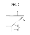
FIG. 2] Fig. 2 is a cross sectional view showing, in enlarged scale, an essential part of a further embodiment of a fastener according to the invention. - [
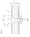
FIG. 3] Fig. 3 is a view showing a further embodiment of a fastener according to the invention and a longitudinal, cross sectional view showing an airplane assembly in a state, in which a skin and a structural material are joined by the fastener. - [
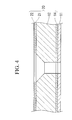
FIG. 4] Fig. 4 is a longitudinal, cross sectional view showing a skin of an airplane, to which a fastener according to the invention can be applied. -
- 1:
- fastener
- 3:
- flush head
- 5:
- insulator layer
- 10:
- skin
- 11:
- structural material
- 12:
- CFRP (resin material having conductivity)
- 15:
- conductive mesh (member having conductivity)
- A:
- airplane assembly
- An embodiment of a thunder resistant fastener according to the invention will be described below with reference to the drawings.
As shown inFig. 1 , a thunder resistant fastener 1 (referred below to as fastener) according to the embodiment comprises, as main components, afastener body 4 including a columnar-shaped shank 2 and aflush head 3 in the form of a substantially truncated cone provided on one end side of theshank 2 to increase in diameter as it goes away from theshank 2, and aninsulator layer 5 arranged to cover one end surface (upper end surface inFig. 1 ) of theflush head 3. - The
fastener body 4 is formed integrally from theshank 2 and theflush head 3 and fabricated using an alloy such as titanium (Ti-6Al-4V: annealed material), inconel, or the like.
Amale thread portion 2a being threaded into a female thread portion of a collar (nut) described later is formed at the other end (lower end inFig. 1 ) of theshank 2.
Theflush head 3 is formed to be sized so that an outside diameter D1 thereof is in the order of, for example, 2 times or more an outside diameter D2 of theshank 2. - The
insulator layer 5 is a disk-shaped member formed to be sized so that an outside diameter thereof is equal to (or substantially equal to) the outside diameter D1 of theflush head 3, and is fabricated using, for example, GFRP (glass fiber reinforced resin). Theinsulator layer 5 has a plate thickness of, for example, 1.0 mm and a sufficient dielectric strength to withstand a lightning stroke test voltage (about 40 kV) of MIL-STD-1757A Zone 1. In the case of using GFRP for theinsulator layer 5, the dielectric strength of GFRP is 40 kV/mm even when an estimate is made on the safety side, so that a sufficient dielectric strength is provided with a plate thickness of 1.0 mm even when exposed to a lightning stroke test voltage (about 40 kV) of MIL-STD-1757A Zone 1. - The fastener 1 described above is manufactured in the following procedure.
- (1) Glass cloth before curing (a pre-preg state) is laminated to be subjected to impregnation with the use of an epoxy resin, and then heated and cured to manufacture an
insulator layer 5. - (2) A
fastener body 4, of which ashank 2 is formed at the other end thereof with amale thread portion 2a is prepared and shot material particles (hard particles made of, for example, metal, ceramics, glass, or the like and having an average particle size of 200 µm or less (more specifically, at least 10 µm and at most 100 µm)) are projected on one end surface (surface) of aflush head 3 to perform a pretreatment (such treatment is referred to as shot blasting) to roughen the surface of theflush head 3.
In addition, it is possible to roughen the surface of theflush head 3 using sand paper or the like in place of shot blasting. - (3) After an adhesive (epoxy adhesive, for example, epoxy adhesive EA9396 manufactured by Hysol-Dexter Ltd.) is applied on one end surface of the
flush head 3, aninsulator layer 5 is put thereon and the adhesive is cured to fix theinsulator layer 5 to theflush head 3. - The fastener 1 manufactured in this manner is used to join, for example, a
skin 10 of an airplane shown inFig. 1 and a structural material (for example, rib, stringer, or the like) 11. In addition, theskin 10 and thestructural material 11 are joined by the fastener 1 to provide an airplane assembly (for example, wing assembly, tail assembly, fuselage assembly, or the like) A.
Theskin 10 is mainly made of a resin material (for example, CFRP (carbon fiber reinforced resin) referred below to as "CFRP") 12 having conductivity (conductivity in the order of 1/100 to 1/1000 times that of aluminum) and resin materials (for example, GFRP (glass fiber reinforced resin) referred below to as "GFRP") 13, 14 having an insulating property are laminated on a whole surface (surface positioned outside after assembling) and the whole of a back surface (surface positioned inside after assembling).
Also, a meshy (or plate-shaped) member (made of, for example, copper and referred below to as "conductive mesh") 15 being conductive as a whole is laminated on a surface (surface positioned outside after assembling) of theGFRP 13 positioned on a surface side of theCFRP 12. - The
structural material 11 is made of, for example, aluminum alloy, titanium material, or CFRP (carbon fiber reinforced resin) and arranged in a predetermined position on a back surface (the surface positioned inside after assembling) of theGFRP 14.
Recesses (holes) 16 extending through theskin 10 and thestructural material 11 and enabling receiving the fasteners 1 therein are formed in predetermined positions on a structure, of which thestructural material 11 is arranged on the back surface of theGFRP 14. The fasteners 1 are received in therespective recesses 16 and collars (nuts) 17 fabricated using, for example, titanium, inconel, or the like are clamped onto themale thread portions 2a projecting inwardly from a back surface of thestructural material 11. - Since the
insulator layer 5 is arranged on one end surface of theflush head 3 of the fastener 1 according to the embodiment, it is possible to interrupt a lightning stroke current tending to flow toward thefastener body 4 even when lightning strikes directly against theinsulator layer 5.
Also, theinsulator layer 5 is fixed to theflush head 3 through an adhesive and the fastener 1 can be manufactured readily and quickly, so that it is possible to achieve reduction in manufacturing cost.
Further, since that pretreatment, by which the surface of theflush head 3 is roughened, is applied to the surface, it is possible to surely (firmly) fix theinsulator layer 5 to theflush head 3, to surely prevent theinsulator layer 5 from peeling off theflush head 3 during the running of an airplane, and to maintain the fastener 1 in a favorable state. - Furthermore, in the case where the fastener 1 according to the embodiment is used to join, for example, the
skin 10 and the structural material (for example, rib, stringer, or the like) 11 of an airplane shown inFig. 1 , a lightning stroke current tending to flow toward thefastener body 4 is interrupted (decreased) by theinsulator layer 5, so that it is possible to prevent (decrease) conduction of the lightning stroke current to theCFRP 12, thus enabling preventing the lightning stroke current from doing damage to theCFRP 12.
Furthermore, with the fastener 1 according to the embodiment, a lightning stroke current does not flow toward thefastener body 4, so that it is possible to dispense with all DIs (Dielectric Insulator), which are conventionally needed between thestructural material 11 and thecollar 17 to prevent sparkover, and all caps made of insulating rubber and mounted to wholly cover tip ends of themale thread portions 2a and the collars 17 (mounted to prevent streamer secondarily discharged from the collars 17), thus enabling considerably decreasing an airframe weight. - In addition, the invention is not limited to the embodiment described above but PET (for example, Luminar manufactured by TORAY Ltd.) having a plate thickness of 125 µm can be adopted as an
insulator layer 5 in place of theinsulator layer 5 made of GFRP composite material.
In this manner, by using PET for theinsulator layer 5, it is possible to considerably decrease the thickness of theinsulator layer 5 and to considerably decrease the weight of one fastener.
In addition, while the dielectric breakdown voltage of GFRP is about 40 kV/mm, the dielectric breakdown voltage of PET (biaxial oriented polyethylene terephthalate) is about 300 kV/mm.
Also, in case of using Luminar manufactured by TORAY Ltd. for theinsulator layer 5, its thickness is preferably any one of 100 µm, 125 µm, 188 µm, 210 µm, and 250 µm. - Further, polyimide (kapton) having a thickness of 125 µm can be adopted for an
insulator layer 5 in place of theinsulator layer 5 made of GFRP composite material.
In this manner, by using polyimide for theinsulator layer 5, it is possible to considerably decrease the thickness of theinsulator layer 5 and to considerably decrease the weight of one fastener.
In addition, while the dielectric breakdown voltage of GFRP is about 40 kV/mm, the dielectric breakdown voltage of polyimide is about 300 kV/mm.
Also, in case of using polyimide for theinsulator layer 5, it is possible to fix the insulator layer to theflush head 3 by virtue of heat sealing with the use of a polyimide layer instead of using the epoxy adhesive (for example, epoxy adhesive EA9396 manufactured by Hysol-Dexter Ltd.) described above. - Furthermore, biaxial oriented polyethylene terephthalate (PEN) (for example, Teonex manufactured by TEIJIN Ltd.) having a plate thickness of 125 µm can be adopted for the
insulator layer 5 in place of theinsulator layer 5 made of GFRP composite material.
In this manner, by using PEN for theinsulator layer 5, it is possible to considerably decrease the thickness of theinsulator layer 5 and to considerably decrease the weight of one fastener.
In addition, while the dielectric breakdown voltage of GFRP is about 40 kV/mm, the dielectric breakdown voltage of PEN (biaxial oriented polyethylene terephthalate film) is about 300 kV/mm to 400 kV/mm.
Also, in the case of using Teonex polyimide manufactured by TEIJIN Ltd. for theinsulator layer 5, its thickness is preferably any one of 75 µm, 100 µm, 125 µm, 188 µm, and 250 µm. - Furthermore, instead of bonding (heat sealing) the
insulator layer 5 to the surface of theflush head 3, it is possible to use thermal spraying (for example, plasma thermal spraying, arc thermal spraying, HVOF thermal spraying, etc.) to form theinsulator layer 5 on the surface of theflush head 3.
Specifically, thermal spraying of alumina insulator layer onto the surface of theflush head 3 is performed.
In addition, theinsulator layer 5 is not limited to alumina and sealing with impregnation of a silicone solution and a polyimide solution is performed to enable improving the insulating property since coating with thermal spraying is poor in insulating property due to existing vacancy. - Furthermore, instead of bonding (heat sealing) the
insulator layer 5 to the surface of theflush head 3, it is possible to use the coating baking method to form theinsulator layer 5 on the surface of theflush head 3.
Specifically, a polyimide varnish (solution), for example, a polyimide varnish (U-varnish) manufactured by UBE KOUSAN Ltd. is used to coat polyimide on the surface of theflush head 3 through coating/drying/baking.
In addition, in order to increase the thickness of a polyimide layer, it suffices to repeatedly perform the processes of coating/drying/baking. - Furthermore, as shown in
Fig. 2 , it is further preferable when the outside diameter of theinsulator layer 5 is larger (larger by, for example, 1.0 mm) than the outside diameter D1 of theflush head 3.
Thereby, a lightning stroke current tending to flow toward thefastener body 4 is interrupted (decreased) by theinsulator layer 5, so that it is possible to prevent (decrease) conduction of the lightning stroke current to theCFRP 12, thus enabling preventing the lightning stroke current from doing damage to theCFRP 12. - Furthermore, as shown in
Fig. 2 , it is further preferable when asecond insulator layer 5a is provided circumferentially on a peripheral edge of theflush head 3 positioned radially outward.
Thereby, it is possible to prevent (decrease) flow of electric current due to secondary electric discharge of thunderbolt. - Furthermore, it is also possible to wet-install the
shank 2 with the use of a conductive compound. Thereby, it is possible to make sure contact between theshank 2 and theCFRP 12, thus enabling further lowering the fastener in electric potential at the time of lightning stroke (at the time of thunderbolt). - Furthermore, as shown in
Fig. 3 , it is further preferable when theinsulator layer 5 is formed (theinsulator layer 5 is set in thickness) so that the surface of theinsulator layer 5 and the surface of theconductive mesh 15 are put in a substantially flush (or flush) state.
Thereby, it is possible to put the surface of theskin 10 after coating in a further flush state, thus enabling achieving a further decrease in aerodynamic drag. - Furthermore, the fastener according to the invention is not used only to join the
skin 10 of an airplane shown inFig. 1 and the structural material (for example, rib, stringer, or the like) 11 but can be used to join, for example, askin 20 of an airplane shown inFig. 4 and thestructural material 11.
Theskin 20 is mainly made of a resin material (for example, CFRP (carbon fiber reinforced resin) referred below to as "CFRP") 12 having conductivity (conductivity in the order of 1/100 to 1/1000 times that of aluminum), a member (made of, for example, copper) 21 being conductive is laminated on a surface (surface positioned outside after assembling) of the skin, and a resin material (for example, GFRP (glass fiber reinforced resin) referred below to as "GFRP") 14 having an insulating property is laminated on a whole back surface (surface positioned inside after assembling) of the skin.
Also, a resin material (for example, GFRP (glass fiber reinforced resin)) 22 having an insulating property is laminated on a whole surface of themember 21 being conductive and positioned on a front surface of theCFRP 12.
Claims (7)
- A fastener that joins a skin of an airplane and a structural material positioned inside the skin, the fastener characterized in that one end surface of a flush head is covered by an insulator layer.
- A fastener according to claim 1, wherein the insulator layer is an insulating material that exhibits 100 kV/mm or more in terms of a value of dielectric breakdown voltage.
- A fastener according to claim 2, wherein the insulating material is composed of one of biaxial oriented polyethylene terephthalate film, polyimide film, biaxial oriented polyethylene naphthalate film, polyphenylene sulfide film, and biaxial oriented polypropylene film.
- A fastener according to any one of claims 1 to 3, wherein the insulator layer is fixed to the flush head through an adhesive.
- A fastener according to claim 1 or 2, wherein the insulator layer is formed by thermal spraying or a coating baking method.
- An airplane assembly comprising a skin, of which a main element is made of a resin material having conductivity, a structural material that supports the skin from inside, and a fastener according to any one of claims 1 to 5, and
wherein the fastener that joins the skin and the structural material comprises the fastener. - An airplane assembly according to claim 6, wherein a member having conductivity is laminated on an outer surface of the resin material having conductivity.
Applications Claiming Priority (2)
| Application Number | Priority Date | Filing Date | Title |
|---|---|---|---|
| JP2006161273 | 2006-06-09 | ||
| PCT/JP2007/061755 WO2007142354A1 (en) | 2006-06-09 | 2007-06-11 | Fastener |
Publications (3)
| Publication Number | Publication Date |
|---|---|
| EP2028100A1 true EP2028100A1 (en) | 2009-02-25 |
| EP2028100A4 EP2028100A4 (en) | 2011-08-03 |
| EP2028100B1 EP2028100B1 (en) | 2013-05-15 |
Family
ID=38801596
Family Applications (1)
| Application Number | Title | Priority Date | Filing Date |
|---|---|---|---|
| EP07745044.3A Ceased EP2028100B1 (en) | 2006-06-09 | 2007-06-11 | Fastener |
Country Status (6)
| Country | Link |
|---|---|
| US (1) | US8092134B2 (en) |
| EP (1) | EP2028100B1 (en) |
| JP (1) | JP4727727B2 (en) |
| BR (1) | BRPI0711444B1 (en) |
| CA (1) | CA2653134C (en) |
| WO (1) | WO2007142354A1 (en) |
Cited By (1)
| Publication number | Priority date | Publication date | Assignee | Title |
|---|---|---|---|---|
| WO2018142108A1 (en) * | 2017-02-06 | 2018-08-09 | Short Brothers Plc | Aircraft electrical isolation component and method of manufacturing electrical isolation component |
Families Citing this family (16)
| Publication number | Priority date | Publication date | Assignee | Title |
|---|---|---|---|---|
| DE102007003276B4 (en) | 2007-01-23 | 2013-11-28 | Airbus Operations Gmbh | Aerospace vehicle with a CFRP component and a metal component, wherein the CFRP component and the metal component are connected to each other via at least one connecting element with a connecting portion |
| JP5040739B2 (en) * | 2008-03-10 | 2012-10-03 | トヨタ自動車株式会社 | Split stator member, split stator member manufacturing method, and stator |
| BRPI1006600B1 (en) | 2009-04-17 | 2019-10-08 | 3M Innovative Properties Company | ATMOSPHERIC DISCHARGE PROTECTION COATING |
| CA2758798C (en) | 2009-04-17 | 2019-04-23 | 3M Innovative Properties Company | Lightning protection sheet with patterned discriminator |
| US8800241B2 (en) | 2012-03-21 | 2014-08-12 | Mitek Holdings, Inc. | Backup wall reinforcement with T-type anchor |
| JP5713980B2 (en) * | 2012-10-15 | 2015-05-07 | 三菱航空機株式会社 | Lightning-resistant fasteners and aircraft |
| US9038351B2 (en) | 2013-03-06 | 2015-05-26 | Columbia Insurance Company | Thermally coated wall anchor and anchoring systems with in-cavity thermal breaks for cavity walls |
| US8863460B2 (en) | 2013-03-08 | 2014-10-21 | Columbia Insurance Company | Thermally coated wall anchor and anchoring systems with in-cavity thermal breaks |
| US9140001B1 (en) * | 2014-06-24 | 2015-09-22 | Columbia Insurance Company | Thermal wall anchor |
| EP3249242B1 (en) * | 2015-01-22 | 2019-10-09 | Nissan Motor Co., Ltd. | Fastening structure for carbon fiber-reinforced resin material |
| US9273461B1 (en) | 2015-02-23 | 2016-03-01 | Columbia Insurance Company | Thermal veneer tie and anchoring system |
| USD846973S1 (en) | 2015-09-17 | 2019-04-30 | Columbia Insurance Company | High-strength partition top anchor |
| US10407892B2 (en) | 2015-09-17 | 2019-09-10 | Columbia Insurance Company | High-strength partition top anchor and anchoring system utilizing the same |
| US20170159285A1 (en) | 2015-12-04 | 2017-06-08 | Columbia Insurance Company | Thermal wall anchor |
| EP3231713A1 (en) * | 2016-04-13 | 2017-10-18 | Airbus Operations GmbH | Fastener system for ignition prevention triggered by a lightning strike, structure comprising the fastener system, and method for manufacturing the structure |
| US20240017685A1 (en) * | 2022-07-18 | 2024-01-18 | J. & P. Coats, Limited | Vehicle component based on selective commingled fiber bundle having integral electrical harness and embedded electronics |
Family Cites Families (24)
| Publication number | Priority date | Publication date | Assignee | Title |
|---|---|---|---|---|
| US3122051A (en) * | 1961-01-24 | 1964-02-25 | Greene Samuel | Ornamental protective covering for removable fasteners |
| JPS5454771U (en) * | 1977-09-27 | 1979-04-16 | ||
| JPS5454771A (en) | 1977-10-08 | 1979-05-01 | Minoru Negoro | Finely fragmental cutting blade |
| US4502092A (en) * | 1982-09-30 | 1985-02-26 | The Boeing Company | Integral lightning protection system for composite aircraft skins |
| US4479163A (en) * | 1982-09-30 | 1984-10-23 | The Boeing Company | Integral lightning protection system for composite aircraft skins |
| US4628402A (en) * | 1985-09-30 | 1986-12-09 | The Boeing Company | Lightning protection of fasteners in composite material |
| US4760493A (en) * | 1985-09-30 | 1988-07-26 | The Boeing Company | Lightning protection system for composite material aircraft structures |
| US4630168A (en) * | 1985-12-16 | 1986-12-16 | The Boeing Company | Lightning protection fastener |
| JP2612276B2 (en) | 1986-07-25 | 1997-05-21 | 旭化成工業株式会社 | Aramid film for electrical insulation |
| ZA875318B (en) | 1986-08-28 | 1988-01-25 | Warner-Lambert Company | Enzyme containing denture cleansers and method of use |
| JPS63130909A (en) * | 1986-11-10 | 1988-06-03 | マイクロドツト インコ−ポレ−テツド | Capsule fixture |
| JPS63101313U (en) * | 1986-12-22 | 1988-07-01 | ||
| US4979281A (en) * | 1987-12-21 | 1990-12-25 | Lockheed Corporation | Method of installing a flush head fastener |
| JPH0547850Y2 (en) * | 1988-02-27 | 1993-12-17 | ||
| JPH0318045A (en) | 1989-06-14 | 1991-01-25 | Matsushita Electron Corp | Semiconductor device |
| GB9411006D0 (en) * | 1994-06-02 | 1994-07-20 | British Aerospace | Method of fastening composite aircraft skins |
| US6302630B1 (en) * | 2000-04-18 | 2001-10-16 | Lockheed Martin | Fastener with recessed head and head insert |
| JP4067858B2 (en) | 2002-04-16 | 2008-03-26 | 東京エレクトロン株式会社 | ALD film forming apparatus and ALD film forming method |
| JP2004107658A (en) | 2002-08-28 | 2004-04-08 | Du Pont Toray Co Ltd | Polyimide film and method for producing the same |
| EP1628879B1 (en) * | 2003-05-30 | 2006-09-20 | BAE Systems PLC | Composite structure lightning protection |
| JP4831939B2 (en) | 2004-03-31 | 2011-12-07 | アイファイヤー アイピー コーポレイション | Luminescent thin film and light emitting element |
| JP4786426B2 (en) * | 2005-10-06 | 2011-10-05 | 三菱重工業株式会社 | Fastener |
| US7277266B1 (en) * | 2006-03-29 | 2007-10-02 | The Boeing Company | Lightning protection system for composite structure |
| JP4719203B2 (en) | 2007-09-28 | 2011-07-06 | 三菱重工業株式会社 | Lightning fastener |
-
2007
- 2007-06-11 EP EP07745044.3A patent/EP2028100B1/en not_active Ceased
- 2007-06-11 US US12/227,642 patent/US8092134B2/en active Active
- 2007-06-11 JP JP2008520649A patent/JP4727727B2/en not_active Expired - Fee Related
- 2007-06-11 WO PCT/JP2007/061755 patent/WO2007142354A1/en not_active Ceased
- 2007-06-11 BR BRPI0711444A patent/BRPI0711444B1/en not_active IP Right Cessation
- 2007-06-11 CA CA2653134A patent/CA2653134C/en not_active Expired - Fee Related
Cited By (2)
| Publication number | Priority date | Publication date | Assignee | Title |
|---|---|---|---|---|
| WO2018142108A1 (en) * | 2017-02-06 | 2018-08-09 | Short Brothers Plc | Aircraft electrical isolation component and method of manufacturing electrical isolation component |
| US11472569B2 (en) | 2017-02-06 | 2022-10-18 | Short Brothers Plc | Aircraft electrical isolation component and method of manufacturing electrical isolation component |
Also Published As
| Publication number | Publication date |
|---|---|
| BRPI0711444A2 (en) | 2011-11-01 |
| CA2653134C (en) | 2012-02-07 |
| EP2028100A4 (en) | 2011-08-03 |
| BRPI0711444B1 (en) | 2020-04-28 |
| JPWO2007142354A1 (en) | 2009-10-29 |
| JP4727727B2 (en) | 2011-07-20 |
| US8092134B2 (en) | 2012-01-10 |
| CA2653134A1 (en) | 2007-12-13 |
| US20090173828A1 (en) | 2009-07-09 |
| WO2007142354A1 (en) | 2007-12-13 |
| EP2028100B1 (en) | 2013-05-15 |
Similar Documents
| Publication | Publication Date | Title |
|---|---|---|
| CA2653134C (en) | Fastener | |
| JP4786426B2 (en) | Fastener | |
| US8711541B2 (en) | Lightning-protective explosion-preventive fastener | |
| US9702255B2 (en) | Propeller with lightening strike protection | |
| EP2147855A1 (en) | Aircraft assembly and method for manufacturing the same | |
| JP5055178B2 (en) | Aircraft assembly | |
| EP2947015B1 (en) | Modified shank fasteners for electromagnetic effect (eme) technology | |
| US9669942B2 (en) | Lightning damage resistant aircraft skin fasteners | |
| EP2184227B1 (en) | Lighting-resisting fastener | |
| EP2402248B1 (en) | Improvement of the protection against direct lightning strikes in riveted areas of cfrp panels | |
| US8462481B2 (en) | Lightning protection system and aircraft comprising such a system | |
| RU2592958C2 (en) | Fastening systems, ensuring protection against electromagnetic effects | |
| GB2212580A (en) | Anti-lightning fastener | |
| CN107521653B (en) | Lightning strike dispersion for composite aircraft structures | |
| CN110319098B (en) | Electromagnetic effect shielding fastener with frangible collar | |
| EP3992479B1 (en) | Spark containment cap | |
| US20240009961A1 (en) | Structure with lightning-strike protection layer | |
| US20180079527A1 (en) | Structure manufacturing device and structure manufacturing method |
Legal Events
| Date | Code | Title | Description |
|---|---|---|---|
| PUAI | Public reference made under article 153(3) epc to a published international application that has entered the european phase |
Free format text: ORIGINAL CODE: 0009012 |
|
| 17P | Request for examination filed |
Effective date: 20081201 |
|
| AK | Designated contracting states |
Kind code of ref document: A1 Designated state(s): AT BE BG CH CY CZ DE DK EE ES FI FR GB GR HU IE IS IT LI LT LU LV MC MT NL PL PT RO SE SI SK TR |
|
| AX | Request for extension of the european patent |
Extension state: AL BA HR MK RS |
|
| DAX | Request for extension of the european patent (deleted) | ||
| RBV | Designated contracting states (corrected) |
Designated state(s): DE FR GB |
|
| A4 | Supplementary search report drawn up and despatched |
Effective date: 20110704 |
|
| RIC1 | Information provided on ipc code assigned before grant |
Ipc: F16B 33/06 20060101ALI20110628BHEP Ipc: F16B 35/00 20060101ALI20110628BHEP Ipc: B64D 45/02 20060101ALI20110628BHEP Ipc: B29C 65/48 20060101ALI20110628BHEP Ipc: B64C 1/00 20060101AFI20110628BHEP |
|
| GRAP | Despatch of communication of intention to grant a patent |
Free format text: ORIGINAL CODE: EPIDOSNIGR1 |
|
| GRAS | Grant fee paid |
Free format text: ORIGINAL CODE: EPIDOSNIGR3 |
|
| GRAP | Despatch of communication of intention to grant a patent |
Free format text: ORIGINAL CODE: EPIDOSNIGR1 |
|
| GRAA | (expected) grant |
Free format text: ORIGINAL CODE: 0009210 |
|
| AK | Designated contracting states |
Kind code of ref document: B1 Designated state(s): DE FR GB |
|
| REG | Reference to a national code |
Ref country code: GB Ref legal event code: FG4D |
|
| REG | Reference to a national code |
Ref country code: DE Ref legal event code: R096 Ref document number: 602007030462 Country of ref document: DE Effective date: 20130711 |
|
| PLBE | No opposition filed within time limit |
Free format text: ORIGINAL CODE: 0009261 |
|
| STAA | Information on the status of an ep patent application or granted ep patent |
Free format text: STATUS: NO OPPOSITION FILED WITHIN TIME LIMIT |
|
| 26N | No opposition filed |
Effective date: 20140218 |
|
| REG | Reference to a national code |
Ref country code: DE Ref legal event code: R097 Ref document number: 602007030462 Country of ref document: DE Effective date: 20140218 |
|
| REG | Reference to a national code |
Ref country code: FR Ref legal event code: PLFP Year of fee payment: 10 |
|
| REG | Reference to a national code |
Ref country code: FR Ref legal event code: PLFP Year of fee payment: 11 |
|
| REG | Reference to a national code |
Ref country code: FR Ref legal event code: PLFP Year of fee payment: 12 |
|
| PGFP | Annual fee paid to national office [announced via postgrant information from national office to epo] |
Ref country code: DE Payment date: 20210518 Year of fee payment: 15 Ref country code: FR Payment date: 20210513 Year of fee payment: 15 |
|
| PGFP | Annual fee paid to national office [announced via postgrant information from national office to epo] |
Ref country code: GB Payment date: 20210519 Year of fee payment: 15 |
|
| REG | Reference to a national code |
Ref country code: DE Ref legal event code: R119 Ref document number: 602007030462 Country of ref document: DE |
|
| GBPC | Gb: european patent ceased through non-payment of renewal fee |
Effective date: 20220611 |
|
| PG25 | Lapsed in a contracting state [announced via postgrant information from national office to epo] |
Ref country code: FR Free format text: LAPSE BECAUSE OF NON-PAYMENT OF DUE FEES Effective date: 20220630 |
|
| PG25 | Lapsed in a contracting state [announced via postgrant information from national office to epo] |
Ref country code: GB Free format text: LAPSE BECAUSE OF NON-PAYMENT OF DUE FEES Effective date: 20220611 Ref country code: DE Free format text: LAPSE BECAUSE OF NON-PAYMENT OF DUE FEES Effective date: 20230103 |