EP2028009A1 - Liquid Droplet Flight Device and Image Forming Apparatus - Google Patents
Liquid Droplet Flight Device and Image Forming Apparatus Download PDFInfo
- Publication number
- EP2028009A1 EP2028009A1 EP08162738A EP08162738A EP2028009A1 EP 2028009 A1 EP2028009 A1 EP 2028009A1 EP 08162738 A EP08162738 A EP 08162738A EP 08162738 A EP08162738 A EP 08162738A EP 2028009 A1 EP2028009 A1 EP 2028009A1
- Authority
- EP
- European Patent Office
- Prior art keywords
- flight
- liquid
- electrode
- liquid droplet
- ink
- Prior art date
- Legal status (The legal status is an assumption and is not a legal conclusion. Google has not performed a legal analysis and makes no representation as to the accuracy of the status listed.)
- Granted
Links
Images


Classifications
-
- B—PERFORMING OPERATIONS; TRANSPORTING
- B41—PRINTING; LINING MACHINES; TYPEWRITERS; STAMPS
- B41J—TYPEWRITERS; SELECTIVE PRINTING MECHANISMS, i.e. MECHANISMS PRINTING OTHERWISE THAN FROM A FORME; CORRECTION OF TYPOGRAPHICAL ERRORS
- B41J2/00—Typewriters or selective printing mechanisms characterised by the printing or marking process for which they are designed
- B41J2/005—Typewriters or selective printing mechanisms characterised by the printing or marking process for which they are designed characterised by bringing liquid or particles selectively into contact with a printing material
- B41J2/01—Ink jet
- B41J2/015—Ink jet characterised by the jet generation process
- B41J2/04—Ink jet characterised by the jet generation process generating single droplets or particles on demand
- B41J2/06—Ink jet characterised by the jet generation process generating single droplets or particles on demand by electric or magnetic field
-
- B—PERFORMING OPERATIONS; TRANSPORTING
- B41—PRINTING; LINING MACHINES; TYPEWRITERS; STAMPS
- B41J—TYPEWRITERS; SELECTIVE PRINTING MECHANISMS, i.e. MECHANISMS PRINTING OTHERWISE THAN FROM A FORME; CORRECTION OF TYPOGRAPHICAL ERRORS
- B41J2/00—Typewriters or selective printing mechanisms characterised by the printing or marking process for which they are designed
- B41J2/005—Typewriters or selective printing mechanisms characterised by the printing or marking process for which they are designed characterised by bringing liquid or particles selectively into contact with a printing material
- B41J2/01—Ink jet
- B41J2/135—Nozzles
- B41J2/145—Arrangement thereof
- B41J2/15—Arrangement thereof for serial printing
-
- B—PERFORMING OPERATIONS; TRANSPORTING
- B41—PRINTING; LINING MACHINES; TYPEWRITERS; STAMPS
- B41J—TYPEWRITERS; SELECTIVE PRINTING MECHANISMS, i.e. MECHANISMS PRINTING OTHERWISE THAN FROM A FORME; CORRECTION OF TYPOGRAPHICAL ERRORS
- B41J2/00—Typewriters or selective printing mechanisms characterised by the printing or marking process for which they are designed
- B41J2/005—Typewriters or selective printing mechanisms characterised by the printing or marking process for which they are designed characterised by bringing liquid or particles selectively into contact with a printing material
- B41J2/01—Ink jet
- B41J2/135—Nozzles
- B41J2/14—Structure thereof only for on-demand ink jet heads
- B41J2002/14395—Electrowetting
-
- B—PERFORMING OPERATIONS; TRANSPORTING
- B41—PRINTING; LINING MACHINES; TYPEWRITERS; STAMPS
- B41J—TYPEWRITERS; SELECTIVE PRINTING MECHANISMS, i.e. MECHANISMS PRINTING OTHERWISE THAN FROM A FORME; CORRECTION OF TYPOGRAPHICAL ERRORS
- B41J2/00—Typewriters or selective printing mechanisms characterised by the printing or marking process for which they are designed
- B41J2/005—Typewriters or selective printing mechanisms characterised by the printing or marking process for which they are designed characterised by bringing liquid or particles selectively into contact with a printing material
- B41J2/01—Ink jet
- B41J2/135—Nozzles
- B41J2/14—Structure thereof only for on-demand ink jet heads
- B41J2002/14459—Matrix arrangement of the pressure chambers
Definitions
- the present invention relates to liquid droplet flight devices and liquid droplet flight methods that are used in image forming apparatuses such as copiers, printer apparatuses, and facsimile machines to induce flight of liquid droplet such as ink liquid droplets, and particularly relates liquid droplet flight devices and liquid droplet flight methods capable of stably forming high image quality images by causing stable flight of liquid droplets using an electrostatic attraction method.
- H11-198381 (referred to as Prior Art 1) is provided, with a plurality of electrodes arranged on an ink discharge outlet side and an opposing electrode arranged in a position in opposition to leading end portions of these electrodes, and a high voltage of 1800 V for example is applied to electrodes arranged in positions near electrodes that are to form an ink discharge point at which ink is to be discharged in order to eliminate flight of ink from unintended electrodes, thereby lowering the electric potential of ink discharge points below that of electrodes arranged in nearby positions and reducing the ink at the leading ends of nearby electrodes at which ink has accumulated at the ink discharge points such that a discharge meniscus forms at the ink discharge points and ink liquid droplets are caused to fly from electrodes at the ink discharge points.
- Prior Art 2 discloses a hyperfine liquid jet apparatus in which ink liquid droplets are discharged using an electrostatic attraction method and an electrowetting effect.
- the hyperfine liquid jet apparatus shown in Prior Art 2 is configured such that a flight electrode is provided inside hyperfine diameter nozzles that supply a liquid, and an electrode that covers a leading end outer side is provided outside the hyperfine diameter nozzles, and a substrate constituted by an opposing electrode is arranged at a distance of 0. 05. mm or less from the leading ends of the hyperfine diameter nozzles.
- the liquid inside the hyperfine diameter nozzles moves to the opposing electrode side, and liquid droplets are caused to fly by locally increasing the strength of an electric field.
- Prior Art 1 requires a pulse drive device to apply a high voltage pulse voltage in order to discharge ink, which is disadvantageous in that it involves high costs and offers poor frequency responsiveness.
- the hyperfine liquid jet apparatus shown in Prior Art 2 requires a comparatively high voltage of approximately 300 V so to be capable of creating a capillary phenomenon and to achieve resistance to enable the electrowetting effect. Furthermore, this is difficult to apply to high viscosity inks.
- a liquid droplet flight, device comprises a liquid droplet discharge device; and an opposing electrode arranged opposite to the liquid droplet discharge device.
- the liquid droplet discharge device is provided with a liquid retaining section having a liquid holding section that holds a liquid to be caused to fly, and a flight device that causes the liquid held in the liquid holding section to fly.
- the flight device is provided with a needle-shaped flight electrode arranged inside the liquid holding section, an electric field generating device for generating an electric field between the flight electrode and the opposing electrode, an electrowetting drive electrode (EW drive electrode) arranged inside the liquid holding section, and a flight control device for moving the liquid of the liquid holding section to the electric field generated by the flight electrode of the electric field generating device using an electrowetting phenomenon, by applying a voltage between the EW drive electrode and the liquid inside the liquid retaining section.
- EW drive electrode electrowetting drive electrode
- a low voltage is applied between the EW drive electrode and the liquid inside the liquid retaining section by the flight control device while a high voltage is applied between the flight electrode and the opposing electrode by the electric field generating device, in order to cause a liquid droplet to fly onto a medium arranged between the liquid droplet, discharge device and the opposing electrode.
- the liquid droplet discharge means is an ink droplet discharge means and the liquid holding section is an ink holding section.
- the flight electrode and the electrowetting drive electrode respectively comprise one or more electrodes.
- an image forming apparatus is provided with an ink droplet flight device that discharges ink droplets onto a recording medium transported on a transport path, in order to record text or images.
- the ink droplet flight device comprises an ink droplet discharge device and an opposing electrode arranged opposite to the ink droplet discharge device.
- the ink droplet discharge device is provided with an ink retaining section having an ink holding section in a slit shape or a plurality of one-dimenslonally arranged pass-through holes that hold ink to be caused to fly, and a flight device for causing the ink held in the ink holding section to fly.
- the flight device is provided with a plurality of flight electrodes formed in a needle shape, arranged in a comb teeth manner inside the ink holding section; an electric field generating device that generates an electric field between the plurality of flight electrodes and the opposing electrode; a plurality of electrowetting drive electrodes (EW drive electrodes) arranged inside the ink holding section, corresponding to the flight electrodes; and a flight control device that moves the ink of the ink holding section to the electric field generated by the flight electrodes of the electric field generating device using an electrowetting phenomenon, by applying a voltage between the EW drive electrodes and the ink near each of the flight electrodes inside the ink retaining section.
- EW drive electrodes electrowetting drive electrodes
- a pulse-form low voltage is applied between the EW drive electrodes and the ink near each of the flight, electrodes inside the ink retaining section by the flight control device while a high voltage is applied between the flight electrodes and the opposing electrode by the electric field generating device, in order to cause ink droplets to fly onto a recording medium transported between the ink droplet discharge device and the opposing electrode.
- FIG. 1 shown a configuration of a liquid droplet flight device according to the present invention.
- a liquid droplet flight device 1 is provided with a liquid droplet discharge means 2, and an opposing electrode 3 arranged in opposition to the liquid droplet discharge means 2,
- the liquid droplet discharge means 2 is provided with a liquid retaining section 4 and a flight means 5.
- the liquid retaining section 4 is provided with a slit or a pass-through hole (hereinafter referred to as "slit") 6 and is formed with a material having insulating properties.
- slit a pass-through hole
- the flight means 5 is provided with a rod-shaped flight electrode 7, an insulating film 8 arranged on an outer circumferential surface of the flight electrode 7, an electrowetting drive electrode (hereinafter, referred to as "EW drive electrode") 9 arranged on an outer circumferential surface of the insulating film 8, an insulating film 10 that covers an outer circumferential surface of the EW drive electrode 9, and a water-repellent film 11 arranged on an outer circumferential surface of the insulating film 10, and a leading edge portion thereof is arranged inside the slit 6 so as to protrude slightly from the slit 6 of the liquid retaining section 4.
- a liquid-absorbing material such as a sponge for example may also be provided in the slit 6.
- the flight electrode 7 is a material having conductive properties and anti-discharge properties, for example, copper and tungsten, or a carbon or the like, and is formed having an outer diameter of 0.005 to 0.03 mm, for example, 0.015 mm.
- the EW drive electrode 9 is a material having good conductive properties, for example, copper and tungsten, or a carbon for the like, and is formed having a thickness of 0.001 to 0.005 mm, for example, 0.001 mm.
- the flight electrode 7 and the EW drive electrode 9 are formed using an etching or spattering method, or a CVD method.
- the insulating film 8 and the insulating film 10 are materials having good insulating properties and anti-discharge properties, for example, SiO 2 , and are formed having a thickness of 0.001 to 0.005 mm, for example, 0.001 mm.
- the water-repellent film 11 is formed with a fluorine-based resin for example.
- a high-viscosity liquid 12 having insulating properties for example an ink having a viscosity of 8 mPa ⁇ s or more, is retained in the liquid retaining section 4, and the width of the slit 6 is determined in accordance with an outer diameter of the flight electrode 7, and in a case where the outer diameter of the flight electrode 7 is 0.015 mm, and for example is formed to approximately 0.2 mm so as to be capable of ensuring a flow channel cross-sectional area sufficient for replenishing ink that has flown.
- the opposing electrode 3 is formed with a material having good conductive properties, copper for example, and is arranged leaving a space of 0.01 to 0.5 mm from the leading edge of the flight electrode 7, for example 0.2 mm.
- the flight electrode 7 is connected to the opposing electrode 3 via a bias power source 13, and a high voltage bias voltage of approximately 2 kV for example is applied to it from the bias power source 13.
- the EW drive electrode 9 is connected to the liquid 12 of the liquid retaining section 4 via a drive power source 14 and a fright control means 15, and a low voltage drive voltage of 100 V or less is applied to it.
- the bias power source 13, the drive power source 14, and the flight control means 15 are controlled by a control device 16 as shown in the block diagram of FIG. 3 .
- the liquid droplet discharge means is an ink droplet discharge means and the liquid holding section is an ink holding section.
- the flight electrode and the electrowetting drive electrode respectively comprise one or more electrodes.
- the control device 16 applies a high voltage to the flight electrode 7 from the bias power source 13 such that an electric field 18 is produced between the flight electrode 7 and the opposing electrode 3 as shown in FIG. 1 .
- a slit 6 side surface of the liquid 12 inside the slit 6 of the liquid retaining section 4 is positioned inside the slit 6, which is outside an electric field 18of the flight electrode 7 due to a meniscus produced due a water-repellent effect of the water-repellent film 11 of the flight means 5.
- control device 16 performs on/off control on the flight control means 15 and applies a low voltage drive voltage to the EW drive electrode 9 from the drive power source 14.
- the drive voltage is applied to the EW derive electrode 9, the liquid 12 inside the slit 6 moves to the leading edge portion of the flight electrode 7 as shown in FIG. 4 due to an electrowetting phenomenon.
- a high viscosity liquid 12 can be caused to fly stably.
- the image forming apparatus is provided with a one-dimensional discharge unit 20 in which a plurality of flight means 5a to 5n are arranged in a comb teeth manner at an image resolution pitch in the liquid retaining section 4 of the slit 6 of the liquid droplet flight device 1.
- the opposing electrode 3 is arranged in opposition to the leading edge portions of the pointed flight electrodes 7 of the flight means 3a to 5n, and a recording paper 17 is supplied that is transported by a transport belt 68 between the flight electrodes 7 and the opposing electrode 3.
- flight electrodes 7 of the flight means 5a to 5n are connected to the bias power source 13, and the EW drive electrodes 9 are connected to the drive power source 14 via respective flight control sections 15a to 15n, such that ink 12 is charged near where the corresponding flight electrodes 7 are arranged.
- Trailing edge portions, which are not arranged in the liquid retaining section 4, of the flight electrodes 7 of the plurality of flight means 5a to 5n are integrally linked. These linked flight electrodes 7 may be formed using etching to have uniform microscopic intervals.
- an image forming apparatus 51 provided with the one-dimensional discharge unit 20 is provided with a paper supply tray 52, which is mounted on the apparatus main unit and accommodates recording papers, and a paper discharge tray 53, which is mounted on the apparatus main unit and stacks recording papers on which images have been recorded.
- An openable/closeable upper cover 54 is provided on an upper side of the apparatus main unit.
- a cartridge loading section 56 is provided at one end portion of a front surface 55 of the apparatus main unit protruding forwardly and at a lower position than the upper cover 54, and an operation section 57 including operation keys and a display device and the like is provided above the cartridge loading section 56.
- An opcnable/closeable front cover 58 is provided at a front surface of the cartridge loading section 56 and by opening the front cover 58, ink cartridges 59, which are the main tanks for replenishing ink, can be removed and attached.
- the mechanical portion of the image forming apparatus 51 may use either a carriage movement method or a line head method.
- the mechanical portion of a carriage movement method involves a carriage 63 being slidably supported in a main scanning direction by a guide rod 61, which is a guiding member extending laterally between side panels of the apparatus main unit 51, and a stay 62, and being moved and scanned in a carriage main scanning direction by a main scanning motor.
- sub tanks 64 are mounted in the carriage 63, which are liquid containers of each color for supplying ink of each of the colors to the one-dimensional discharge units 20. Ink is replenished and supplied to the sub tanks 64 from each the ink cartridges 59. As shown in the lateral structural diagram of FIG. 8A and the top view structural diagram of FIG.
- the mechanical portion of a line head method involves a single or multiple one-dimensional discharge units 20 having a width corresponding to the paper width of the recording paper 17 being arranged in an array in a head holder 631 to perform printing while the recording paper 17 is moved at a constant velocity.
- a crescent shaped roller (paper supply roller) 66 which separates and feeds the recording papers 17 sheet by sheet from a paper loading section 65, and a separating pad 67, which faces the paper supply roller 66, is constituted by a material having a large friction coefficient, and applies bias toward the paper supply roller 66, are provided as a paper supply section for supplying the recording papers 17 loaded on the paper loading section (pressing board) 65 of the paper supply tray 52.
- a transport belt 69 for transporting the recording papers 17 for transporting the recording papers 17, a counter roller 70 for transporting the recording papers 17 sent via the guide 67 from the paper supply section sandwiched against the transport belt 69, a transport guide 71 for performing direction conversion of approximately 90 degrees on the recording paper 17 that has been sent substantially vertically to align with the transport belt 69, and a leading edge pressure roller 73 that biases the transport belt 69 using a pressing member 72.
- an opposing electrode 3 that is in opposition to each of the flight means 5 of the one-dimensional ink discharge units 20 is arranged at a rear side of the transport belt 69.
- the transport belt 69 is an endless belt and is constructed so as to rotate around and span between a transport roller 74 and a tension roller 75.
- the transport belt 69 has a two layer structure, and the inner side thereof may have a metal conductive member such as nickel. Furthermore, when a high voltage is applied from the transport roller 74 to the conductive member of the transport belt 69, this may be used instead of the opposing electrode 3.
- a separating claw 76 for separating the recording paper 17 from the transport belt 69, a discharge roller 77, and a discharge small roller 78 are provided as a discharge section for discharging the recording papers 17 that have been recorded on by the one-dimensional discharge units 20, and a paper discharge tray 53 is provided under the discharge roller 77.
- a double-side paper supply unit 79 is attachably mounted at a rear surface portion of the apparatus main unit 51. The double-side paper supply unit 79 rotates in a reverse direction to the transport belt 69 to take in and turn over the recording paper 17 that has been returned and resend it to the transport belt 59.
- a manual paper feeding section 80 is arranged on an upper surface of the double-side paper supply unit 79.
- the drive voltages applied to the EW drive electrodes 9 of the flight means 5a to 5n of the one-dimensional discharge unit 20 are turned on and off by their respective flight control sections 15a to 15n in response to the image data to be printed, thereby causing ink droplets 12a to fly due to the electric field produced by the predetermined flight electrodes 7 such that [the ink droplets] land and are recorded on the recording paper 17 an shown in FIG. 5A .
- the speed of operation when causing the ink droplets 12a to fly depends on the speed the ink 12 moves to leading end portions of the flight electrodes 7 due to the electrowetting phenomenon when the drive voltages are applied to the EW drive electrodes 9.
- the movement speed of the ink 12 varies depending on the viscosity of the ink 12, but in a case where 0.1 msec is required to move 100 ⁇ m for example, the corresponding printing speed is 120 ppm, thus allowing high speeds to be achieved.
- the one-dimensional discharge unit 20 is configured in this manner with a liquid retaining section 4 having a slit 6 and a plurality of flight means 5a to 5n, it is possible to achieve a simple structure that is compact and lightweight, and it is also possible to improve reliability and durability since a movable drive section and a heating section are not required.
- liquid retaining section 4 is used jointly among the plurality of flight means 5a to 5n to form the ink flow channel including the slit 6 of the liquid retaining section 4, high viscosity inks can be stably supplied into the slit 6 and it is possible to achieve greater speeds in printing and higher image quality.
- the liquid retaining section 4 can be used as the ink flow channel and high viscosity inks can be stably and continuously supplied, thereby enabling greater speeds in printing to be achieved.
- the recording paper 17 is transported while drive voltages are applied by flight control sections 15ij to EW drive electrodes 9 of a plurality of flight means 5ij in response to image data to achieve flash printing, thereby enabling even greater printing speeds to be achieved.
- the transport speed of the recording paper 17 is 1 m/sec
- the corresponding printing speed is 286 ppm, enabling printing to be performed at high speed.
- the speed of the ink 12 becomes slower in moving to the leading end portion of the flight electrode 7 due to the electrowetting phenomenon when the drive voltage is applied to the EW drive electrode 9.
- the ink droplets 12a fly due to the electric field produced by the flight electrode 7 when the ink 12 moves to the leading end portion of the flight electrode 7 due to the electrowetting phenomenon by the inputting of a pixel signal to the drive voltage to the EW drive electrode 9 as shown in the waveform diagram of FIG.
- the two-dimensional discharge unit 21 on a transport path on which the recording paper 17 is transported by a pair of transport rollers 741 and a pair of tension rollers 751 arranged before and after a recording region as shown in the lateral configuration diagram of the structural sections of the image forming apparatus 51 in FIG. 11A , and using the opposing electrode 3 that faces the two-dimensional discharge unit 21 as a transport guide, it is possible to print an image on the recording paper 17 at high speed. Furthermore, by arranging the two-dimensional discharge unit 21 on the transport path of a roll shaped recording paper 17 as shown in FIG. 11B , or, as shown in FIG.
- the recording paper 17 can be printed continuously on both sides, thereby enabling improved printing efficiency. Further still, by alternately arranging the two-dimensional discharge units 21Y, 21C, 21M, and 21Bk of the colors yellow (Y), cyan (C), magenta (M), and black (Bk) on the front side and the rear side of the transport path of the recording paper 17, it is possible to ensure a drying time for the ink that has flown onto the recording paper 17.
- the flight means 5 of the liquid droplet discharge means 2 was provided independent from the liquid retaining section 4, but as shown in the cross-sectional views of FIG. 14A and 14B , the flight means 5 may be arranged along a wall surface 4a that forms the slit 6 of the liquid retaining section 4 such that the flight means 5 is integrated with one side of the wall surface 4a of the liquid retaining section 4.
- the EW drive electrode 9 is provided in a region of half of an outer circumferential surface of the insulating film 8 that covers an outer circumferential surface of the flight electrode 7, and an outer circumferential surface of the EW drive electrode 9 is covered by the insulating film 10 and the water-repellent film 11, then a region of the insulating film 8 covering the outer circumferential surface of the flight electrode 7 where the EW drive electrode 9 is not provided is secured along the wall surface 4a of the side where the slit 6 of the liquid retaining section 4 is formed.
- the flight means 5 By providing the flight means 5 in this manner along the wall surface 4a of the side where the slit 6 of the liquid retaining section 4 is formed, the flight means 5 can be held stably, and the flight means 5 can be held simply.
- FIG. 14A shows a case where the flight electrode 7 is entirely aligned with the wall surface 4a where the slit 6 of the liquid retaining section 4 is formed
- FIG. 14B shows a case where the leading end portion of the flight electrode 7 that produces the electric field is apart by a fixed interval from the wall surface 4a where the slit 6 of the liquid retaining section 4 is formed.
- FIG. 14B by setting apart the leading end portion of the flight electrode 7 that produces the electric field from the wall surface 4a, the electric field that is produced can be better stabilized.
- the flight electrode 7 may be arranged inside the slit 6 of the liquid retaining section 4 with outer circumferential surfaces thereof covered by the water-repellent film 11, and the EW drive electrodes 9 may be provided in portions corresponding to the flight electrode 7 at both wall surfaces 4a and 4b where the slit 6 of the liquid retaining section 4 is formed.
- the outer circumferential surfaces of the EW drive electrodes 9 may be covered by the insulating film 10 and [areas] other than attachment surfaces of the insulating film 10 to the wall surfaces 4a and 4b may be covered by the water-repellent film 11.
- the ink 12 can be moved very efficiently to the leading end portion of the flight electrode 7 using the electrowetting phenomenon and printing speeds can be further increased.
- the electric field produced by the flight electrodes 7 can be further stabilized and the ink 12 moved by the electrowetting phenomenon can be moved easily to the leading end portion of the flight electrode 7, thereby enabling further increased printing speeds to be achieved.
- the EW drive electrode 9 may be formed integrally with the flight electrode 7 as shown in FIG. 18 and the water-repellent film 11 may also be provided on both wall surfaces 4a and 4b forming the slit 6 of the liquid retaining section 4.
- a rod shaped flight electrode 7 was provided in the flight means 5 of the liquid droplet flight device 1, which caused the ink droplets 12a to fly using the one-dimensional discharge unit 20 or the two-dimensional discharge unit 21 in which ink droplets 12a of the image forming apparatus were caused to fly, but as shown in FIG. 20A , the leading end portion that is arranged inside the slit 6 of the liquid retaining section 4 of the flight electrode 7 may be formed into a flat shape, and as shown in FIG. 20B , the leading end portion that is arranged inside the slit 6 of the liquid retaining section 4 of the flight electrode 7 may be formed into a cylindrical shape, and as shown in FIG.
- the leading end portion that is arranged inside the slit 6 of the liquid retaining section 4 of the flight electrode 7 may be formed into a globular shape, and as shown in FIG. 20D , the leading end portion that is arranged inside the slit 6 of the liquid retaining section 4 of the flight electrode 7 may be formed into a truncated cone shape with an acute portion provided at the leading end, and as shown in FIG. 20E , the flight electrode 7 arranged inside the slit of the liquid retaining section 4 may take a ball pen shape, and various other shapes can be employed.
Landscapes
- Particle Formation And Scattering Control In Inkjet Printers (AREA)
Abstract
Description
- The present invention relates to liquid droplet flight devices and liquid droplet flight methods that are used in image forming apparatuses such as copiers, printer apparatuses, and facsimile machines to induce flight of liquid droplet such as ink liquid droplets, and particularly relates liquid droplet flight devices and liquid droplet flight methods capable of stably forming high image quality images by causing stable flight of liquid droplets using an electrostatic attraction method.
- Methods such as piezo conversion and electrostatic attraction are used in inkjet method image forming apparatuses in which ink is caused to fly so as to form an image. An electrostatic method inkjet image forming apparatus shown in Japanese Potent Application Laid-open No.
H11-198381 - Furthermore, Japanese Patent Application Laid-open No.
2004-165587 Art 2 is configured such that a flight electrode is provided inside hyperfine diameter nozzles that supply a liquid, and an electrode that covers a leading end outer side is provided outside the hyperfine diameter nozzles, and a substrate constituted by an opposing electrode is arranged at a distance of 0. 05. mm or less from the leading ends of the hyperfine diameter nozzles. Then, by controlling a voltage to be applied to the electrodes provided at the leading end outer side of the hyperfine diameter nozzles and achieving an electrowetting effect, the liquid inside the hyperfine diameter nozzles moves to the opposing electrode side, and liquid droplets are caused to fly by locally increasing the strength of an electric field. - The image forming apparatus shown in
Prior Art 1 requires a pulse drive device to apply a high voltage pulse voltage in order to discharge ink, which is disadvantageous in that it involves high costs and offers poor frequency responsiveness. - Furthermore, in order cause movement of the liquid using an electrowetting effect inside the hyperfine diameter nozzles, the hyperfine liquid jet apparatus shown in
Prior Art 2 requires a comparatively high voltage of approximately 300 V so to be capable of creating a capillary phenomenon and to achieve resistance to enable the electrowetting effect. Furthermore, this is difficult to apply to high viscosity inks. - It is an object of the present invention to provide a liquid droplet flight device, a liquid droplet flight method, and an image forming apparatus that improves these disadvantages and enables stable flight of high viscosity inks and the like by moving inks and the like using a comparatively low voltage.
- In aspect of the present invention, a liquid droplet flight, device comprises a liquid droplet discharge device; and an opposing electrode arranged opposite to the liquid droplet discharge device. The liquid droplet discharge device is provided with a liquid retaining section having a liquid holding section that holds a liquid to be caused to fly, and a flight device that causes the liquid held in the liquid holding section to fly. The flight device is provided with a needle-shaped flight electrode arranged inside the liquid holding section, an electric field generating device for generating an electric field between the flight electrode and the opposing electrode, an electrowetting drive electrode (EW drive electrode) arranged inside the liquid holding section, and a flight control device for moving the liquid of the liquid holding section to the electric field generated by the flight electrode of the electric field generating device using an electrowetting phenomenon, by applying a voltage between the EW drive electrode and the liquid inside the liquid retaining section. A low voltage is applied between the EW drive electrode and the liquid inside the liquid retaining section by the flight control device while a high voltage is applied between the flight electrode and the opposing electrode by the electric field generating device, in order to cause a liquid droplet to fly onto a medium arranged between the liquid droplet, discharge device and the opposing electrode.
- Preferably, the liquid droplet discharge means is an ink droplet discharge means and the liquid holding section is an ink holding section. The flight electrode and the electrowetting drive electrode respectively comprise one or more electrodes. In another aspect of the present invention, an image forming apparatus is provided with an ink droplet flight device that discharges ink droplets onto a recording medium transported on a transport path, in order to record text or images. The ink droplet flight device comprises an ink droplet discharge device and an opposing electrode arranged opposite to the ink droplet discharge device. The ink droplet discharge device is provided with an ink retaining section having an ink holding section in a slit shape or a plurality of one-dimenslonally arranged pass-through holes that hold ink to be caused to fly, and a flight device for causing the ink held in the ink holding section to fly. The flight device is provided with a plurality of flight electrodes formed in a needle shape, arranged in a comb teeth manner inside the ink holding section; an electric field generating device that generates an electric field between the plurality of flight electrodes and the opposing electrode; a plurality of electrowetting drive electrodes (EW drive electrodes) arranged inside the ink holding section, corresponding to the flight electrodes; and a flight control device that moves the ink of the ink holding section to the electric field generated by the flight electrodes of the electric field generating device using an electrowetting phenomenon, by applying a voltage between the EW drive electrodes and the ink near each of the flight electrodes inside the ink retaining section. A pulse-form low voltage is applied between the EW drive electrodes and the ink near each of the flight, electrodes inside the ink retaining section by the flight control device while a high voltage is applied between the flight electrodes and the opposing electrode by the electric field generating device, in order to cause ink droplets to fly onto a recording medium transported between the ink droplet discharge device and the opposing electrode.
- The above and other objects, features, and advantages of the present invention will become more apparent from the following detail description taken with the accompanying drawings, in which:
-
FIG. 1 is a cross-sectional view showing a configuration of a liquid droplet flight device according to the present invention; -
FIG. 2 is a cross-sectional view showing a configuration of electrode sections in the liquid droplet flight device; -
FIG. 3 is a block diagram showing connections of a control device to power sources and flight control means; -
FIG. 4 is a cross-sectional view showing a state in which a liquid droplet has been caused to fly by the liquid droplet flight device; -
FIGS. 5A and5B are diagrams showing configurations of a one-dimensional discharge unit; -
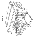
FIG. 6 is a perspective view showing a configuration of an image forming apparatus in which a present invention is applied; -
FIGS. 7A and7B are diagrams showing configurations of mechanical portions of the image forming apparatus; -
FIGS. 8A and8B are diagrams showing configurations of other mechanical portions of the image forming apparatus; -
FIG. 9 is a perspective diagram showing a configuration of a two-dimensional discharge unit; -
FIG. 10 is a waveform diagram showing an operation when an ink droplet is caused to fly; -
FIGS. 11A to 11C are diagrams showing configurations of other image forming apparatuses; -
FIG. 12 is a diagram showing another arrangement of a two-dimensional discharge unit with respect to a roll shaped recording paper; -
FIG. 13 is a diagram showing an arrangement of two-dimensional discharge units provided on a front and rear of a transport path of the recording paper; -
FIGS. 14A and14B are cross-sectional views showing configurations of a second liquid droplet flight device; -
FIG. 15 is a cross-sectional view showing a configuration of a third liquid droplet flight device; -
FIG. 16 is a front view showing flight electrodes having a comb teeth shape; -
FIG. 17 is a cross-sectional view showing a configuration of a fourth liquid droplet flight device; -
FIG. 18 is a cross-sectional view showing a configuration of a fifth liquid droplet flight device; -
FIG. 19A and FIG. 19B are lateral views showing a configuration of electrode portions having flight electrodes in which ink guiding paths are arranged; and -
FIGS. 20A to 20E are cross-sectional views showing forms in which the flight electrodes are concealed. - Hereinafter, detailed description is given of the present invention with reference to the accompanying drawings.
-
FIG. 1 shown a configuration of a liquid droplet flight device according to the present invention. As shown in the drawing, a liquiddroplet flight device 1 is provided with a liquid droplet discharge means 2, and anopposing electrode 3 arranged in opposition to the liquid droplet discharge means 2, The liquid droplet discharge means 2 is provided with aliquid retaining section 4 and a flight means 5. Theliquid retaining section 4 is provided with a slit or a pass-through hole (hereinafter referred to as "slit") 6 and is formed with a material having insulating properties. As shown in the cross-sectional view ofFIG. 2 , the flight means 5 is provided with a rod-shaped flight electrode 7, aninsulating film 8 arranged on an outer circumferential surface of theflight electrode 7, an electrowetting drive electrode (hereinafter, referred to as "EW drive electrode") 9 arranged on an outer circumferential surface of theinsulating film 8, aninsulating film 10 that covers an outer circumferential surface of theEW drive electrode 9, and a water-repellent film 11 arranged on an outer circumferential surface of theinsulating film 10, and a leading edge portion thereof is arranged inside theslit 6 so as to protrude slightly from theslit 6 of theliquid retaining section 4. A liquid-absorbing material such as a sponge for example may also be provided in theslit 6. - The
flight electrode 7 is a material having conductive properties and anti-discharge properties, for example, copper and tungsten, or a carbon or the like, and is formed having an outer diameter of 0.005 to 0.03 mm, for example, 0.015 mm. TheEW drive electrode 9 is a material having good conductive properties, for example, copper and tungsten, or a carbon for the like, and is formed having a thickness of 0.001 to 0.005 mm, for example, 0.001 mm. Theflight electrode 7 and theEW drive electrode 9 are formed using an etching or spattering method, or a CVD method. The insulatingfilm 8 and the insulatingfilm 10 are materials having good insulating properties and anti-discharge properties, for example, SiO2, and are formed having a thickness of 0.001 to 0.005 mm, for example, 0.001 mm. The water-repellent film 11 is formed with a fluorine-based resin for example. A high-viscosity liquid 12 having insulating properties, for example an ink having a viscosity of 8 mPa·s or more, is retained in theliquid retaining section 4, and the width of theslit 6 is determined in accordance with an outer diameter of theflight electrode 7, and in a case where the outer diameter of theflight electrode 7 is 0.015 mm, and for example is formed to approximately 0.2 mm so as to be capable of ensuring a flow channel cross-sectional area sufficient for replenishing ink that has flown. The opposingelectrode 3 is formed with a material having good conductive properties, copper for example, and is arranged leaving a space of 0.01 to 0.5 mm from the leading edge of theflight electrode 7, for example 0.2 mm. - The
flight electrode 7 is connected to the opposingelectrode 3 via abias power source 13, and a high voltage bias voltage of approximately 2 kV for example is applied to it from thebias power source 13. TheEW drive electrode 9 is connected to the liquid 12 of theliquid retaining section 4 via adrive power source 14 and a fright control means 15, and a low voltage drive voltage of 100 V or less is applied to it. Thebias power source 13, thedrive power source 14, and the flight control means 15 are controlled by acontrol device 16 as shown in the block diagram ofFIG. 3 . Preferably, the liquid droplet discharge means is an ink droplet discharge means and the liquid holding section is an ink holding section. The flight electrode and the electrowetting drive electrode respectively comprise one or more electrodes. - When liquid droplets of the liquid 12 inside the
liquid retaining section 4 are caused to fly to a medium 17 that is transported between the liquid droplet discharge means 2 and the opposingelectrode 3 in the liquiddroplet flight device 1, thecontrol device 16 applies a high voltage to theflight electrode 7 from thebias power source 13 such that anelectric field 18 is produced between theflight electrode 7 and the opposingelectrode 3 as shown inFIG. 1 . At this time, aslit 6 side surface of the liquid 12 inside theslit 6 of theliquid retaining section 4 is positioned inside theslit 6, which is outside an electric field 18of theflight electrode 7 due to a meniscus produced due a water-repellent effect of the water-repellent film 11 of the flight means 5. In this state, thecontrol device 16 performs on/off control on the flight control means 15 and applies a low voltage drive voltage to theEW drive electrode 9 from thedrive power source 14. When the drive voltage is applied to the EW deriveelectrode 9, the liquid 12 inside theslit 6 moves to the leading edge portion of theflight electrode 7 as shown inFIG. 4 due to an electrowetting phenomenon. That is, when a drive voltage is applied between theEW drive electrode 9 and the liquid 12 inside theliquid retaining section 4, thereby applying an electric charge to charge the liquid 12, the surface tension of the liquid 12 is reduced so as to improve the wetness properties with the water-repellent film 11, and the surface of the liquid 12 inside theslit 6 moves to the leading edge portion of theflight electrode 7, Since a high electric field is being produced between the leading edge portion of theflight electrode 7, which is to where the surface of the liquid 12 has moved, and the opposingelectrode 3, the liquid 12 that has moved to the leading edge portion of theflight electrode 7 flies toward the opposingelectrode 3 through this electric field such that aliquid droplet 12a lands on the medium 17. - In this manner, by merely performing on/off control on the drive voltage applied to the
EW drive electrode 9, a low voltage of 100 V or less for example, aliquid droplet 12a of the liquid 12 inside the liquid, retainingsection 4 can be caused to fly, and a low cost can be achieved for the liquiddroplet flight device 1 by simplifying the configuration of the flight control means 15. - Furthermore, by applying a drive voltage to the
flight electrode 7 to move the liquid 12 inside theslit 6 to the leading edge portion offlight electrode 7 using an electrowetting phenomenon, ahigh viscosity liquid 12 can be caused to fly stably. - Description is given regarding an image forming apparatus in which the liquid
droplet flight device 1 is used. As shown inFIGS. 5A and5B , the image forming apparatus is provided with a one-dimensional discharge unit 20 in which a plurality of flight means 5a to 5n are arranged in a comb teeth manner at an image resolution pitch in theliquid retaining section 4 of theslit 6 of the liquiddroplet flight device 1. The opposingelectrode 3 is arranged in opposition to the leading edge portions of the pointedflight electrodes 7 of the flight means 3a to 5n, and arecording paper 17 is supplied that is transported by atransport belt 68 between theflight electrodes 7 and the opposingelectrode 3. And theflight electrodes 7 of the flight means 5a to 5n are connected to thebias power source 13, and theEW drive electrodes 9 are connected to thedrive power source 14 via respectiveflight control sections 15a to 15n, such thatink 12 is charged near where thecorresponding flight electrodes 7 are arranged. Trailing edge portions, which are not arranged in theliquid retaining section 4, of theflight electrodes 7 of the plurality of flight means 5a to 5n are integrally linked. These linkedflight electrodes 7 may be formed using etching to have uniform microscopic intervals. - As shown in the perspective drawing of
FIG. 6 , animage forming apparatus 51 provided with the one-dimensional discharge unit 20 is provided with apaper supply tray 52, which is mounted on the apparatus main unit and accommodates recording papers, and apaper discharge tray 53, which is mounted on the apparatus main unit and stacks recording papers on which images have been recorded. An openable/closeableupper cover 54 is provided on an upper side of the apparatus main unit. Furthermore, acartridge loading section 56 is provided at one end portion of afront surface 55 of the apparatus main unit protruding forwardly and at a lower position than theupper cover 54, and anoperation section 57 including operation keys and a display device and the like is provided above thecartridge loading section 56. An opcnable/closeable front cover 58 is provided at a front surface of thecartridge loading section 56 and by opening thefront cover 58,ink cartridges 59, which are the main tanks for replenishing ink, can be removed and attached. - The mechanical portion of the
image forming apparatus 51 may use either a carriage movement method or a line head method. As shown in the lateral structural diagram ofFIG. 7A and the top view structural diagram ofFIG. 7B , the mechanical portion of a carriage movement method involves acarriage 63 being slidably supported in a main scanning direction by aguide rod 61, which is a guiding member extending laterally between side panels of the apparatusmain unit 51, and astay 62, and being moved and scanned in a carriage main scanning direction by a main scanning motor. Mounted in thecarriage 63 are four one-dimensionalink discharge units 20 that cause flight of ink droplets of each of the colors yellow (Y), cyan (C), magenta (M), and black (Bk) used in the liquiddroplet flight device 1. Furthermore,sub tanks 64 are mounted in thecarriage 63, which are liquid containers of each color for supplying ink of each of the colors to the one-dimensional discharge units 20. Ink is replenished and supplied to thesub tanks 64 from each theink cartridges 59. As shown in the lateral structural diagram ofFIG. 8A and the top view structural diagram ofFIG. 8B , the mechanical portion of a line head method involves a single or multiple one-dimensional discharge units 20 having a width corresponding to the paper width of therecording paper 17 being arranged in an array in ahead holder 631 to perform printing while therecording paper 17 is moved at a constant velocity. - A crescent shaped roller (paper supply roller) 66, which separates and feeds the
recording papers 17 sheet by sheet from apaper loading section 65, and aseparating pad 67, which faces thepaper supply roller 66, is constituted by a material having a large friction coefficient, and applies bias toward thepaper supply roller 66, are provided as a paper supply section for supplying therecording papers 17 loaded on the paper loading section (pressing board) 65 of thepaper supply tray 52. And provided as a transport section for transporting therecording papers 17 supplied from thepaper supply tray 52 below the one-dimensional discharge units 20 from theguide 68 are: atransport belt 69 for transporting therecording papers 17, acounter roller 70 for transporting therecording papers 17 sent via theguide 67 from the paper supply section sandwiched against thetransport belt 69, atransport guide 71 for performing direction conversion of approximately 90 degrees on therecording paper 17 that has been sent substantially vertically to align with thetransport belt 69, and a leadingedge pressure roller 73 that biases thetransport belt 69 using a pressingmember 72. Furthermore, an opposingelectrode 3 that is in opposition to each of the flight means 5 of the one-dimensionalink discharge units 20 is arranged at a rear side of thetransport belt 69. Thetransport belt 69 is an endless belt and is constructed so as to rotate around and span between atransport roller 74 and atension roller 75. Thetransport belt 69 has a two layer structure, and the inner side thereof may have a metal conductive member such as nickel. Furthermore, when a high voltage is applied from thetransport roller 74 to the conductive member of thetransport belt 69, this may be used instead of the opposingelectrode 3. - A separating
claw 76 for separating therecording paper 17 from thetransport belt 69, adischarge roller 77, and a dischargesmall roller 78 are provided as a discharge section for discharging therecording papers 17 that have been recorded on by the one-dimensional discharge units 20, and apaper discharge tray 53 is provided under thedischarge roller 77. Furthermore, a double-sidepaper supply unit 79 is attachably mounted at a rear surface portion of the apparatusmain unit 51. The double-sidepaper supply unit 79 rotates in a reverse direction to thetransport belt 69 to take in and turn over therecording paper 17 that has been returned and resend it to thetransport belt 59. A manualpaper feeding section 80 is arranged on an upper surface of the double-sidepaper supply unit 79. - When printing is performed on the
recording paper 17 in the image forming apparatus, the drive voltages applied to theEW drive electrodes 9 of the flight means 5a to 5n of the one-dimensional discharge unit 20 are turned on and off by their respectiveflight control sections 15a to 15n in response to the image data to be printed, thereby causingink droplets 12a to fly due to the electric field produced by thepredetermined flight electrodes 7 such that [the ink droplets] land and are recorded on therecording paper 17 an shown inFIG. 5A . The speed of operation when causing theink droplets 12a to fly depends on the speed theink 12 moves to leading end portions of theflight electrodes 7 due to the electrowetting phenomenon when the drive voltages are applied to theEW drive electrodes 9. The movement speed of theink 12 varies depending on the viscosity of theink 12, but in a case where 0.1 msec is required to move 100 µm for example, the corresponding printing speed is 120 ppm, thus allowing high speeds to be achieved. - Since the one-
dimensional discharge unit 20 is configured in this manner with aliquid retaining section 4 having aslit 6 and a plurality of flight means 5a to 5n, it is possible to achieve a simple structure that is compact and lightweight, and it is also possible to improve reliability and durability since a movable drive section and a heating section are not required. - Furthermore, since the
liquid retaining section 4 is used jointly among the plurality of flight means 5a to 5n to form the ink flow channel including theslit 6 of theliquid retaining section 4, high viscosity inks can be stably supplied into theslit 6 and it is possible to achieve greater speeds in printing and higher image quality. - Furthermore, since it is unnecessary to provide a separate liquid chamber for each of the plurality of flight means 5a to 5n, production is easier and yields at the time of production can be improved. Further still, since the
liquid retaining section 4 is not divided into separate liquid chambers, theliquid retaining section 4 can be used as the ink flow channel and high viscosity inks can be stably and continuously supplied, thereby enabling greater speeds in printing to be achieved. - Furthermore, by arranging at least two rows of the one-
dimensional discharge unit 20 in parallel in a direction orthogonal to theslit 6, it is possible to support a greater number of dots and higher speeds. - Further still, by arranging at least two rows of the one-
dimensional discharge unit 20 such that their phases are shifted by a half pixel in the direction of theslit 6, higher density [printing] can be achieved. - In the foregoing description, description was given regarding a case where the one-
dimensional discharge unit 20 was used in an image forming apparatus, but as shown in the perspective drawing ofFIG. 9 , a two-dimensional discharge unit 21 may be used in which a plurality of flight means 51j (i = a to n, j = a to m) are arranged two-dimensionally. - In an image forming apparatus in which the two-
dimensional discharge unit 21 is used, therecording paper 17 is transported while drive voltages are applied by flight control sections 15ij toEW drive electrodes 9 of a plurality of flight means 5ij in response to image data to achieve flash printing, thereby enabling even greater printing speeds to be achieved. For example, in a case where the transport speed of therecording paper 17 is 1 m/sec, the corresponding printing speed is 286 ppm, enabling printing to be performed at high speed. - Furthermore, when the viscosity of the
ink 12 is high, the speed of theink 12 becomes slower in moving to the leading end portion of theflight electrode 7 due to the electrowetting phenomenon when the drive voltage is applied to theEW drive electrode 9. Even though the movement speed of theink 12 is slower, theink droplets 12a fly due to the electric field produced by theflight electrode 7 when theink 12 moves to the leading end portion of theflight electrode 7 due to the electrowetting phenomenon by the inputting of a pixel signal to the drive voltage to theEW drive electrode 9 as shown in the waveform diagram ofFIG. 10 , and therefore when the speed of theink 12 in moving to the leading end portion of theflight electrode 7 is 210 msec for example, a printing speed is possible of approximately 286 ppm, thus allowing high speed printing even when using thehigh viscosity ink 12. - Furthermore, by providing the two-
dimensional discharge unit 21 on a transport path on which therecording paper 17 is transported by a pair oftransport rollers 741 and a pair oftension rollers 751 arranged before and after a recording region as shown in the lateral configuration diagram of the structural sections of theimage forming apparatus 51 inFIG. 11A , and using the opposingelectrode 3 that faces the two-dimensional discharge unit 21 as a transport guide, it is possible to print an image on therecording paper 17 at high speed. Furthermore, by arranging the two-dimensional discharge unit 21 on the transport path of a roll shapedrecording paper 17 as shown inFIG. 11B , or, as shown inFIG. 11C , by arranging two-dimensional discharge units recording paper 17, it is possible to print a single color image or a full color image at high speed while also achieving compactness in the image forming apparatus. - Further still, as shown in
FIG. 12 , by providing for example four two-dimensional discharge units 21A to 21D on the transport path of a rollpaper recording paper 17 and, with respect to a reference position (x1, y1), arranging the first two-dimensional discharge unit 21A shifted by -1/2 pixel in the X direction and the Y direction for example, then arranging the second two-dimensional discharge unit 21B shifted -1/2 pixel in the X direction and +1/2 pixel in the Y direction, then arranging the third two-dimensional discharge unit 21C shifted +1/2 pixel in the X direction and -1/2 in the Y direction, and arranging the fourth two-dinensional discharge unit 21D shifted +1/2 pixel in the X direction and +1/2 pixel in the Y direction, then applying drive voltages to the four two-dimensional discharge units 21A to 21D using the same pixel signal, a pixel density of 600 dpi for example can be increased in density to 1,200 dpi. - Furthermore, by alternately arranging two-
dimensional discharge units 21 on a front side and a rear side along the transport direction of the transport path of therecording paper 17 as shown inFIG. 13 , therecording paper 17 can be printed continuously on both sides, thereby enabling improved printing efficiency. Further still, by alternately arranging the two-dimensional discharge units recording paper 17, it is possible to ensure a drying time for the ink that has flown onto therecording paper 17. - In the foregoing description, description was given regarding a case where the flight means 5 of the liquid droplet discharge means 2 was provided independent from the
liquid retaining section 4, but as shown in the cross-sectional views ofFIG. 14A and14B , the flight means 5 may be arranged along awall surface 4a that forms theslit 6 of theliquid retaining section 4 such that the flight means 5 is integrated with one side of thewall surface 4a of theliquid retaining section 4. In this case, theEW drive electrode 9 is provided in a region of half of an outer circumferential surface of the insulatingfilm 8 that covers an outer circumferential surface of theflight electrode 7, and an outer circumferential surface of theEW drive electrode 9 is covered by the insulatingfilm 10 and the water-repellent film 11, then a region of the insulatingfilm 8 covering the outer circumferential surface of theflight electrode 7 where theEW drive electrode 9 is not provided is secured along thewall surface 4a of the side where theslit 6 of theliquid retaining section 4 is formed. - By providing the flight means 5 in this manner along the
wall surface 4a of the side where theslit 6 of theliquid retaining section 4 is formed, the flight means 5 can be held stably, and the flight means 5 can be held simply. - Here,
FIG. 14A shows a case where theflight electrode 7 is entirely aligned with thewall surface 4a where theslit 6 of theliquid retaining section 4 is formed, andFIG. 14B shows a case where the leading end portion of theflight electrode 7 that produces the electric field is apart by a fixed interval from thewall surface 4a where theslit 6 of theliquid retaining section 4 is formed. As shown inFIG. 14B , by setting apart the leading end portion of theflight electrode 7 that produces the electric field from thewall surface 4a, the electric field that is produced can be better stabilized. - In the foregoing descriptions, description was given regarding a case where the flight means 5 of the liquid droplet discharge means 2 was formed integrally with the
flight electrode 7 and theEM drive electrode 9, but as shown inFIG. 15 , theflight electrode 7 may be arranged inside theslit 6 of theliquid retaining section 4 with outer circumferential surfaces thereof covered by the water-repellent film 11, and theEW drive electrodes 9 may be provided in portions corresponding to theflight electrode 7 at bothwall surfaces slit 6 of theliquid retaining section 4 is formed. In this case, the outer circumferential surfaces of theEW drive electrodes 9 may be covered by the insulatingfilm 10 and [areas] other than attachment surfaces of the insulatingfilm 10 to the wall surfaces 4a and 4b may be covered by the water-repellent film 11. - By providing the
EW drive electrodes 9 on bothwall surfaces slit 6 of theliquid retaining section 4 is formed in this manner, theink 12 can be moved very efficiently to the leading end portion of theflight electrode 7 using the electrowetting phenomenon and printing speeds can be further increased. - Furthermore, by using etching or the like to integrally form a plurality of
flight electrodes 7 in a comb teeth manner as shown inFIG. 16 when forming the one-dimensional discharge unit 20 or the two-dimensional discharge unit 21, and forming the insulatingfilm 8 on the outer circumferential surface of each of theflight electrodes 7, flight electrode pairs 22 can be manufactured easily. - Further still, by making the leading end of the
flight electrode 7 acute as shown inFIG. 17 , the electric field produced by theflight electrodes 7 can be further stabilized and theink 12 moved by the electrowetting phenomenon can be moved easily to the leading end portion of theflight electrode 7, thereby enabling further increased printing speeds to be achieved. - Furthermore, the
EW drive electrode 9 may be formed integrally with theflight electrode 7 as shown inFIG. 18 and the water-repellent film 11 may also be provided on bothwall surfaces slit 6 of theliquid retaining section 4. - In the foregoing descriptions, description was given regarding cases where the
ink 12 in theslit 6 of theliquid retaining section 4 was moved using an electrowetting phenomenon at a leading end of theflight electrode 7, but as shown in the lateral view ofFIG. 19A and the bottom view ofFIG. 19B , instead of theslit 6, a single or multipleink guiding paths 23 that are U-shaped, V-shaped, or spiral may be provided in the flight means 5 having theflight electrode 7, such that theink 12 retained in theliquid retaining section 4 is guided to the ink guiding path(s) 23, and theink 12 is moved to the leading end of theflight electrode 7 using an electrowetting phenomenon. - Furthermore, in the foregoing descriptions, description was given regarding cases where a rod shaped
flight electrode 7 was provided in the flight means 5 of the liquiddroplet flight device 1, which caused theink droplets 12a to fly using the one-dimensional discharge unit 20 or the two-dimensional discharge unit 21 in whichink droplets 12a of the image forming apparatus were caused to fly, but as shown inFIG. 20A , the leading end portion that is arranged inside theslit 6 of theliquid retaining section 4 of theflight electrode 7 may be formed into a flat shape, and as shown inFIG. 20B , the leading end portion that is arranged inside theslit 6 of theliquid retaining section 4 of theflight electrode 7 may be formed into a cylindrical shape, and as shown inFIG. 20C , the leading end portion that is arranged inside theslit 6 of theliquid retaining section 4 of theflight electrode 7 may be formed into a globular shape, and as shown inFIG. 20D , the leading end portion that is arranged inside theslit 6 of theliquid retaining section 4 of theflight electrode 7 may be formed into a truncated cone shape with an acute portion provided at the leading end, and as shown inFIG. 20E , theflight electrode 7 arranged inside the slit of theliquid retaining section 4 may take a ball pen shape, and various other shapes can be employed. - Hereinafter, examples are given of effects of the present invention.
- (1) By applying a low voltage between the EW drive electrode and the liquid inside the liquid retaining section by the flight control means while a high voltage is applied between the flight electrode, which is arranged in a liquid holding section that holds liquid of the liquid retaining section, and the opposing electrode to cause the liquid of the liquid holding section to move within an electric field generated by the flight electrode using an electrowetting phenomenon, thereby causing a liquid droplet to fly onto a medium arranged between the liquid droplet discharge means and the opposing electrode, it is possible to cause liquid droplets to fly stably using a low voltage and the structure of the flight control means can be simplified such that a low cost can be achieved for the liquid droplet flight device.
- (2) By applying a drive voltage to the flight electrode to move the liquid inside the liquid holding section, which is constituted by a slit or pass-through holes, until, a leading end portion of the flight electrode using the electrowetting phenomenon, high viscosity liquids can be caused to fly stably.
- (3) By integrally forming the EW drive electrode with the flight electrode along an outer circumferential surface of the flight electrode, and providing an insulating water-repellant film at an outer circumferential surface of the EM drive electrode, the structure of the flight electrode and the EM drive electrode can be simplified and can be positioned stably within the liquid holding section.
- (4) By integrally forming EM drive electrode with the flight electrode along an outer circumferential surface of Lhe flight electrode, providing an insulating water-repellant film at an outer circumferential surface of the EW drive electrode, and forming a liquid holding section of the liquid retaining section using a groove formed along the insulating water-repllant film, the flight electrode, the EW drive electrode, and the liquid holding section can be formed using a simple structure.
- (5) Furthermore, by making the leading end portion of the flight electrode acute, the liquid inside the liquid holding section can be moved to the leading end portion of the flight electrode using the electrowetting phenomenon and the strength of the electric field that is generated can be increased such that the efficiency of liquid droplet flight can be improved and higher speeds can be achieved.
- (6) Further still, by arranging the EW drive electrode on a wall surface parallel to the flight electrode of the liquid holding section, arranging the flight electrode on a wall surface of the liquid holding section, and arranging the EW drive electrode on a wall surface opposing the wall surface of the liquid holding section where the flight electrode is arranged, the liquid inside the liquid holding section can be moved with greater efficiency to the leading end portion of the flight electrode using the electrowetting phenomenon.
- (7) Furthermore, by causing ink droplets to fly onto a recording medium using a liquid droplet flight device according to the present invention to form an image, it is possible to form high image quality images stably and to achieve faster printing speeds.
- Various modifications will become possible for those skilled in the art after receiving the teachings of the present disclosure without departing from the scope thereof.
Claims (15)
- A liquid droplet flight device, comprising:liquid droplet discharge means (2); andan opposing electrode (3) arranged opposite to the liquid droplet discharge means (2), whereinthe liquid droplet discharge means (2) is provided with a liquid retaining section (4) having a liquid holding section that is configured to hold a liquid (12) to be caused to fly, and flight means (5) that is configured to cause the liquid (12) held in the liquid holding section to fly,the flight means (5) is provided with a needle-shaped flight electrode (7) arranged inside the liquid holding section, electric field generating means for generating an electric field (18) between the flight electrode (7) and the opposing electrode (3), an electrowetting drive electrode (EW drive electrode) (9) arranged inside the liquid holding section, and flight control means (15) for moving the liquid (12) of the liquid holding section to the electric field (18) generated by the flight electrode (7) of the electric field generating means using an electrowetting phenomenon, by applying a voltage between the EW drive electrode (9) and the liquid (12) inside the liquid retaining section (4), anda low voltage is applied between the EW drive electrode (9) and the liquid (12) inside the liquid retaining section (4) by the flight control means (15) while a high voltage is applied between the flight electrode (7) and the opposing electrode (3) by the electric field generating means, in order to cause a liquid droplet to fly onto a medium (17) arranged between the liquid droplet discharge means (2) and the opposing electrode (3).
- The liquid droplet flight device as claimed in claim 1, wherein the liquid holding section of the liquid retaining section (4) is formed in a slit shape and/or is formed using a pass-through hole.
- The liquid droplet flight device as claimed in 1, wherein the EW drive electrode (9) is integrally formed with the flight electrode (7) along an outer circumferential surface of the flight electrode (7), an insulating water-repellant film (11) is provided at an outer circumferential surface of the EW drive electrode (9), and/or a liquid holding section of the liquid retaining section (4) is formed using a groove formed along the insulating water-repeilant film (11).
- The liquid droplet flight device as claimed in 1, wherein a leading end portion of the flight electrode (7) is acute.
- The liquid droplet flight device as claimed in 1, wherein the EW drive electrode (9) is arranged on a wall surface parallel to the flight electrode (7) of the liquid holding section.
- The liquid droplet flight device as claimed in 1, wherein the flight electrode (7) is arranged on a wall surface of the liquid holding section, and the EW drive electrode (9) is arranged on a wall surface opposing a wall surface of the liquid holding section where the flight electrode (7) is arranged.
- The liquid droplet flight device as claimed in claim 1, wherein the flight means is arranged two-dimensionally inside the liquid holding section.
- The liquid droplet flight device as claimed in claim 1, comprising a material that absorbs ink in the ink holding section.
- The liquid droplet flight device as claimed in claim 1, wherein a plurality of flight electrodes are arranged in an array having an image resolution pitch.
- The liquid droplet flight device as claimed in claim 1, wherein a viscosity of liquid retained in the liquid retaining section (4) is at least 8 mPa·s.
- The liquid droplet flight device as claimed in claim 1, wherein a voltage to be applied to the EW drive electrodes by the flight control means is set smaller than 1/10 of a voltage to be applied between the flight electrodes and the opposing electrode by the electric field generating means.
- The liquid droplet flight device as claimed in claim 1, wherein at least two rows of the liquid droplet discharge means are arranged parallel to a direction orthogonal to the slit shaped or on a-dimensionally arranged plurality of pass-through holes.
- The liquid droplet flight device as claimed in claim 1, wherein the at least two rows of the liquid droplet discharge means are arranged in an array having different phases in a direction of the slit shaped or one-dimensionally arranged plurality of pass-through holes.
- The liquid droplet flight device as claimed in claim 1, wherein the flight control means (15) of the liquid droplet flight device applies a voltage between the EW drive electrodes and the liquid near each of the flight electrodes inside the liquid retaining section (4) in response to image data, in order to perform flash printing on the medium (17) being transported.
- An image forming apparatus, characterized in that the image forming apparatus (51) is provided with an ink droplet flight device (1) according to claims 1 to 14.
Applications Claiming Priority (2)
| Application Number | Priority Date | Filing Date | Title |
|---|---|---|---|
| JP2007215461A JP5009089B2 (en) | 2007-08-22 | 2007-08-22 | Droplet flying apparatus and image forming apparatus |
| JP2007215498A JP5006136B2 (en) | 2007-08-22 | 2007-08-22 | Image forming apparatus |
Publications (2)
| Publication Number | Publication Date |
|---|---|
| EP2028009A1 true EP2028009A1 (en) | 2009-02-25 |
| EP2028009B1 EP2028009B1 (en) | 2010-02-24 |
Family
ID=40193650
Family Applications (1)
| Application Number | Title | Priority Date | Filing Date |
|---|---|---|---|
| EP08162738A Ceased EP2028009B1 (en) | 2007-08-22 | 2008-08-21 | Liquid Droplet Flight Device and Image Forming Apparatus |
Country Status (3)
| Country | Link |
|---|---|
| US (1) | US8373732B2 (en) |
| EP (1) | EP2028009B1 (en) |
| DE (1) | DE602008000699D1 (en) |
Families Citing this family (2)
| Publication number | Priority date | Publication date | Assignee | Title |
|---|---|---|---|---|
| JP5504916B2 (en) * | 2010-01-26 | 2014-05-28 | 株式会社リコー | Droplet discharge apparatus and image forming apparatus |
| JP2021000763A (en) | 2019-06-21 | 2021-01-07 | 株式会社リコー | Head drive device, liquid ejection device and head drive method |
Citations (6)
| Publication number | Priority date | Publication date | Assignee | Title |
|---|---|---|---|---|
| JPH01206062A (en) * | 1988-02-12 | 1989-08-18 | Ricoh Co Ltd | Electrostatic ink jet recorder |
| JPH11198381A (en) | 1998-01-06 | 1999-07-27 | Hitachi Ltd | Ink jet image forming apparatus |
| JP2002172787A (en) * | 2000-12-08 | 2002-06-18 | Ricoh Co Ltd | Recording method using liquid developer |
| JP2004165587A (en) | 2002-02-21 | 2004-06-10 | National Institute Of Advanced Industrial & Technology | Superfine fluid jet device |
| EP1439064A1 (en) * | 2003-01-15 | 2004-07-21 | Samsung Electronics Co., Ltd. | Ink ejecting method and ink-jet printhead adopting the method |
| US20070097162A1 (en) * | 2003-08-08 | 2007-05-03 | Konica Minolta Holdings, Inc. | Liquid ejection apparatus, liquid ejection method, and method for forming wiring pattern of circuit board |
Family Cites Families (10)
| Publication number | Priority date | Publication date | Assignee | Title |
|---|---|---|---|---|
| SE371902B (en) * | 1973-12-28 | 1974-12-02 | Facit Ab | |
| US5293678A (en) * | 1992-02-28 | 1994-03-15 | Comm/Scope | Method for upgrading and converting a coaxial cable with a fiber optic cable |
| JP2807169B2 (en) * | 1994-04-12 | 1998-10-08 | 第一電波工業株式会社 | Coaxial cable coupling device and antenna device |
| JP2000127410A (en) * | 1998-10-27 | 2000-05-09 | Hitachi Ltd | Printer |
| JP4054466B2 (en) | 1998-12-10 | 2008-02-27 | 株式会社リコー | Image forming method and apparatus |
| JP2004136652A (en) * | 2002-09-24 | 2004-05-13 | Konica Minolta Holdings Inc | Liquid ejector |
| CN100532103C (en) * | 2002-09-24 | 2009-08-26 | 柯尼卡美能达控股株式会社 | Method for manufacturing electrostatic attraction type liquid discharge head, method for manufacturing nozzle plate, electrostatic attraction type liquid discharge device |
| TWI257351B (en) * | 2003-08-08 | 2006-07-01 | Sharp Kk | Electrostatic attraction fluid ejecting method and electrostatic attraction fluid ejecting device |
| JP4044012B2 (en) * | 2003-08-29 | 2008-02-06 | シャープ株式会社 | Electrostatic suction type fluid discharge device |
| JP2006095767A (en) * | 2004-09-28 | 2006-04-13 | Fuji Photo Film Co Ltd | Image forming device |
-
2008
- 2008-08-19 US US12/194,107 patent/US8373732B2/en active Active
- 2008-08-21 DE DE602008000699T patent/DE602008000699D1/en active Active
- 2008-08-21 EP EP08162738A patent/EP2028009B1/en not_active Ceased
Patent Citations (7)
| Publication number | Priority date | Publication date | Assignee | Title |
|---|---|---|---|---|
| JPH01206062A (en) * | 1988-02-12 | 1989-08-18 | Ricoh Co Ltd | Electrostatic ink jet recorder |
| JPH11198381A (en) | 1998-01-06 | 1999-07-27 | Hitachi Ltd | Ink jet image forming apparatus |
| JP2002172787A (en) * | 2000-12-08 | 2002-06-18 | Ricoh Co Ltd | Recording method using liquid developer |
| JP2004165587A (en) | 2002-02-21 | 2004-06-10 | National Institute Of Advanced Industrial & Technology | Superfine fluid jet device |
| EP1477230A1 (en) * | 2002-02-21 | 2004-11-17 | National Institute of Advanced Industrial Science and Technology | Ultra-small diameter fluid jet device |
| EP1439064A1 (en) * | 2003-01-15 | 2004-07-21 | Samsung Electronics Co., Ltd. | Ink ejecting method and ink-jet printhead adopting the method |
| US20070097162A1 (en) * | 2003-08-08 | 2007-05-03 | Konica Minolta Holdings, Inc. | Liquid ejection apparatus, liquid ejection method, and method for forming wiring pattern of circuit board |
Also Published As
| Publication number | Publication date |
|---|---|
| EP2028009B1 (en) | 2010-02-24 |
| DE602008000699D1 (en) | 2010-04-08 |
| US20090051735A1 (en) | 2009-02-26 |
| US8373732B2 (en) | 2013-02-12 |
Similar Documents
| Publication | Publication Date | Title |
|---|---|---|
| US7901034B2 (en) | Image forming device for performing idle discharge | |
| US8899732B2 (en) | Inkjet print head having a pivotably supported membrane and method for manufacturing such a print head | |
| US8919932B2 (en) | Liquid ejection head and image forming apparatus including the liquid ejection head | |
| EP1900529B1 (en) | Liquid ejection head and image forming apparatus using the same | |
| EP3222422B1 (en) | Method for operating an inkjet print head and an inkjet print head assembly | |
| US8251473B2 (en) | Inkjet printing apparatus | |
| US9102147B2 (en) | Liquid discharge head and image forming apparatus | |
| US8991977B2 (en) | Liquid discharge head and image forming apparatus | |
| EP2028009B1 (en) | Liquid Droplet Flight Device and Image Forming Apparatus | |
| WO2016068946A1 (en) | Ink jet printing | |
| US20150015646A1 (en) | Liquid ejection head and image forming apparatus | |
| JP2004216887A (en) | Liquid ejector and liquid ejecting method | |
| US20120218331A1 (en) | Liquid ejecting apparatus and driving method thereof | |
| JP2012236339A (en) | Liquid ejecting apparatus | |
| JP5009089B2 (en) | Droplet flying apparatus and image forming apparatus | |
| JP5009090B2 (en) | Image forming apparatus | |
| JP5006136B2 (en) | Image forming apparatus | |
| JP4938604B2 (en) | Liquid ejection head and image forming apparatus | |
| EP3212420B1 (en) | Ink jet printhead | |
| JP7047423B2 (en) | Liquid discharge head, liquid discharge unit and device for discharging liquid | |
| JP4848850B2 (en) | Inkjet image forming apparatus | |
| US8197036B2 (en) | Liquid discharging head with increased strength and image forming apparatus including the liquid discharging head | |
| JP2021142724A (en) | Piezoelectric actuator, recording head and droplet discharge device | |
| JP2012236340A (en) | Liquid ejecting apparatus | |
| JP2000255066A (en) | Ink jet recorder |
Legal Events
| Date | Code | Title | Description |
|---|---|---|---|
| PUAI | Public reference made under article 153(3) epc to a published international application that has entered the european phase |
Free format text: ORIGINAL CODE: 0009012 |
|
| 17P | Request for examination filed |
Effective date: 20080821 |
|
| AK | Designated contracting states |
Kind code of ref document: A1 Designated state(s): AT BE BG CH CY CZ DE DK EE ES FI FR GB GR HR HU IE IS IT LI LT LU LV MC MT NL NO PL PT RO SE SI SK TR |
|
| AX | Request for extension of the european patent |
Extension state: AL BA MK RS |
|
| GRAP | Despatch of communication of intention to grant a patent |
Free format text: ORIGINAL CODE: EPIDOSNIGR1 |
|
| AKX | Designation fees paid |
Designated state(s): DE FR GB |
|
| GRAS | Grant fee paid |
Free format text: ORIGINAL CODE: EPIDOSNIGR3 |
|
| GRAA | (expected) grant |
Free format text: ORIGINAL CODE: 0009210 |
|
| AK | Designated contracting states |
Kind code of ref document: B1 Designated state(s): DE FR GB |
|
| REG | Reference to a national code |
Ref country code: GB Ref legal event code: FG4D |
|
| REF | Corresponds to: |
Ref document number: 602008000699 Country of ref document: DE Date of ref document: 20100408 Kind code of ref document: P |
|
| PLBE | No opposition filed within time limit |
Free format text: ORIGINAL CODE: 0009261 |
|
| STAA | Information on the status of an ep patent application or granted ep patent |
Free format text: STATUS: NO OPPOSITION FILED WITHIN TIME LIMIT |
|
| 26N | No opposition filed |
Effective date: 20101125 |
|
| REG | Reference to a national code |
Ref country code: FR Ref legal event code: PLFP Year of fee payment: 9 |
|
| REG | Reference to a national code |
Ref country code: FR Ref legal event code: PLFP Year of fee payment: 10 |
|
| REG | Reference to a national code |
Ref country code: FR Ref legal event code: PLFP Year of fee payment: 11 |
|
| PGFP | Annual fee paid to national office [announced via postgrant information from national office to epo] |
Ref country code: FR Payment date: 20180827 Year of fee payment: 11 Ref country code: DE Payment date: 20180823 Year of fee payment: 11 |
|
| PGFP | Annual fee paid to national office [announced via postgrant information from national office to epo] |
Ref country code: GB Payment date: 20180822 Year of fee payment: 11 |
|
| REG | Reference to a national code |
Ref country code: DE Ref legal event code: R119 Ref document number: 602008000699 Country of ref document: DE |
|
| GBPC | Gb: european patent ceased through non-payment of renewal fee |
Effective date: 20190821 |
|
| PG25 | Lapsed in a contracting state [announced via postgrant information from national office to epo] |
Ref country code: DE Free format text: LAPSE BECAUSE OF NON-PAYMENT OF DUE FEES Effective date: 20200303 Ref country code: FR Free format text: LAPSE BECAUSE OF NON-PAYMENT OF DUE FEES Effective date: 20190831 |
|
| PG25 | Lapsed in a contracting state [announced via postgrant information from national office to epo] |
Ref country code: GB Free format text: LAPSE BECAUSE OF NON-PAYMENT OF DUE FEES Effective date: 20190821 |