EP2027807A2 - Suction brush for vacuum cleaner - Google Patents
Suction brush for vacuum cleaner Download PDFInfo
- Publication number
- EP2027807A2 EP2027807A2 EP08010872A EP08010872A EP2027807A2 EP 2027807 A2 EP2027807 A2 EP 2027807A2 EP 08010872 A EP08010872 A EP 08010872A EP 08010872 A EP08010872 A EP 08010872A EP 2027807 A2 EP2027807 A2 EP 2027807A2
- Authority
- EP
- European Patent Office
- Prior art keywords
- cleaned
- motor
- lift plate
- micro switch
- suction brush
- Prior art date
- Legal status (The legal status is an assumption and is not a legal conclusion. Google has not performed a legal analysis and makes no representation as to the accuracy of the status listed.)
- Granted
Links
Images


Classifications
-
- A—HUMAN NECESSITIES
- A47—FURNITURE; DOMESTIC ARTICLES OR APPLIANCES; COFFEE MILLS; SPICE MILLS; SUCTION CLEANERS IN GENERAL
- A47L—DOMESTIC WASHING OR CLEANING; SUCTION CLEANERS IN GENERAL
- A47L9/00—Details or accessories of suction cleaners, e.g. mechanical means for controlling the suction or for effecting pulsating action; Storing devices specially adapted to suction cleaners or parts thereof; Carrying-vehicles specially adapted for suction cleaners
- A47L9/02—Nozzles
- A47L9/06—Nozzles with fixed, e.g. adjustably fixed brushes or the like
- A47L9/066—Nozzles with fixed, e.g. adjustably fixed brushes or the like with adjustably mounted brushes, combs, lips or pads; Height adjustment of nozzle or dust loosening tools
-
- A—HUMAN NECESSITIES
- A47—FURNITURE; DOMESTIC ARTICLES OR APPLIANCES; COFFEE MILLS; SPICE MILLS; SUCTION CLEANERS IN GENERAL
- A47L—DOMESTIC WASHING OR CLEANING; SUCTION CLEANERS IN GENERAL
- A47L9/00—Details or accessories of suction cleaners, e.g. mechanical means for controlling the suction or for effecting pulsating action; Storing devices specially adapted to suction cleaners or parts thereof; Carrying-vehicles specially adapted for suction cleaners
- A47L9/02—Nozzles
- A47L9/06—Nozzles with fixed, e.g. adjustably fixed brushes or the like
Definitions
- the present disclosure relates to a suction brush for a vacuum cleaner. More particularly, the present disclosure relates to a suction brush for a vacuum cleaner capable of automatically controlling a gap between a lower casing provided with a suction port and a surface to be cleaned according to whether the surface to be cleaned is a hard floor or a carpet.
- vacuum cleaners are electric appliances that draw in and collect contaminants from a surface to be cleaned using a suction force generated by a vacuum generator.
- Various types of vacuum cleaners have been developed and used.
- a canister type vacuum cleaner generally includes a main body, a connection part, and a suction brush.
- the vacuum generator such as a suction motor generating the suction force and a contaminants collecting part in which the drawn in contaminants are collected are disposed in the main body.
- the connection part includes a handle grasped by a user, an extension pipe connecting the handle and the suction brush, and a flexible hose connecting the handle and the main body.
- the suction port is formed on a bottom surface of the suction brush so that the suction brush can draw in contaminants from the surface to be cleaned through the suction port.
- the vacuum cleaner may be used to clean the surface to be cleaned such as a hard floor, and a carpet.
- the hard floor refers to surfaces to be cleaned having a smooth surface such as, but not limited to, those formed of stone, wood, and linoleum.
- the suction brush of the vacuum cleaner When cleaning the hard floor, the suction brush of the vacuum cleaner is often stuck to the surface to be cleaned. When the suction brush is stuck to the surface to be cleaned, a handling resistance of the suction brush is increased. So a user is required to apply a greater force to handle the suction brush. When cleaning the surface to be cleaned like the carpet, the suction brush is stuck to the carpet less often than the hard floor. However, when cleaning the carpet, the vacuum cleaner needs to use the suction force greater than that used for cleaning the hard floor in order to draw in contaminants among tight wool or fibers (herein after "wool") of the carpet.
- wool tight wool or fibers
- the handing resistance and suction force of the suction brush with respect to the surface to be cleaned are closely related to a gap between the surface to be cleaned and the bottom surface of the suction brush on which the suction port is formed. That is, as the gap between the surface to be cleaned and the bottom surface of the suction brush decreases, the handling resistance and suction force increase. As the gap between the surface to be cleaned and the bottom surface of the suction brush increases, the handling resistance and suction force decrease.
- the handling resistance is increased so that a user is required to use a lot of force to handle the suction brush. Also, when cleaning the carpet, the suction force is weak so that the suction brush cannot effectively draw in contaminants between wool of the carpet.
- suction brushes that can adjust the gap between the surface to be cleaned and the bottom surface of the suction brush according to types of the surfaces to be cleaned have been developed.
- the suction brushes have a lever projecting from a top surface thereof to be manually handled by a user. Therefore, when cleaning the hard floor, the user controls the lever to increase the gap between the surface to be cleaned and the bottom surface of the suction brush, thereby reducing the handling resistance.
- the user controls the lever to decrease the gap between the surface to be cleaned and the bottom surface of the suction brush, thereby increasing the suction force.
- the suction brush is configured so that the user manually controls the lever to adjust the gap between the bottom surface of the suction brush and the surface to be cleaned, whenever the type of the surface to be cleaned changes, the user should manually control the lever. As a result, the use of the vacuum cleaner may feel onerous.
- An aspect of the present disclosure is to provide a suction brush for a vacuum cleaner that can automatically adjust a gap between a bottom surface thereof on which a suction port is formed and a surface to be cleaned when the surface to be cleaned changes from a hard floor to a carpet or from the carpet to the hard floor.
- a suction brush for a vacuum cleaner which includes an upper casing; a lower casing coupled to the upper casing, and provided with a suction port through which contaminants are drawn in from a surface to be cleaned; a lift plate disposed between the upper casing and the lower casing to move up and down with respect to the lower casing; a lift plate driving part to allow the lift plate to move up and down; and a lift control unit to control the lift plate driving part so that when the surface to be cleaned changes from a hard floor to a carpet, the lift plate is raised, and when the surface to be cleaned changes from the carpet to the hard floor, the lift plate is lowered; wherein the lower casing contacts the surface to be cleaned as the lift plate is raised, and the lower casing is spaced apart from the surface to be cleaned as the lift plate is lowered.
- the lift plate driving part includes a driving shaft disposed parallel to the lift plate above the lift plate; a DC motor to rotate the driving shaft; at least one driving cam formed to project radially from an outer circumferential surface of the driving shaft; and a battery to supply the DC motor with electrical power; wherein a receiving portion is recessed on an upper surface of the lift plate to receive either of the driving shaft or the driving cam.
- the lift plate When the driving shaft is received in the receiving portion, the lift plate is raised with respect to the lower casing. When the driving cam is received in the receiving portion, the lift plate is pressed by the driving cam to lower with respect to the lower casing.
- the lift control unit includes a surface detecting part to detect whether the surface to be cleaned is the hard floor or the carpet; a first DC motor driving part to operate the DC motor so that when the surface to be cleaned changes from the hard floor to the carpet, the driving shaft is received in the receiving portion; and a second DC motor driving part to operate the DC motor so that when the surface to be cleaned changes from the carpet to the hard floor, the driving cam is received in the receiving portion.
- the first DC motor driving part includes a first micro switch disposed near a side of the driving shaft; and a first control cam formed on the driving shaft so that when the driving shaft is received in the receiving portion, the first control cam allows the first micro switch to maintain an open state.
- the second DC motor driving part includes a second micro switch disposed side by side with the first micro switch near the side of the driving shaft; and a second control cam formed on the driving shaft so that when the driving cam is received in the receiving portion, the second control cam allows the second micro switch to maintain an open state.
- the DC motor is electrically connected with the first and second micro switches, wherein when the surface to be cleaned is detected as the carpet, the DC motor rotates in one direction until the first micro switch is in the open state, and wherein when the surface to be cleaned is detected as the hard floor, the DC motor rotates in the same direction until the second micro switch is in the open state.
- the surface detecting part includes a fixing plate horizontally spaced apart from the surface to be cleaned; a third micro switch disposed above the fixing plate and electrically connected with the first micro switch and the second micro switch; and a rotation member rotatably disposed at the fixing plate to have a surface contacting portion formed on one end thereof to contact the surface to be cleaned, and a switch contacting portion formed on the other end thereof to contact a contacting terminal of the third micro switch.
- the suction brush may include a power switch part configured to cut off electrical power supplied from the battery to the DC motor when the suction brush is spaced apart from the surface to be cleaned.
- the gap between the lower casing on which the suction port is formed and the surface to be cleaned can be automatically adjusted according to whether the surface to be cleaned is the hard floor or the carpet.
- the DC motor that rotates only in one direction can be used to adjust the gap between the lower casing and the surface to be cleaned. Therefore, the manufacturing cost may be decreased as compared to the suction brush using a reversible motor.
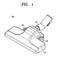
- FIG.1 is a perspective view illustrating a suction brush for a vacuum cleaner according to an exemplary embodiment of the present disclosure.
- FIG. 2 is a perspective view illustrating the suction brush of FIG. 1 with a separated upper casing.
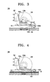
- FIG.3 is a side view illustrating a surface detecting part of the suction brush of FIG.1 locating on a hard floor
- FIG. 4 is a side view illustrating the surface detecting part of the suction brush of FIG.1 locating on a carpet.
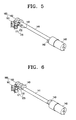
- FIG. 5 is a perspective view illustrating a lift plate driving part, a first DC motor control part, and a second DC motor control part of the suction brush of FIG.1 when locating on the hard floor.
- FIG. 1 is a perspective view illustrating a suction brush for a vacuum cleaner according to an exemplary embodiment of the present disclosure.
- FIG. 2 is a perspective view illustrating the suction brush of FIG. 1 with a separated upper casing.
- FIG.3 is a side view illustrating a surface
- FIG. 6 is a perspective view illustrating the lift plate driving part, the first DC motor control part, and the second DC motor control part of the suction brush of FIG.1 when locating on the carpet.
- FIG. 7 is a sectional perspective view illustrating the suction brush of FIG. 2 taken along a line VII-VII when locating on the hard floor; and
- FIG. 8 is a sectional perspective view illustrating the suction brush of FIG. 2 taken along a line VII-VII when locating on the carpet.
- the suction brush 100 for the vacuum cleaner includes the upper casing 110, a lower casing 120, a lift plate 130, a lift plate driving part 135, and a lift control unit 140.
- the upper casing 110 and the lower casing 120 are coupled each other.
- the lower casing 120 is formed to face a surface to be cleaned during cleaning.
- a suction port 121 through which contaminants are drawn in with air from the surface to be cleaned, is formed at a middle area of the lower casing 120. Contaminants drawn in through the suction port 121 are guided to an extension pipe connector 101 by a guiding passage (not illustrated) formed in the upper casing 110.
- the lift plate 130 is disposed between the upper casing 110 and lower casing 120 to move up and down with respect to the lower casing 120. Referring FIGS. 2 and 7 , a pair of ribs 131 is inserted in opposite ends of the lift plate 130 in a width direction thereof.
- the lift plate 130 moves up, the lower casing 120 relatively moves down to closely contact the surface to be cleaned.
- the lift plate 130 moves down, the lower casing 120 relatively moves up to be spaced apart from the surface to be cleaned.
- the lift plate driving part 135 includes a driving shaft 141, a direct current motor (hereinafter, referred to as a DC motor) 142, a pair of driving cams 143, and a battery 144.
- a DC motor direct current motor
- the driving shaft 141 is arranged parallel to the lift plate 130 above the lift plate 130.
- the driving shaft 141 is connected to the DC motor 142 so that the driving shaft 141 is rotated by the DC motor 142.
- the DC motor 142 is electrically connected to the battery 144 to receive electrical power from the battery 144.
- the pair of driving cams 143 is disposed at opposite ends of the driving shaft 141.
- Each of the driving cams 143 is formed substantially in a fan shape and projects from an outer circumferential surface of the driving shaft 141 in a radial direction of the driving shaft 141.
- a receiving portion 132 is recessed on an upper surface of the lift plate 130 to receive the driving cams 143.
- the receiving portion 132 can also receive a portion of the driving shaft 141 below the driving cam 143.
- the driving cam 143 compresses downwardly the lift plate 130 to be lowered relatively with respect to the lower casing 120.
- FIG. 8 when the portion of the driving shaft 141 below the driving cam 143 is received on the receiving portion 132 of the lift plate 130, the lift plate 130 is relatively raised with respect to the lower casing 120.
- the lift control unit 140 controls the lift plate driving part 135 according to types of the surface to be cleaned. For example, when the surface to be cleaned changes from the hard floor to the carpet, the lift control unit 140 controls the lift plate driving part 135 to raise the lift plate 130. When the surface to be cleaned changes from the carpet to the hard floor, the lift control unit 140 controls the lift plate driving part 135 to lower the lift plate 130. Therefore, when the surface to be cleaned is the carpet, the lower casing 120 is maintained in close contact with the carpet by the lift control unit 140. When the surface to be cleaned is the hard floor, the lower casing 120 is maintained spaced apart from the hard floor by the lift control unit 140.
- the lift control unit 140 includes the surface detecting part 150, a first DC motor driving part 160, and a second DC motor driving part 170.
- the surface detecting part 150 is disposed between a pair of suction brush wheels 102 and detects whether the surface to be cleaned is the hard floor or the carpet.
- the surface detecting part 150 includes a fixing plate 151, a third micro switch 152, and a rotation member 153.
- the fixing plate 151 is spaced in a predetermined height apart from the surface to be cleaned and remains substantially horizontal with respect to the surface to be cleaned.
- the third micro switch 152 is disposed above the fixing plate 151 and has a contacting terminal 152a disposed near the rotation member 153.
- the third micro switch 152 is electrically connected with first and second micro switches 161 and 162, which will be described later.
- the rotation member 153 is rotatably disposed at the fixing plate 151. At one end of the rotation member 153 is formed a surface contacting portion 153a that can contact the surface to be cleaned. At the other end of the rotation member 153 is formed a switch contacting portion 153b that can contact the contacting terminal 152a of the third micro switch 152.
- the surface contacting portion 153a and switch contacting portion 153b may be formed in a roller.
- the switch contacting portion 153b of the rotation member 153 does not contact and is spaced apart from the contacting terminal 152a.
- the state where the switch contacting portion 153b is spaced apart from the contacting terminal 152a of the third micro switch 152 is hereafter referred to as an open state of the third micro switch 152.
- the surface contacting portion 153a of the rotation member 153 is raised as much as the height of wool W of the carpet.
- the height of fixing plate 151 from the surface to be cleaned is maintained constantly so that the rotation member 153 rotates by a predetermined angle.
- the switch contacting portion 153b of the rotation member 153 is lowered to contact and press the contacting terminal 152a of the third micro switch 152.
- the state where the switch contacting portion 153b contacts and presses the contacting terminal 152a of the third micro switch 152 is hereafter referred to as a closed state of the third micro switch 152.
- a first length L1 from a rotation center 153c to the switch contacting portion 153b of the rotation member 153 may be longer than a second length L2 from the rotation center 153c to the surface contacting portion 153a of the rotation member 153.
- the first length L1 from the rotation center 153c to the switch contacting portion 153b of the rotation member 153 is approximately five times as long as the second length L2 from the rotation center 153c to the surface contacting portion 153a of the rotation member 153.
- the switch contacting portion 153b is lowered by approximately 5mm.
- the first DC motor driving part 160 includes the first micro switch 161 disposed near a side of the driving shaft 141, and a first control cam 162 that opens and closes the first micro switch 161.
- the first control cam 162 when the driving cam 143 locates below the driving shaft 141 to be received in the receiving portion 132 of the lift plate 130, the first control cam 162 causes the first micro switch 161 to be in a closed state. As illustrated in FIGS. 6 and 8 , when the driving shaft 141 locates below the driving cam 143 to be received in the receiving portion 132 of the lift plate 130, the first control cam 162 causes the first micro switch 161 to be in an open state.
- the closed state of the first micro switch 161 refers to a state that a contacting terminal of the first micro switch 161 is pressed by an outer circumferential surface of the first control cam 162 as illustrated in FIG. 7 .
- the open state of the first micro switch 161 refers to a state that the contacting terminal of the first micro switch 161 locates in a recess portion 162a of the outer circumferential surface of the first control cam 162 and is not pressed by the outer circumferential surface of the first control cam 162 as illustrated in FIG. 8 .
- the electrical connection between the first micro switch 161 and the DC motor 142 is maintained.
- the electrical connection between the first micro switch 161 and the DC motor 142 is cut off.
- the surface detecting part 150 detects the carpet, that is, the third micro switch 152 is in the closed state (see FIG. 4 ), the electrical connection between the second micro switch 171 and the DC motor 142 is cut off. As a result, the rotation of the DC motor 152 is controlled by open and closed operations of the first micro switch 161 regardless of the second micro switch 171.
- the DC motor 142 may be set to operate.
- the third micro switch 152 is closed so that the DC motor 142 is controlled by the first micro switch 161.
- the first micro switch 161 maintains the closed state on the hard floor as illustrated in FIG. 7 so that the DC motor 142 operates the driving shaft 141 to rotate.
- the driving shaft 141 rotates by approximately 180 degrees
- the first micro switch 161 is in the open state as illustrated in FIG. 8 so that the DC motor 142 stops.
- the second DC motor driving part 170 includes the second micro switch 171 disposed side by side with the first micro switch 161 near the side of the driving shaft 141, and a second control cam 172 that opens and closes the second micro switch 171.
- the second control cam 172 causes the second micro switch 171 to be in an open state.
- the second control cam 172 causes the second micro switch 171 to be in a closed state.
- the closed state of the second micro switch 171 refers to a state where a contacting terminal of the second micro switch 171 is pressed by an outer circumferential surface of the second control cam 172 as illustrated in FIG. 8 .
- the open state of the second micro switch 171 refers to a state where the contacting terminal of the second micro switch 171 is located in a recess portion 172a of the outer circumferential surface of the second control cam 172 and is not pressed by the outer circumferential surface of the second control cam 172 as illustrated in FIG. 7 .
- the surface detecting part 150 detects the hard floor, that is, the third micro switch 152 is in the open state (see FIG. 3 ), the electrical connection between the first micro switch 161 and the DC motor 142 is cut off. As a result, the rotation of the DC motor 142 is controlled by opening and closing the second micro switch 171 regardless of the first micro switch 161. When the second micro switch 171 is in the closed state, the DC motor 142 may be set to operate.
- the third micro switch 152 is in the open state so that the DC motor 142 is controlled by the second micro switch 171.
- the second micro switch 171 is maintained in the closed state on the carpet as illustrated in FIG. 8 so that the DC motor 142 operates the driving shaft 141 to rotate.
- the driving shaft 141 rotates by approximately 180 degrees
- the second micro switch 171 is in the open state as illustrated in FIG. 7 so that the DC motor 142 stops.
- the DC motor 142 rotates the driving shaft 141 by approximately 180 degrees until the first micro switch 161 changes from the closed state to the open state.
- the DC motor 142 rotates the driving shaft 141 by another approximately 180 degrees until the second micro switch 171 changes from the closed state to the open state.
- the driving shaft 141 is required to rotate by approximately 180 degrees regardless of a rotational direction. Therefore, the DC motor 142 is not required to use a reversible motor. A motor that rotates only in one direction can be used as the DC motor 142.
- the suction brush 100 is provided with a power switch part 180 that cuts off the electric power supplied from the battery 144 to the DC motor 142.
- a power switch (not illustrated) that can contact the surface to be cleaned can be disposed on a bottom of the power switch part 180.
- the power switch contacts the surface to be cleaned so that the electric power is supplied from the battery 144 to the DC motor 142.
- the power switch is turned off so that an electrical connection between the battery 144 and the DC motor 142 is cut off. As a result, the electric power is not supplied from the battery 144 to the DC motor 142.
- the driving cam 143 presses the receiving portion 132 of the lift plate 130.
- the lift plate 130 is lowered, so the lower casing 120 is relatively raised. Therefore, a gap between the lower casing 120 and the surface to be cleaned is greater when the surface to be cleaned is the hard floor than when the surface to be cleaned is the carpet. As a result, it is reduced that the lower casing 120 is stuck to the surface to be cleaned due to the suction force. Therefore, the handling resistance of the suction brush 100 can be decreased.
- the switch contacting portion 153b of the rotation member 153 is spaced apart from the contacting terminal 152a of the third micro switch 152 so that the third micro switch 152 maintains the open state.
- the surface detecting part 150 detects the surface to be cleaned as the hard floor.
- the second DC motor driving part 170 controls the DC motor 142.
- the DC motor 142 operates to rotate the driving shaft 141.
- the second micro switch 171 is in the open state so that the DC motor 142 does not operate.
- the switch contacting portion 153b of the rotation member 153 contacts and presses the contacting terminal 152a of the third micro switch 152. Therefore, the surface detecting part 150 changes so as to detect the surface to be cleaned as the carpet.
- the first DC motor driving part 160 controls the DC motor 142.
- the DC motor 142 operates to rotate the driving shaft 141.
- the first micro switch 161 is maintained in the closed state by the first driving cam 162 so that the DC motor 142 operates to rotate the driving shaft 141 in a direction.
- the driving cam 162 allows the first micro switch 161 to move to the open state as illustrated in FIG. 8 so that the DC motor 142 stops.
- the portion of the driving shaft 141 below the driving cam 143 is received in the receiving portion 132 of the lift plate 130 so that the lift plate 130 is raised and the lower casing 120 is relatively lowered. Therefore, the lower casing 120 closely contacts the carpet as compared to the hard floor. As a result, the suction brush 100 can effectively draw in contaminants among wool W of the carpet.
- the surface detecting part 150 changes from the state of FIG. 4 to the state of FIG. 3 . That is, the surface detecting part 150 changes to detect the surface to be cleaned as the hard floor.
- the power switch of the power switch part 180 (see FIG. 8 ) disposed at the suction brush 100 is turned off to prevent the DC motor 142 from operating.
- the lower casing 120 When the user is cleaning the carpet, the lower casing 120 maintains close contact with the carpet as illustrated in FIG. 8 . At this time, the surface detecting part 150 of the suction brush 100 allows the third micro switch 152 to maintain the closed state as illustrated in FIG. 4 .
- the third micro switch 152 is in the open state so that the surface detecting part 150 detects the surface to be cleaned as the hard floor.
- the second DC motor driving part 170 controls the DC motor 142.
- the DC motor 142 operates to rotate the driving shaft 141.
- the second micro switch 171 is maintained in the closed state by the second driving cam 172 so that the DC motor 142 operates to rotate the driving shaft 141 in the direction.
- the second driving cam 172 allows the second micro switch 171 to move to the open state as illustrated in FIG. 7 so that the DC motor 142 stops.
- the driving cam 143 is received in the receiving portion 132 of the lift plate 130 so that the lift plate 130 is pressed by the driving cam 143 to be lowered, and the lower casing 120 is relatively raised. Therefore, the gap between the lower casing 120 and the surface to be cleaned becomes greater when the surface to be cleaned is the hard floor than when the surface to be cleaned is the carpet. As a result, a phenomenon that the lower casing 120 is stuck to the surface to be cleaned due to the suction force may be reduced. Therefore, the handling resistance of the suction brush 100 can be decreased.
Abstract
Description
- The present disclosure relates to a suction brush for a vacuum cleaner. More particularly, the present disclosure relates to a suction brush for a vacuum cleaner capable of automatically controlling a gap between a lower casing provided with a suction port and a surface to be cleaned according to whether the surface to be cleaned is a hard floor or a carpet.
- Generally, vacuum cleaners are electric appliances that draw in and collect contaminants from a surface to be cleaned using a suction force generated by a vacuum generator. Various types of vacuum cleaners have been developed and used. A canister type vacuum cleaner generally includes a main body, a connection part, and a suction brush.
- The vacuum generator such as a suction motor generating the suction force and a contaminants collecting part in which the drawn in contaminants are collected are disposed in the main body. The connection part includes a handle grasped by a user, an extension pipe connecting the handle and the suction brush, and a flexible hose connecting the handle and the main body. Also, the suction port is formed on a bottom surface of the suction brush so that the suction brush can draw in contaminants from the surface to be cleaned through the suction port.
- The vacuum cleaner may be used to clean the surface to be cleaned such as a hard floor, and a carpet. Here, the hard floor refers to surfaces to be cleaned having a smooth surface such as, but not limited to, those formed of stone, wood, and linoleum.
- When cleaning the hard floor, the suction brush of the vacuum cleaner is often stuck to the surface to be cleaned. When the suction brush is stuck to the surface to be cleaned, a handling resistance of the suction brush is increased. So a user is required to apply a greater force to handle the suction brush. When cleaning the surface to be cleaned like the carpet, the suction brush is stuck to the carpet less often than the hard floor. However, when cleaning the carpet, the vacuum cleaner needs to use the suction force greater than that used for cleaning the hard floor in order to draw in contaminants among tight wool or fibers (herein after "wool") of the carpet.
- The handing resistance and suction force of the suction brush with respect to the surface to be cleaned are closely related to a gap between the surface to be cleaned and the bottom surface of the suction brush on which the suction port is formed. That is, as the gap between the surface to be cleaned and the bottom surface of the suction brush decreases, the handling resistance and suction force increase. As the gap between the surface to be cleaned and the bottom surface of the suction brush increases, the handling resistance and suction force decrease.
- Therefore, in the case of the suction brush constantly maintaining the gap between the surface to be cleaned and the bottom surface of the suction brush, when cleaning the hard floor, the handling resistance is increased so that a user is required to use a lot of force to handle the suction brush. Also, when cleaning the carpet, the suction force is weak so that the suction brush cannot effectively draw in contaminants between wool of the carpet.
- To solve the problem, suction brushes that can adjust the gap between the surface to be cleaned and the bottom surface of the suction brush according to types of the surfaces to be cleaned have been developed. The suction brushes have a lever projecting from a top surface thereof to be manually handled by a user. Therefore, when cleaning the hard floor, the user controls the lever to increase the gap between the surface to be cleaned and the bottom surface of the suction brush, thereby reducing the handling resistance. When cleaning the carpet, the user controls the lever to decrease the gap between the surface to be cleaned and the bottom surface of the suction brush, thereby increasing the suction force.
- However, because the suction brush is configured so that the user manually controls the lever to adjust the gap between the bottom surface of the suction brush and the surface to be cleaned, whenever the type of the surface to be cleaned changes, the user should manually control the lever. As a result, the use of the vacuum cleaner may feel onerous.
- The present disclosure has been developed in order to overcome the above drawbacks and other problems associated with the conventional arrangement. An aspect of the present disclosure is to provide a suction brush for a vacuum cleaner that can automatically adjust a gap between a bottom surface thereof on which a suction port is formed and a surface to be cleaned when the surface to be cleaned changes from a hard floor to a carpet or from the carpet to the hard floor.
- The above aspect and/or other features of the present disclosure can substantially be achieved by providing a suction brush for a vacuum cleaner, which includes an upper casing; a lower casing coupled to the upper casing, and provided with a suction port through which contaminants are drawn in from a surface to be cleaned; a lift plate disposed between the upper casing and the lower casing to move up and down with respect to the lower casing; a lift plate driving part to allow the lift plate to move up and down; and a lift control unit to control the lift plate driving part so that when the surface to be cleaned changes from a hard floor to a carpet, the lift plate is raised, and when the surface to be cleaned changes from the carpet to the hard floor, the lift plate is lowered; wherein the lower casing contacts the surface to be cleaned as the lift plate is raised, and the lower casing is spaced apart from the surface to be cleaned as the lift plate is lowered.
- The lift plate driving part includes a driving shaft disposed parallel to the lift plate above the lift plate; a DC motor to rotate the driving shaft; at least one driving cam formed to project radially from an outer circumferential surface of the driving shaft; and a battery to supply the DC motor with electrical power; wherein a receiving portion is recessed on an upper surface of the lift plate to receive either of the driving shaft or the driving cam.
- When the driving shaft is received in the receiving portion, the lift plate is raised with respect to the lower casing. When the driving cam is received in the receiving portion, the lift plate is pressed by the driving cam to lower with respect to the lower casing.
- The lift control unit includes a surface detecting part to detect whether the surface to be cleaned is the hard floor or the carpet; a first DC motor driving part to operate the DC motor so that when the surface to be cleaned changes from the hard floor to the carpet, the driving shaft is received in the receiving portion; and a second DC motor driving part to operate the DC motor so that when the surface to be cleaned changes from the carpet to the hard floor, the driving cam is received in the receiving portion.
- The first DC motor driving part includes a first micro switch disposed near a side of the driving shaft; and a first control cam formed on the driving shaft so that when the driving shaft is received in the receiving portion, the first control cam allows the first micro switch to maintain an open state.
- The second DC motor driving part includes a second micro switch disposed side by side with the first micro switch near the side of the driving shaft; and a second control cam formed on the driving shaft so that when the driving cam is received in the receiving portion, the second control cam allows the second micro switch to maintain an open state.
- The DC motor is electrically connected with the first and second micro switches, wherein when the surface to be cleaned is detected as the carpet, the DC motor rotates in one direction until the first micro switch is in the open state, and wherein when the surface to be cleaned is detected as the hard floor, the DC motor rotates in the same direction until the second micro switch is in the open state.
- The surface detecting part includes a fixing plate horizontally spaced apart from the surface to be cleaned; a third micro switch disposed above the fixing plate and electrically connected with the first micro switch and the second micro switch; and a rotation member rotatably disposed at the fixing plate to have a surface contacting portion formed on one end thereof to contact the surface to be cleaned, and a switch contacting portion formed on the other end thereof to contact a contacting terminal of the third micro switch.
- The suction brush may include a power switch part configured to cut off electrical power supplied from the battery to the DC motor when the suction brush is spaced apart from the surface to be cleaned.
- With the suction brush of the vacuum cleaner according to an embodiment of the present disclosure, the gap between the lower casing on which the suction port is formed and the surface to be cleaned can be automatically adjusted according to whether the surface to be cleaned is the hard floor or the carpet.
- Also, with the suction brush of the vacuum cleaner according to an embodiment of the present disclosure, the DC motor that rotates only in one direction can be used to adjust the gap between the lower casing and the surface to be cleaned. Therefore, the manufacturing cost may be decreased as compared to the suction brush using a reversible motor.
- Other objects, advantages and salient features of the disclosure will become apparent from the following detailed description, which, taken in conjunction with the annexed drawings, discloses preferred embodiments of the disclosure.
- These and/or other aspects and advantages of the disclosure will become apparent and more readily appreciated from the following description of the embodiments, taken in conjunction with the accompanying drawings of which:
-
FIG.1 is a perspective view illustrating a suction brush for a vacuum cleaner according to an embodiment of the present disclosure; -
FIG. 2 is a perspective view illustrating the suction brush ofFIG.1 with a separated upper casing; -
FIG. 3 is a side view illustrating a surface detecting part of the suction brush ofFIG.1 locating on a hard floor; -
FIG. 4 is a side view illustrating a surface detecting part of the suction brush ofFIG.1 locating on a carpet; -
FIG. 5 is a perspective view illustrating a lift plate driving part, a first DC motor control part, and a second DC motor control part of the suction brush ofFIG.1 when locating on a hard floor; -
FIG. 6 is a perspective view illustrating a lift plate driving part, a first DC motor control part, and a second DC motor control part of the suction brush ofFIG.1 when locating on a carpet; -
FIG. 7 is a sectional perspective view illustrating the suction brush ofFIG. 2 taken along a line VII-VII when locating on a hard floor; and -
FIG. 8 is a sectional perspective view illustrating the suction brush ofFIG. 2 taken along a line VII-VII when locating on a carpet. - Throughout the drawings, like reference numerals will be understood to refer to like parts, components and structures.
- Hereinafter, a suction brush for a vacuum cleaner according to an exemplary embodiment of the present disclosure will be described in detail with reference to the accompanying drawings.
- The matters defined in the description, such as a detailed construction and elements thereof, are provided to assist in a comprehensive understanding of the disclosure. Thus, it is apparent that the present disclosure may be carried out without those defined matters. Also, well-known functions or constructions are omitted to provide a clear and concise description of exemplary embodiments of the present disclosure.
-
FIG.1 is a perspective view illustrating a suction brush for a vacuum cleaner according to an exemplary embodiment of the present disclosure.FIG. 2 is a perspective view illustrating the suction brush ofFIG. 1 with a separated upper casing.FIG.3 is a side view illustrating a surface detecting part of the suction brush ofFIG.1 locating on a hard floor, andFIG. 4 is a side view illustrating the surface detecting part of the suction brush ofFIG.1 locating on a carpet.FIG. 5 is a perspective view illustrating a lift plate driving part, a first DC motor control part, and a second DC motor control part of the suction brush ofFIG.1 when locating on the hard floor.FIG. 6 is a perspective view illustrating the lift plate driving part, the first DC motor control part, and the second DC motor control part of the suction brush ofFIG.1 when locating on the carpet.FIG. 7 is a sectional perspective view illustrating the suction brush ofFIG. 2 taken along a line VII-VII when locating on the hard floor; andFIG. 8 is a sectional perspective view illustrating the suction brush ofFIG. 2 taken along a line VII-VII when locating on the carpet. - Referring to
FIGS.1 to 8 , thesuction brush 100 for the vacuum cleaner according to this embodiment includes theupper casing 110, alower casing 120, alift plate 130, a liftplate driving part 135, and alift control unit 140. - The
upper casing 110 and thelower casing 120 are coupled each other. Thelower casing 120 is formed to face a surface to be cleaned during cleaning. Asuction port 121, through which contaminants are drawn in with air from the surface to be cleaned, is formed at a middle area of thelower casing 120. Contaminants drawn in through thesuction port 121 are guided to anextension pipe connector 101 by a guiding passage (not illustrated) formed in theupper casing 110. - The
lift plate 130 is disposed between theupper casing 110 andlower casing 120 to move up and down with respect to thelower casing 120. ReferringFIGS. 2 and7 , a pair ofribs 131 is inserted in opposite ends of thelift plate 130 in a width direction thereof. When thelift plate 130 moves up, thelower casing 120 relatively moves down to closely contact the surface to be cleaned. When thelift plate 130 moves down, thelower casing 120 relatively moves up to be spaced apart from the surface to be cleaned. - Referring to
FIGS. 2 ,5, and 6 , the liftplate driving part 135 includes a drivingshaft 141, a direct current motor (hereinafter, referred to as a DC motor) 142, a pair of drivingcams 143, and abattery 144. - The driving
shaft 141 is arranged parallel to thelift plate 130 above thelift plate 130. The drivingshaft 141 is connected to theDC motor 142 so that the drivingshaft 141 is rotated by theDC motor 142. TheDC motor 142 is electrically connected to thebattery 144 to receive electrical power from thebattery 144. The pair of drivingcams 143 is disposed at opposite ends of the drivingshaft 141. Each of the drivingcams 143 is formed substantially in a fan shape and projects from an outer circumferential surface of the drivingshaft 141 in a radial direction of the drivingshaft 141. - Referring to
FIGS. 7 and 8 , a receivingportion 132 is recessed on an upper surface of thelift plate 130 to receive the drivingcams 143. The receivingportion 132 can also receive a portion of the drivingshaft 141 below the drivingcam 143. As seen inFIG. 7 , when the drivingcam 143 is received on the receivingportion 132 of thelift plate 130, the drivingcam 143 compresses downwardly thelift plate 130 to be lowered relatively with respect to thelower casing 120. As seen inFIG. 8 , when the portion of the drivingshaft 141 below the drivingcam 143 is received on the receivingportion 132 of thelift plate 130, thelift plate 130 is relatively raised with respect to thelower casing 120. - The
lift control unit 140 controls the liftplate driving part 135 according to types of the surface to be cleaned. For example, when the surface to be cleaned changes from the hard floor to the carpet, thelift control unit 140 controls the liftplate driving part 135 to raise thelift plate 130. When the surface to be cleaned changes from the carpet to the hard floor, thelift control unit 140 controls the liftplate driving part 135 to lower thelift plate 130. Therefore, when the surface to be cleaned is the carpet, thelower casing 120 is maintained in close contact with the carpet by thelift control unit 140. When the surface to be cleaned is the hard floor, thelower casing 120 is maintained spaced apart from the hard floor by thelift control unit 140. - The
lift control unit 140, referring toFIGS. 2 ,5, and 6 , includes thesurface detecting part 150, a first DCmotor driving part 160, and a second DCmotor driving part 170. - Referring to
FIG. 2 , thesurface detecting part 150 is disposed between a pair ofsuction brush wheels 102 and detects whether the surface to be cleaned is the hard floor or the carpet. Referring toFIGS. 3 and 4 , thesurface detecting part 150 includes a fixingplate 151, a thirdmicro switch 152, and arotation member 153. - The fixing
plate 151 is spaced in a predetermined height apart from the surface to be cleaned and remains substantially horizontal with respect to the surface to be cleaned. - The third
micro switch 152 is disposed above the fixingplate 151 and has a contacting terminal 152a disposed near therotation member 153. The thirdmicro switch 152 is electrically connected with first and secondmicro switches - The
rotation member 153 is rotatably disposed at the fixingplate 151. At one end of therotation member 153 is formed asurface contacting portion 153a that can contact the surface to be cleaned. At the other end of therotation member 153 is formed aswitch contacting portion 153b that can contact the contacting terminal 152a of the thirdmicro switch 152. Thesurface contacting portion 153a andswitch contacting portion 153b may be formed in a roller. - When the surface to be cleaned is the hard floor as illustrated in
FIG. 3 , theswitch contacting portion 153b of therotation member 153 does not contact and is spaced apart from the contacting terminal 152a. The state where theswitch contacting portion 153b is spaced apart from the contacting terminal 152a of the thirdmicro switch 152 is hereafter referred to as an open state of the thirdmicro switch 152. - When the surface to be cleaned changes into the carpet as illustrated in
FIG. 4 , thesurface contacting portion 153a of therotation member 153 is raised as much as the height of wool W of the carpet. At this time, the height of fixingplate 151 from the surface to be cleaned is maintained constantly so that therotation member 153 rotates by a predetermined angle. So, theswitch contacting portion 153b of therotation member 153 is lowered to contact and press the contacting terminal 152a of the thirdmicro switch 152. The state where theswitch contacting portion 153b contacts and presses the contacting terminal 152a of the thirdmicro switch 152 is hereafter referred to as a closed state of the thirdmicro switch 152. - A first length L1 from a
rotation center 153c to theswitch contacting portion 153b of therotation member 153 may be longer than a second length L2 from therotation center 153c to thesurface contacting portion 153a of therotation member 153. In this embodiment, the first length L1 from therotation center 153c to theswitch contacting portion 153b of therotation member 153 is approximately five times as long as the second length L2 from therotation center 153c to thesurface contacting portion 153a of therotation member 153. In this case, when thesurface contacting portion 153a is raised by approximately 1mm, theswitch contacting portion 153b is lowered by approximately 5mm. As a result, even when the surface to be cleaned is a carpet with relatively short wool W, thesurface detecting part 150 can detect whether the surface to be cleaned is the carpet. - Referring to
FIGS. 5 to 8 , the first DCmotor driving part 160 includes the firstmicro switch 161 disposed near a side of the drivingshaft 141, and afirst control cam 162 that opens and closes the firstmicro switch 161. - As illustrated in
FIGS. 5 and7 , when the drivingcam 143 locates below the drivingshaft 141 to be received in the receivingportion 132 of thelift plate 130, thefirst control cam 162 causes the firstmicro switch 161 to be in a closed state. As illustrated inFIGS. 6 and8 , when the drivingshaft 141 locates below the drivingcam 143 to be received in the receivingportion 132 of thelift plate 130, thefirst control cam 162 causes the firstmicro switch 161 to be in an open state. - Here, the closed state of the first
micro switch 161 refers to a state that a contacting terminal of the firstmicro switch 161 is pressed by an outer circumferential surface of thefirst control cam 162 as illustrated inFIG. 7 . The open state of the firstmicro switch 161 refers to a state that the contacting terminal of the firstmicro switch 161 locates in arecess portion 162a of the outer circumferential surface of thefirst control cam 162 and is not pressed by the outer circumferential surface of thefirst control cam 162 as illustrated inFIG. 8 . When the firstmicro switch 161 is in the closed state, the electrical connection between the firstmicro switch 161 and theDC motor 142 is maintained. However, when the firstmicro switch 161 is in the open state, the electrical connection between the firstmicro switch 161 and theDC motor 142 is cut off. - When the
surface detecting part 150 detects the carpet, that is, the thirdmicro switch 152 is in the closed state (seeFIG. 4 ), the electrical connection between the secondmicro switch 171 and theDC motor 142 is cut off. As a result, the rotation of theDC motor 152 is controlled by open and closed operations of the firstmicro switch 161 regardless of the secondmicro switch 171. When the firstmicro switch 161 is in the closed state, theDC motor 142 may be set to operate. - For example, when the surface to be cleaned changes from the hard floor to the carpet, as illustrated in
FIG. 4 , the thirdmicro switch 152 is closed so that theDC motor 142 is controlled by the firstmicro switch 161. At this time, the firstmicro switch 161 maintains the closed state on the hard floor as illustrated inFIG. 7 so that theDC motor 142 operates the drivingshaft 141 to rotate. When the drivingshaft 141 rotates by approximately 180 degrees, the firstmicro switch 161 is in the open state as illustrated inFIG. 8 so that theDC motor 142 stops. - Referring to
FIGS. 5 to 8 , the second DCmotor driving part 170 includes the secondmicro switch 171 disposed side by side with the firstmicro switch 161 near the side of the drivingshaft 141, and asecond control cam 172 that opens and closes the secondmicro switch 171. - As illustrated in
FIGS. 5 and7 , when the drivingcam 143 is located below the drivingshaft 141 so as to be received in the receivingportion 132 of thelift plate 130, thesecond control cam 172 causes the secondmicro switch 171 to be in an open state. As illustrated inFIGS. 6 and8 , when the drivingshaft 141 is located below the drivingcam 143 so that the portion of the drivingshaft 141 below the drivingcam 143 is received in the receivingportion 132 of thelift plate 130, thesecond control cam 172 causes the secondmicro switch 171 to be in a closed state. - Here, the closed state of the second
micro switch 171 refers to a state where a contacting terminal of the secondmicro switch 171 is pressed by an outer circumferential surface of thesecond control cam 172 as illustrated inFIG. 8 . The open state of the secondmicro switch 171 refers to a state where the contacting terminal of the secondmicro switch 171 is located in arecess portion 172a of the outer circumferential surface of thesecond control cam 172 and is not pressed by the outer circumferential surface of thesecond control cam 172 as illustrated inFIG. 7 . When the secondmicro switch 171 is in the closed state, the electrical connection between the secondmicro switch 171 and theDC motor 142 is maintained. However, when the secondmicro switch 171 is in the open state, the electrical connection between the secondmicro switch 171 and theDC motor 142 is cut off. - When the
surface detecting part 150 detects the hard floor, that is, the thirdmicro switch 152 is in the open state (seeFIG. 3 ), the electrical connection between the firstmicro switch 161 and theDC motor 142 is cut off. As a result, the rotation of theDC motor 142 is controlled by opening and closing the secondmicro switch 171 regardless of the firstmicro switch 161. When the secondmicro switch 171 is in the closed state, theDC motor 142 may be set to operate. - For example, when the surface to be cleaned changes from the carpet to the hard floor, as illustrated in
FIG. 3 , the thirdmicro switch 152 is in the open state so that theDC motor 142 is controlled by the secondmicro switch 171. At this time, the secondmicro switch 171 is maintained in the closed state on the carpet as illustrated inFIG. 8 so that theDC motor 142 operates the drivingshaft 141 to rotate. When the drivingshaft 141 rotates by approximately 180 degrees, the secondmicro switch 171 is in the open state as illustrated inFIG. 7 so that theDC motor 142 stops. - As described above, when the surface to be cleaned changes from the hard floor to the carpet, the
DC motor 142 rotates the drivingshaft 141 by approximately 180 degrees until the firstmicro switch 161 changes from the closed state to the open state. When the surface to be cleaned changes from the carpet to the hard floor, theDC motor 142 rotates the drivingshaft 141 by another approximately 180 degrees until the secondmicro switch 171 changes from the closed state to the open state. - In the present disclosure, when the surface to be cleaned changes from the hard floor to the carpet or from the carpet to the hard floor, the driving
shaft 141 is required to rotate by approximately 180 degrees regardless of a rotational direction. Therefore, theDC motor 142 is not required to use a reversible motor. A motor that rotates only in one direction can be used as theDC motor 142. - Referring to
FIG. 2 , thesuction brush 100 is provided with apower switch part 180 that cuts off the electric power supplied from thebattery 144 to theDC motor 142. Although not illustrated, a power switch (not illustrated) that can contact the surface to be cleaned can be disposed on a bottom of thepower switch part 180. When thesuction brush 100 is on the surface to be cleaned, the power switch contacts the surface to be cleaned so that the electric power is supplied from thebattery 144 to theDC motor 142. However, when thesuction brush 100 is spaced apart from the surface to be cleaned, the power switch is turned off so that an electrical connection between thebattery 144 and theDC motor 142 is cut off. As a result, the electric power is not supplied from thebattery 144 to theDC motor 142. - Hereinafter, operations of the
suction brush 100 for the vacuum cleaner according to an embodiment of the present disclosure having the above-described structure will be explained when the surface to be cleaned changes from the hard floor to the carpet during a cleaning work and when the surface to be cleaned changes from the carpet to the hard floor during the cleaning work. - First, when the surface to be cleaned changes from the hard floor to the carpet during the cleaning work, the operation of the
suction brush 100 is explained with reference toFIGS. 3, 4 ,7, and 8 . - When a user is cleaning the hard floor using the
suction brush 100, as illustrated inFIG. 7 , the drivingcam 143 presses the receivingportion 132 of thelift plate 130. At this time, thelift plate 130 is lowered, so thelower casing 120 is relatively raised. Therefore, a gap between thelower casing 120 and the surface to be cleaned is greater when the surface to be cleaned is the hard floor than when the surface to be cleaned is the carpet. As a result, it is reduced that thelower casing 120 is stuck to the surface to be cleaned due to the suction force. Therefore, the handling resistance of thesuction brush 100 can be decreased. - When the user is cleaning the hard floor using the
suction brush 100, as illustrated inFIG. 3 , theswitch contacting portion 153b of therotation member 153 is spaced apart from the contacting terminal 152a of the thirdmicro switch 152 so that the thirdmicro switch 152 maintains the open state. In other words, thesurface detecting part 150 detects the surface to be cleaned as the hard floor. When the surface to be cleaned is detected as the hard floor, the second DCmotor driving part 170 controls theDC motor 142. For example, when the secondmicro switch 171 is in the closed state, theDC motor 142 operates to rotate the drivingshaft 141. However, if the surface to be cleaned is the hard floor, as illustrated inFIG. 7 , the secondmicro switch 171 is in the open state so that theDC motor 142 does not operate. - When the user moves the
suction brush 100 from the hard floor to the carpet, that is, the surface to be cleaned changes from the hard floor to the carpet, as illustrated inFIG. 4 , theswitch contacting portion 153b of therotation member 153 contacts and presses the contacting terminal 152a of the thirdmicro switch 152. Therefore, thesurface detecting part 150 changes so as to detect the surface to be cleaned as the carpet. - When the surface to be cleaned is detected as the carpet, the first DC
motor driving part 160 controls theDC motor 142. For example, when the firstmicro switch 161 is in the closed state, theDC motor 142 operates to rotate the drivingshaft 141. When the surface to be cleaned changes from the hard floor to the carpet, as illustrated inFIG. 7 , the firstmicro switch 161 is maintained in the closed state by thefirst driving cam 162 so that theDC motor 142 operates to rotate the drivingshaft 141 in a direction. When the drivingshaft 141 rotates by approximately 180 degrees in the direction, thefirst driving cam 162 allows the firstmicro switch 161 to move to the open state as illustrated inFIG. 8 so that theDC motor 142 stops. - During this process, the portion of the driving
shaft 141 below the drivingcam 143 is received in the receivingportion 132 of thelift plate 130 so that thelift plate 130 is raised and thelower casing 120 is relatively lowered. Therefore, thelower casing 120 closely contacts the carpet as compared to the hard floor. As a result, thesuction brush 100 can effectively draw in contaminants among wool W of the carpet. - When the user is cleaning the carpet, the user can lift up the
suction brush 100 to be spaced apart from the carpet. At this time, thesurface detecting part 150 changes from the state ofFIG. 4 to the state ofFIG. 3 . That is, thesurface detecting part 150 changes to detect the surface to be cleaned as the hard floor. However, when the user lifts up thesuction brush 100, the power switch of the power switch part 180 (seeFIG. 8 ) disposed at thesuction brush 100 is turned off to prevent theDC motor 142 from operating. - Next, referring to
FIGS. 3, 4 ,7 and 8 , when the surface to be cleaned changes from the carpet to the hard floor during the cleaning work, the operation of thesuction brush 100 is explained. - When the user is cleaning the carpet, the
lower casing 120 maintains close contact with the carpet as illustrated inFIG. 8 . At this time, thesurface detecting part 150 of thesuction brush 100 allows the thirdmicro switch 152 to maintain the closed state as illustrated inFIG. 4 . - When the user moves the
suction brush 100 from the carpet to the hard floor, that is, the surface to be cleaned changes from the carpet to the hard floor, as illustrated inFIG. 3 , the thirdmicro switch 152 is in the open state so that thesurface detecting part 150 detects the surface to be cleaned as the hard floor. - When the surface to be cleaned is detected as the hard floor, the second DC
motor driving part 170 controls theDC motor 142. For example, when the secondmicro switch 171 is in the closed state, theDC motor 142 operates to rotate the drivingshaft 141. When the surface to be cleaned changes from the carpet to the hard floor, as illustrated inFIG. 8 , the secondmicro switch 171 is maintained in the closed state by thesecond driving cam 172 so that theDC motor 142 operates to rotate the drivingshaft 141 in the direction. When the drivingshaft 141 rotates by approximately 180 degrees in the direction, thesecond driving cam 172 allows the secondmicro switch 171 to move to the open state as illustrated inFIG. 7 so that theDC motor 142 stops. - During this process, the driving
cam 143 is received in the receivingportion 132 of thelift plate 130 so that thelift plate 130 is pressed by the drivingcam 143 to be lowered, and thelower casing 120 is relatively raised. Therefore, the gap between thelower casing 120 and the surface to be cleaned becomes greater when the surface to be cleaned is the hard floor than when the surface to be cleaned is the carpet. As a result, a phenomenon that thelower casing 120 is stuck to the surface to be cleaned due to the suction force may be reduced. Therefore, the handling resistance of thesuction brush 100 can be decreased. - While the embodiments of the present disclosure have been described, additional variations and modifications of the embodiments may occur to those skilled in the art once they learn of the basic inventive concepts. Therefore, it is intended that the appended claims shall be construed to include both the above embodiments and all such variations and modifications that fall within the spirit and scope of the disclosure.
Claims (9)
- A suction brush for a vacuum cleaner comprising:an upper casing (110);a lower casing (120) coupled to the upper casing (110), the lower casing (120) being provided with a suction port (121) through which contaminants are drawn in from a surface to be cleaned;a lift plate (130) disposed between the upper casing (110) and the lower casing (120) so as to move up and down with respect to the lower casing (120);a lift plate driving part (135) to allow the lift plate (130) to move up and down; anda lift control unit (140) to control the lift plate driving part (135) so that when the surface to be cleaned changes from a hard floor to a carpet, the lift plate (130) is raised, and when the surface to be cleaned changes from the carpet to the hard floor, the lift plate (130) is lowered,wherein the lower casing (120) contacts the surface to be cleaned when the lift plate (130) is raised, and the lower casing (120) is spaced apart from the surface to be cleaned when the lift plate (130) is lowered.
- The suction brush of claim 1, wherein the lift plate driving part (135) comprises:a driving shaft (141) disposed parallel to the lift plate (130) above the lift plate;a DC motor (142) configured to rotate the driving shaft (141);at least one driving cam (143) formed to project radially from an outer circumferential surface of the driving shaft (141); anda battery (144) to supply the DC motor (142) with electrical power,wherein a receiving portion (132) is recessed on an upper surface of the lift plate (130) to receive either of the driving shaft (141) or the driving cam (143).
- The suction brush of claim 2, wherein when the driving shaft (141) is received in the receiving portion (132), the lift plate (130) is raised with respect to the lower casing (120), and when the driving cam (143) is received in the receiving portion (132), the lift plate (130) is pressed by the driving cam (143) to lower with respect to the lower casing (120).
- The suction brush of claim 3, wherein the lift control unit (140) comprises:a surface detecting part (150) to detect whether the surface to be cleaned is the hard floor or the carpet;a first DC motor driving part (160) to operate the DC motor (142) so that when the surface to be cleaned changes from the hard floor to the carpet, the driving shaft (141) is received in the receiving portion (132); anda second DC motor driving part (170) to operate the DC motor (142) so that when the surface to be cleaned changes from the carpet to the hard floor, the driving cam (143) is received in the receiving portion (143).
- The suction brush of claim 4, wherein the first DC motor driving part (160) comprises:a first micro switch (161) disposed near a side of the driving shaft (141); anda first control cam (162) formed on the driving shaft (141) so that when the driving shaft (141) is received in the receiving portion (132), the first control cam (162) allows the first micro switch (161) to maintain an open state.
- The suction brush of claim 5, wherein the second DC motor driving part (170) comprises:a second micro switch (171) disposed side by side with the first micro switch (161) near the side of the driving shaft (141); anda second control cam (172) formed on the driving shaft (141) so that when the driving cam (143) is received in the receiving portion (132), the second control cam (172) allows the second micro switch (171) to maintain an open state.
- The suction brush of claim 6, wherein the DC motor (142) is electrically connected with the first and second micro switches (161, 171),
wherein when the surface to be cleaned is detected as the carpet, the DC motor (142) rotates in one direction until the first micro switch (161) is in the open state, and
wherein when the surface to be cleaned is detected as the hard floor, the DC motor (142) rotates in the same direction until the second micro switch (171) is in the open state. - The suction brush of any of claims 4 to 7, wherein the surface detecting part (150) comprises:a fixing plate (151) horizontally spaced apart from the surface to be cleaned;a third micro switch (152) disposed above the fixing plate (151) and electrically connected with the first micro switch (161) and the second micro switch (171); anda rotation member (153) rotatably disposed at the fixing plate (151) to have a surface contacting portion (153a) formed on one end thereof to contact the surface to be cleaned, and a switch contacting portion (153b) formed on the other end thereof to contact a contacting terminal (152a) of the third micro switch (152).
- The suction brush of any of claims 2 to 8, further comprising:a power switch part (180) configured to cut off electrical power supplied from the battery (144) to the DC motor (142) when the suction brush (100) is spaced apart from the surface to be cleaned.
Applications Claiming Priority (1)
| Application Number | Priority Date | Filing Date | Title |
|---|---|---|---|
| KR20070084091A KR101487787B1 (en) | 2007-08-21 | 2007-08-21 | A suction brush for vacuum cleaner |
Publications (3)
| Publication Number | Publication Date |
|---|---|
| EP2027807A2 true EP2027807A2 (en) | 2009-02-25 |
| EP2027807A3 EP2027807A3 (en) | 2010-06-30 |
| EP2027807B1 EP2027807B1 (en) | 2015-04-01 |
Family
ID=40125742
Family Applications (1)
| Application Number | Title | Priority Date | Filing Date |
|---|---|---|---|
| EP08010872.3A Revoked EP2027807B1 (en) | 2007-08-21 | 2008-06-16 | Suction brush for vacuum cleaner |
Country Status (5)
| Country | Link |
|---|---|
| US (1) | US7971315B2 (en) |
| EP (1) | EP2027807B1 (en) |
| JP (1) | JP5156500B2 (en) |
| KR (1) | KR101487787B1 (en) |
| RU (1) | RU2008123223A (en) |
Cited By (3)
| Publication number | Priority date | Publication date | Assignee | Title |
|---|---|---|---|---|
| EP3092929A1 (en) * | 2015-05-15 | 2016-11-16 | Dyson Technology Limited | Floor tool for a vacuum cleaner |
| EP3092930A1 (en) * | 2015-05-15 | 2016-11-16 | Dyson Technology Limited | Floor tool for a vacuum cleaner |
| CN109381115A (en) * | 2017-08-11 | 2019-02-26 | 德国福维克控股公司 | The ground processing equipment of floor treatment element with electrical motor driven |
Families Citing this family (9)
| Publication number | Priority date | Publication date | Assignee | Title |
|---|---|---|---|---|
| KR101373593B1 (en) * | 2009-04-14 | 2014-03-12 | 다이슨 테크놀러지 리미티드 | A cleaner head |
| GB2469456B (en) * | 2009-04-14 | 2013-04-17 | Dyson Technology Ltd | A cleaner head |
| GB2469459B (en) * | 2009-04-14 | 2013-05-22 | Dyson Technology Ltd | A cleaner head |
| JP5636867B2 (en) | 2010-10-19 | 2014-12-10 | 富士通株式会社 | Semiconductor device and manufacturing method of semiconductor device |
| KR101995424B1 (en) * | 2012-06-13 | 2019-07-02 | 엘지전자 주식회사 | Robot Cleaner and Controlling Method for the same |
| CN103494581B (en) * | 2013-09-30 | 2016-04-06 | 苏州德震电器有限公司 | A kind of scrubbing brush of dust catcher |
| DE102015105061B4 (en) | 2015-04-01 | 2022-03-24 | Vorwerk & Co. Interholding Gmbh | cleaning device |
| DE102015117552B4 (en) * | 2015-10-15 | 2024-04-18 | Vorwerk & Co. Interholding Gmbh | Attachment for a household cleaning appliance and household cleaning appliance |
| WO2019143700A1 (en) | 2018-01-17 | 2019-07-25 | Tti (Macao Commercial Offshore) Limited | System and method for operating a cleaning system based on a surface to be cleaned |
Family Cites Families (19)
| Publication number | Priority date | Publication date | Assignee | Title |
|---|---|---|---|---|
| JPS562929Y2 (en) * | 1975-12-11 | 1981-01-22 | ||
| JPS58149143U (en) * | 1982-03-31 | 1983-10-06 | 東芝テック株式会社 | Suction port body for vacuum cleaner |
| US4706327A (en) | 1986-05-30 | 1987-11-17 | Whirlpool Corporation | Automatic vacuum nozzle height adjustment system for vacuum cleaner |
| JP2857947B2 (en) * | 1991-10-07 | 1999-02-17 | 三菱電機ホーム機器株式会社 | Electric vacuum cleaner |
| JPH0652748U (en) * | 1992-12-25 | 1994-07-19 | 東京電気株式会社 | Vacuum cleaner suction body |
| JPH06269382A (en) * | 1993-03-22 | 1994-09-27 | Mitsubishi Electric Home Appliance Co Ltd | Vacuum cleaner |
| JPH07289481A (en) * | 1994-04-28 | 1995-11-07 | Sanyo Electric Co Ltd | Electric cleaner |
| US5970576A (en) * | 1997-03-26 | 1999-10-26 | The Hoover Company | Vacuum cleaner height adjustment |
| US6591447B2 (en) * | 2001-03-19 | 2003-07-15 | The Hoover Company | Spring loaded vacuum cleaner nozzle |
| KR100481666B1 (en) | 2003-04-03 | 2005-04-14 | 주식회사 한울로보틱스 | suction equipment of vacuum cleaning robot worked by motor |
| KR100517930B1 (en) | 2003-05-21 | 2005-09-30 | 엘지전자 주식회사 | Brush height control apparatus of vacuum cleaner |
| KR100517942B1 (en) | 2003-12-22 | 2005-09-30 | 엘지전자 주식회사 | Apparatus for controlling height of suction head in robot cleaner and method thereof |
| KR100595571B1 (en) * | 2004-09-13 | 2006-07-03 | 엘지전자 주식회사 | Robot cleaner |
| US7987552B2 (en) * | 2004-11-17 | 2011-08-02 | Techtronic Floor Care Technology Limited | Floor care appliance with a plurality of cleaning modes |
| JP2007054145A (en) * | 2005-08-23 | 2007-03-08 | Matsushita Electric Ind Co Ltd | Electric cleaner |
| DE102005041809A1 (en) | 2005-09-02 | 2007-03-08 | BSH Bosch und Siemens Hausgeräte GmbH | Vacuum cleaner floor nozzle with switchable bristle strip |
| JP2007075389A (en) * | 2005-09-15 | 2007-03-29 | Matsushita Electric Ind Co Ltd | Suction head and vacuum cleaner using the same |
| KR100734960B1 (en) * | 2006-09-25 | 2007-07-03 | 삼성광주전자 주식회사 | Lifting control apparatus of suction body for upright type vacuum cleaner |
| US20090020141A1 (en) | 2007-07-19 | 2009-01-22 | Dever Kerry L | Floor care apparatus with photoelectric quasi-automatic height adjustment |
-
2007
- 2007-08-21 KR KR20070084091A patent/KR101487787B1/en not_active IP Right Cessation
-
2008
- 2008-01-22 US US12/009,744 patent/US7971315B2/en not_active Expired - Fee Related
- 2008-06-11 RU RU2008123223/12A patent/RU2008123223A/en not_active Application Discontinuation
- 2008-06-16 EP EP08010872.3A patent/EP2027807B1/en not_active Revoked
- 2008-06-20 JP JP2008161549A patent/JP5156500B2/en not_active Expired - Fee Related
Non-Patent Citations (1)
| Title |
|---|
| None |
Cited By (4)
| Publication number | Priority date | Publication date | Assignee | Title |
|---|---|---|---|---|
| EP3092929A1 (en) * | 2015-05-15 | 2016-11-16 | Dyson Technology Limited | Floor tool for a vacuum cleaner |
| EP3092930A1 (en) * | 2015-05-15 | 2016-11-16 | Dyson Technology Limited | Floor tool for a vacuum cleaner |
| CN109381115A (en) * | 2017-08-11 | 2019-02-26 | 德国福维克控股公司 | The ground processing equipment of floor treatment element with electrical motor driven |
| CN109381115B (en) * | 2017-08-11 | 2022-02-01 | 德国福维克控股公司 | Floor treatment device with an electric motor-driven floor treatment element |
Also Published As
| Publication number | Publication date |
|---|---|
| KR101487787B1 (en) | 2015-02-06 |
| JP2009045439A (en) | 2009-03-05 |
| US7971315B2 (en) | 2011-07-05 |
| JP5156500B2 (en) | 2013-03-06 |
| US20090049643A1 (en) | 2009-02-26 |
| EP2027807B1 (en) | 2015-04-01 |
| EP2027807A3 (en) | 2010-06-30 |
| KR20090019560A (en) | 2009-02-25 |
| RU2008123223A (en) | 2009-12-20 |
Similar Documents
| Publication | Publication Date | Title |
|---|---|---|
| US7971315B2 (en) | Suction brush for vacuum cleaner | |
| RU2463945C2 (en) | Suction brush for vacuum cleaner | |
| US9295362B2 (en) | Vacuum cleaner agitator cleaner with power control | |
| KR101322247B1 (en) | suction brush for use in vacuum cleaner and height adjusting method thereof | |
| EP1955637B1 (en) | Vacuum electronic power tool sense | |
| EP2991533B1 (en) | Vacuum cleaner agitator cleaner with power control | |
| JP2007159961A (en) | Vacuum cleaner | |
| JP6492282B2 (en) | Electric vacuum cleaner | |
| KR101322574B1 (en) | Vacuum cleaner hose assembly and vacuum cleaner | |
| WO2018041195A1 (en) | Vacuum dust suction device and control method therefor, and self-moving robot | |
| JP4978223B2 (en) | Vacuum cleaner suction tool and vacuum cleaner using the same | |
| JP4920779B2 (en) | Vacuum cleaner | |
| JP6800048B2 (en) | Suction port for bedding of vacuum cleaner | |
| US7313845B2 (en) | Upright type cleaner | |
| JP2018047051A (en) | Vacuum cleaner | |
| JP2002000526A (en) | Vacuum cleaner | |
| JPH06151A (en) | Suction implement of vacuum cleaner | |
| CN219763219U (en) | Cleaning apparatus | |
| JP3630146B2 (en) | Vacuum cleaner suction tool and vacuum cleaner using the same | |
| JP2003093288A (en) | Suction nozzle for vacuum cleaner | |
| JP3874176B2 (en) | Electric vacuum cleaner | |
| JP2004283215A (en) | Vacuum cleaner | |
| KR101610208B1 (en) | Rotation And Reverse Rotation Cleaner | |
| JP2004105275A (en) | Suction tool for vacuum cleaner, and vacuum cleaner using the same | |
| JP2004154259A (en) | Switch structure for vacuum cleaner |
Legal Events
| Date | Code | Title | Description |
|---|---|---|---|
| PUAI | Public reference made under article 153(3) epc to a published international application that has entered the european phase |
Free format text: ORIGINAL CODE: 0009012 |
|
| AK | Designated contracting states |
Kind code of ref document: A2 Designated state(s): AT BE BG CH CY CZ DE DK EE ES FI FR GB GR HR HU IE IS IT LI LT LU LV MC MT NL NO PL PT RO SE SI SK TR |
|
| AX | Request for extension of the european patent |
Extension state: AL BA MK RS |
|
| PUAL | Search report despatched |
Free format text: ORIGINAL CODE: 0009013 |
|
| AK | Designated contracting states |
Kind code of ref document: A3 Designated state(s): AT BE BG CH CY CZ DE DK EE ES FI FR GB GR HR HU IE IS IT LI LT LU LV MC MT NL NO PL PT RO SE SI SK TR |
|
| AX | Request for extension of the european patent |
Extension state: AL BA MK RS |
|
| RIC1 | Information provided on ipc code assigned before grant |
Ipc: A47L 9/04 20060101ALI20100525BHEP Ipc: A47L 5/34 20060101ALI20100525BHEP Ipc: A47L 9/06 20060101AFI20081229BHEP |
|
| 17P | Request for examination filed |
Effective date: 20101213 |
|
| AKX | Designation fees paid |
Designated state(s): DE FR GB |
|
| RAP1 | Party data changed (applicant data changed or rights of an application transferred) |
Owner name: SAMSUNG ELECTRONICS CO., LTD. |
|
| RAP1 | Party data changed (applicant data changed or rights of an application transferred) |
Owner name: SAMSUNG ELECTRONICS CO., LTD. |
|
| GRAP | Despatch of communication of intention to grant a patent |
Free format text: ORIGINAL CODE: EPIDOSNIGR1 |
|
| INTG | Intention to grant announced |
Effective date: 20141105 |
|
| GRAS | Grant fee paid |
Free format text: ORIGINAL CODE: EPIDOSNIGR3 |
|
| GRAA | (expected) grant |
Free format text: ORIGINAL CODE: 0009210 |
|
| AK | Designated contracting states |
Kind code of ref document: B1 Designated state(s): DE FR GB |
|
| REG | Reference to a national code |
Ref country code: GB Ref legal event code: FG4D |
|
| REG | Reference to a national code |
Ref country code: DE Ref legal event code: R096 Ref document number: 602008037393 Country of ref document: DE Effective date: 20150513 |
|
| REG | Reference to a national code |
Ref country code: FR Ref legal event code: PLFP Year of fee payment: 8 |
|
| PGFP | Annual fee paid to national office [announced via postgrant information from national office to epo] |
Ref country code: DE Payment date: 20150618 Year of fee payment: 8 Ref country code: GB Payment date: 20150617 Year of fee payment: 8 |
|
| PGFP | Annual fee paid to national office [announced via postgrant information from national office to epo] |
Ref country code: FR Payment date: 20150611 Year of fee payment: 8 |
|
| REG | Reference to a national code |
Ref country code: DE Ref legal event code: R026 Ref document number: 602008037393 Country of ref document: DE |
|
| PLBI | Opposition filed |
Free format text: ORIGINAL CODE: 0009260 |
|
| PLAX | Notice of opposition and request to file observation + time limit sent |
Free format text: ORIGINAL CODE: EPIDOSNOBS2 |
|
| 26 | Opposition filed |
Opponent name: WESSEL-WERK GMBH Effective date: 20151230 |
|
| PLBB | Reply of patent proprietor to notice(s) of opposition received |
Free format text: ORIGINAL CODE: EPIDOSNOBS3 |
|
| RDAF | Communication despatched that patent is revoked |
Free format text: ORIGINAL CODE: EPIDOSNREV1 |
|
| REG | Reference to a national code |
Ref country code: DE Ref legal event code: R064 Ref document number: 602008037393 Country of ref document: DE Ref country code: DE Ref legal event code: R103 Ref document number: 602008037393 Country of ref document: DE |
|
| RDAG | Patent revoked |
Free format text: ORIGINAL CODE: 0009271 |
|
| STAA | Information on the status of an ep patent application or granted ep patent |
Free format text: STATUS: PATENT REVOKED |
|
| 27W | Patent revoked |
Effective date: 20160929 |
|
| GBPR | Gb: patent revoked under art. 102 of the ep convention designating the uk as contracting state |
Effective date: 20160929 |