EP2027648B1 - Current limitation for a double-fed asynchronous machine - Google Patents
Current limitation for a double-fed asynchronous machine Download PDFInfo
- Publication number
- EP2027648B1 EP2027648B1 EP07729685A EP07729685A EP2027648B1 EP 2027648 B1 EP2027648 B1 EP 2027648B1 EP 07729685 A EP07729685 A EP 07729685A EP 07729685 A EP07729685 A EP 07729685A EP 2027648 B1 EP2027648 B1 EP 2027648B1
- Authority
- EP
- European Patent Office
- Prior art keywords
- reactive power
- power
- maximum permissible
- output
- input
- Prior art date
- Legal status (The legal status is an assumption and is not a legal conclusion. Google has not performed a legal analysis and makes no representation as to the accuracy of the status listed.)
- Active
Links
- 238000000034 method Methods 0.000 claims abstract description 31
- 238000004364 calculation method Methods 0.000 claims description 9
- 230000001105 regulatory effect Effects 0.000 claims description 7
- 238000000819 phase cycle Methods 0.000 claims 6
- 238000013178 mathematical model Methods 0.000 claims 1
- 238000012423 maintenance Methods 0.000 abstract 1
- 230000006978 adaptation Effects 0.000 description 13
- 101150074732 U gene Proteins 0.000 description 9
- 230000001276 controlling effect Effects 0.000 description 5
- 230000003068 static effect Effects 0.000 description 5
- 238000011156 evaluation Methods 0.000 description 4
- 108090000623 proteins and genes Proteins 0.000 description 3
- 230000009466 transformation Effects 0.000 description 3
- 230000005540 biological transmission Effects 0.000 description 2
- 238000001816 cooling Methods 0.000 description 2
- 230000006698 induction Effects 0.000 description 2
- 101100129500 Caenorhabditis elegans max-2 gene Proteins 0.000 description 1
- 230000033228 biological regulation Effects 0.000 description 1
- 238000013016 damping Methods 0.000 description 1
- 230000001419 dependent effect Effects 0.000 description 1
- 238000005516 engineering process Methods 0.000 description 1
- 230000006870 function Effects 0.000 description 1
- 230000015654 memory Effects 0.000 description 1
- 230000007935 neutral effect Effects 0.000 description 1
- 238000004064 recycling Methods 0.000 description 1
- 238000004804 winding Methods 0.000 description 1
Images


Classifications
-
- H—ELECTRICITY
- H02—GENERATION; CONVERSION OR DISTRIBUTION OF ELECTRIC POWER
- H02J—CIRCUIT ARRANGEMENTS OR SYSTEMS FOR SUPPLYING OR DISTRIBUTING ELECTRIC POWER; SYSTEMS FOR STORING ELECTRIC ENERGY
- H02J3/00—Circuit arrangements for AC mains or AC distribution networks
- H02J3/18—Arrangements for adjusting, eliminating or compensating reactive power in networks
-
- H—ELECTRICITY
- H02—GENERATION; CONVERSION OR DISTRIBUTION OF ELECTRIC POWER
- H02P—CONTROL OR REGULATION OF ELECTRIC MOTORS, ELECTRIC GENERATORS OR DYNAMO-ELECTRIC CONVERTERS; CONTROLLING TRANSFORMERS, REACTORS OR CHOKE COILS
- H02P9/00—Arrangements for controlling electric generators for the purpose of obtaining a desired output
- H02P9/007—Control circuits for doubly fed generators
-
- F—MECHANICAL ENGINEERING; LIGHTING; HEATING; WEAPONS; BLASTING
- F03—MACHINES OR ENGINES FOR LIQUIDS; WIND, SPRING, OR WEIGHT MOTORS; PRODUCING MECHANICAL POWER OR A REACTIVE PROPULSIVE THRUST, NOT OTHERWISE PROVIDED FOR
- F03B—MACHINES OR ENGINES FOR LIQUIDS
- F03B13/00—Adaptations of machines or engines for special use; Combinations of machines or engines with driving or driven apparatus; Power stations or aggregates
- F03B13/12—Adaptations of machines or engines for special use; Combinations of machines or engines with driving or driven apparatus; Power stations or aggregates characterised by using wave or tide energy
-
- G—PHYSICS
- G01—MEASURING; TESTING
- G01R—MEASURING ELECTRIC VARIABLES; MEASURING MAGNETIC VARIABLES
- G01R19/00—Arrangements for measuring currents or voltages or for indicating presence or sign thereof
- G01R19/06—Measuring real component; Measuring reactive component
-
- H—ELECTRICITY
- H02—GENERATION; CONVERSION OR DISTRIBUTION OF ELECTRIC POWER
- H02P—CONTROL OR REGULATION OF ELECTRIC MOTORS, ELECTRIC GENERATORS OR DYNAMO-ELECTRIC CONVERTERS; CONTROLLING TRANSFORMERS, REACTORS OR CHOKE COILS
- H02P23/00—Arrangements or methods for the control of AC motors characterised by a control method other than vector control
- H02P23/26—Power factor control [PFC]
-
- H—ELECTRICITY
- H02—GENERATION; CONVERSION OR DISTRIBUTION OF ELECTRIC POWER
- H02P—CONTROL OR REGULATION OF ELECTRIC MOTORS, ELECTRIC GENERATORS OR DYNAMO-ELECTRIC CONVERTERS; CONTROLLING TRANSFORMERS, REACTORS OR CHOKE COILS
- H02P9/00—Arrangements for controlling electric generators for the purpose of obtaining a desired output
- H02P9/10—Control effected upon generator excitation circuit to reduce harmful effects of overloads or transients, e.g. sudden application of load, sudden removal of load, sudden change of load
Definitions
- the present invention relates to a method and a device for controlling the delivered or recorded active and reactive power of a double-fed asynchronous machine, in which the current of the machine to be limited.
- the double-fed asynchronous machine is an asynchronous machine whose stator is generally operated at a voltage of constant amplitude and frequency and is connected, for example, to an electrical network.
- the rotor of a double-fed asynchronous machine is electrically connected via slip rings with a converter, preferably a pulse inverter.
- a voltage with variable amplitude and frequency can be impressed in the rotor.
- the double-fed asynchronous machine enables operation with constant stator voltage or mains voltage and variable rotor speed.
- the inverter can be controlled so that the output from the double-fed induction machine or recorded active and reactive power can be controlled.
- the double-fed asynchronous machine is used, for example, in wind turbines of high power, as a wave generator or in conjunction with flywheel mass memories.
- a maximum permissible current must not be exceeded.
- a maximum permissible static and a maximum permissible dynamic current must be distinguished.
- the maximum permissible static current can depend on various factors, eg the slip frequency of the machine, the ambient temperature or the switching frequency of the inverter.
- the maximum permissible static current depends but also from the cooling of the machine and the inverter. With forced air cooling by a separate fan, the allowable current may also depend on the fan voltage, which generally corresponds to the mains voltage.
- a maximum permissible static current For systems with continuous load, the determination of a maximum permissible static current is sufficient. In systems with constantly changing loads, there is generally a requirement to allow a defined load cycle so as not to have to design the system for a continuous load corresponding to the maximum short-term load. For a short time, a current above the permissible continuous current is allowed. In general, for the sake of simplification, it is assumed that the power losses and thus the thermal load of the system increase in proportion to the square of the current. In order not to overload the system, it must be ensured that the time average of the square of the current does not exceed the square of the maximum permissible continuous current. In this way, a maximum allowable dynamic current is defined.
- a cascade structure of the control is used to control the delivered or recorded active and reactive power of a double-fed asynchronous machine.
- the outputs of the power controllers represent the setpoint values of the current for subordinate current controllers.
- the setpoint values of the current are compared with the actual values.
- the differential signals form the input for the subordinate current controllers.
- the limitation of the current to a maximum permissible value be it a maximum permissible static or maximum permissible dynamic current value, can be carried out very simply by limiting the outputs of the active power and reactive power controllers in such an arrangement.
- such a rule structure has significant disadvantages: Due to the cascade structure with the subordinate current regulators, restrictions in terms of dynamics must be accepted. Certain dynamics can be improved by certain controller structures, but such controller structures place high demands on the parameter adjustment. Only a control structure carefully matched to the respective system can improve the dynamics of the control.
- a method for limiting a current of a double-fed asynchronous machine wherein the delivered or recorded active and reactive power of the double-fed asynchronous machine is controlled, and wherein during operation of the double-fed asynchronous machine, a maximum allowable target value to be delivered or absorbed active power and A maximum allowable setpoint value of the reactive power to be delivered or received is determined from the maximum permissible current with the aid of a model of the asynchronous machine in such a way that it is not exceeded, and the predetermined effective and reactive power setpoint values are limited to the calculated maximum permissible values.
- the maximum allowable setpoints of the delivered or ingested active and reactive power are not calculated in advance but are calculated during operation of the double-fed asynchronous machine, preferably using a suitable feedback.
- the maximum permissible setpoint values of the effective and reactive power to be delivered or absorbed can be determined individually for the respective operating point.
- At least the actual value of the current to be limited is used for the correction in the calculation of the maximum permissible setpoint values for the active and reactive power.
- the maximum allowable setpoint of the active power to be delivered or received is determined, and the maximum allowable setpoint of the reactive power to be delivered or received is determined in dependence on the setpoint of the active power to be delivered or received. If a reactive power priority is specified, the maximum permissible setpoint value of the reactive power to be delivered or recorded is determined first, and the maximum permissible setpoint value of the active power to be delivered or absorbed is determined in
- active power priority active power is primarily produced, ie the reactive power is reduced first. This priority is e.g. specified for driveline damping. If a reactive power priority is specified, reactive power is primarily produced, ie the active power is first reduced if the current is too high. A priority reactive power is z. B. specified for voltage support.
- a maximum permissible apparent power is determined from the maximum permissible current by means of a simplified model of the double-fed asynchronous machine.
- the maximum allowable current is a dummy current. It is thus particularly easy to determine a maximum allowable apparent power from the maximum permissible apparent current using a simplified model.
- Such an embodiment is particularly universal. It is applicable irrespective of whether a priority is given to active power or a reactive power priority, or whether a specific ratio of active power and reactive power, that is to say a power factor, is specified.
- the maximum permissible setpoint value of the active power to be delivered or to be received is determined from the maximum permissible value Apparent power and a correction effective power determined, and the maximum allowable setpoint of the reactive power to be delivered or received is determined from the actual value of the delivered or recorded active power, the correction effective power and a correction reactive power.
- the maximum allowable apparent power is determined using a simplified model. For this reason, in reality, the maximum allowable apparent power may vary both upwards or downwards. Therefore, when specifying a priority active power, the maximum allowable setpoint of the active power to be delivered or absorbed should not be determined solely from the maximum permissible apparent power, but it is particularly advantageous to apply a correction effective power to the maximum permissible apparent power. If an active power priority is specified, the maximum permissible setpoint value of the reactive power to be emitted or absorbed is now advantageously determined in such a way that the maximum permissible apparent power is not exceeded taking into account the correction values for active power and reactive power. In this respect, it is clear that the actual value of the active power to be delivered or absorbed is taken into account in order to determine the maximum permissible setpoint value of the delivered or recorded reactive power.
- the maximum permissible setpoint value of the reactive power to be emitted or received is determined from the maximum permissible apparent power and a correction reactive power
- the maximum permissible setpoint value of the active power to be delivered or absorbed is determined from the actual value of the delivered or recorded actual power Reactive power, the correction reactive power and a correction effective power determined.
- the correction effective power is determined by means of an adaptation law from the actual value and an approximate value for the recorded or delivered active power, wherein the approximation value from the sum of the feedback correction active power and an active power, which is determined by means of the simplified model of the double-fed asynchronous machine consists.
- the correction reactive power is determined by means of an adaptation law from the actual value and an approximate value for the recorded or emitted reactive power, wherein the approximate value of the sum of the feedback reactive reactive power and a reactive power determined by means of the simplified model of the double-fed induction machine will exist.
- the determination of the correction values for active power and reactive power thus preferably takes place with an observer.
- the observer consists of a simple model with a suitable feedback, which ensures that the approximate values are matched with the measured system quantities. This agreement is achieved by means of an adaptation law.
- the adaptation law must be chosen so that the adaptation process is stable.
- a simple implementation for an adaptation law is the evaluation of the difference between the approximate value and the actual value by a controller or a filter.
- the system variables of the observer are active and reactive power.
- the simplified model calculates a model effective and reactive power from the actual value of the current to be limited and the voltage.
- the feedback adds a correction value for active power or reactive power in such a way that this sum is brought into conformity with the active and reactive power to be delivered or to be transmitted.
- the negative sequence component of the current leads to an additional thermal load, so that according to a further preferred embodiment of the present invention, the maximum permissible apparent power is determined from Mitsystem complainingn, and the maximum permissible Mitsystemkomponente the current by reducing the maximum allowable current to the negative sequence component of the current value is determined.
- the actual value of the delivered or recorded active power instead of the actual value of the delivered or recorded active power, the actual value of the delivered or recorded co-reactive power and instead of the actual value of the delivered or recorded reactive power, the actual value of the delivered or recorded Mitsystemsblindiere.
- the total power of the fundamental components for a non-neutral system consists of the sum of four products, namely the product of the co-system components of current and voltage, the product of the negative sequence components of current and voltage, the product of the co-system component of the voltage and the negative sequence component the current and the product of the negative sequence component of the voltage and the negative sequence component of the current.
- the products of positive and negative sequence components can lead to problems in the power control and current limitation, since this results in alternating power.
- these alternating powers have a frequency of 100 Hz.
- the products which are formed only of negative-sequence or positive-sequence components produce equal quantities in the stationary case.
- the co-system performance is calculated by reducing the total power by the products of the co-and negative sequence components and the product of the negative sequence components.
- system sizes are used to determine real power and reactive power using the simplified model of the double-fed asynchronous machine.
- the rotor current of the double-fed asynchronous machine is limited.
- the stator current of the double-fed asynchronous machine is limited.
- the active and reactive power of the stator of the double-fed asynchronous machine is controlled.
- the active and reactive power of the network to which the double-fed asynchronous machine is connected regulated.
- a device for controlling the delivered or recorded active and reactive power of a double-fed asynchronous machine comprising means for limiting a current of the double-fed asynchronous machine, characterized in that by the means during operation of the double-fed asynchronous machine Maximum permissible setpoint value of the active power to be delivered or absorbed and a maximum permissible setpoint value of the reactive power to be emitted or absorbed are determined on the basis of a model of the asynchronous machine from a maximum permissible current such that it is not exceeded.
- the device according to the present invention can be, for example, a control device for controlling the converter, which is equipped with interfaces for receiving measured values and setpoint specifications and one or more Having microcontroller for evaluation of the interface signals and execution of the control.
- the device comprises means for indicating a priority, wherein upon specification of a priority active power first the maximum allowable setpoint of the active power to be delivered or to be delivered and the maximum allowable setpoint of the reactive power to be delivered or received depending on the setpoint of the delivered or absorbed active power by the means is determined, and given a priority reactive power first the maximum allowable setpoint of the reactive power to be delivered or recorded and the maximum allowable setpoint of the active power to be delivered or received depending on the maximum allowable setpoint of the reactive power to be delivered or to be determined by the means.
- the means determines a maximum allowable apparent power from the maximum allowable current using a simplified model of the double-fed asynchronous machine.
- the maximum permissible setpoint value of the reactive power to be emitted or received is determined from the maximum permissible apparent power and a correction reactive power by the means, and the maximum permissible setpoint value of the active power to be delivered or absorbed is determined from the actual value of the delivered or recorded reactive power, the correction reactive power and a correction active power by the means.
- the correction effective power is determined by means of an adaptation unit from the actual value and an approximate value for the absorbed or delivered active power, wherein the approximation value of the sum of the feedback correction active power and an active power, by the means using the simplified model the double-fed asynchronous machine is calculated.
- the correction reactive power is determined by means of an adaptation unit from the actual value and an approximate value for the recorded or delivered reactive power, the approximate value being the sum of the feedback reactive reactive power and reactive power generated by the means using the simplified model the double-fed asynchronous machine is calculated.
- the maximum permissible apparent power is determined by the means of Mitsystem relieven and the maximum allowable Mitsystemkomponente the current is determined by means for reducing the maximum allowable current to the negative sequence component of the current actual value.
- the means instead of the actual value of the delivered or recorded active power the actual value of the delivered or recorded Mitsystemwirkados and instead of the actual value of the delivered or recorded reactive power the actual value of the delivered or recorded Mitsystemsblind antique.
- the means for calculating the active power and the reactive power using the simplified model of the double-fed asynchronous machine Mitsystem relien.
- the rotor current of the double-fed asynchronous machine is limited.
- the stator current of the double-fed asynchronous machine is limited.
- the active and reactive power of the stator of the double-fed asynchronous machine is controlled.
- the active and reactive power of the network to which the double-fed asynchronous machine is connected regulated.
- the present invention relates to the control of the delivered or recorded active and reactive power of a double-fed asynchronous machine, wherein the current of the machine is limited.
- the invention is explained below using the example of the limitation of the rotor current of a double-fed asynchronous machine whose active and reactive power delivered or recorded to the grid is regulated.
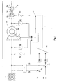
- Fig. 1 shows the schematic representation of a double-fed asynchronous machine with the associated control technology.
- the asynchronous machine 5 consists of a stator 5a and a rotor 5b. Furthermore, the asynchronous machine has a position sensor 5c.
- an inverter 6 is required for operation of the double-fed asynchronous machine.
- the inverter consists of a network-side converter 6a and a machine-side converter 6b.
- the network-side and the machine-side converter are connected to each other by a DC voltage intermediate circuit 6c.
- the machine-side converter 6b is connected via slip rings to the rotor 5b of the asynchronous machine.
- the stator 5a of the machine is connected to an electric grid 9 and the grid side converter 6a.
- the position sensor 5c includes an evaluation unit, not shown. As a result, both the rotor position and the rotor speed can be made available for the control. In alternative embodiments, rotor position and rotor speed can also be determined from the electrical quantities of the asynchronous machine, that is, without the use of a mechanical sensor.
- active power setpoint a setpoint for the delivered or to be received active power 1a
- target value for the dispensed or to be recorded Reactive power 1b referred to below as the reactive power setpoint
- the schematic representation shown is setpoint values for the active and reactive power delivered or absorbed to the network.
- the active power target value 1a and the negative real power actual value 2a are supplied to the adder 4a and give a target value deviation.
- the reactive power target value 1b and the negative reactive power actual value 2b for determining a target value deviation are supplied to the adder 4b.
- the corresponding target value deviations are supplied to the active power regulator 3a and the reactive power regulator 3b.
- the feedback unit is supplied with the stator voltage, the stator current and the rotor current, wherein the three-phase measured quantities are transformed by means of the transformation units 8a-c into a two-phase coordinate system.
- the two-phase coordinate system can be both a winding-resistant and a rotating coordinate system. Depending on the type of recycling only a part of these sizes is required.
- the speed of the machine is generally required for the return.
- the feedback unit 7 is passed the speed of the evaluation of the position sensor.
- the outputs of the power regulators 3a and 3b are applied to the output of the feedback unit by the adder 4c.
- the outputs of the power controllers are previously transformed into the corresponding coordinate system by means of the feedback unit 8e.
- Fig. 2 shows a schematic representation of a method according to the invention for determining the maximum allowable setpoints of the delivered or recorded active and reactive power.
- the active power setpoint 1a is set to limits the maximum allowable setpoint of the delivered or absorbed active power 10a.
- the limited active power setpoint then becomes, as in Fig. 1 shown, acted upon by the adder 4a with the negative actual value of the active power 2a and fed to the active power controller 3a.
- the reactive power setpoint 1 b is limited to the maximum permissible setpoint value of the delivered or recorded reactive power 10 b, applied to the negative actual value of the reactive power by means of the adder 4 b and fed to the reactive power controller 3 b.
- the maximum permissible setpoints for active and reactive power are determined by means of the current-limiting unit 10.
- the current limiting unit 10 can be given a priority active power or a reactive power priority. Regardless of the priority, a maximum permissible apparent power S max is calculated according to equation (1) by means of the current limiting unit.
- S Max 3 ⁇ U gene ⁇ w 21 ⁇ I red , Max ,
- U gene is the amount of the generator voltage 15 and I red, max the maximum allowable rotor current 16.
- the effective transmission ratio w 21 is a parameter of the simplified model.
- P 0 is the correction effective power 11a and Q 0 is the correction reactive power 11b, which are transferred from the correction unit 11 to the current-limiting unit 10.
- the actual value of the delivered or recorded active power 2a P is transferred from the power calculation module 2 to the current limiting unit 10.
- s is the slip 12, which must also be provided to the current limiting unit.
- the actual value of the delivered or recorded reactive power 2b Q is also added here, which is transferred from the power calculation module 2 to the current limiting unit 10 analogously to the active power actual value.
- the correction unit 11 the actual values of the delivered or recorded active power 2a and reactive power 2b are transferred to determine the correction active power 11a and the correction reactive power 11 b. Furthermore, the correction unit, the slip 12 and the actual values of the generator voltage 13 and the rotor current 14 are supplied. The operation of the correction unit is in the FIG. 3 and FIG. 4 shown in more detail.
- Fig. 3 shows a schematic representation of a method for determining the correction effective power 11a.
- the calculation unit 17a is supplied with the generator voltage 13, the rotor current 14 and the slip 12.
- the generator voltage and the rotor current are shown in a winding-fixed two-phase coordinate system.
- the generator voltage is thus described by the components, U gene , ⁇ and U gene , ⁇ .
- the rotor current consists of the components I Red , ⁇ and I Red , ⁇ .
- P model 1 - s ⁇ w 21 ⁇ U gene . ⁇ ⁇ I red . ⁇ + U gene . ⁇ ⁇ I red . ⁇
- the model active power P model forms the output of the calculation unit 17a.
- the model active power is applied by means of the adder 18a with the feedback correction active power 11a and gives an approximate value for the recorded or delivered active power.
- the approximate value and the effective power actual value 2a are supplied to the adaptation unit 19a and the correction effective power 11a is determined by means of an adaptation law.
- the adaptation process is realized by an adder 20a and a regulator 21a.
- the adder 20a determines the input value for the controller from the negative approximation value and the active power actual value.
- the output of the regulator 21a constitutes the correction active power 11a
- Fig. 4 shows a corresponding schematic representation of a method for determining the correction reactive power.
- the calculation unit 17b determines from the generator voltage 13 and the rotor current 14 a model reactive power Q model .
- the model reactive power is calculated according to equation (7).
- Q model ⁇ w 21 ⁇ - U gene . ⁇ ⁇ I red . ⁇ + U gene . ⁇ ⁇ I red . ⁇
- the model reactive power is applied to the feedback reactive reactive power and gives an approximate value for the recorded or delivered reactive power.
- the adder 20b determines a deviation from the negative approximate value and the reactive power actual value 2b the controller 21 b is supplied.
- the output of the regulator is the correction reactive power 11b.
- the adder 20b and the regulator 21b form the adaptation unit 19b.
- the described embodiment works reliably only when operating the double-fed asynchronous machine on a symmetrical three-phase network. However, it is possible to consider asymmetries. For this purpose, the measured quantities are split into the positive and negative systems.
- the protection concept can also be used with asymmetries in the electrical network.
- the method can also be used analogously to limit the stator current of the double-fed asynchronous machine. Furthermore, it can be used if the active and reactive power of the stator is regulated.
Landscapes
- Engineering & Computer Science (AREA)
- Power Engineering (AREA)
- Physics & Mathematics (AREA)
- General Physics & Mathematics (AREA)
- Chemical & Material Sciences (AREA)
- Combustion & Propulsion (AREA)
- Mechanical Engineering (AREA)
- General Engineering & Computer Science (AREA)
- Control Of Eletrric Generators (AREA)
- Control Of Electrical Variables (AREA)
- Supply And Distribution Of Alternating Current (AREA)
- Separation By Low-Temperature Treatments (AREA)
Abstract
Description
Die vorliegende Erfindung betrifft ein Verfahren sowie eine Vorrichtung zur Regelung der abgegebenen oder aufgenommenen Wirk- und Blindleistung einer doppeltgespeisten Asynchronmaschine, bei der der Strom der Maschine begrenzt werden soll.The present invention relates to a method and a device for controlling the delivered or recorded active and reactive power of a double-fed asynchronous machine, in which the current of the machine to be limited.
Die doppeltgespeiste Asynchronmaschine ist eine Asynchronmaschine, deren Stator im Allgemeinen mit einer Spannung konstanter Amplitude und Frequenz betrieben wird und beispielsweise mit einem elektrischen Netz verbunden ist. Der Rotor einer doppeltgespeisten Asynchronmaschine ist über Schleifringe elektrisch mit einem Umrichter, vorzugsweise einem Pulswechselrichter, verbunden. Dadurch kann im Rotor eine Spannung mit variabler Amplitude und Frequenz eingeprägt werden. Die doppeltgespeiste Asynchronmaschine ermöglicht den Betrieb mit konstanter Statorspannung bzw. Netzspannung und variabler Rotordrehzahl. Durch eine Steuereinheit kann der Umrichter so angesteuert werden, dass die von der doppeltgespeisten Asynchronmaschine abgegebene oder aufgenommene Wirk- und Blindleistung geregelt werden kann. Die doppeltgespeiste Asynchronmaschine wird beispielsweise in Windkraftanlagen hoher Leistung, als Wellengenerator oder in Verbindung mit Schwungmassenspeichem eingesetzt.The double-fed asynchronous machine is an asynchronous machine whose stator is generally operated at a voltage of constant amplitude and frequency and is connected, for example, to an electrical network. The rotor of a double-fed asynchronous machine is electrically connected via slip rings with a converter, preferably a pulse inverter. As a result, a voltage with variable amplitude and frequency can be impressed in the rotor. The double-fed asynchronous machine enables operation with constant stator voltage or mains voltage and variable rotor speed. By a control unit, the inverter can be controlled so that the output from the double-fed induction machine or recorded active and reactive power can be controlled. The double-fed asynchronous machine is used, for example, in wind turbines of high power, as a wave generator or in conjunction with flywheel mass memories.
Zum Schutz der Maschine und des Umrichters vor thermischer Überlastung darf ein maximal zulässiger Strom nicht überschritten werden. Dabei ist ein maximal zulässiger statischer und ein maximal zulässiger dynamischer Strom zu unterscheiden.To protect the machine and the inverter against thermal overload, a maximum permissible current must not be exceeded. A maximum permissible static and a maximum permissible dynamic current must be distinguished.
Der maximal zulässige statische Strom kann von verschiedenen Faktoren abhängen, z.B. von der Schlupffrequenz der Maschine, der Umgebungstemperatur oder der Schaltfrequenz des Umrichters. Der maximal zulässige statische Strom hängt aber auch von der Kühlung der Maschine und des Umrichters ab. Bei forcierter Luftkühlung durch einen separaten Lüfter kann der zulässige Strom auch von der Lüfterspannung, die im Allgemeinen der Netzspannung entspricht, abhängen.The maximum permissible static current can depend on various factors, eg the slip frequency of the machine, the ambient temperature or the switching frequency of the inverter. The maximum permissible static current depends but also from the cooling of the machine and the inverter. With forced air cooling by a separate fan, the allowable current may also depend on the fan voltage, which generally corresponds to the mains voltage.
Bei Systemen mit Dauerlast ist die Festlegung eines maximal zulässigen statischen Stromes ausreichend. Bei Systemen mit stetig wechselnden Lasten besteht im Allgemeinen die Anforderung, ein definiertes Lastspiel zuzulassen, um das System nicht für eine Dauerlast entsprechend der maximalen Kurzzeitlast auslegen zu müssen. Dabei wird kurzzeitig ein Strom oberhalb des zulässigen Dauerstroms zugelassen. Im Allgemeinen wird vereinfachend davon ausgegangen, dass die Verlustleistungen und damit die thermische Belastung des Systems proportional zum Quadrat des Stromes steigen. Um das System nicht zu überlasten, muss sichergestellt werden, dass der zeitliche Mittelwert des Quadrates des Stromes das Quadrat des maximal zulässigen Dauerstroms nicht übersteigt. Auf diese Weise wird ein maximal zulässiger dynamischer Strom definiert.For systems with continuous load, the determination of a maximum permissible static current is sufficient. In systems with constantly changing loads, there is generally a requirement to allow a defined load cycle so as not to have to design the system for a continuous load corresponding to the maximum short-term load. For a short time, a current above the permissible continuous current is allowed. In general, for the sake of simplification, it is assumed that the power losses and thus the thermal load of the system increase in proportion to the square of the current. In order not to overload the system, it must be ensured that the time average of the square of the current does not exceed the square of the maximum permissible continuous current. In this way, a maximum allowable dynamic current is defined.
Häufig wird zur Regelung der abgegebenen oder aufgenommenen Wirk- und Blindleistung einer doppeltgespeisten Asynchronmaschine eine Kaskadenstruktur der Regelung verwandt. Dabei gibt es jeweils einen Regler für Wirk- und Blindleistung. Die Ausgänge der Leistungsregler stellen die Sollwerte des Stromes für unterlagerte Stromregler dar. Die Sollwerte des Stromes werden mit den Istwerten verglichen. Die Differenzsignale bilden den Eingang für die unterlagerten Stromregler. Die Begrenzung des Stromes auf einen maximal zulässigen Wert, sei es nun ein maximal zulässiger statischer oder maximal zulässiger dynamischer Stromwert, kann bei einer solchen Anordnung sehr einfach durch Begrenzung der Ausgänge der Wirk- und Blindleistungsregler durchgeführt werden. Eine solche Regelstruktur hat jedoch deutliche Nachteile: Durch die Kaskadenstruktur mit den unterlagerten Stromreglern müssen Einschränkungen hinsichtlich der Dynamik hingenommen werden. Durch bestimmte Reglerstrukturen kann die Dynamik zwar verbessert werden, solche Reglerstrukturen stellen jedoch hohe Anforderungen an den Parameterabgleich. Nur eine sorgfältig auf die jeweilige Anlage abgestimmte Reglerstruktur kann die Dynamik der Regelung verbessern.Often, a cascade structure of the control is used to control the delivered or recorded active and reactive power of a double-fed asynchronous machine. There is one controller each for active and reactive power. The outputs of the power controllers represent the setpoint values of the current for subordinate current controllers. The setpoint values of the current are compared with the actual values. The differential signals form the input for the subordinate current controllers. The limitation of the current to a maximum permissible value, be it a maximum permissible static or maximum permissible dynamic current value, can be carried out very simply by limiting the outputs of the active power and reactive power controllers in such an arrangement. However, such a rule structure has significant disadvantages: Due to the cascade structure with the subordinate current regulators, restrictions in terms of dynamics must be accepted. Certain dynamics can be improved by certain controller structures, but such controller structures place high demands on the parameter adjustment. Only a control structure carefully matched to the respective system can improve the dynamics of the control.
Aus der
Aus der
Aufgrund der oben beschriebenen Nachteile ist bei hochdynamischen Anforderungen ein Verzicht auf unterlagerte Stromregler anzustreben.Due to the disadvantages described above, it is desirable to dispense with lower-level current controllers in the case of highly dynamic requirements.
Hierzu ist es grundsätzlich denkbar, den Strom indirekt zu begrenzen, und zwar durch Begrenzung der Sollwerte der abgegebenen oder aufgenommenen Wirk- und Blindleistung. Hierzu wäre es denkbar, eine Kennlinie mit maximal zulässigen Sollwerten der abgegebenen oder aufgenommenen Wirk- und Blindleistung in Abhängigkeit von verschiedenen Einflussgrößen zu ermitteln und einzusetzen. Solche Einflussgrößen könnten zum Beispiel Spannung, Frequenz oder Drehzahl sein. Die vielen sonstigen Einflussgrößen würden allerdings unvermeidbar zu relativ großen Ungenauigkeiten der vorausberechneten Kennlinien führen. Dies hätte zur Folge, dass die Ströme in vielen Betriebszuständen stärker beschränkt werden müssten, als es zum Schutz der Anlage eigentlich erforderlich wäre. Der Umrichter und die Maschine müssten also bei einem solchen Schutzkonzept für eine entsprechend höhere Leistung ausgelegt werden, um eine Einhaltung der zulässigen Werte stets zu gewährleisten; eine derartige permanente Einhaltung der zulässigen Werte ist jedoch unverzichtbar.For this purpose, it is conceivable in principle to limit the current indirectly, by limiting the setpoints of the delivered or recorded active and reactive power. For this purpose, it would be conceivable to determine and use a characteristic curve with maximum permissible setpoint values of the delivered or recorded active and reactive power as a function of different influencing variables. Such factors could be, for example, voltage, frequency or speed. However, the many other factors would inevitably lead to relatively large inaccuracies of the predicted characteristics. This would mean that in many operating conditions the currents would have to be restricted more than would actually be required to protect the system. The converter and the machine would therefore have to be designed with such a protection concept for a correspondingly higher power in order to always ensure compliance with the permissible values; however, such permanent compliance with the permissible values is indispensable.
Es ist daher die Aufgabe der vorliegenden Erfindung, den Strom einer doppeltgespeisten Asynchronmaschine, deren abgegebene oder aufgenommene Wirk- und Blindleistung geregelt wird, zuverlässig so zu begrenzen, dass die Dynamik der Leistungsregelung nicht beeinflusst wird und die Anlage für eine möglichst kleine Leistung ausgelegt werden kann.It is therefore an object of the present invention to reliably control the current of a double-fed asynchronous machine whose delivered or recorded active and reactive power is limited so that the dynamics of the power control is not affected and the system can be designed for the lowest possible power ,
Zur Lösung der vorstehend genannten Aufgabe wird ein Verfahren mit den Merkmalen des Patentanspruches 1 sowie eine Vorrichtung mit den Merkmalen des Patentanspruchs 14 vorgeschlagen.To solve the above object, a method having the features of claim 1 and a device having the features of
Vorteilhafte Ausgestaltungen der Erfindung sind in den abhängigen Patentansprüchen beschrieben.Advantageous embodiments of the invention are described in the dependent claims.
Zur Lösung der genannten Aufgabe wird ein Verfahren zur Begrenzung eines Stromes einer doppeltgespeisten Asynchronmaschine vorgeschlagen, wobei die abgegebene oder aufgenommene Wirk- und Blindleistung der doppeltgespeisten Asynchronmaschine geregelt wird, und wobei während des Betriebes der doppeltgespeisten Asynchronmaschine ein maximal zulässiger Sollwert der abzugebenden oder aufzunehmenden Wirkleistung und ein maximal zulässiger Sollwert der abzugebenden oder aufzunehmenden Blindleistung unter Zuhilfenahme eines Modells der Asynchronmaschine aus dem maximal zulässigen Strom derart bestimmt werden, dass dieser nicht überschritten wird, und wobei die vorgegebenen Wirk- und Blindleistungssollwerte auf die berechneten maximal zulässigen Werte begrenzt werden.To solve the above problem, a method for limiting a current of a double-fed asynchronous machine is proposed, wherein the delivered or recorded active and reactive power of the double-fed asynchronous machine is controlled, and wherein during operation of the double-fed asynchronous machine, a maximum allowable target value to be delivered or absorbed active power and A maximum allowable setpoint value of the reactive power to be delivered or received is determined from the maximum permissible current with the aid of a model of the asynchronous machine in such a way that it is not exceeded, and the predetermined effective and reactive power setpoint values are limited to the calculated maximum permissible values.
Bei der erfindungsgemäßen Lösung sind also keine unterlagerten Stromregler mehr erforderlich, da die Sollwerte der abgegebenen oder aufgenommenen Wirk- und Blindleistung begrenzt werden und die Strombegrenzung somit indirekt durchgeführt wird. Im Gegensatz zu einer vorstehend erörterten Kennlinienlösung werden die maximalen zulässigen Sollwerte der abgegebenen oder aufgenommenen Wirk- und Blindleistung nicht im Voraus berechnet, sondern während des Betriebes der doppeltgespeisten Asynchronmaschine - vorzugsweise unter Verwendung einer geeigneten Rückführung - berechnet. Dadurch können die maximal zulässigen Sollwerte der abzugebenden oder aufzunehmenden Wirk- und Blindleistung individuell für den jeweiligen Arbeitspunkt bestimmt werden.In the solution according to the invention, therefore, no subordinate current regulators are required any more since the setpoint values of the delivered or recorded active and reactive power are limited and the current limitation is thus carried out indirectly. In contrast to a characteristic solution discussed above For example, the maximum allowable setpoints of the delivered or ingested active and reactive power are not calculated in advance but are calculated during operation of the double-fed asynchronous machine, preferably using a suitable feedback. As a result, the maximum permissible setpoint values of the effective and reactive power to be delivered or absorbed can be determined individually for the respective operating point.
In einer bevorzugten Ausführungsform der Erfindung wird bei der Berechnung der maximal zulässigen Sollwerte für die Wirk- und Blindleistung wenigstens der Istwert des zu begrenzenden Stromes zur Korrektur herangezogen.In a preferred embodiment of the invention, at least the actual value of the current to be limited is used for the correction in the calculation of the maximum permissible setpoint values for the active and reactive power.
Gemäß der Erfindung wird bei Angabe einer Priorität Wirkleistung zuerst der maximal zulässige Sollwert der abzugebenden oder aufzunehmenden Wirkleistung bestimmt, und der maximal zulässige Sollwert der abzugebenden oder aufzunehmenden Blindleistung wird in Abhängigkeit des Sollwertes der abzugebenden oder aufzunehmenden Wirkleistung bestimmt. Bei Angabe einer Priorität Blindleistung wird zuerst der maximal zulässige Sollwert der abzugebenden oder aufzunehmenden Blindleistung bestimmt und der maximal zulässige Sollwert der abzugebenden oder aufzunehmenden Wirkleistung wird inAccording to the invention, when specifying a priority active power, first the maximum allowable setpoint of the active power to be delivered or received is determined, and the maximum allowable setpoint of the reactive power to be delivered or received is determined in dependence on the setpoint of the active power to be delivered or received. If a reactive power priority is specified, the maximum permissible setpoint value of the reactive power to be delivered or recorded is determined first, and the maximum permissible setpoint value of the active power to be delivered or absorbed is determined in
Abhängigkeit des maximal zulässigen Sollwertes der abzugebenden oder aufzunehmenden Blindleistung bestimmt.Dependence of the maximum permissible nominal value of the reactive power to be delivered or to be recorded.
Bei Angabe einer Priorität Wirkleistung wird vorrangig Wirkleistung produziert, das heißt die Blindleistung wird zuerst reduziert. Diese Priorität wird z.B. zur Triebstrangdämpfung vorgegeben. Bei Angabe einer Priorität Blindleistung wird vorrangig Blindleistung produziert, das heißt die Wirkleistung wird bei zu hohem Strom zuerst reduziert. Eine Priorität Blindleistung wird z. B. zur Spannungsstützung angegeben.If an active power priority is specified, active power is primarily produced, ie the reactive power is reduced first. This priority is e.g. specified for driveline damping. If a reactive power priority is specified, reactive power is primarily produced, ie the active power is first reduced if the current is too high. A priority reactive power is z. B. specified for voltage support.
Die Angabe einer Priorität Wirk- oder Blindleistung ermöglicht in vorteilhafter Weise die Anpassung der Anlage mit doppeltgespeister Asynchronmaschine an die jeweiligen Bedingungen.The specification of a priority effective or reactive power allows the adaptation of the system with double-fed asynchronous machine to the respective conditions in an advantageous manner.
Gemäß einer weiteren bevorzugten Ausführungsform der vorliegenden Erfindung wird mittels eines vereinfachten Modells der doppeltgespeisten Asynchronmaschine aus dem maximal zulässigen Strom eine maximal zulässige Scheinleistung ermittelt.According to a further preferred embodiment of the present invention, a maximum permissible apparent power is determined from the maximum permissible current by means of a simplified model of the double-fed asynchronous machine.
Zum thermischen Schutz der doppeltgespeisten Asynchronmaschine und des dazugehörigen Umrichters ist die Begrenzung des Betrages des Stromes erforderlich. Es ist dabei unerheblich, ob es sich um einen Wirk- oder um einen Blindstrom handelt. Damit stellt der maximal zulässige Strom einen Scheinstrom dar. Es ist somit besonders einfach, unter Verwendung eines vereinfachten Modells aus dem maximal zulässigen Scheinstrom eine maximal zulässige Scheinleistung zu ermitteln. Eine solche Ausführungsform ist besonders universell. Sie ist unabhängig davon anwendbar, ob eine Priorität Wirkleistung oder eine Priorität Blindleistung angegeben wird, oder ob ein bestimmtes Verhältnis von Wirk- und Blindleistung, das heißt ein Leistungsfaktor, vorgegeben wird.For the thermal protection of the double-fed asynchronous machine and the associated inverter limiting the amount of current is required. It is irrelevant whether it is an active or a reactive current. Thus, the maximum allowable current is a dummy current. It is thus particularly easy to determine a maximum allowable apparent power from the maximum permissible apparent current using a simplified model. Such an embodiment is particularly universal. It is applicable irrespective of whether a priority is given to active power or a reactive power priority, or whether a specific ratio of active power and reactive power, that is to say a power factor, is specified.
Gemäß einer weiteren bevorzugten Ausführungsform der vorliegenden Erfindung wird bei Angabe einer Priorität Wirkleistung der maximal zulässige Sollwert der abzugebenden oder aufzunehmenden Wirkleistung aus der maximal zulässigen Scheinleistung und einer Korrekturwirkleistung bestimmt, und der maximal zulässige Sollwert der abzugebenden oder aufzunehmenden Blindleistung wird aus dem Istwert der abgegebenen oder aufgenommenen Wirkleistung, der Korrekturwirkleistung und einer Korrekturblindleistung bestimmt.In accordance with a further preferred embodiment of the present invention, when a priority active power is specified, the maximum permissible setpoint value of the active power to be delivered or to be received is determined from the maximum permissible value Apparent power and a correction effective power determined, and the maximum allowable setpoint of the reactive power to be delivered or received is determined from the actual value of the delivered or recorded active power, the correction effective power and a correction reactive power.
Die maximal zulässige Scheinleistung wird mittels eines vereinfachten Modells bestimmt. Aus diesem Grunde kann in der Realität die maximal zulässige Scheinleistung sowohl nach oben oder unten abweichen. Deshalb sollte bei Angabe einer Priorität Wirkleistung der maximal zulässige Sollwert der abzugebenden oder aufzunehmenden Wirkleistung nicht allein aus maximal zulässigen Scheinleistung ermittelt werden, vielmehr ist es besonders vorteilhaft, die maximal zulässige Scheinleistung mit einer Korrekturwirkleistung zu beaufschlagen. Bei Angabe einer Priorität Wirkleistung wird nun zur optimalen Ausnutzung der Anlage der maximal zulässige Sollwert der abzugebenden oder aufzunehmenden Blindleistung in vorteilhafter Weise so bestimmt, dass unter Berücksichtung der Korrekturwerte für Wirk- und Blindleistung die maximal zulässige Scheinleistung nicht überschritten wird. Insofern wird klar, dass zur Ermittlung des maximal zulässigen Sollwertes der abgegebenen oder aufgenommenen Blindleistung der Istwert der abzugebenden oder aufzunehmenden Wirkleistung berücksichtigt wird.The maximum allowable apparent power is determined using a simplified model. For this reason, in reality, the maximum allowable apparent power may vary both upwards or downwards. Therefore, when specifying a priority active power, the maximum allowable setpoint of the active power to be delivered or absorbed should not be determined solely from the maximum permissible apparent power, but it is particularly advantageous to apply a correction effective power to the maximum permissible apparent power. If an active power priority is specified, the maximum permissible setpoint value of the reactive power to be emitted or absorbed is now advantageously determined in such a way that the maximum permissible apparent power is not exceeded taking into account the correction values for active power and reactive power. In this respect, it is clear that the actual value of the active power to be delivered or absorbed is taken into account in order to determine the maximum permissible setpoint value of the delivered or recorded reactive power.
Gemäß einer weiteren bevorzugten Ausführungsform der vorliegenden Erfindung wird bei Angabe einer Priorität Blindleistung der maximal zulässige Sollwert der abzugebenden oder aufzunehmenden Blindleistung aus der maximal zulässigen Scheinleistung und einer Korrekturblindleistung bestimmt und der maximal zulässige Sollwert der abzugebenden oder aufzunehmenden Wirkleistung wird aus dem Istwert der abgegebenen oder aufgenommenen Blindleistung, der Korrekturblindleistung und einer Korrekturwirkleistung bestimmt.In accordance with a further preferred embodiment of the present invention, when a reactive power priority is specified, the maximum permissible setpoint value of the reactive power to be emitted or received is determined from the maximum permissible apparent power and a correction reactive power, and the maximum permissible setpoint value of the active power to be delivered or absorbed is determined from the actual value of the delivered or recorded actual power Reactive power, the correction reactive power and a correction effective power determined.
Gemäß einer weiteren bevorzugten Ausführungsform der vorliegenden Erfindung wird die Korrekturwirkleistung mittels eines Adaptionsgesetzes aus dem Istwert und einem Näherungswert für die aufgenommene oder abgegebene Wirkleistung bestimmt, wobei der Näherungswert aus der Summe der rückgekoppelten Korrekturwirkleistung und einer Wirkleistung, die mittels des vereinfachten Modells der doppeltgespeisten Asynchronmaschine ermittelt wird, besteht.According to a further preferred embodiment of the present invention, the correction effective power is determined by means of an adaptation law from the actual value and an approximate value for the recorded or delivered active power, wherein the approximation value from the sum of the feedback correction active power and an active power, which is determined by means of the simplified model of the double-fed asynchronous machine consists.
Gemäß einer weiteren bevorzugten Ausführungsform der vorliegenden Erfindung wird die Korrekturblindleistung mittels eines Adaptionsgesetzes aus dem Istwert und einem Näherungswert für die aufgenommene oder abgegebene Blindleistung bestimmt, wobei der Näherungswert aus der Summe der rückgekoppelten Korrekturblindleistung und einer Blindleistung, die mittels des vereinfachten Modells der doppeltgespeisten Asynchronmaschine ermittelt wird, besteht.According to a further preferred embodiment of the present invention, the correction reactive power is determined by means of an adaptation law from the actual value and an approximate value for the recorded or emitted reactive power, wherein the approximate value of the sum of the feedback reactive reactive power and a reactive power determined by means of the simplified model of the double-fed induction machine will exist.
Die Ermittlung der Korrekturwerte für Wirk- und Blindleistung erfolgt also vorzugsweise mit einem Beobachter. Der Beobachter besteht aus einem einfachen Modell mit einer geeigneten Rückführung, die dafür sorgt, dass die Näherungswerte mit den gemessenen Systemgrößen in Übereinstimmung gebracht werden. Diese Übereinstimmung wird anhand eines Adaptionsgesetzes erreicht. Das Adaptionsgesetz muss so gewählt werden, das der Adaptionsvorgang stabil erfolgt. Eine einfache Umsetzung für ein Adaptionsgesetz ist die Auswertung der Differenz aus Näherungswert und Istwert durch einen Regler oder einen Filter. Die Systemgrößen des Beobachters sind Wirk- und Blindleistung. Das vereinfachte Modell berechnet aus dem Istwert des zu begrenzenden Stromes und der Spannung eine Modellwirk- und -blindleistung. Die Rückführung addiert hierzu einen Korrekturwert für Wirkleistung oder Blindleistung derart, dass diese Summe in Übereinstimmung mit der zu regelnden abzugebenden oder aufzunehmenden Wirk- und Blindleistung gebracht wird.The determination of the correction values for active power and reactive power thus preferably takes place with an observer. The observer consists of a simple model with a suitable feedback, which ensures that the approximate values are matched with the measured system quantities. This agreement is achieved by means of an adaptation law. The adaptation law must be chosen so that the adaptation process is stable. A simple implementation for an adaptation law is the evaluation of the difference between the approximate value and the actual value by a controller or a filter. The system variables of the observer are active and reactive power. The simplified model calculates a model effective and reactive power from the actual value of the current to be limited and the voltage. For this purpose, the feedback adds a correction value for active power or reactive power in such a way that this sum is brought into conformity with the active and reactive power to be delivered or to be transmitted.
Im Allgemeinen wird davon ausgegangen, dass die doppeltgespeiste Asynchronmaschine an einem symmetrischen Dreiphasennetz betrieben wird. Dies ist in der Praxis jedoch nicht immer gegeben. Durch Unsymmetrien tritt in Spannungen und Strömen neben dem Mitsystem auch ein Gegensystem auf. Die gemessenen Ströme und Spannungen, die für die Regelung der abzugebenden oder aufzunehmenden Wirk- und Blindleistung oder zur Durchführung der Strombegrenzung erforderlich sind, können mit Hilfe bekannter Verfahren in Mit- und Gegensystem zerlegt werden. Solche Verfahren können z.B. der Dissertation von H. Wrede, "Beiträge zur Erhöhung von Versorgungssicherheit und Spannungsqualität in der Übertragung und Verteilung elektrischer Energie durch leistungselektronische Betriebsmittel", erschienen 2004 im Shaker Verlag, entnommen werden.In general, it is assumed that the double-fed asynchronous machine is operated on a symmetrical three-phase network. However, this is not always the case in practice. Due to asymmetries in tensions and currents in addition to the co-system also a negative sequence occurs. The measured currents and voltages, which are required for the control of the active and reactive power to be delivered or absorbed, or for carrying out the current limitation, can be decomposed by means of known methods in the positive and negative sequence. Such methods can be found eg in the dissertation by H. Wrede, "Contributions to increase security of supply and voltage quality in the transmission and distribution of electrical energy by power electronic equipment", published in 2004 by Shaker Verlag, are taken.
Die Gegensystemkomponente des Stromes führt zu einer zusätzlichen thermischen Belastung, so dass gemäß einer weiteren bevorzugten Ausführungsform der vorliegenden Erfindung die maximal zulässige Scheinleistung aus Mitsystemgrößen bestimmt wird, und die maximal zulässige Mitsystemkomponente des Stromes durch Verminderung des maximal zulässigen Stromes um die Gegensystemkomponente des Strom-Istwertes bestimmt wird.The negative sequence component of the current leads to an additional thermal load, so that according to a further preferred embodiment of the present invention, the maximum permissible apparent power is determined from Mitsystemgrößen, and the maximum permissible Mitsystemkomponente the current by reducing the maximum allowable current to the negative sequence component of the current value is determined.
Gemäß einer weiteren bevorzugten Ausführungsform der vorliegenden Erfindung wird anstelle des Istwertes der abgegebenen oder aufgenommenen Wirkleistung der Istwert der abgegeben oder aufgenommenen Mitsystemwirkleistung und anstelle des Istwertes der abgegebenen oder aufgenommenen Blindleistung der Istwert der abgegeben oder aufgenommenen Mitsystemblindleistung verwendet.According to a further preferred embodiment of the present invention, instead of the actual value of the delivered or recorded active power, the actual value of the delivered or recorded co-reactive power and instead of the actual value of the delivered or recorded reactive power, the actual value of the delivered or recorded Mitsystemsblindleistung.
Die Gesamtleistung der Grundschwingungsanteile für ein System ohne Sternpunkterdung setzt sich aus der Summe von vier Produkten zusammen, nämlich dem Produkt aus den Mitsystemkomponenten von Strom und Spannung, dem Produkt aus den Gegensystemkomponenten von Strom und Spannung, dem Produkt aus der Mitsystemkomponente der Spannung und der Gegensystemkomponente des Stromes sowie dem Produkt aus der Gegensystemkomponente der Spannung und der Gegensystemkomponente des Stromes. Insbesondere die Produkte aus Mit- und Gegensystemkomponenten können bei der Leistungsregelung und Strombegrenzung zu Problemen führen, da sich hieraus Wechselleistungen ergeben. Bei einer Grundschwingungsfrequenz von 50 Hz haben diese Wechselleistungen eine Frequenz von 100 Hz. Die Produkte, die nur aus Gegensystem- bzw. Mitsystemkomponenten gebildet werden, ergeben dagegen im stationären Fall Gleichgrößen. Die Mitsystemleistung wird berechnet, indem die Gesamtleistung um die Produkte aus Mit- und Gegensystemkomponenten und dem Produkt aus den Gegensystemkomponenten reduziert wird.The total power of the fundamental components for a non-neutral system consists of the sum of four products, namely the product of the co-system components of current and voltage, the product of the negative sequence components of current and voltage, the product of the co-system component of the voltage and the negative sequence component the current and the product of the negative sequence component of the voltage and the negative sequence component of the current. In particular, the products of positive and negative sequence components can lead to problems in the power control and current limitation, since this results in alternating power. At a fundamental frequency of 50 Hz, these alternating powers have a frequency of 100 Hz. On the other hand, the products which are formed only of negative-sequence or positive-sequence components produce equal quantities in the stationary case. The co-system performance is calculated by reducing the total power by the products of the co-and negative sequence components and the product of the negative sequence components.
Gemäß einer weiteren bevorzugten Ausführungsform der vorliegenden Erfindung werden zur Ermittlung der Wirkleistung und der Blindleistung mittels des vereinfachten Modells der doppeltgespeisten Asynchronmaschine Mitsystemgrößen verwendet.In accordance with another preferred embodiment of the present invention, system sizes are used to determine real power and reactive power using the simplified model of the double-fed asynchronous machine.
Gemäß einer weiteren bevorzugten Ausführungsform der vorliegenden Erfindung wird der Rotorstrom der doppeltgespeisten Asynchronmaschine begrenzt.According to another preferred embodiment of the present invention, the rotor current of the double-fed asynchronous machine is limited.
Gemäß einer weiteren bevorzugten Ausführungsform der vorliegenden Erfindung wird der Statorstrom der doppeltgespeisten Asynchronmaschine begrenzt.According to another preferred embodiment of the present invention, the stator current of the double-fed asynchronous machine is limited.
Gemäß einer weiteren bevorzugten Ausführungsform der vorliegenden Erfindung wird die Wirk- und Blindleistung des Stators der doppeltgespeisten Asynchronmaschine geregelt.According to a further preferred embodiment of the present invention, the active and reactive power of the stator of the double-fed asynchronous machine is controlled.
Gemäß einer weiteren bevorzugten Ausführungsform der vorliegenden Erfindung wird die Wirk- und Blindleistung des Netzes, an das die doppeltgespeiste Asynchronmaschine angeschlossen ist, geregelt.According to a further preferred embodiment of the present invention, the active and reactive power of the network to which the double-fed asynchronous machine is connected, regulated.
Zur Lösung der Aufgabe wird ferner eine Vorrichtung zur Regelung der abgegebenen oder aufgenommenen Wirk- und Blindleistung einer doppeltgespeisten Asynchronmaschine vorgeschlagen, wobei die Vorrichtung Mittel zur Begrenzung eines Stromes der doppeltgespeisten Asynchronmaschine umfasst, dadurch gekennzeichnet, dass durch die Mittel während des Betriebes der doppeltgespeisten Asynchronmaschine ein maximal zulässiger Sollwert der abzugebenden oder aufzunehmenden Wirkleistung und ein maximal zulässiger Sollwert der abzugebenden oder aufzunehmenden Blindleistung anhand eines Modells der Asynchronmaschine aus einem maximal zulässigen Strom derart bestimmt werden, dass dieser nicht überschritten wird.To solve the problem, a device for controlling the delivered or recorded active and reactive power of a double-fed asynchronous machine is also proposed, wherein the device comprises means for limiting a current of the double-fed asynchronous machine, characterized in that by the means during operation of the double-fed asynchronous machine Maximum permissible setpoint value of the active power to be delivered or absorbed and a maximum permissible setpoint value of the reactive power to be emitted or absorbed are determined on the basis of a model of the asynchronous machine from a maximum permissible current such that it is not exceeded.
Die Vorrichtung gemäß der vorliegenden Erfindung kann beispielsweise ein Steuergerät zur Ansteuerung des Umrichters sein, das mit Schnittstellen zur Aufnahme von Messwerten und Sollwertvorgaben ausgestattet ist und einen oder mehrere Mikrocontroller zur Auswertung der Schnittstellensignale und Ausführung der Regelung aufweist.The device according to the present invention can be, for example, a control device for controlling the converter, which is equipped with interfaces for receiving measured values and setpoint specifications and one or more Having microcontroller for evaluation of the interface signals and execution of the control.
Gemäß der Erfindung umfasst die Vorrichtung Mittel zur Angabe einer Priorität, wobei bei Angabe einer Priorität Wirkleistung zuerst der maximal zulässige Sollwert der abzugebenden oder aufzunehmenden Wirkleistung und der maximal zulässige Sollwert der abzugebenden oder aufzunehmenden Blindleistung in Abhängigkeit des Sollwertes der abzugebenden oder aufzunehmenden Wirkleistung durch die Mittel bestimmt wird, und wobei bei Angabe einer Priorität Blindleistung zuerst der maximal zulässige Sollwert der abzugebenden oder aufzunehmenden Blindleistung und der maximal zulässige Sollwert der abzugebenden oder aufzunehmenden Wirkleistung in Abhängigkeit des maximal zulässigen Sollwertes der abzugebenden oder aufzunehmenden Blindleistung durch die Mittel bestimmt wird.According to the invention, the device comprises means for indicating a priority, wherein upon specification of a priority active power first the maximum allowable setpoint of the active power to be delivered or to be delivered and the maximum allowable setpoint of the reactive power to be delivered or received depending on the setpoint of the delivered or absorbed active power by the means is determined, and given a priority reactive power first the maximum allowable setpoint of the reactive power to be delivered or recorded and the maximum allowable setpoint of the active power to be delivered or received depending on the maximum allowable setpoint of the reactive power to be delivered or to be determined by the means.
Gemäß einer weiteren bevorzugten Ausführungsform der vorliegenden Erfindung ermitteln die Mittel unter Verwendung eines vereinfachten Modells der doppeltgespeisten Asynchronmaschine aus dem maximal zulässigen Strom eine maximal zulässige Scheinleistung.According to another preferred embodiment of the present invention, the means determines a maximum allowable apparent power from the maximum allowable current using a simplified model of the double-fed asynchronous machine.
Gemäß einer weiteren bevorzugten Ausführungsform der vorliegenden Erfindung wird bei Angabe einer Priorität Wirkleistung der maximal zulässige Sollwert der abzugebenden oder aufzunehmenden Wirkleistung aus der maximal zulässigen Scheinleistung und einer Korrekturwirkleistung durch die Mittel bestimmt und der maximal zulässige Sollwert der abzugebenden oder aufzunehmenden Blindleistung wird aus dem Istwert der abgegebenen oder aufgenommenen Wirkleistung, der Korrekturwirkleistung und einer Korrekturblindleistung durch die Mittel bestimmt.According to a further preferred embodiment of the present invention, when specifying a priority active power, the maximum allowable setpoint of the active power to be delivered or received from the maximum allowable apparent power and a correction active power determined by the means and the maximum allowable setpoint of the reactive power to be delivered or received from the actual value of the delivered or recorded active power, the correction effective power and a correction reactive power determined by the means.
Gemäß einer weiteren bevorzugten Ausführungsform der vorliegenden Erfindung wird bei Angabe einer Priorität Blindleistung der maximal zulässige Sollwert der abzugebenden oder aufzunehmenden Blindleistung aus der maximal zulässigen Scheinleistung und einer Korrekturblindleistung durch die Mittel bestimmt, und der maximal zulässige Sollwert der abzugebenden oder aufzunehmenden Wirkleistung wird aus dem Istwert der abgegebenen oder aufgenommenen Blindleistung, der Korrekturblindleistung und einer Korrekturwirkleistung durch die Mittel bestimmt.In accordance with a further preferred embodiment of the present invention, when a reactive power priority is specified, the maximum permissible setpoint value of the reactive power to be emitted or received is determined from the maximum permissible apparent power and a correction reactive power by the means, and the maximum permissible setpoint value of the active power to be delivered or absorbed is determined from the actual value of the delivered or recorded reactive power, the correction reactive power and a correction active power by the means.
Gemäß einer weiteren bevorzugten Ausführungsform der vorliegenden Erfindung wird die Korrekturwirkleistung mittels einer Adaptionseinheit aus dem Istwert und einem Näherungswert für die aufgenommene oder abgegebene Wirkleistung bestimmt, wobei der Näherungswert aus der Summe der rückgekoppelten Korrekturwirkleistung und einer Wirkleistung, die durch die Mittel unter Verwendung des vereinfachten Modells der doppeltgespeisten Asynchronmaschine berechnet wird, besteht.According to a further preferred embodiment of the present invention, the correction effective power is determined by means of an adaptation unit from the actual value and an approximate value for the absorbed or delivered active power, wherein the approximation value of the sum of the feedback correction active power and an active power, by the means using the simplified model the double-fed asynchronous machine is calculated.
Gemäß einer weiteren bevorzugten Ausführungsform der vorliegenden Erfindung wird die Korrekturblindleistung mittels einer Adaptionseinheit aus dem Istwert und einem Näherungswert für die aufgenommene oder abgegebene Blindleistung bestimmt, wobei der Näherungswert aus der Summe der rückgekoppelten Korrekturblindleistung und einer Blindleistung, die durch die Mittel unter Verwendung des vereinfachten Modells der doppeltgespeisten Asynchronmaschine berechnet wird, besteht.According to a further preferred embodiment of the present invention, the correction reactive power is determined by means of an adaptation unit from the actual value and an approximate value for the recorded or delivered reactive power, the approximate value being the sum of the feedback reactive reactive power and reactive power generated by the means using the simplified model the double-fed asynchronous machine is calculated.
Gemäß einer weiteren bevorzugten Ausführungsform der vorliegenden Erfindung wird die maximal zulässige Scheinleistung durch die Mittel aus Mitsystemgrößen bestimmt und die maximal zulässige Mitsystemkomponente des Stromes wird durch Mittel zur Verminderung des maximal zulässigen Stromes um die Gegensystemkomponente des Strom-Istwertes bestimmt.According to a further preferred embodiment of the present invention, the maximum permissible apparent power is determined by the means of Mitsystemgrößen and the maximum allowable Mitsystemkomponente the current is determined by means for reducing the maximum allowable current to the negative sequence component of the current actual value.
Gemäß einer weiteren bevorzugten Ausführungsform der vorliegenden Erfindung verwenden die Mittel anstelle des Istwertes der abgegebenen oder aufgenommenen Wirkleistung den Istwert der abgegeben oder aufgenommenen Mitsystemwirkleistung und anstelle des Istwertes der abgegebenen oder aufgenommenen Blindleistung den Istwert der abgegeben oder aufgenommenen Mitsystemblindleistung. Gemäß einer weiteren bevorzugten Ausführungsform der vorliegenden Erfindung verwenden die Mittel zur Berechnung der Wirkleistung und der Blindleistung unter Verwendung des vereinfachten Modells der doppeltgespeisten Asynchronmaschine Mitsystemgrößen.According to a further preferred embodiment of the present invention, the means instead of the actual value of the delivered or recorded active power the actual value of the delivered or recorded Mitsystemwirkleistung and instead of the actual value of the delivered or recorded reactive power the actual value of the delivered or recorded Mitsystemsblindleistung. According to another preferred embodiment of the present invention, the means for calculating the active power and the reactive power using the simplified model of the double-fed asynchronous machine Mitsystemgrößen.
Gemäß einer weiteren bevorzugten Ausführungsform der vorliegenden Erfindung wird der Rotorstrom der doppeltgespeisten Asynchronmaschine begrenzt.According to another preferred embodiment of the present invention, the rotor current of the double-fed asynchronous machine is limited.
Gemäß einer weiteren bevorzugten Ausführungsform der vorliegenden Erfindung wird der Statorstrom der doppeltgespeisten Asynchronmaschine begrenzt.According to another preferred embodiment of the present invention, the stator current of the double-fed asynchronous machine is limited.
Gemäß einer weiteren bevorzugten Ausführungsform der vorliegenden Erfindung wird die Wirk- und Blindleistung des Stators der doppeltgespeisten Asynchronmaschine geregelt.According to a further preferred embodiment of the present invention, the active and reactive power of the stator of the double-fed asynchronous machine is controlled.
Gemäß einer weiteren bevorzugten Ausführungsform der vorliegenden Erfindung wird die Wirk- und Blindleistung des Netzes, an das die doppeltgespeiste Asynchronmaschine angeschlossen ist, geregelt.According to a further preferred embodiment of the present invention, the active and reactive power of the network to which the double-fed asynchronous machine is connected, regulated.
Im Folgenden wird ein Ausführungsbeispiel der vorliegenden Erfindung unter Bezugnahme auf die Zeichnungen näher erläutert.In the following, an embodiment of the present invention will be explained in more detail with reference to the drawings.
Es zeigen:
- Fig. 1:
- eine schematische Darstellung einer Regelstruktur zur Regelung der abge- gebenen oder aufgenommenen Wirk- und Blindleistung der doppeltgespeis- ten Asynchronmaschine ohne unterlagerte Stromregler;
- Fig. 2:
- eine schematische Darstellung eines erfindungsgemäßen Verfahrens zur Bestimmung der maximal zulässigen Sollwerte der abzugebenden oder auf- zunehmenden Wirk- und Blindleistung;
- Fig. 3:
- eine schematische Darstellung eines Verfahrens zur Ermittlung der Korrek- turwirkleistung;
- Fig. 4:
- eine schematische Darstellung eines Verfahrens zur Ermittlung der Korrek- turblindleistung;
- Fig. 1:
- a schematic representation of a control structure for controlling the delivered or recorded active and reactive power of the double-fed asynchronous machine without subordinate current controller;
- Fig. 2:
- a schematic representation of a method according to the invention for determining the maximum allowable setpoint values of the active and reactive power to be delivered or increasing;
- 3:
- a schematic representation of a method for determining the corrective effective power;
- 4:
- a schematic representation of a method for determining the correction reactive power;
Die vorliegende Erfindung betrifft die Regelung der abgegebenen oder aufgenommenen Wirk- und Blindleistung einer doppeltgespeisten Asynchronmaschine, wobei der Strom der Maschine begrenzt wird. Im Folgenden wird die Erfindung am Beispiel der Begrenzung des Rotorstromes einer doppeltgespeisten Asynchronmaschine, deren an das Netz abgegebene oder aufgenommene Wirk- und Blindleistung geregelt wird, erläutert.The present invention relates to the control of the delivered or recorded active and reactive power of a double-fed asynchronous machine, wherein the current of the machine is limited. The invention is explained below using the example of the limitation of the rotor current of a double-fed asynchronous machine whose active and reactive power delivered or recorded to the grid is regulated.
Der Regelung der doppeltgespeisten Asynchronmaschine werden ein Sollwert für die abzugebende oder aufzunehmende Wirkleistung 1a, im folgenden kurz Wirkleistungssollwert genannt, und ein Sollwert für die abzugebende oder aufzunehmende Blindleistung 1b, im folgenden kurz Blindleistungssollwert genannt, übergeben. In der in
Ein wesentlicher Bestandteil der Leistungsregelung ohne unterlagerte Stromregler ist die modellbasierte Rückführung. Diese wird durch die Rückführungseinheit 7 berechnet. Der Rückführungseinheit werden die Statorspannung, der Statorstrom und der Rotorstrom zugeführt, wobei die dreiphasigen gemessen Größen mittels der Transformationseinheiten 8a-c in ein zweiphasiges Koordinatensystem transformiert werden. Das zweiphasige Koordinatensystem kann sowohl ein wicklungsfestes als auch ein rotierendes Koordinatensystem sein. Je nach Art der Rückführung ist nur ein Teil dieser Größen erforderlich. Weiterhin ist für die Rückführung im Allgemeinen die Drehzahl der Maschine erforderlich. Dazu wird der Rückführungseinheit 7 die Drehzahl von der Auswerteeinheit des Lagegebers übergeben. Die Ausgänge der Leistungsregler 3a und 3b werden durch den Addierer 4c mit dem Ausgang der Rückführungseinheit beaufschlagt. Je nach Art der verwendeten Koordinatensysteme werden die Ausgänge der Leistungsregler zuvor mittels der Rückführungseinheit 8e in das entsprechende Koordinatensystem transformiert. Die Summe des Addierers 4c bildet nach Transformation in dreiphasige natürliche Koordinaten mittels der Transformationseinheit 8d das Stellsignal für den maschinenseitigen Umrichter.An essential component of the power control without subordinate current regulators is the model-based feedback. This is calculated by the
Die maximal zulässigen Sollwerte für Wirk- und Blindleistung werden mittels der Strombegrenzungseinheit 10 ermittelt. Der Strombegrenzungseinheit 10 kann eine Priorität Wirkleistung oder eine Priorität Blindleistung vorgegeben werden. Unabhängig von der Priorität wird mittels der Strombegrenzungseinheit eine maximal zulässige Scheinleistung S max gemäß Gleichung (1) berechnet. ![]()
![]()
Dabei ist UGen der Betrag der Generatorspannung 15 und IRot,max der maximal zulässige Rotorstrom 16. Das effektive Übersetzungsverhältnis w 21 ist ein Parameter des vereinfachten Modells.Here, U gene is the amount of the
Bei Angabe einer Priorität Wirkleistung berechnet sich der maximal zulässige Sollwert der abgegebenen oder aufgenommenen Wirkleistung 10a P max aus Gleichung (2) und der maximal zulässige Sollwert der abgegebenen oder aufgenommenen Blindleistung 10b Qmax aus Gleichung (3). ![]()

![]()
Dabei ist P 0 die Korrekturwirkleistung 11a und Q 0 die Korrekturblindleistung 11b, die von der Korrektureinheit 11 an die Strombegrenzungseinheit 10 übergeben werden. Der Istwert der abgegebenen oder aufgenommenen Wirkleistung 2a Pist wird vom Leistungsberechungsmodul 2 an die Strombegrenzungseinheit 10 übergeben.
Bei Angabe einer Priorität Blindleistung berechnet sich der maximal zulässige Sollwert der abgegebenen oder aufgenommenen Blindleistung 10b Qmax aus Gleichung (4) und der maximal zulässige Sollwert der abgegebenen oder aufgenommenen Wirkleistung 10a P max aus Gleichung (5). ![]()

![]()
Zu den bereits erläuterten Größen kommt hier noch der Istwert der abgegebenen oder aufgenommenen Blindleistung 2b Qist hinzu, der analog zum Wirkleistungsistwert vom Leistungsberechnungsmodul 2 an die Strombegrenzungseinheit 10 übergeben wird.In addition to the variables already explained, the actual value of the delivered or recorded
Der Korrektureinheit 11 werden zur Ermittlung der Korrekturwirkleistung 11a und der Korrekturblindleistung 11 b die Istwerte der abgegebenen oder aufgenommenen Wirkleistung 2a und Blindleistung 2b übergeben. Des Weiteren werden der Korrektureinheit der Schlupf 12 und die Istwerte der Generatorspannung 13 und der Rotorstromes 14 zugeführt. Die Funktionsweise der Korrektureinheit ist in den
Der Rotorstrom besteht aus den Komponenten I Rot,β und I Rot,β. Damit berechnet sich die Wirkleistung PModell aus dem vereinfachten Modell. ![]()
![]()
Der Modellwirkleistung PModell bildet den Ausgang der Berechnungseinheit 17a. Die Modellwirkleistung wird mittels des Addierers 18a mit der rückgekoppelten Korrekturwirkleistung 11a beaufschlagt und ergibt einen Näherungswert für die aufgenommene oder abgegebene Wirkleistung. Der Näherungswert und der Wirkleistungsistwert 2a werden der Adaptionseinheit 19a zugeführt und mittels eines Adaptionsgesetzes die Korrekturwirkleistung 11a bestimmt. Der Adaptionsvorgang wird durch einen Addierer 20a und einen Regler 21 a realisiert. Der Addierer 20a ermittelt die Eingangsgröße für den Regler aus dem negativen Näherungswert und dem Wirkleistungsistwert. Die Ausgangsgröße des Reglers 21a bildet die Korrekturwirkleistung 11aThe model active power P model forms the output of the

Durch den Addierer 18b wird die Modellblindleistung mit dem der rückgekoppelten Korrekturblindleistung beaufschlagt und ergibt einen Näherungswert für die aufgenommene oder abgegebene Blindleistung. Der Addierer 20b ermittelt aus dem negativen Näherungswert und dem Blindleistungsistwert 2b eine Abweichung, die dem Regler 21 b zugeführt wird. Der Ausgang des Reglers ist die Korrekturblindleistung 11b. Der Addierer 20b und der Regler 21 b bilden die Adaptionseinheit 19b.By the
Das beschriebene Ausführungsbeispiel funktioniert zuverlässig nur bei Betrieb der doppeltgespeisten Asynchronmaschine an einem symmetrischen Dreiphasennetz. Es ist jedoch möglich, Unsymmetrien zu berücksichtigen. Dazu werden die Messgrößen in Mit- und Gegensystem zerlegt.The described embodiment works reliably only when operating the double-fed asynchronous machine on a symmetrical three-phase network. However, it is possible to consider asymmetries. For this purpose, the measured quantities are split into the positive and negative systems.
Der maximal zulässige Rotorstrom 16, der der Strombegrenzungseinheit 10 zur Verfügung gestellt wird, wird dann durch die maximal zulässige Mitsystemkomponente des Rotorstromes IRot,max,mit ersetzt. Diese Mitsystemkomponente ergibt sich aus dem maximal zulässigen Rotorstrom I Rot,max und der Gegensystemkomponente des Rotorstrom-Istwertes IRot,gegen 
Die Istwerte für die aufgenommene oder abgegebene Wirkleistung 2a und Blindleistung 2b werden sowohl für die Strombegrenzungseinheit 10 als auch für die Korrektureinheit 11 durch die Mitsystemkomponenten der Istwerte ersetzt.The actual values for the
Für die Berechnung der Modellwirk- und -blindleistung werden Mitsystemkomponenten von Generatorspannung und Rotorstrom verwandt. 
![]()
![]()
Durch die beschriebene Erweiterung des erfindungsgemäßen Verfahrens ist das Schutzkonzept auch bei Unsymmetrien in dem elektrischen Netz einsetzbar.Due to the described extension of the method according to the invention, the protection concept can also be used with asymmetries in the electrical network.
Das Verfahren lässt sich analog auch zur Begrenzung des Statorstromes der doppeltgespeisten Asynchronmaschine verwenden. Des Weiteren ist es einsetzbar, wenn die Wirk- und Blindleistung des Stators geregelt wird.The method can also be used analogously to limit the stator current of the double-fed asynchronous machine. Furthermore, it can be used if the active and reactive power of the stator is regulated.
Claims (15)
- A method of limiting a current of a double-fed asynchronous machine (5) in which the output or input active power and the output or input reactive power is regulated on the basis of predetermined active and reactive power reference values,
wherein during operation of the double-fed asynchronous machine a maximum permissible reference value of the active power (10a) to be output or input and a maximum permissible reference value of the reactive power (10b) to be output or input is calculated on the basis of a model of the asynchronous machine (5) from the predetermined maximum permissible current (16) in such a way that same is not exceeded
characterised in that the predetermined active power and reactive power reference values are limited to the calculated maximum permissible active power and reactive power reference values, wherein
when specifying an active power priority firstly the maximum permissible reference value of the active power (10a) to be output or input is determined and the maximum permissible reference value of the reactive power (10b) to be output or input is determined in dependence on the reference value of the active power to be output or input, and
when specifying a reactive power priority firstly the maximum permissible reference value of the reactive power (10b) to be output or input is determined and the maximum permissible reference value of the active power (10a) to be output or input is determined in dependence on the maximum permissible reference value of the reactive power to be output or input. - A method according to claim 1 characterised in that in calculation of the maximum permissible reference values for the active and reactive power at least the actual value of the current to be limited is utilised for correction purposes.
- A method according to claim 1 or claim 2 characterised in that a maximum permissible apparent power is ascertained by means of a simplified model of the double-fed asynchronous machine (5) from the maximum permissible current.
- A method according to one of claims 1 to 3 characterised in that when specifying an active power priority the maximum permissible reference value of the active power (10a) to be output or input is determined from the maximum permissible apparent power and a correction active power (11a) and the maximum permissible reference value of the reactive power (10b) to be output or input is determined from the actual value of the output or input active power (2a), the correction active power (11a) and a correction reactive power (11b).
- A method according to one of claims 1 to 3 characterised in that when specifying a reactive power priority the maximum permissible reference value of the reactive power (10b) to be output or input is determined from the maximum permissible apparent power and a correction reactive power (11b) and the maximum permissible reference value of the active power (11a) to be output or input is determined from the actual value of the output or input reactive power (2b), the correction reactive power (11) and a correction active power (11a).
- A method according to claim 4 or claim 5 characterised in that the correction active power (11a) is determined by means of an adaption law from the actual value (2a) and an approximation value for the output or input active power, wherein the approximation value comprises the sum of the fed-back correction active power (11a) and an active power which is ascertained by means of the simplified model of the double-fed asynchronous machine.
- A method according to claim 4 or claim 5 characterised in that the correction reactive power (11b) is determined by means of an adaption law from the actual value (2b) and an approximation value for the output or input reactive power, wherein the approximation value comprises the sum of the fed-back correction reactive power (11b) and an reactive power which is ascertained by means of the simplified model of the double-fed asynchronous machine.
- A method according to one of claims 3 to 7 characterised in that the maximum permissible apparent power is determined from positive phase-sequence system parameters and the maximum permissible positive phase-sequence system component of the current is determined by reducing the maximum permissible current by the negative phase-sequence system component of the current actual value.
- A method according to one of claims 4 to 7 characterised in that instead of the actual value of the output or input active power the actual value of the output or input positive phase-sequence system active power is used and instead of the actual value of the output or input reactive power the actual value of the output or input positive phase-sequence system reactive power is used.
- A method according to one of claims 6 and 7 characterised in that positive phase-sequence system parameters are used for ascertaining the active power and the reactive power by means of the simplified model of the double-fed asynchronous machine.
- A method according to one of claims 1 to 10 characterised in that the rotor current of the double-fed asynchronous machine is limited.
- A method according to one of claims 1 to 10 characterised in that the stator current of the double-fed asynchronous machine is limited.
- A method according to one of claims 1 to 12 characterised in that the active and reactive power of the stator of the double-fed asynchronous machine or the active and reactive power of the network to which the double-fed asynchronous machine is connected is regulated.
- Apparatus for regulating the output or input active power and the output or input reactive power of a double-fed asynchronous machine (5), wherein the apparatus has means for limiting a current of the double-fed asynchronous machine, wherein during operation of the double-fed asynchronous machine a maximum permissible reference value of the active power (10a) to be output or input and a maximum permissible reference value of the reactive power (10b) to be output or input is determined by said means on the basis of a mathematical model of the asynchronous machine from the predetermined maximum permissible current in such a way that the maximum permissible current (16) is not exceeded, characterised in that
the means are adapted to limit the predetermined active power and reactive power reference values to the calculated maximum permissible active power and reactive power reference values
the apparatus includes means for specifying a priority,
when specifying an active power priority firstly the maximum permissible reference value of the active power (10a) to be output or input is determined by the means and the maximum permissible reference value of the reactive power (10b) to be output or input is determined by the means in dependence on the reference value of the active power to be output or input, and
when specifying a reactive power priority firstly the maximum permissible reference value of the reactive power (10b) to be output or input is determined by the means and the maximum permissible reference value of the active power (10a) to be output or input is determined by the means in dependence on the maximum permissible reference value of the reactive power to be output or input. - Apparatus according to claim 14 characterised in that it is further adapted to carry out a method according to one of claims 2 to 13.
Applications Claiming Priority (2)
| Application Number | Priority Date | Filing Date | Title |
|---|---|---|---|
| DE102006027465A DE102006027465A1 (en) | 2006-06-12 | 2006-06-12 | Current limit for a double-fed asynchronous machine |
| PCT/EP2007/055272 WO2007144267A1 (en) | 2006-06-12 | 2007-05-30 | Current limitation for a double-fed asynchronous machine |
Publications (2)
| Publication Number | Publication Date |
|---|---|
| EP2027648A1 EP2027648A1 (en) | 2009-02-25 |
| EP2027648B1 true EP2027648B1 (en) | 2010-07-07 |
Family
ID=38564515
Family Applications (1)
| Application Number | Title | Priority Date | Filing Date |
|---|---|---|---|
| EP07729685A Active EP2027648B1 (en) | 2006-06-12 | 2007-05-30 | Current limitation for a double-fed asynchronous machine |
Country Status (11)
| Country | Link |
|---|---|
| US (1) | US8242753B2 (en) |
| EP (1) | EP2027648B1 (en) |
| JP (1) | JP2009540790A (en) |
| KR (1) | KR20090035467A (en) |
| CN (1) | CN101467343B (en) |
| AT (1) | ATE473546T1 (en) |
| AU (1) | AU2007260099B2 (en) |
| CA (1) | CA2644984A1 (en) |
| DE (2) | DE102006027465A1 (en) |
| ES (1) | ES2347711T3 (en) |
| WO (1) | WO2007144267A1 (en) |
Families Citing this family (19)
| Publication number | Priority date | Publication date | Assignee | Title |
|---|---|---|---|---|
| US8329203B2 (en) * | 2004-01-12 | 2012-12-11 | The Trustees Of The University Of Pennsylvania | Drug-containing implants and methods of use thereof |
| DE102007039697A1 (en) | 2007-08-22 | 2009-02-26 | Woodward Seg Gmbh & Co. Kg | Method and device for compensating vibration effects in the event of network unbalance in a double-fed asynchronous machine |
| DE102008007448A1 (en) * | 2008-02-01 | 2009-08-13 | Woodward Seg Gmbh & Co. Kg | Method for operating a wind energy plant |
| WO2010028689A1 (en) * | 2008-09-11 | 2010-03-18 | Woodward Seg Gmbh & Co. Kg | Direct power control with component separation |
| EP2338224B1 (en) * | 2008-10-20 | 2019-10-02 | Woodward Kempen GmbH | Protection system of a doubly-fed induction machine |
| DE102011008615A1 (en) | 2011-01-14 | 2012-07-19 | Repower Systems Ag | Control circuit and method for inverters of wind turbines |
| EP2920459B1 (en) * | 2012-08-15 | 2018-11-21 | Vestas Wind Systems A/S | Wind power plant control system, wind power plant including wind power plant control system and method of controlling wind power plant |
| JP6173773B2 (en) * | 2013-05-24 | 2017-08-02 | 株式会社東芝 | Variable speed control device and operation method |
| DE102013222452A1 (en) * | 2013-11-05 | 2015-05-07 | Wobben Properties Gmbh | Method for operating a wind energy plant |
| CN104578736B (en) * | 2014-12-16 | 2018-03-09 | 国家电网公司 | The control method and current transformer of current transformer current-limiting protection based on motion vector amplitude limit |
| DE102016105662A1 (en) | 2016-03-29 | 2017-10-05 | Wobben Properties Gmbh | Method for feeding electrical power into an electrical supply network with a wind farm and wind farm |
| DE102016106215A1 (en) | 2016-04-05 | 2017-10-05 | Wobben Properties Gmbh | Method and wind turbine for feeding electrical power |
| JP6684679B2 (en) * | 2016-08-02 | 2020-04-22 | 三菱重工業株式会社 | Control device for power converter for distributed power supply, distributed power supply system having the control device, and control method for power converter for distributed power supply |
| DE102017109728A1 (en) | 2017-05-05 | 2018-11-08 | Wobben Properties Gmbh | Wind energy plant with overloadable inverter system |
| CN108052788B (en) * | 2017-11-15 | 2021-08-20 | 昆明理工大学 | A method for analyzing load characteristics of induction motor with variable mechanical torque |
| CN110080944B (en) * | 2018-01-26 | 2021-09-24 | 通用电气公司 | Wind power generation system and control method thereof |
| CN110378534B (en) * | 2019-07-22 | 2023-07-18 | 中国南方电网有限责任公司 | Frequency modulation and electric energy combined clearing method, device and equipment in electric power market |
| CN113783180A (en) * | 2020-06-10 | 2021-12-10 | 台达电子企业管理(上海)有限公司 | Three-phase power supply system and power supply method thereof |
| CN113783444A (en) | 2020-06-10 | 2021-12-10 | 台达电子企业管理(上海)有限公司 | Three-phase system and distributed control method thereof |
Family Cites Families (9)
| Publication number | Priority date | Publication date | Assignee | Title |
|---|---|---|---|---|
| CA1193351A (en) * | 1983-06-14 | 1985-09-10 | Gerald Roberge | Method and system for interconnecting three-phase synchronous or asynchronous circuits through variable reactive impedances |
| DE10059018C2 (en) * | 2000-11-28 | 2002-10-24 | Aloys Wobben | Wind turbine or wind farm consisting of a large number of wind turbines |
| US6784634B2 (en) * | 2001-09-14 | 2004-08-31 | Edwin A. Sweo | Brushless doubly-fed induction machine control |
| JP3982232B2 (en) * | 2001-10-25 | 2007-09-26 | 株式会社日立製作所 | Sensorless control device and control method for synchronous generator |
| GB2410386A (en) | 2004-01-22 | 2005-07-27 | Areva T & D Uk Ltd | Controlling reactive power output |
| GB2411252A (en) | 2004-02-17 | 2005-08-24 | Areva T & D Uk Ltd | Controlling a generator with varying speed |
| DE502004008691D1 (en) * | 2004-08-27 | 2009-01-29 | Woodward Seg Gmbh & Co Kg | Power control for induction machines |
| DE102007039697A1 (en) * | 2007-08-22 | 2009-02-26 | Woodward Seg Gmbh & Co. Kg | Method and device for compensating vibration effects in the event of network unbalance in a double-fed asynchronous machine |
| BRPI0722024A2 (en) * | 2007-12-14 | 2014-03-25 | Mitsubishi Heavy Ind Ltd | WIND POWER GENERATION SYSTEM AND ITS OPERATIONAL CONTROL PROCESS |
-
2006
- 2006-06-12 DE DE102006027465A patent/DE102006027465A1/en not_active Withdrawn
-
2007
- 2007-05-30 CN CN2007800214649A patent/CN101467343B/en not_active Expired - Fee Related
- 2007-05-30 KR KR1020087023224A patent/KR20090035467A/en not_active Application Discontinuation
- 2007-05-30 CA CA002644984A patent/CA2644984A1/en not_active Abandoned
- 2007-05-30 DE DE502007004338T patent/DE502007004338D1/en active Active
- 2007-05-30 JP JP2009514737A patent/JP2009540790A/en not_active Withdrawn
- 2007-05-30 US US12/304,369 patent/US8242753B2/en not_active Expired - Fee Related
- 2007-05-30 ES ES07729685T patent/ES2347711T3/en active Active
- 2007-05-30 AU AU2007260099A patent/AU2007260099B2/en not_active Ceased
- 2007-05-30 EP EP07729685A patent/EP2027648B1/en active Active
- 2007-05-30 WO PCT/EP2007/055272 patent/WO2007144267A1/en active Application Filing
- 2007-05-30 AT AT07729685T patent/ATE473546T1/en active
Also Published As
| Publication number | Publication date |
|---|---|
| AU2007260099B2 (en) | 2010-09-02 |
| JP2009540790A (en) | 2009-11-19 |
| DE102006027465A1 (en) | 2007-12-13 |
| ES2347711T3 (en) | 2010-11-03 |
| US8242753B2 (en) | 2012-08-14 |
| DE502007004338D1 (en) | 2010-08-19 |
| WO2007144267A1 (en) | 2007-12-21 |
| ATE473546T1 (en) | 2010-07-15 |
| CN101467343B (en) | 2013-04-03 |
| KR20090035467A (en) | 2009-04-09 |
| CA2644984A1 (en) | 2007-12-21 |
| CN101467343A (en) | 2009-06-24 |
| US20090267572A1 (en) | 2009-10-29 |
| AU2007260099A1 (en) | 2007-12-21 |
| EP2027648A1 (en) | 2009-02-25 |
Similar Documents
| Publication | Publication Date | Title |
|---|---|---|
| EP2027648B1 (en) | Current limitation for a double-fed asynchronous machine | |
| EP2873129B1 (en) | Method and apparatus for feeding electric energy into an electric supply network | |
| EP2955808B1 (en) | Method for controlling a wind energy turbine during an asymmetric network fault | |
| EP2556247B1 (en) | Dynamic inertia regulation | |
| EP1630948B1 (en) | Power regulation of AC Machines | |
| EP2179498B1 (en) | Method and apparatus for compensation of vibration effects of network asymmetry in a doubly-fed asynchronous machine | |
| EP3125397B1 (en) | Method, data processing assembly and computer program product for retrofitting an electrical energy network | |
| DE10344392A1 (en) | Wind turbine with a reactive power module for grid support and method | |
| EP2433356B1 (en) | Overcurrent limit in the control of three-phase machines fed by inverter | |
| EP1892412A1 (en) | Method for operating wind farms | |
| DE102004039385A1 (en) | Motor drive control device | |
| DE112014007197T5 (en) | DRIVE CONTROL DEVICE FOR A MULTILINGER MOTOR | |
| EP2238665B1 (en) | Method for operating a wind turbine | |
| DE4129539A1 (en) | METHOD AND DEVICE FOR REGULATING THE SPEED OF AN ELECTRIC MOTOR | |
| EP3890136A1 (en) | Method for operating a converter, in particular a wind energy plant | |
| EP2619900B1 (en) | Method for controlling an asynchronous machine having a converter in a manner that is optimal for (copper) loss | |
| EP2351204B1 (en) | Device for controlling a doubly fed induction machine | |
| DE102010043297B4 (en) | Electric power steering apparatus | |
| DE102010021488A1 (en) | Method for copper loss-optimal control and/or regulation of asynchronous machine, involves computing and defining control value of regulator and adapting voltage vector to regulator over control value | |
| EP3741022B1 (en) | Method and device for controlling a voltage | |
| EP3311481B1 (en) | Method for controlling a voltage source inverter, voltage source inverter, and installation for transferring electrical energy | |
| DE19752940C2 (en) | Method and device for dynamic power control of a driven multi-phase synchronous machine | |
| DE10011607A1 (en) | Operating method for technical system enabling intelligent operating parameter setting for technical system with several system parts for optimal system operation | |
| EP1079493B1 (en) | Method for harmonics compensation in electric power networks | |
| EP3131168B1 (en) | Method and assembly for determining measurement points in a power network |
Legal Events
| Date | Code | Title | Description |
|---|---|---|---|
| PUAI | Public reference made under article 153(3) epc to a published international application that has entered the european phase |
Free format text: ORIGINAL CODE: 0009012 |
|
| 17P | Request for examination filed |
Effective date: 20080916 |
|
| AK | Designated contracting states |
Kind code of ref document: A1 Designated state(s): AT BE BG CH CY CZ DE DK EE ES FI FR GB GR HU IE IS IT LI LT LU LV MC MT NL PL PT RO SE SI SK TR |
|
| AX | Request for extension of the european patent |
Extension state: AL BA HR MK RS |
|
| RIN1 | Information on inventor provided before grant (corrected) |
Inventor name: GENIUSZ, ANDRZEJ Inventor name: ENGELHARDT, STEPHAN |
|
| 17Q | First examination report despatched |
Effective date: 20091001 |
|
| GRAP | Despatch of communication of intention to grant a patent |
Free format text: ORIGINAL CODE: EPIDOSNIGR1 |
|
| DAX | Request for extension of the european patent (deleted) | ||
| GRAS | Grant fee paid |
Free format text: ORIGINAL CODE: EPIDOSNIGR3 |
|
| GRAA | (expected) grant |
Free format text: ORIGINAL CODE: 0009210 |
|
| AK | Designated contracting states |
Kind code of ref document: B1 Designated state(s): AT BE BG CH CY CZ DE DK EE ES FI FR GB GR HU IE IS IT LI LT LU LV MC MT NL PL PT RO SE SI SK TR |
|
| REG | Reference to a national code |
Ref country code: GB Ref legal event code: FG4D Free format text: NOT ENGLISH |
|
| REG | Reference to a national code |
Ref country code: CH Ref legal event code: EP |
|
| REG | Reference to a national code |
Ref country code: IE Ref legal event code: FG4D |
|
| REF | Corresponds to: |
Ref document number: 502007004338 Country of ref document: DE Date of ref document: 20100819 Kind code of ref document: P |
|
| REG | Reference to a national code |
Ref country code: CH Ref legal event code: NV Representative=s name: LUCHS & PARTNER PATENTANWAELTE |
|
| REG | Reference to a national code |
Ref country code: NL Ref legal event code: VDEP Effective date: 20100707 |
|
| REG | Reference to a national code |
Ref country code: ES Ref legal event code: FG2A Ref document number: 2347711 Country of ref document: ES Kind code of ref document: T3 |
|
| PG25 | Lapsed in a contracting state [announced via postgrant information from national office to epo] |
Ref country code: SI Free format text: LAPSE BECAUSE OF FAILURE TO SUBMIT A TRANSLATION OF THE DESCRIPTION OR TO PAY THE FEE WITHIN THE PRESCRIBED TIME-LIMIT Effective date: 20100707 |
|
| LTIE | Lt: invalidation of european patent or patent extension |
Effective date: 20100707 |
|
| PG25 | Lapsed in a contracting state [announced via postgrant information from national office to epo] |
Ref country code: NL Free format text: LAPSE BECAUSE OF FAILURE TO SUBMIT A TRANSLATION OF THE DESCRIPTION OR TO PAY THE FEE WITHIN THE PRESCRIBED TIME-LIMIT Effective date: 20100707 Ref country code: LT Free format text: LAPSE BECAUSE OF FAILURE TO SUBMIT A TRANSLATION OF THE DESCRIPTION OR TO PAY THE FEE WITHIN THE PRESCRIBED TIME-LIMIT Effective date: 20100707 Ref country code: FI Free format text: LAPSE BECAUSE OF FAILURE TO SUBMIT A TRANSLATION OF THE DESCRIPTION OR TO PAY THE FEE WITHIN THE PRESCRIBED TIME-LIMIT Effective date: 20100707 |
|
| REG | Reference to a national code |
Ref country code: IE Ref legal event code: FD4D |
|
| PG25 | Lapsed in a contracting state [announced via postgrant information from national office to epo] |
Ref country code: CY Free format text: LAPSE BECAUSE OF FAILURE TO SUBMIT A TRANSLATION OF THE DESCRIPTION OR TO PAY THE FEE WITHIN THE PRESCRIBED TIME-LIMIT Effective date: 20100707 Ref country code: BG Free format text: LAPSE BECAUSE OF FAILURE TO SUBMIT A TRANSLATION OF THE DESCRIPTION OR TO PAY THE FEE WITHIN THE PRESCRIBED TIME-LIMIT Effective date: 20101007 Ref country code: PT Free format text: LAPSE BECAUSE OF FAILURE TO SUBMIT A TRANSLATION OF THE DESCRIPTION OR TO PAY THE FEE WITHIN THE PRESCRIBED TIME-LIMIT Effective date: 20101108 Ref country code: PL Free format text: LAPSE BECAUSE OF FAILURE TO SUBMIT A TRANSLATION OF THE DESCRIPTION OR TO PAY THE FEE WITHIN THE PRESCRIBED TIME-LIMIT Effective date: 20100707 Ref country code: IS Free format text: LAPSE BECAUSE OF FAILURE TO SUBMIT A TRANSLATION OF THE DESCRIPTION OR TO PAY THE FEE WITHIN THE PRESCRIBED TIME-LIMIT Effective date: 20101107 |
|
| PG25 | Lapsed in a contracting state [announced via postgrant information from national office to epo] |
Ref country code: SE Free format text: LAPSE BECAUSE OF FAILURE TO SUBMIT A TRANSLATION OF THE DESCRIPTION OR TO PAY THE FEE WITHIN THE PRESCRIBED TIME-LIMIT Effective date: 20100707 Ref country code: LV Free format text: LAPSE BECAUSE OF FAILURE TO SUBMIT A TRANSLATION OF THE DESCRIPTION OR TO PAY THE FEE WITHIN THE PRESCRIBED TIME-LIMIT Effective date: 20100707 Ref country code: GR Free format text: LAPSE BECAUSE OF FAILURE TO SUBMIT A TRANSLATION OF THE DESCRIPTION OR TO PAY THE FEE WITHIN THE PRESCRIBED TIME-LIMIT Effective date: 20101008 |
|
| PG25 | Lapsed in a contracting state [announced via postgrant information from national office to epo] |
Ref country code: DK Free format text: LAPSE BECAUSE OF FAILURE TO SUBMIT A TRANSLATION OF THE DESCRIPTION OR TO PAY THE FEE WITHIN THE PRESCRIBED TIME-LIMIT Effective date: 20100707 Ref country code: IE Free format text: LAPSE BECAUSE OF FAILURE TO SUBMIT A TRANSLATION OF THE DESCRIPTION OR TO PAY THE FEE WITHIN THE PRESCRIBED TIME-LIMIT Effective date: 20100707 |
|
| PLBE | No opposition filed within time limit |
Free format text: ORIGINAL CODE: 0009261 |
|
| STAA | Information on the status of an ep patent application or granted ep patent |
Free format text: STATUS: NO OPPOSITION FILED WITHIN TIME LIMIT |
|
| PG25 | Lapsed in a contracting state [announced via postgrant information from national office to epo] |
Ref country code: CZ Free format text: LAPSE BECAUSE OF FAILURE TO SUBMIT A TRANSLATION OF THE DESCRIPTION OR TO PAY THE FEE WITHIN THE PRESCRIBED TIME-LIMIT Effective date: 20100707 Ref country code: SK Free format text: LAPSE BECAUSE OF FAILURE TO SUBMIT A TRANSLATION OF THE DESCRIPTION OR TO PAY THE FEE WITHIN THE PRESCRIBED TIME-LIMIT Effective date: 20100707 Ref country code: RO Free format text: LAPSE BECAUSE OF FAILURE TO SUBMIT A TRANSLATION OF THE DESCRIPTION OR TO PAY THE FEE WITHIN THE PRESCRIBED TIME-LIMIT Effective date: 20100707 Ref country code: IT Free format text: LAPSE BECAUSE OF FAILURE TO SUBMIT A TRANSLATION OF THE DESCRIPTION OR TO PAY THE FEE WITHIN THE PRESCRIBED TIME-LIMIT Effective date: 20100707 Ref country code: EE Free format text: LAPSE BECAUSE OF FAILURE TO SUBMIT A TRANSLATION OF THE DESCRIPTION OR TO PAY THE FEE WITHIN THE PRESCRIBED TIME-LIMIT Effective date: 20100707 |
|
| 26N | No opposition filed |
Effective date: 20110408 |
|
| REG | Reference to a national code |
Ref country code: DE Ref legal event code: R097 Ref document number: 502007004338 Country of ref document: DE Effective date: 20110408 |
|
| BERE | Be: lapsed |
Owner name: WOODWARD SEG G.M.B.H. & CO. KG Effective date: 20110531 |
|
| PG25 | Lapsed in a contracting state [announced via postgrant information from national office to epo] |
Ref country code: MC Free format text: LAPSE BECAUSE OF NON-PAYMENT OF DUE FEES Effective date: 20110531 Ref country code: MT Free format text: LAPSE BECAUSE OF FAILURE TO SUBMIT A TRANSLATION OF THE DESCRIPTION OR TO PAY THE FEE WITHIN THE PRESCRIBED TIME-LIMIT Effective date: 20100707 |
|
| PG25 | Lapsed in a contracting state [announced via postgrant information from national office to epo] |
Ref country code: BE Free format text: LAPSE BECAUSE OF NON-PAYMENT OF DUE FEES Effective date: 20110531 |
|
| PG25 | Lapsed in a contracting state [announced via postgrant information from national office to epo] |
Ref country code: LU Free format text: LAPSE BECAUSE OF NON-PAYMENT OF DUE FEES Effective date: 20110530 |
|
| REG | Reference to a national code |
Ref country code: AT Ref legal event code: MM01 Ref document number: 473546 Country of ref document: AT Kind code of ref document: T Effective date: 20120530 |
|
| PG25 | Lapsed in a contracting state [announced via postgrant information from national office to epo] |
Ref country code: AT Free format text: LAPSE BECAUSE OF NON-PAYMENT OF DUE FEES Effective date: 20120530 |
|
| PGFP | Annual fee paid to national office [announced via postgrant information from national office to epo] |
Ref country code: CH Payment date: 20130530 Year of fee payment: 7 |
|
| PGFP | Annual fee paid to national office [announced via postgrant information from national office to epo] |
Ref country code: FR Payment date: 20130606 Year of fee payment: 7 |
|
| PG25 | Lapsed in a contracting state [announced via postgrant information from national office to epo] |
Ref country code: TR Free format text: LAPSE BECAUSE OF FAILURE TO SUBMIT A TRANSLATION OF THE DESCRIPTION OR TO PAY THE FEE WITHIN THE PRESCRIBED TIME-LIMIT Effective date: 20100707 |
|
| PG25 | Lapsed in a contracting state [announced via postgrant information from national office to epo] |
Ref country code: HU Free format text: LAPSE BECAUSE OF FAILURE TO SUBMIT A TRANSLATION OF THE DESCRIPTION OR TO PAY THE FEE WITHIN THE PRESCRIBED TIME-LIMIT Effective date: 20100707 |
|
| REG | Reference to a national code |
Ref country code: CH Ref legal event code: PL |
|
| PG25 | Lapsed in a contracting state [announced via postgrant information from national office to epo] |
Ref country code: CH Free format text: LAPSE BECAUSE OF NON-PAYMENT OF DUE FEES Effective date: 20140531 Ref country code: LI Free format text: LAPSE BECAUSE OF NON-PAYMENT OF DUE FEES Effective date: 20140531 |
|
| REG | Reference to a national code |
Ref country code: FR Ref legal event code: ST Effective date: 20150130 |
|
| PG25 | Lapsed in a contracting state [announced via postgrant information from national office to epo] |
Ref country code: FR Free format text: LAPSE BECAUSE OF NON-PAYMENT OF DUE FEES Effective date: 20140602 |
|
| PGFP | Annual fee paid to national office [announced via postgrant information from national office to epo] |
Ref country code: ES Payment date: 20150526 Year of fee payment: 9 |
|
| PG25 | Lapsed in a contracting state [announced via postgrant information from national office to epo] |
Ref country code: ES Free format text: LAPSE BECAUSE OF NON-PAYMENT OF DUE FEES Effective date: 20160531 |
|
| REG | Reference to a national code |
Ref country code: ES Ref legal event code: FD2A Effective date: 20181204 |
|
| REG | Reference to a national code |
Ref country code: DE Ref legal event code: R081 Ref document number: 502007004338 Country of ref document: DE Owner name: KK WIND SOLUTIONS A/S, DK Free format text: FORMER OWNER: WOODWARD SEG GMBH & CO. KG, 47906 KEMPEN, DE Ref country code: DE Ref legal event code: R082 Ref document number: 502007004338 Country of ref document: DE Representative=s name: COHAUSZ & FLORACK PATENT- UND RECHTSANWAELTE P, DE Ref country code: DE Ref legal event code: R081 Ref document number: 502007004338 Country of ref document: DE Owner name: CONVERTERTEC DEUTSCHLAND GMBH, DE Free format text: FORMER OWNER: WOODWARD SEG GMBH & CO. KG, 47906 KEMPEN, DE |
|
| REG | Reference to a national code |
Ref country code: GB Ref legal event code: 732E Free format text: REGISTERED BETWEEN 20210506 AND 20210512 |
|
| PGFP | Annual fee paid to national office [announced via postgrant information from national office to epo] |
Ref country code: DE Payment date: 20230519 Year of fee payment: 17 |
|
| PGFP | Annual fee paid to national office [announced via postgrant information from national office to epo] |
Ref country code: GB Payment date: 20230522 Year of fee payment: 17 |
|
| REG | Reference to a national code |
Ref country code: DE Ref legal event code: R081 Ref document number: 502007004338 Country of ref document: DE Owner name: KK WIND SOLUTIONS A/S, DK Free format text: FORMER OWNER: CONVERTERTEC DEUTSCHLAND GMBH, 47906 KEMPEN, DE |
|
| REG | Reference to a national code |
Ref country code: GB Ref legal event code: 732E Free format text: REGISTERED BETWEEN 20231123 AND 20231129 |
|
| REG | Reference to a national code |
Ref country code: DE Ref legal event code: R119 Ref document number: 502007004338 Country of ref document: DE |